

On the Identification of Colour Photographic Processes

Abstract
:1. Introduction
2. The Subtractive Processes and Their Degradation
2.1. Chromogenic Process
2.2. Dye Destruction Process
2.3. Dye Diffusion Transfer Process
2.4. Internal Dye Diffusion Transfer
2.5. Decay and Damage
3. The Proposed Identification Protocol
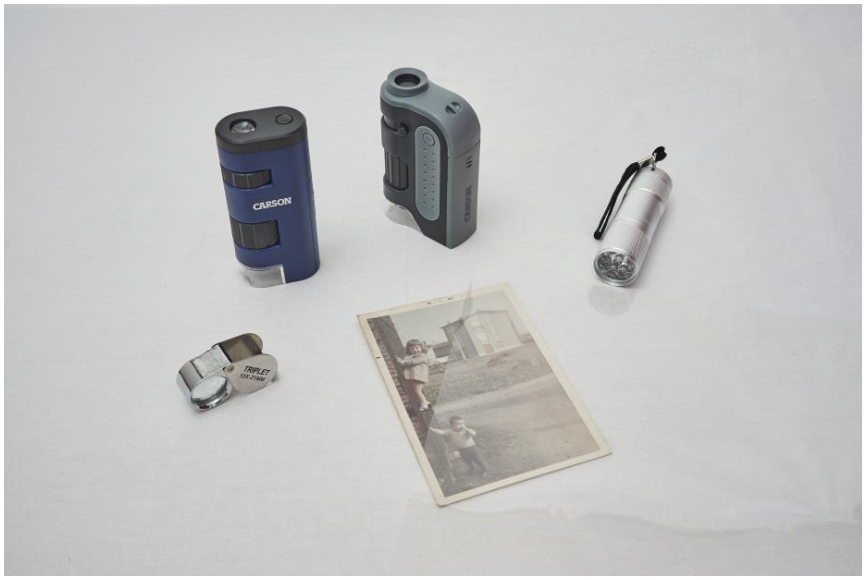
3.1. Instruments
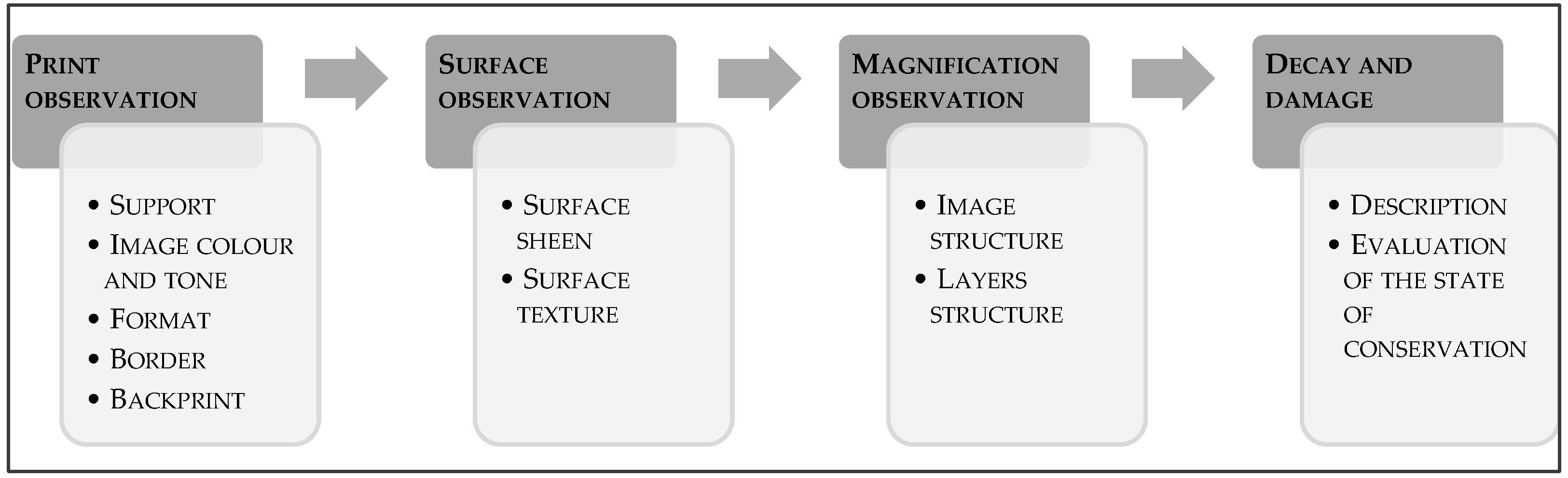
3.2. The Methodology
- print observation: a naked eye examination of the front and back print of the photograph to have a preliminary idea of the type of support, colours, and tones of the image, the formats, the border, and the back print.
- surface observation: a visual examination of the print through grazing light to define the sheen and texture of the surface.
- magnification observation: a visual examination through the portable optical instruments introduced above to define the structure and layers of the image.
- decay and damage observation: a visual analysis of the alteration and degradation of the print to evaluate its state of conservation.
3.2.1. Print Observation
3.2.2. Surface Observation
3.2.3. Magnification Observation
3.2.4. Decay and Damage Observation
4. Protocol Application Examples
5. The Open-Source Website
6. Conclusions
Author Contributions
Funding
Data Availability Statement
Acknowledgments
Conflicts of Interest
References
- Gwain, W. Photo Conservation-Photographic Process Controlled Vocabulary. Gawain Weaver Art Conservation. 2014. Available online: https://gawainweaver.com/library/ (accessed on 20 November 2022).
- Paul, M. An Introduction to Color Photographs: Technology, Terminology and Identification. Paul Messier Conservation of Photographs & works on paper. 1999. Available online: https://www.paulmessier.com/resources (accessed on 25 November 2022).
- Bertrand, L. A Guide to the Preventive Conservation of Photograph Collections. Los Angeles: Getty Conservation Institute. 2003. Available online: https://www.getty.edu/conservation/publications_resources/books/preven_conserv_photo.html (accessed on 10 November 2022).
- Henry, W.; Brower, C. The Permanence and Care of Color Photographs: Traditional and Digital Color Prints, Color Negatives, Slides, and Motion Pictures; Digital Editions; Preservation Publishing Company: Grinnell, IA, USA, 2003; Available online: http://www.wilhelm-research.com/pdf/HW_Book_01_of_20_HiRes_v1c.pdf (accessed on 15 November 2022).
- National Film Preservation Foundation. The Film Preservation Guide: The Basics for Archives, Libraries, and Museums, National Film Preservation Foundation; National Film Preservation Foundation: San Francisco, CA, USA, 2004; Available online: https://www.filmpreservation.org/preservation-basics/the-film-preservation-guide-download (accessed on 15 November 2022).
- Robert, H.; Erf, G. Exploring Color Photography: From Film to Pixels, 6th ed.; Focal Press–Taylor and Francis Group: New York, NY, USA, 2015. [Google Scholar]
- Atelier de Restauration et de Conservation des Photographies de La Ville de Paris. Lingua Franca: A Common Language for Conservators of Photographic Materials; Library and Archives Canada: Ottawa, ON, Canada, 2018; Available online: http://data2.archives.ca/e/e448/e011188307.pdf (accessed on 9 November 2022).
- Image Permanence Institute. Graphic Atlas–Identification–Cromogenic Process. Rochester Institute of Technology. 2021. Available online: http://www.graphicsatlas.org/identification/?process_id=88#overview (accessed on 10 November 2022).
- Gwain, W.; Long, Z. Chromogenic Characterization: A Study of Kodak Color Prints, 1942–2008. Available online: https://www.academia.edu/4705628/A_STUDY_OF_KODAK_COLOR_PRINTS_1942_2008 (accessed on 9 November 2022).
- Michael, R.P. Focal Encyclopedia of Photography–Digital Imaging, Theory and Applications, History and Science; Digital edition; Elsevier: Oxford, UK, 2007. [Google Scholar]
- Image Permanence Institute. Graphic Atlas–Identification–Silver Dye Bleach; Rochester Institute of Technology: Rochester, NY, USA, 2021; Available online: http://www.graphicsatlas.org/identification/?process_id=326 (accessed on 10 November 2022).
- Hunt, R.W.G. The Reproduction of Colour, 6th ed.; John Wiley & Sons Ltd.: Chichester, UK, 2004. [Google Scholar]
- Image Permanence Institute. Graphic Atlas–Identification–Dye Diffusion Transfer; Rochester Institute of Technology: Rochester, NY, USA, 2021; Available online: http://www.graphicsatlas.org/identification/?process_id=111#overview (accessed on 10 November 2022).
- Lindblom, K.L. Edwin Land and Instant Photography; American Chemical Society: Washington, DC, USA, 2015; Available online: https://www.acs.org/content/dam/acsorg/education/whatischemistry/landmarks/landinstantphotography/edwin-land-polaroid-booklet.pdf (accessed on 20 November 2022).
- Image Permanence Institute. Graphic Atlas-Identification-Internal Dye Diffusion Transfer; Rochester Institute of Technology: Rochester, NY, USA, 2021; Available online: http://www.graphicsatlas.org/identification/?process_id=333 (accessed on 10 November 2022).
- Image Permanence Institute. Graphics Atlas-Welcome; Rochester Institute of Technology: Rochester, NY, USA, 2017; Available online: http://www.graphicsatlas.org/ (accessed on 10 November 2022).
- Gwain, W. Photo Conservation-Photographic Processes; Gawain Weaver Art Conservation: Lagunitas, CA, USA, 2020; Available online: https://gawainweaver.com/processID (accessed on 20 November 2022).


| Products | |
|---|---|
| Kodak [9] | Type C, Kodak Ektacolor Paper, Kodacolor, Kodak Royal, Endura N, Y and E surfaces, Supra Endura |
| Fuji [8] | Fujicolor |
| Agfa [8] | Agfacolor Neu, Agfacolor Paper |
| Products | |
|---|---|
| Ilford [11] | Cibachrome (CCP), Cibachrome A (CCP-A), Photo-Me, Cibachrome Copy (CCO), Cibachrome-II, Cibachrome II-A (CCP-A II), Cibachrome CF DeLuxe (CF), Ilford Color print, Ilfochrome Classic |
| Agfa [11] | Gasparcolor |
| Ansco [11] | Gasparcolor Opaque |
| Products | |
|---|---|
| Polaroid [13] | Polacolor, Polacolor 1, Polacolor 2, Polacolor ER, Polacolor Pro, Polacolor Pro 100, Type 690, VIVA Colour, Type 48, Type 38, Type 108, Type 88 |
| Kodak [13] | Ektaflex PCT |
| Fuji [13] | Fuji FP-800, Fuji FP-100 |
| Agfa [13] | Agfachrome Copycolor |
| Products | |
|---|---|
| Polaroid [15] | 600 Film, Captiva Film, iZone Film, Mio Film, Pocket Film, Spectra Film, SX-70 Land Film, Time Zero Film |
| Kodak [15] | HS-144-10, Kodamatic, PR-10, Trimprint |
| Fujifilm [15] | FI-800GT, Instax Film, Pivi Film, Insax Mini, Instax Wide, Fuji integral film (FI–160) |
| Agfa [15] | Agfachrome speed |
| Process | Support |
|---|---|
| Dye coupler print [2,8,9] | Pigmented cellulose triacetate, fiber-based (1942–1968), resin coated (1968-present), polyester or laminate support |
| Dye destruction print [2,11] | 1967: cellulose triacetate. 1979–2005: resin-coated support 1980–2012: polyester. |
| Dye diffusion transfer [2,13] | Polyester or paper supports. |
| Internal dye diffusion transfer print [2,15] | Polaroid, Fujifilm: film enclosed between black polyester support and transparent polyester support by a paper border covered with a white film. The bottom edge hides the reagent capsule and is wider than the side and top edges. |
| Process | Image Colour and Tone |
|---|---|
| Dye coupler print [2,8,9] | Shift in colour balance and/or fading. Highlights and borders may appear yellow. From the mid-80s, good dye stability with little to no shift in colour or fading. |
| Dye destruction print [2,11] | Good dye stability, high saturation, clear image. |
| Dye diffusion transfer print [2,13] | Polacor: fading of yellow and magenta dyes. After 1975: uniform and saturated colour. The nature of the process can cause imperfections: white lines, equidistant white spots, small white spots, white areas and brown stains. |
| Internal dye diffusion transfer print [2,15] | Uniform and saturated colour. The nature of the process can cause imperfections: uniform white or coloured spots, white areas. |
| Process | Format |
|---|---|
| Dye coupler print [2,8,9] | European formats (cm): 9 × 13, 10 × 15, 13 × 18, 18 × 24, 20 × 30, 30 × 45 American formats (in): 3½ × 3, 3½ × 5, 4 × 6, 5 × 7, 8 × 10, 11 × 14, 16 × 20, 20 × 24, 20 × 30, 24 × 30 |
| Dye destruction print [2,11] | European formats (cm): 9 × 13, 10 × 15, 13 × 18, 18 × 24, 20 × 30, 30 × 45 American formats (in): 3½ × 3, 3½ × 5, 4 × 6, 5 × 7, 8 × 10, 11 × 14, 16 × 20, 20 × 24, 20 × 30, 24 × 30 |
| Dye diffusion transfer print [2,13] | Roll film: Type 48 (3¼ × 4 ¼ in), Type 38 (2½ × 3¼ in). Pack: Type 108 (3¼ × 4¼ in), Type 88 (3¼ × 4¼ in), generally 4 × 5 in and 8 × 10 in formats. |
| Internal dye diffusion transfer print [2,15] | Polaroid: t.a. 3½ × 4¼ in; i.a. 3 1/8 × 3 1/8 in Spectra Film (1986–2006): t.a. 4 × 4 1/16 in; i.a. 2 7/8 × 3 5/8 in Captiva Film (1993–2006): t.a. 2½ × 4 3/8 in; i.a. 2 1/8 × 2 7/8 in Pocket Film: t.a. 6 5/8 × 1 3/8 in; i.a. 1 3/8 × 1 7/8 in AutoFilm Type 339: t.a. 4¼ × 4½ in; i.a. 3 × 4 in Kodak Film: t.a. 3¾ × 4 in; i.a. 2 5/8 × 3 5/8 in Fujifilm (1980): t.a. 9,7 × 10,2 cm; i.a. 6,8 × 9,1 cm Instax Mini (1998): t.a. 5,4 × 8,6 cm; i.a. 4,6 × 6,2 cm Instax Wide: t.a. 8,6 × 10,8 cm; i.a. 6,2 × 9,9 cm Fuji integral film (FI-160): t.a. 4 × 5 in; i.a. 3 1/8 × 3 1/8 in |
| Process | Border |
|---|---|
| Dye coupler print [2,8,9] | Before the 70s, white. After the 70s absence of the border. |
| Dye destruction print [2,11] | Generally absent or black. Ilford prints (1953–1963): white border. |
| Dye diffusion transfer print [2,13] | White border, generally characterized by adhesive residues. |
| Internal dye diffusion transfer print [2,15] | White border. |
| Process | Backprint |
|---|---|
| Dye coupler print [2,8,9] | 1942–1960: stamps with the date of processing. 1958: backprint showing the factory. 1960–1970: optical print on the border. From the type of words reported it is possible to make a dating:
|
| Dye destruction print [2,11] | Backprints only on resin-coated supports. |
| Dye diffusion transfer [2,13] | Along one of the edges: print with production code and brand name. Occasionally the film type and exposure number were printed in the corners.
|
| Internal dye diffusion transfer print [2,15] | Generally, backprint with the factory name. Polaroid: production code (month, year and development camera). Kodak Trimprint film: black and matte back. |
| Process | Surface Sheen |
|---|---|
| Dye coupler print [2,8,9] | Fibre-based supports: glossy Acetate and polyester supports: high-gloss Kodachrome prints: defferential gloss Resin coated papers: matte Resin coated papers with texture: semi-matte, semi-glossy or glossy. |
| Dye destruction print [2,11] | Acetate and polyester supports: high-gloss (+lacquer: glossy, semi-glossy or matte; + plastic laminate: glossy or matte) Resin coated papers: glossy or semi-gloss |
| Dye diffusion transfer [2,13] | Glossy with adhesive residues, surface undulations, scratches, debris and uneven coating. |
| Internal dye diffusion transfer print [2,15] | Polaroid: glossy or high-gloss surface Kodak Film: semi-glossy surface with applied texture (Satinluxe) |
| Process | Surface Texture |
|---|---|
| Dye coupler print [2,8,9] | Fiber-based supports: smooth surface Resin coated paper: smooth surface of semi-gloss surface (Kodak Y and Kodak N texture) Acetate and polyester supports: smooth surface |
| Dye destruction print [2,11] | Acetate and polyester supports: smooth surface, changeable by coating Resin coated papers: lightly rough surface |
| Dye diffusion transfer [2,13] | Smooth surface with uniform undulations. |
| Internal dye diffusion transfer print [2,15] | Smooth surface. Kodak Fim: slightly textured (Satinluxe) |
| Process | Image Structure | |
|---|---|---|
| At Low Magnification (10x) | At High Magnification | |
| Dye coupler print [2,8,9] | Continuous tones | Dye clouds |
| Dye destruction print [2,11] | Dye clouds | White halos |
| Dye diffusion transfer print [2,13] | Continuous tones | Continuous tones |
| Internal dye diffusion transfer print [2,15] | Continuous tones | Continuous tones |
| Process | Decay and Damage |
|---|---|
| Dye coupler print [2,3,4,8,9] | Dyes are unstable by nature, and fading occurs whether the print is exposed to light or stored in the dark. Cyan dyes tend to fade in the dark, so the photograph appears too red (thermal fading); magenta dyes, on the other hand, tend to fade causing a blue or green tint (light fading). Unreacted residual couplers are also unstable, especially magenta ones that cause yellowish discolouration of highlights and edges. Fibre-based papers produced before the 60s and resin-coated papers produced in the 70s can show:
|
| Dye destruction print [2,3,4,11] | Azo dyes are more stable than chromogenic dyes and fade at the same rate. This phenomenon causes an overall loss of density. Until the 80s, the most used support was in cellulose triacetate. This material can undergo chemical deterioration: vinegar syndrome and yellowing. An improper handling or incorrect storage can cause: abrasions, dents, traces and loss of binder along the edges. A prolonged exposure to an aqueous environment can cause dyes migration and delamination. |
| Dye diffusion transfer [2,3,4,13] | Polacolor: yellow and magenta dyes fading Polacolor 2: different rate of fading Polacolor ER: uniform fading Kodak Ektaflex print: magenta toning Agfachrome Speed print: poor light stability The common forms of alteration and degradation are:
|
| Internal dye diffusion transfer print [2,3,4,15] | Generally, Polaroids stored in conditions of darkness can be characterized by a yellowing, caused by dye migration in highlight areas. SX-70 materials show dyes fading and microcracking, caused by relative humidity fluctuation. Occasionally, Kodak Prints will show yellow spots on white borders caused by exposure to heat and light during the drying process. Fujifilm materials are less inclined to fade than Polaroid and Kodak materials. The coating layer is susceptible to scratches, abrasions and fingerprints. Some prints can show pigment aggregations, with a characteristic snowflake form. |
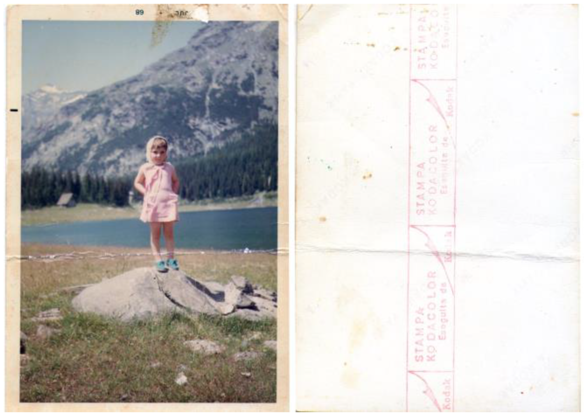
| Photograph | Figure 3 | |
| Code | MR01 | |
| Date | 1968 | |
| Print observation | Support | Resin-coated paper |
| Colour and tone | Shift in colour balance and fading. Highlights and borders appear yellow. | |
| Format | 9 × 13 cm | |
| Border | White with an optical print of the date | |
| Backprint | “A Kodak Paper” Magenta stamp: “Stampa Kodacolor eseguita da Kodak” | |
| Surface observation | Surface sheen | glossy |
| Surface texture | smooth surface | |
| Magnifications observation | Image structure | Low magnification (10x): continuous tones High magnification: dye clouds |
| Layers structure | Multilayer support consisting of paper, inserted between two layers of polyethylene, and layers of emulsion. | |
| Decay and damage | Description | Support and surface in poor condition. Presence of cracks, gaps, abrasions, and signs of handling. Presence of a crease parallel to the short side. Gluey foreign deposit near the upper edge. Slight fading of tones. |
| Judgment | 2 | |
| Process | Dye coupler print | |
| Photograph | Figure 4 | |
| Code | CT08 | |
| Date | 80s–90s | |
| Print observation | Support | Polyester |
| Colour and tone | Good dye stability, high saturation, clear image. | |
| Format | 20 × 35 cm | |
| Border | - | |
| Backprint | “A Kodak Paper” “Ilford Cibachrome” print. At the corners, residues of the adhesive used to glue the print to a secondary cardboard support. | |
| Surface observation | Surface sheen | matte |
| Surface texture | rough surface | |
| Magnifications observation | Image structure | Low magnification (10x): continuous tones High magnification: white halos |
| Layers structure | Prints consisting of three layers of silver gelatin emulsion containing the dyes, superimposed on paper support coated with plastic or resin. | |
| Decay and damage | Description | Support in good condition. There are some signs of handling. |
| Judgment | 5 | |
| Process | Dye destruction print | |
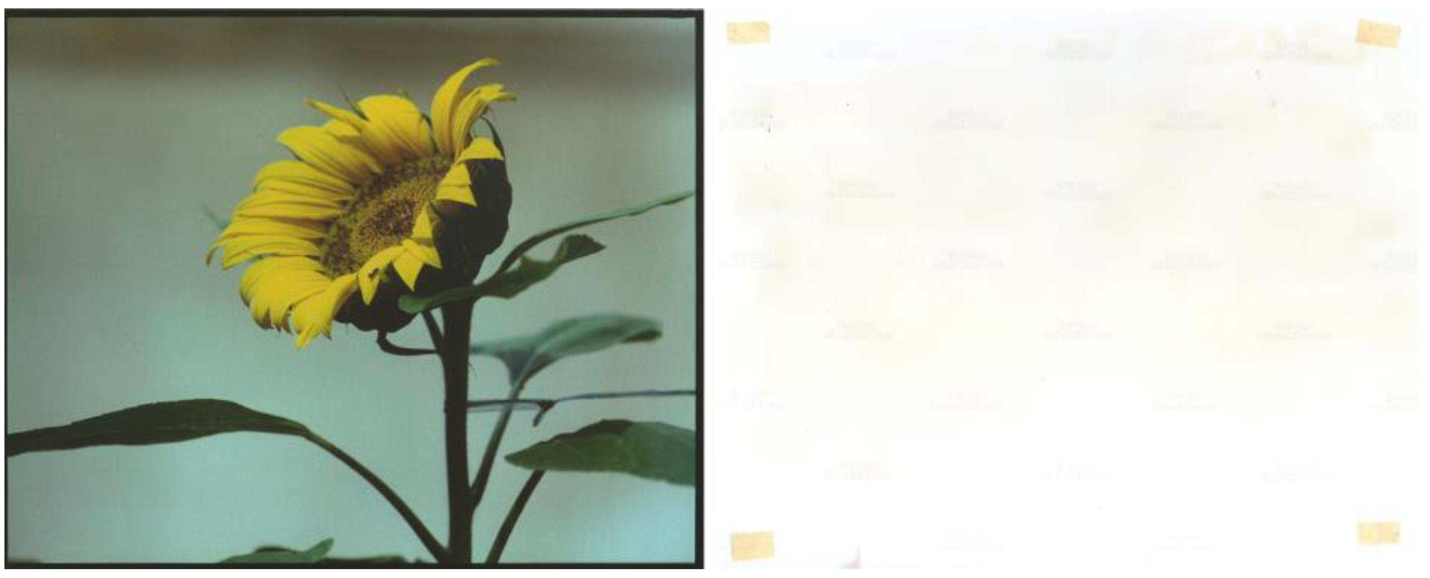
| Photograph | Figure 5 | |
| Code | AC07 | |
| Date | 1977 | |
| Print observation | Support | Polyester |
| Colour and tone | Uniform colour. | |
| Format | 3 1/8 x 3 1/8 in | |
| Border | White | |
| Backprint | “Polacolor” print; “B74301PG” stamp. | |
| Surface observation | Surface sheen | glossy |
| Surface texture | smooth surface | |
| Magnifications observation | Image structure | Low magnification (10x): continuous tones High magnification: continuous tones |
| Layers structure | The supports consist of a positive receiving sheet, an acid polymeric layer, a barrier layer, a paper base (with barite), and a polyethylene back coating. | |
| Decay and damage | Description | Print in fair condition: the surface is characterised by scratches and fingerprints, the support is interested by some signs of handling. There are yellowish stains on the left edge. Slight fading of tones. |
| Judgment | 3 | |
| Process | Instant photography: Dye diffusion transfer print | |
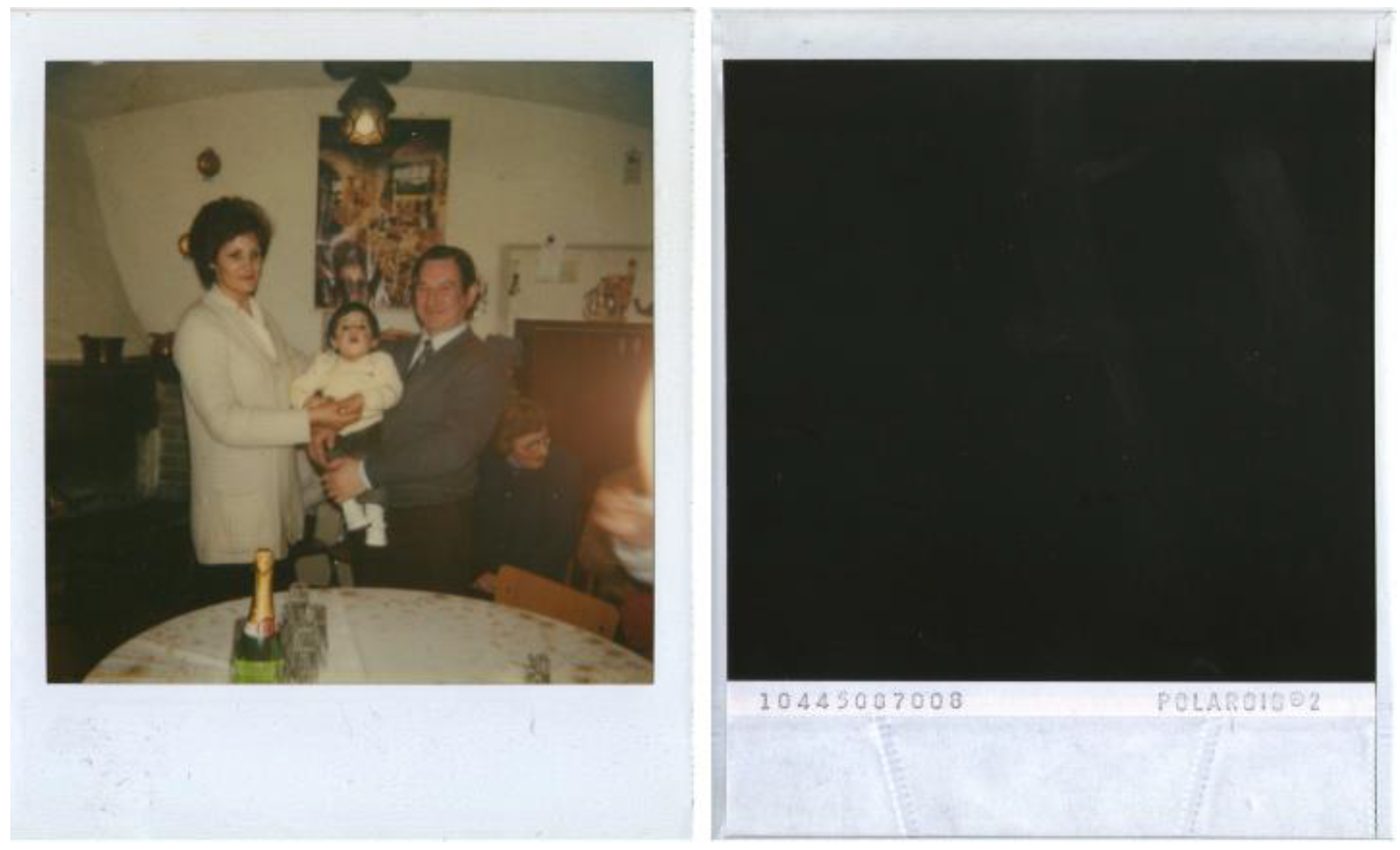
| Photograph | Figure 6 | |
| Code | MP06 | |
| Date | Late 80s | |
| Print observation | Support | Polyester |
| Colour and tone | Uniform and saturated colour. | |
| Format | 9 × 11 cm | |
| Border | White | |
| Backprint | “Polaroid 2” print; “09943066043” stamp | |
| Surface observation | Surface sheen | glossy |
| Surface texture | smooth surface | |
| Magnifications observation | Image structure | Low magnification (10x): continuous tonesHigh magnification: continuous tones. |
| Layers structure | There are: a transparent polyester top layer, an image receiving layer (polymeric mordant), a white titanium dioxide/matting layer, three thin layers of silver emulsion, and a black polyester support. | |
| Decay and damage | Description | Support and surface in good conditions. There are some scratches and fingerprint on the back print. Slight fading of tones. |
| Judgment | 4 | |
| Process | Instant photography: Internal dye diffusion transfer print | |
Publisher’s Note: MDPI stays neutral with regard to jurisdictional claims in published maps and institutional affiliations. |
© 2022 by the authors. Licensee MDPI, Basel, Switzerland. This article is an open access article distributed under the terms and conditions of the Creative Commons Attribution (CC BY) license (https://creativecommons.org/licenses/by/4.0/).
Share and Cite
Cattaneo, A.; Sarti, B.; Plutino, A.; Rizzi, A. On the Identification of Colour Photographic Processes. Heritage 2022, 5, 4074-4088. https://doi.org/10.3390/heritage5040210
Cattaneo A, Sarti B, Plutino A, Rizzi A. On the Identification of Colour Photographic Processes. Heritage. 2022; 5(4):4074-4088. https://doi.org/10.3390/heritage5040210
Chicago/Turabian StyleCattaneo, Ambra, Beatrice Sarti, Alice Plutino, and Alessandro Rizzi. 2022. "On the Identification of Colour Photographic Processes" Heritage 5, no. 4: 4074-4088. https://doi.org/10.3390/heritage5040210
APA StyleCattaneo, A., Sarti, B., Plutino, A., & Rizzi, A. (2022). On the Identification of Colour Photographic Processes. Heritage, 5(4), 4074-4088. https://doi.org/10.3390/heritage5040210