Article

Recycling of Sustainable Automotive Structural Composites via Pyrolysis, Technical and Climate Impact Evaluation


1
Division of Bioeconomy and Health, Biorefinery and Energy, Sustainable Resource Conversion, Research Institute of Sweden AB, Box 726, SE-941 28 Piteå, Sweden
2
Independent Researcher, SE-944 31 Piteå, Sweden
3
Division of Materials and Production, Sustainable Material Systems, Environment and Sustainable Chemistry, Research Institute of Sweden AB, Box 5604, SE-114 86 Stockholm, Sweden
4
Division of Materials and Production, Sustainable Material Systems, Composite Technology, Research Institute of Sweden AB, Box 271, SE-941 26 Piteå, Sweden
5
Division of Materials and Production, Sustainable Material Systems, Composite Technology, Research Institute of Sweden AB, Box 104, SE-431 22 Mölndal, Sweden
*
Author to whom correspondence should be addressed.
Clean Technol. 2026, 8(2), 59; https://doi.org/10.3390/cleantechnol8020059
Submission received: 19 February 2026 / Revised: 27 March 2026 / Accepted: 3 April 2026 / Published: 17 April 2026
(This article belongs to the Special Issue Selected Papers from Circular Materials Conference 2025)

Highlights

What are the main findings?
  • Pyrolysis performance and the recycling potential of composites are strongly material-dependent: glass fibre composites enable fibre recovery for reuse, while natural fibre composites yield bio-oil for biofuel applications.
  • Recovered polymers have differentiated value chains, ranging from monomer recovery (PA6) to hydrocarbon or aromatic fractions that can substitute fossil-based naphtha or petrochemical feedstocks (PP, polyester).
What are the implications of the main findings?
  • Designing composite materials and recycling routes in tandem is critical, as tailoring material formulations to pyrolysis outcomes can maximise both technical recovery and environmental benefits.
  • Achieving meaningful climate gains from composite recycling requires efficient, low-impact recycling processes and high substitution credits, underlining the importance of optimized recycling pathways within a circular, low-carbon materials system.

Abstract
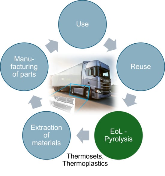
Sustainable structural composites can significantly lower vehicle-related emissions. To evaluate the recycling of different composite materials, laboratory-scale pyrolysis was conducted and assessed both technically and environmentally. Two demonstrators were studied: a truck side skirt made from natural flax and hemp fibres with polypropylene (PP), and a car front header composed of glass fibres and PP. Additional materials examined included thermoplastic composites containing polyamide 6 (PA6), bio-based polyamide 11 (PA11) and thermoset polyester. Results showed that material type strongly influenced the pyrolysis outcome, product composition and recycling potential. Glass fibres could be recovered and reused as reinforced fibres, while natural fibres could be recovered as biooil for potential use in biofuel production. Polymers were recovered as pyrolysis products that, depending on their composition, can be used in different applications, from recovering monomers from PA6 to producing hydrocarbons that may replace naphtha (from PP) or aromatics (from polyester) in the petrochemical industry. Life cycle assessment (LCA) findings revealed that the climate impact of composite recycling is primarily driven by the environmental burdens of the recycling process itself and by the ability of recovered materials and chemicals to substitute conventional fossil-based alternatives. Efficient recycling pathways are therefore essential to maximising environmental benefits.

Graphical Abstract

1. Introduction

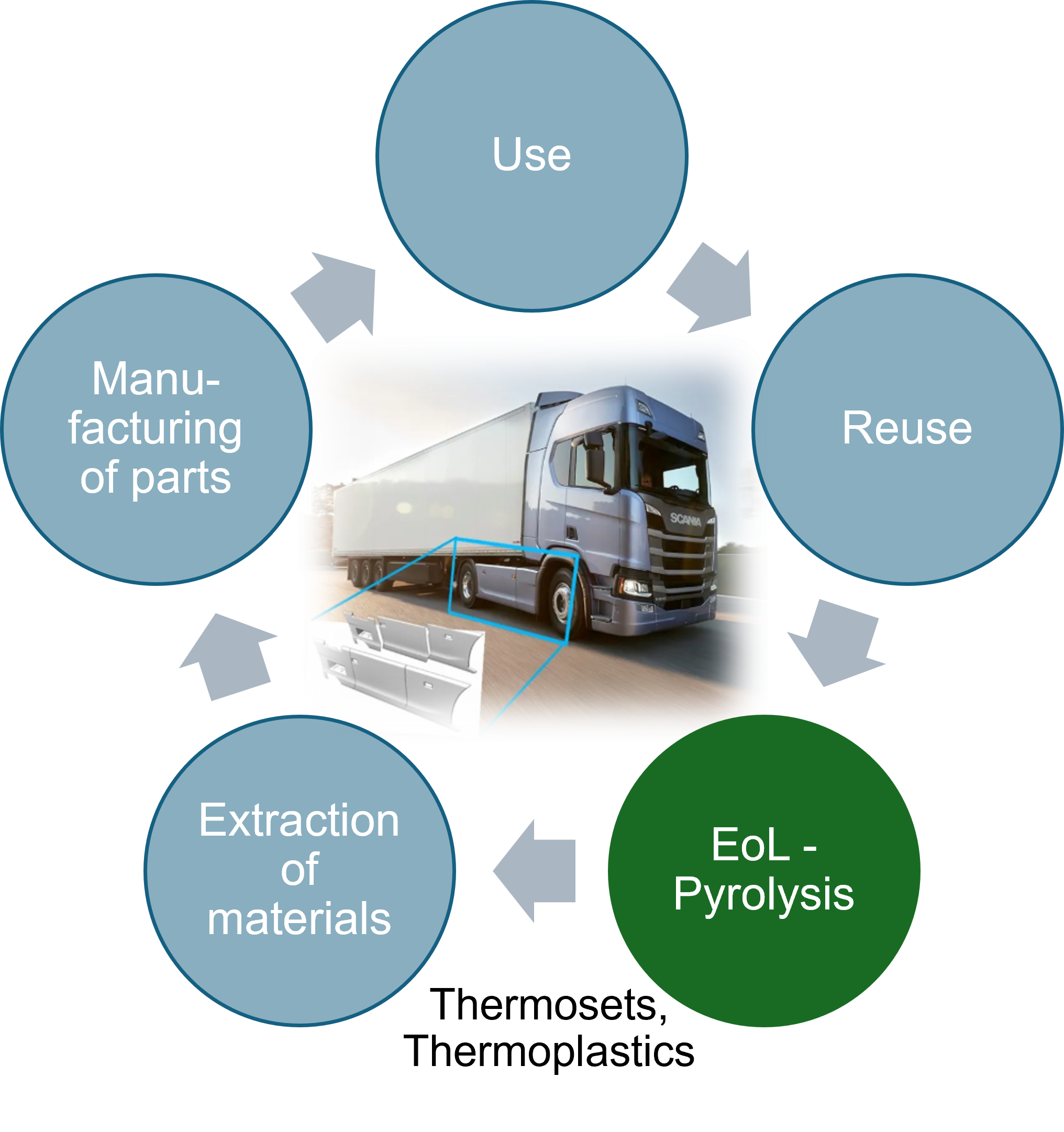
The transport sector is one of the largest sources of CO2 emissions in the European Union [1]. Electrification of the transport fleet, utilising green electricity for charging and lightweight structural fibre-reinforced polymers (FRPs) are considered the main pathways to reduce emissions from the use phase of vehicles [2,3]. However, to decrease the environmental impact throughout the whole life cycle of the vehicles, it is necessary to consider impacts from the extraction and processing of materials, manufacturing and assembly of parts, use, reuse and end-of-life (EoL) recycling [4].
Currently, the most common approaches for end-of-life FRP materials are landfill and incineration [5], mainly due to the material complexity. FRPs are composite materials consisting of strong fibres, usually glass or carbon fibres, embedded in a resin matrix, which consists of thermoset or thermoplastic polymers. These materials are usually designed for optimising their mechanical properties and not with regard to recycling.
Different recycling routes for EoL composite materials have been suggested in the literature, i.e., energy, mechanical, chemical and thermochemical recycling [6]. Pyrolysis, which is a thermochemical recycling technology where the organic material is decomposed in an inert atmosphere, is a promising technology that has the potential to recover both high-quality fibres and polymers separately. The secondary pyrolysis products can further be recycled into new chemicals and materials, contributing to a circular economy and reduced environmental impact [6]. However, pyrolysis is an energy-intensive process, and the net environmental benefit depends on the balance between processing emissions and the quality and yield of recovered secondary materials.
Utilising sustainable bio-based components as input material in composites can affect the climate impact positively. Bio-composites are usually lighter than conventional glass fibre-reinforced plastics, but they can exhibit poor moisture resistance and lower mechanical performance [7]. Therefore, in-depth investigations to increase the use of bio-composites in more structural components are necessary.
Life cycle assessment (LCA) serves as the principal methodology for quantifying environmental impacts throughout a product’s life cycle, enabling a holistic evaluation of extraction, production, use, and recycling processes. International standards such as ISO 14040 [8] and ISO 14044 [9] prescribe LCA’s four iterative phases (described in the next section), providing a systematic framework that helps avoid sub-optimisation across product systems. Since the recycling of composite materials is challenging, this underscores the need for process-specific LCAs that evaluate emerging recycling strategies.
In the current research project [10], within which the present research was performed, the whole value chain for sustainable and structural composites within the automotive industry was evaluated based on its readiness level and climate impact. Two composite demonstrators were designed, manufactured and evaluated: a truck side skirt and a car front header. For the truck side skirt, climate impact assessments were performed with both a novel composite material composed of natural fibre and polypropylene (PP) and with conventional material, including plastics and steel. The results showed that replacing the conventional material with the new composite could substantially reduce climate impact, achieving a 78% reduction across the entire life cycle [4].
Different types of materials for the demonstrators were evaluated and selected based on their sustainability, availability and thermomechanical properties. The materials evaluated from a recycling perspective were composite samples including thermoplastics polyamide 6 (PA6), polypropylene, bio-based polyamide 11 (PA11) or thermoset polyester and fibres composed of glass or natural fibres from flax and hemp. The recycling of different types of composite materials was evaluated experimentally via pyrolysis at laboratory scale. Based on the technical evaluation, a comparison of the climate impact perspectives of a selection of materials was also conducted. The present study applies ISO-compliant LCA to experimentally performed pyrolysis of three automotive composite components: a natural-fibre/polypropylene (NF/PP) side skirt, a natural-fibre/polyamide-11 (NF/PA11) side skirt, and a sheet moulding compound (SMC) header. Climate impact was evaluated using the software SimaPro (version 10.3.0.1.), integrating primary process data from the laboratory-scale pyrolysis. Special attention is given to the substitution potential of recovered materials, including condensed liquids and solids, as well as glass fibres, which may replace virgin materials such as petrol, naphtha, hydrocarbons and conventional glass fibres.

2. Materials and Methods

Five different composite materials were characterised and pyrolysed at laboratory scale. Based on the data generated from the laboratory pyrolysis experiments, a climate impact analysis was conducted on three selected materials.

2.1. Materials

The selection of materials for the composites was based on their sustainability, availability and thermomechanical properties. The requirements of the two types of components, side skirts (truck) and header (car), were set by the original equipment manufacturers (OEM) participating in the project. Several material combinations were evaluated against these requirements, as well as more practical requirements such as project time frame and budget. The main requirements for the car component focused on stiffness, energy absorption in the event of a crash, weight saving compared to the current solution, and cost. Initially, the components were required to withstand the lacquering process at high temperatures; this requirement was then relaxed, allowing for thermoplastic composites. For the truck component, the main requirements were sufficient stiffness to avoid wind-induced vibrations, weight savings compared to the current solution, cost, the ability to withstand the cleaning and lacquering process—which was less severe than for the car component—as well as a class A surface finish. The selection resulted in a combination of flax and hemp fibres (natural fibres, NF) with PP for the truck side-skirt demonstrator and glass fibres (GF) with PP for the car front header demonstrator. From a recycling perspective, some additional material samples in addition to the combinations used in the final demonstrators were examined. This resulted in the experimental evaluation of composite samples with the thermoplastics PA6, PP and the bio-based PA11, thermoset polyester, glass fibres, as well as natural fibres from flax and hemp. The compositions of the composites are described in Table 1. As indicated in the table, composite no. 1 was selected to represent the truck component, while composite no. 5 was selected to represent the car component. The life cycle analysis was conducted on composite nos. 1, 2 and 3.

Material Characterisation

The composite materials were initially analysed thermogravimetrically to determine the decomposition temperature of the different organic components. In the thermogravimetric analysis (TGA), the mass change of the samples is measured as a function of time and temperature while subjected to a controlled temperature program in an inert atmosphere. The TGA was conducted using a Perkin Elmer Pyris 1 TGA (PerkinElmer Inc., Waltham, MA, USA). The experiments were performed in an inert atmosphere at a flow of nitrogen of 20 mL/min. The weight of the sample was approximately 3 mg for all experiments. The sample was equilibrated at room temperature, 25 °C, before being heated to 700 °C at a heating rate of 10 °C/min.
The materials were further analysed using analytical pyrolysis to give an indication of the pyrolysis properties of the different composite materials. The measurements were carried out using a multi-shot pyrolyser (Frontier Laboratories Ltd., Koriyama, Fukushima, Japan) coupled to a Shimadzu GCMS-QP2010 Ultra system (Shimadzu, Kyoto, Japan), consisting of a gas chromatograph (GC), a quadrupole mass spectrometer (MS), and a flame ionisation detector (FID)—a Py-GC/MS-FID setup. A capillary column Restek RTX-1701 (Restek Corporation, Bellefonte, PA, USA) (60 m × 0.25 mm, id 0.25 µm film thickness) was employed and connected to both detectors using a Y-splitter (Restek Corporation, Bellefonte, PA, USA) together with restriction columns: 10,100 (0.5 m × 0.1 mm) (Restek Corporation, Bellefonte, PA, USA) leading to the MS and 10,043 (0.5 m × 0.25 mm) (Restek Corporation, Bellefonte, PA, USA) directed to the FID.
Prior to the analysis, a powder of the samples was produced to facilitate the small sample size of approximately 0.3 mg.

2.2. Laboratory-Scale Pyrolysis Experiments

Laboratory-scale pyrolysis experiments were carried out using a batch reactor setup previously outlined in Johansson et al., 2024 [11]. Briefly, the system comprises a batch pyrolysis reactor, a system for collecting condensable products, and instruments for analysing the non-condensable gas. The composite material was loaded into the batch pyrolysis reactor, where it was thermally decomposed under an inert gas atmosphere, producing pyrolysis vapours, a solid residue, and non-condensable gas. Within the condensation unit, the pyrolysis vapours were cooled and transformed into liquid or solid products, which were captured in two separate collection vessels. The remaining non-condensable gases were subsequently examined to determine their composition.
In each run, approximately 400 g of the material was introduced into the reactor. Heating was applied at a rate of 5 °C/min until the internal gas temperature reached 500 °C (for sample nos. 1, 3 and 5) and 350 °C, followed by 500 °C (for sample no. 2). To maintain an oxygen-free environment and ensure efficient heat transfer, a pre-heated flow of nitrogen at 3 NL/min was continuously supplied to the reactor. The residence time of the hot pyrolysis vapours fluctuated throughout the process as the decomposition rate changed, but the average duration was roughly six minutes. It is possible to optimise the pyrolysis conditions, i.e., adapt the temperature, vapour residence time and addition of catalysts, to enhance the product distribution and quality, although such optimisation was outside the scope of this project. Throughout the experiments, the non-condensable gas stream was continuously monitored for CO, CO2, H2, N2, O2, and CH4 using a Varian 490 micro gas chromatograph (Varian, Inc., Walnut Creek, CA, USA) equipped with two thermal conductivity detectors (TCD). Larger organic compounds in the gas were also sampled in gas bags and later analysed with a stationary GC fitted with a flame ionisation detector (GC-FID, Varian CP-3800, Varian, Inc., Walnut Creek, CA, USA). The pyrolysis run was considered complete once the online GC indicated that no further pyrolysis gases were being produced, which generally occurred after about 120 min at 500 °C. After this point, the furnace was switched off and allowed to cool to ambient temperature under a reduced nitrogen flow (0.5 L/min). Once cooled, the system was disassembled and all products were collected. If phase separation occurred in the condensed products, the individual phases were isolated and weighed separately. By recording the mass of all components and materials before and after each experiment, and by quantifying the gas-phase products, mass balances were established and product yields were calculated.
If phase separation occurred in the condensed products, the individual phases were isolated and weighed separately. By recording the mass of all components and materials before and after each experiment, and by quantifying the gas-phase products, mass balances were established and product yields were calculated.

2.2.1. Analysis of Pyrolysis Products

The organic fraction in the condensed products was evaluated semi-quantitatively using GC/MS-FID. The GC/MS-FID measurements were carried out on the same gas chromatograph used for the analytical pyrolysis, a Shimadzu GCMS-QP2010 Ultra (Shimadzu, Kyoto, Japan) equipped with a quadruple mass spectrometer (MS) and a flame ionisation detector (FID). Prior to the analysis, the organic condensed samples were diluted in toluene at a 1:10 ratio, whereas the aqueous samples were examined without any dilution. Compound identification was performed with the mass spectrometer, and their semi-quantitative levels were determined using the FID. In the Results section, the detected compounds are categorised into different chemical groups.
The liquid and solid pyrolysis products were analysed with regard to elemental composition and heating value at an external laboratory.

2.2.2. Calculation of Energy Requirements

The energy requirement for the pyrolysis of the different composites was estimated by energy measurements on a small laboratory reactor system. However, small-scale reactors are typically less energy-efficient than larger reactors; therefore, the following method was used to determine the required energy.
To estimate the heat of pyrolysis, the furnace power output was measured as a function of the furnace temperature and time. With this data, together with the ambient temperature, the heat losses could be estimated at the end of the experiment, when the pyrolysis was finalised, and when the system reached steady state. With this estimated heat loss and the known temperature difference between the furnace and the ambience, a temperature-dependent heat loss constant could be calculated. The heat for the experiment represents the difference between the measured furnace power output and the temperature-dependent heat loss, as well as the sum of each measured data point. By removing the energy for heating the steel reactor, the furnace itself and the nitrogen added to the reactor, the energy of pyrolysis could be estimated.

2.3. LCA Methodology

Life cycle assessment (LCA) is a standardised approach used to evaluate the environmental impacts connected to all stages of a product life cycle. In LCA, emissions and resources resulting from or consumed by the product at hand are traced using one of the following approaches:
  • “cradle to gate”, where the environmental impact of a product is evaluated from the extraction of raw material until it exits the manufacturing “gate”;
  • “cradle to grave”, assessing the environmental impact of a product across its entire lifespan, from raw material extraction, manufacturing, and use, through to its final disposal. This approach aligns with the traditional “linear” economic model in contrast to circular economy principles;
  • “cradle to cradle” analysis, which is relevant for products whose materials or components are designed to be repurposed or recycled in several loops.
In the environmental impact assessment, releases to air, water, and soil are evaluated, along with the use of resources such as water, energy, and raw materials throughout the various phases of a product’s or service’s life cycle. The guiding frameworks are ISO 14040 2006 [8] and ISO 14044 2006 [9], which outline the methodology and steps required in performing an LCA. The life-cycle perspective is essential for gaining an overall understanding of a product’s environmental performance and for avoiding sub-optimisation. The latter may occur when an individual process step or component is improved, yet the product’s overall life cycle still fails to deliver the best possible environmental performance.
Following ISO 14040/44 [8,9], an LCA is performed in four iterative phases: (1) defining the goal and scope, (2) compiling the life-cycle inventory, (3) assessing environmental impacts, and (4) interpreting the outcomes.
In the first phase, goal and scope definition (1), the intention of the study is outlined. At this stage, the system boundaries are also established, taking into account aspects such as time constraints, geographical scope, data accessibility, and the required level of detail. A functional unit is then determined to provide a reference point for all inputs and outputs included in the assessment.
In the second phase, inventory analysis (2), data on the flows entering and leaving the system described in the ‘‘goal and scope definition’’ are gathered. This includes quantifying raw material use, waste streams, and emissions linked to the product’s life cycle.
In the third phase, life cycle impact assessment (3), the inventory results are linked to relevant environmental impact categories, and indicator values are calculated to better understand the magnitude of these impacts.
During the final phase, interpretation (4), the results are compiled, examined and evaluated. Conclusions are formulated, and recommendations are provided in relation to the previously established goals.
In this study, an LCA was performed to evaluate a range of composite material solutions applied in the truck’s side skirt and the car’s header components. The assessment considered a single end-of-life scenario for each composite alternative, specifically recycling through pyrolysis. As a result of the pyrolysis, secondary pyrolysis products were produced and evaluated in terms of climate impact. The environmental impact category applied in this study was climate impact, calculated as global warming potential (GWP), measured in kg CO2-equivalents modelled using the software SimaPro, version 10.3.0.1.
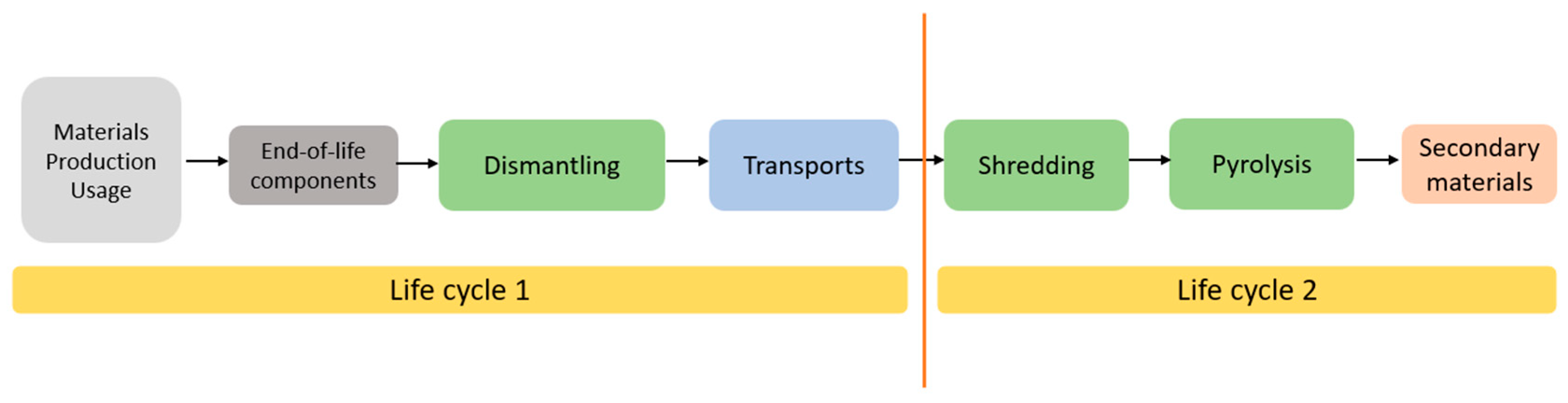
Following the commonly used cut-off approach, visualised in Figure 1, the environmental burdens allocated to the component’s first life cycle are materials, production, usage, dismantling and transport to the recycling facility (see life cycle 1 in Figure 1). The processing steps such as shredding and pyrolysis are allocated to the secondary material’s life cycle (life cycle 2 in Figure 1). The impact of life cycle 1 for the side skirts and the header, and life cycle 2 (recycling of the components) were calculated separately. In this study, the focus was on life cycle 2, and the corresponding analysis is presented in the following sections.
In this paper, the functional units for the header and the side skirts were defined as follows:
  • One kilogram of dismantled composite no. 1 (side skirt) made of NF/PP subjected to pyrolysis
  • One kilogram of dismantled composite no. 2 (side skirt) made of NF/PA11 subjected to pyrolysis
  • One kilogram of dismantled composite no. 3 (header) made of SMC subjected to pyrolysis

3. Results

The composite samples were first characterised using TGA and analytical pyrolysis. Secondly, four of the samples were evaluated further in a laboratory pyrolysis system. Based on the laboratory tests on three of the composites (NF/PP, NF/PA11, and SMC), a comparison of the climate impact of EoL solutions was made.

3.1. Characterisation of Composite Materials

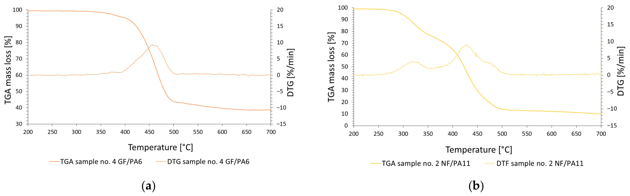
The thermogravimetric analysis determined the decomposition temperature of the different organics, based on which suitable pyrolysis temperatures for the upcoming laboratory experiments were determined. In Figure 2, two representative results from the thermogravimetric analysis, TGA and TGA-DTG (derived TGA measurements), are shown for samples 4 and 2 respectively.
In Figure 2a the results from the thermogravimetric analysis of the composite material containing glass fibre and PA6 can be found. PA6 decomposes between 400 and 500 °C, which means that 500 °C seems to be a good pyrolysis temperature for PA6-containing composites. Since the weight decrease stops at around 40 wt.%, this indicates the approximate glass fibre amount in the initial composite. In Figure 2b the TGA and TGA-DTG for sample no. 2, i.e., natural fibres and PA11, are shown. This composite has two main separate degradation temperature ranges, 280 to 350 °C and 360 to 500 °C. The first degradation temperature corresponds to the main component in the natural fibres; cellulose decomposes at 185–385 °C [12]. The second degradation temperature likely corresponds to the polymer PA11. Since the different types of materials decompose at different temperatures, one alternative is to perform the pyrolysis in two steps: first at a lower temperature, i.e., 350 °C, to collect the liquid generated by the cellulose, followed by pyrolysis at 500 °C to collect the liquid generated from the PA11. Similar analyses were conducted for the rest of the samples; based on the analyses, all decomposition temperatures were below 500 °C, which is why the pyrolysis temperature was chosen to be 500 °C for all samples. Sample no. 1 also had two degradation temperatures, but the degradation temperatures were overlapping, which means that it is not possible to differentiate the compounds by performing the pyrolysis at different temperatures.
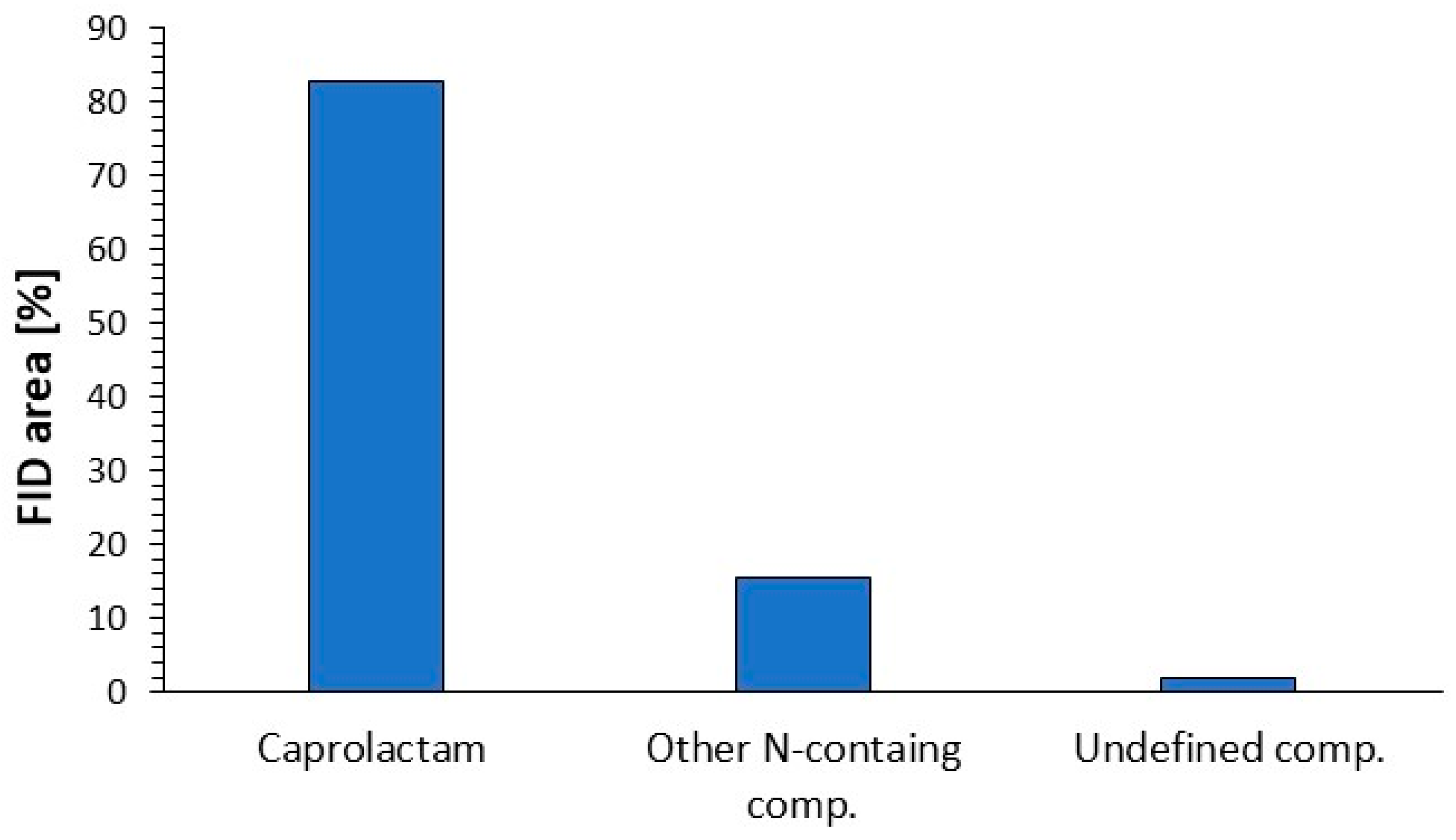
To further analyse the materials, the pyrolysis properties were evaluated on an analytical scale with PyGC/MS-FID. In Figure 3 the relative amount of volatile pyrolysis products from sample no. 4, glass fibres and PA6, can be seen. PA6 was mainly decomposed to Caprolactam, i.e., the monomer used to synthesise PA6. This indicates the potential to recover Caprolactam for the synthesis of new PA6. Even though the recycling of PA6 seemed promising, this material was not chosen for the demonstrators due to limited availability, at least within the time frame and budget of the project.
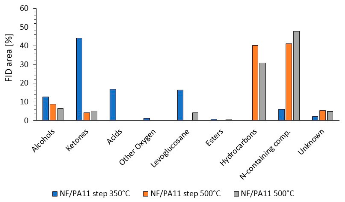
Since the TGA of sample 2 indicated that two separate decomposition temperatures were obtained, the analytical pyrolysis of the same composite was performed both stepwise at first 350 °C and then at 500 °C, and in one step at 500 °C (see Figure 4). As indicated by the composition of the pyrolysis vapours produced during the stepwise pyrolysis, the pyrolysis products from the original composite NF/PA11 can be separated into products originating from the natural fibres and from the PA11. The pyrolysis products decomposed at 350 °C were mainly composed of ketones, alcohols, acids and levoglucosan, i.e., resulting from the natural fibres, while the products decomposed between 350 and 500 °C were mainly composed of hydrocarbons with and without nitrogen in the form of 1-hexene and 9-decentnitrile, originating from PA11. Gas chromatography can only analyse volatile compounds with a boiling point of less than around 300 °C, which means that the monomer the polymer PA11 is synthesised from cannot be detected via this analysis.

3.2. Laboratory-Scale Pyrolysis Results

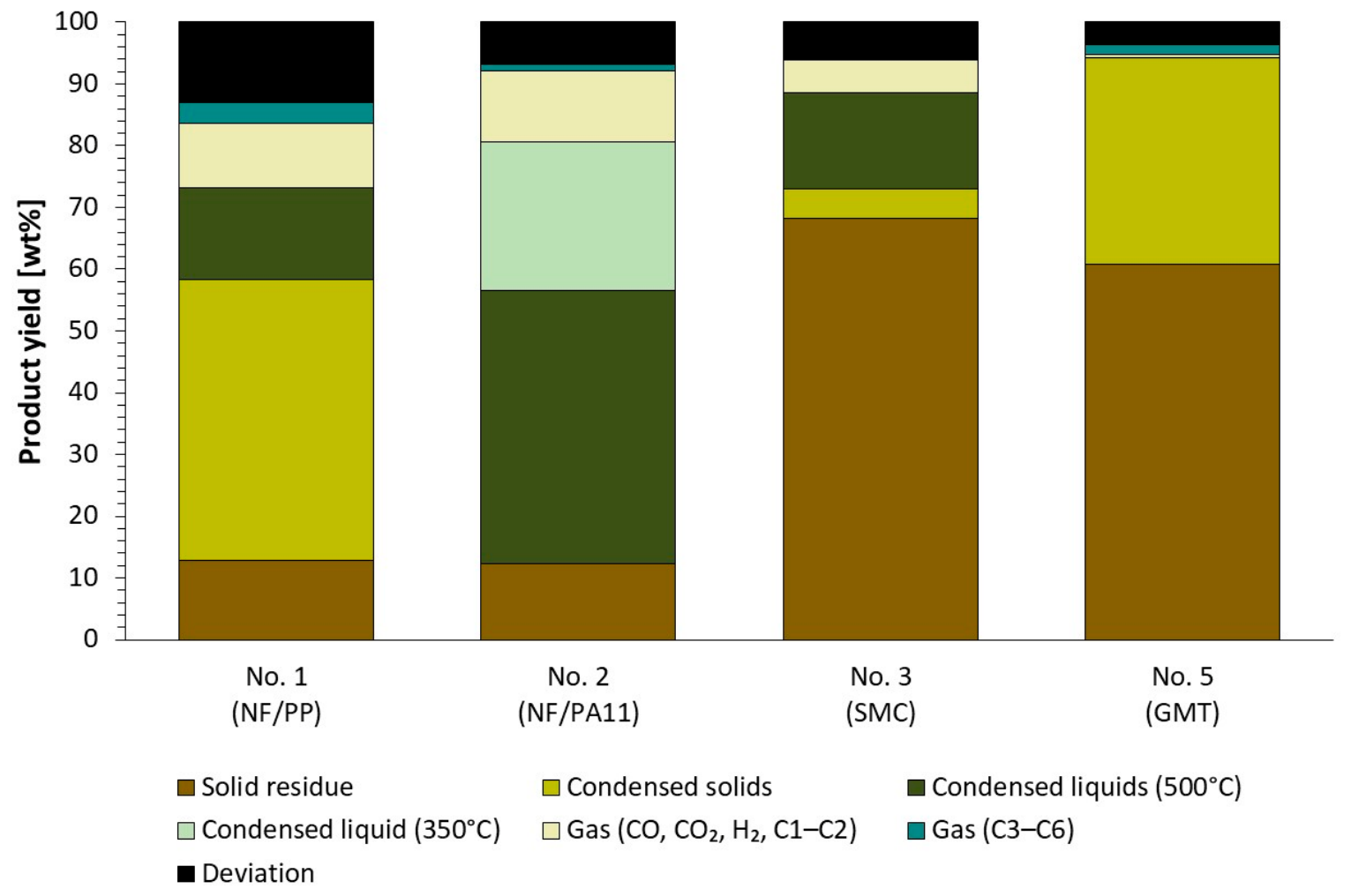
To verify the analytical measurements and to determine pyrolysis product yields and composition, four of the samples—sample nos. 1, 2, 3 and 5—were evaluated in a laboratory-scale batch pyrolysis setup. The mass balance for the four tests can be found in Figure 5.

3.2.1. Natural Fibres and PP

In Figure 5 the mass balance for the batch pyrolysis of natural fibres and PP, sample no. 1, at 500 °C is presented. The closure of the mass balance was approximately 87 wt.%. The deviation can be due to the fact that not all gas components were detected/analysed in the non-condensable gas. The composite material was mainly converted to condensed solids (45.6 wt.%), condensed liquid (14.8 wt.%), solid residue (10.5 wt.%), and non-condensable gas (10.5 wt.%), consisting of light gases (CO, CO2, H2 and C1–C2 hydrocarbons) and 3.2 wt.% heavier gases (C3 to C6). Based on the gas composition, the energy content was calculated to 2.4 MJ/kg sample.
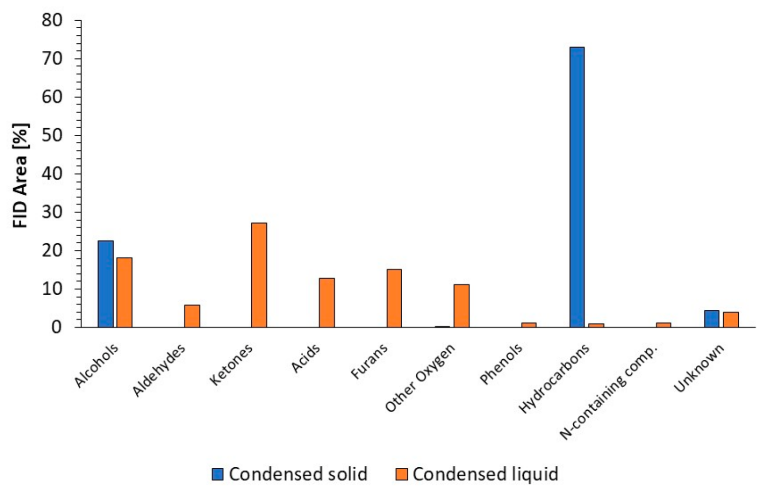
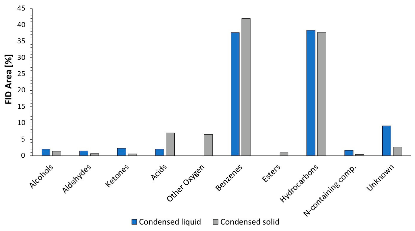
The pyrolysis products were characterised based on their elemental composition and heating value (see Table 2), and the volatile organic content in the condensed products was analysed by gas chromatography (see Figure 6). Even though the pyrolysis was done in one step, the different components from the two materials were separated into two phases. The decomposition compounds from the natural fibres, i.e., alcohols, aldehydes, ketones, acids and furans, ended mainly up in the condensed liquid, while the PP formed condensed solids (wax), which were mainly composed of hydrocarbons. Based on the chemical composition, the pyrolysis liquid contains a comparatively high content of water, low content of carbon and high content of oxygen, while the pyrolysis solid mainly contains carbon and hydrogen and therefore has a high heating value. The solid residue has a relatively high heating value and can be used for internal heat recovery.

3.2.2. Natural Fibres and PA11

In Figure 5, a mass balance for the batch pyrolysis of natural fibres and PA11 (sample no. 2) can also be found. The pyrolysis was run stepwise, i.e., first heated to 350 °C until the production of pyrolysis gas ceased. The condensed liquid was collected and denoted as condensed liquid (350 °C). Thereafter, the reactor was heated to 500 °C and kept at that temperature until the production of pyrolysis gas ceased; thereafter, the experiment was shut off and left to cool to room temperature with a nitrogen flow. The condensed liquid from the second step was collected and denoted as condensed liquid (500 °C).
The closure of the mass balance was considered to be high, i.e., at 93.2 wt.%. The composite material was mainly converted to liquid; 24.0 wt.% was collected after the first pyrolysis temperature at 350 °C, and another 44 wt.% was collected at the second pyrolysis temperature of 500 °C. The remaining products were obtained as solid residue (12 wt.%) and non-condensable gas (11.6 wt.% light gases: CO, CO2, H2 and C1–C2 hydrocarbons) and 1.0 wt.% heavier gases (C3 to C6). Based on the gas concentrations, the energy content in the gas was calculated to be 1.3 MJ/kg sample.
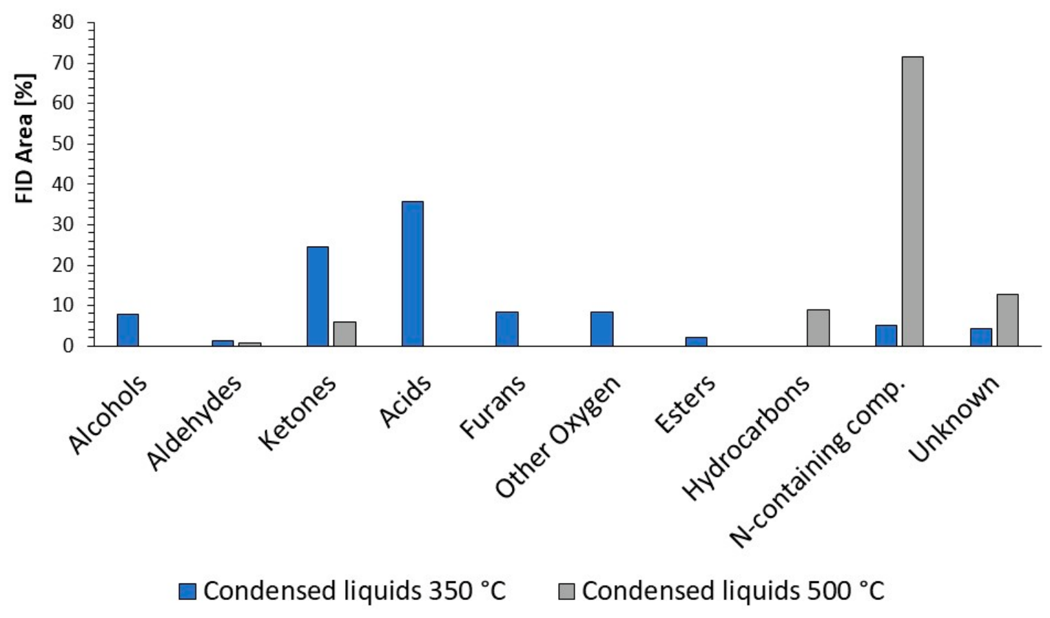
The composition of the pyrolysis liquids was analysed in terms of water content, elements, heating value and volatile organic content using gas chromatography, while the solid residue was analysed for elements and heating value. The results from the analyses can be found in Table 3 and Figure 7. Similar to the results from the analytical pyrolysis, the liquid generated at 350 °C contained decomposition products from the natural fibres, i.e., it contains alcohols, ketones, acids and furans. This liquid is an aqueous fraction that contains highly oxygenated compounds with a low heating value. The liquid produced at 500 °C is instead composed of different types of hydrocarbons and nitrogen-containing compounds, with a rather high heating value. The solid residue also has a rather high heating value, which means that it can be used to recover some heat for the pyrolysis. The pyrolysis liquid collected at a pyrolysis temperature of 350–500 °C contained degradation products of PA11. Since the gas chromatography analysis only characterises the volatile part of the sample, further analysis using both TGA and attenuated total reflection in conjunction with infrared spectroscopy (ATR-IR) was conducted. The results from the TGA can be seen in Supplementary Materials Figure S1, and the spectrum from the ATR-IR can be seen in Supplementary Materials Figure S2. Based on the TGA, at 20–120 °C, the generation of smaller decomposition products such as alcohols, ketones and water caused an erratic decrease in sample weight. From 120 to 500 °C, there was steady weight loss with no visible steps, indicating a mixture of compounds with varying boiling points over the temperature range. To further evaluate the composition and similarity with PA11, an ATR-IR analysis was performed. The spectrums from the dried condensed liquid were compared with PA11. The patterns were relatively similar, indicating that there is a high probability that the liquid can be used for re-polymerisation to form PA11.

3.2.3. SMC

The mass balance for the pyrolysis of the reference composite composed of glass fibres and polyester (SMC) is shown in Figure 5. The closure of the mass balance was high, at 94 wt.%. As can be seen in the figure, the main product was the solid residue, at 68 wt.%. This product included, besides glass fibres, calcium carbonate, which is usually found as a filler in SMC materials, and a small amount of deposits/char. The condensed pyrolysis products were preset in both liquid and solid form. Both the condensed solid and liquid were analysed by means of gas chromatography (Figure 8), and the liquid was analysed for water, elemental composition and heating value (Table 4). The different types of condensed products had a similar composition, mainly consisting of aromatic and linear hydrocarbons. The aromatic hydrocarbons were mainly composed of styrene.

3.2.4. GMT

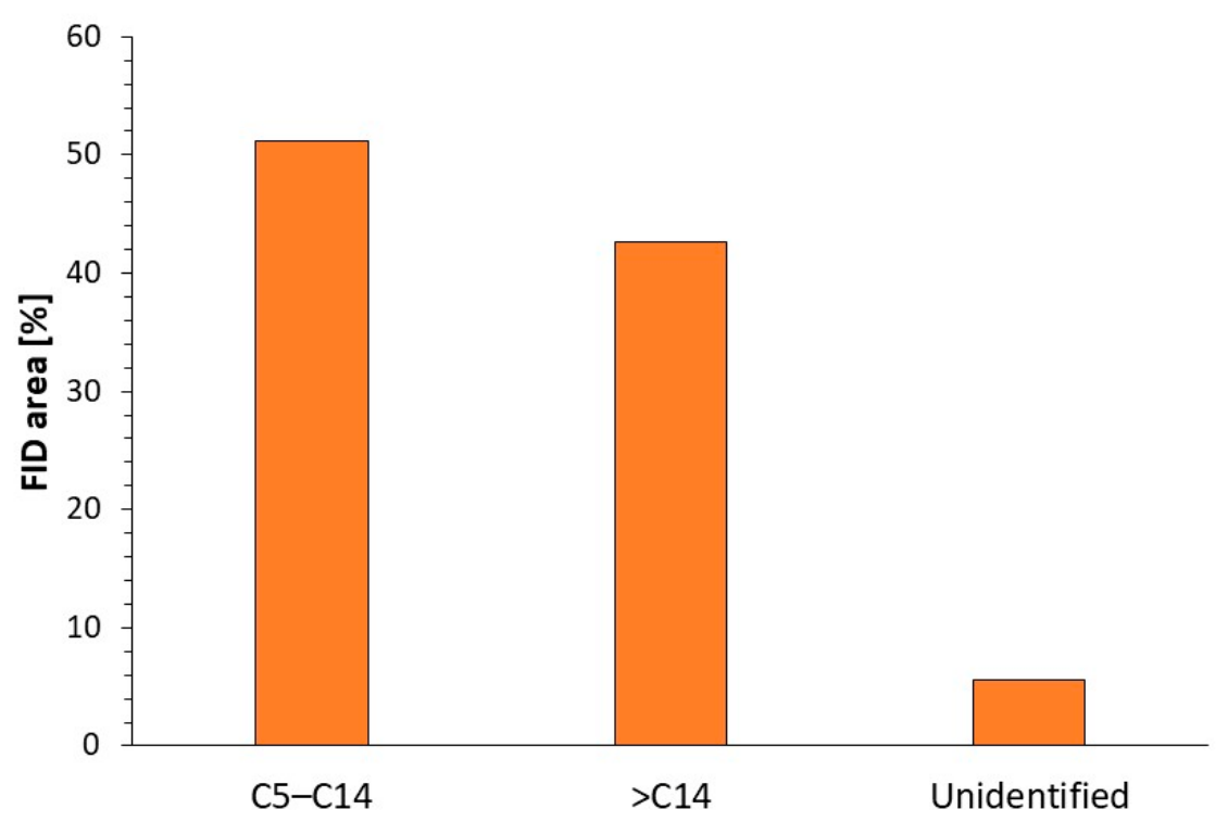
The mass balance for the composite containing glass fibre and PP (GMT), sample no. 5, is shown in Figure 5. This composite was mainly converted to solid residue and condensed solids. The solid residue contained mainly fibres and a small amount of deposits/char. The condensed solids were composed of hydrocarbons, alkenes and alkanes of various lengths (see Figure 9). In total, 51% of the FID area is in the range of C5–C14, while 43% of the FID area is above C15. The condensed solids were characterised by elements, ash and heating value, and the results can be found in Table 5. The carbon and hydrogen content were 86 wt.% (ds) and 16 wt.% (ds) respectively. This type of stream can be cracked in the chemical industry, i.e., for the production of new polyolefins.

3.2.5. Energy Requirements

Pyrolysis of composite materials is an endothermic reaction, which means that energy input is required for the reaction. In Table 6, energy balances for three of the pyrolysis runs can be found. The required energy for the pyrolysis of the three cases varied between 3.7 and 5.7 MJ/kg of composite. For more information about the calculations, see Supplementary Materials File S2. These numbers are in the same range as reported previously in the literature, i.e., by Song et al. (2009) [13]. The higher energy requirement for the natural fibres and PA11 can be related to the fact that the pyrolysis was run stepwise, while the other pyrolysis tests were just run at one temperature. The required energy for pyrolysis can be covered, at least to some extent, by the combustion of the byproducts, i.e., the non-condensable gas and/or the solid residue. For the composite containing natural fibres, there is a relevant amount of energy in both the solid residue and the non-condensable gas. For the traditional glass fibre and thermoset resin and PP, only a limited amount of energy can be obtained from the combustion of the gas. However, the yield and quality of the main pyrolysis products (pyrolysis liquid/solids and fibres) are in general higher.

3.3. LCA

3.3.1. System Boundaries, Assumptions and Requirements

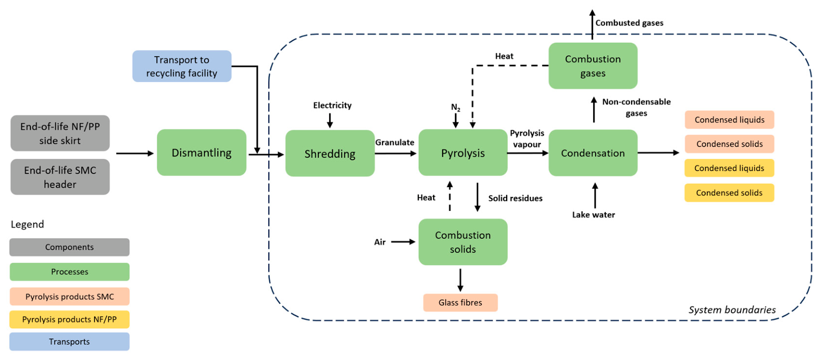
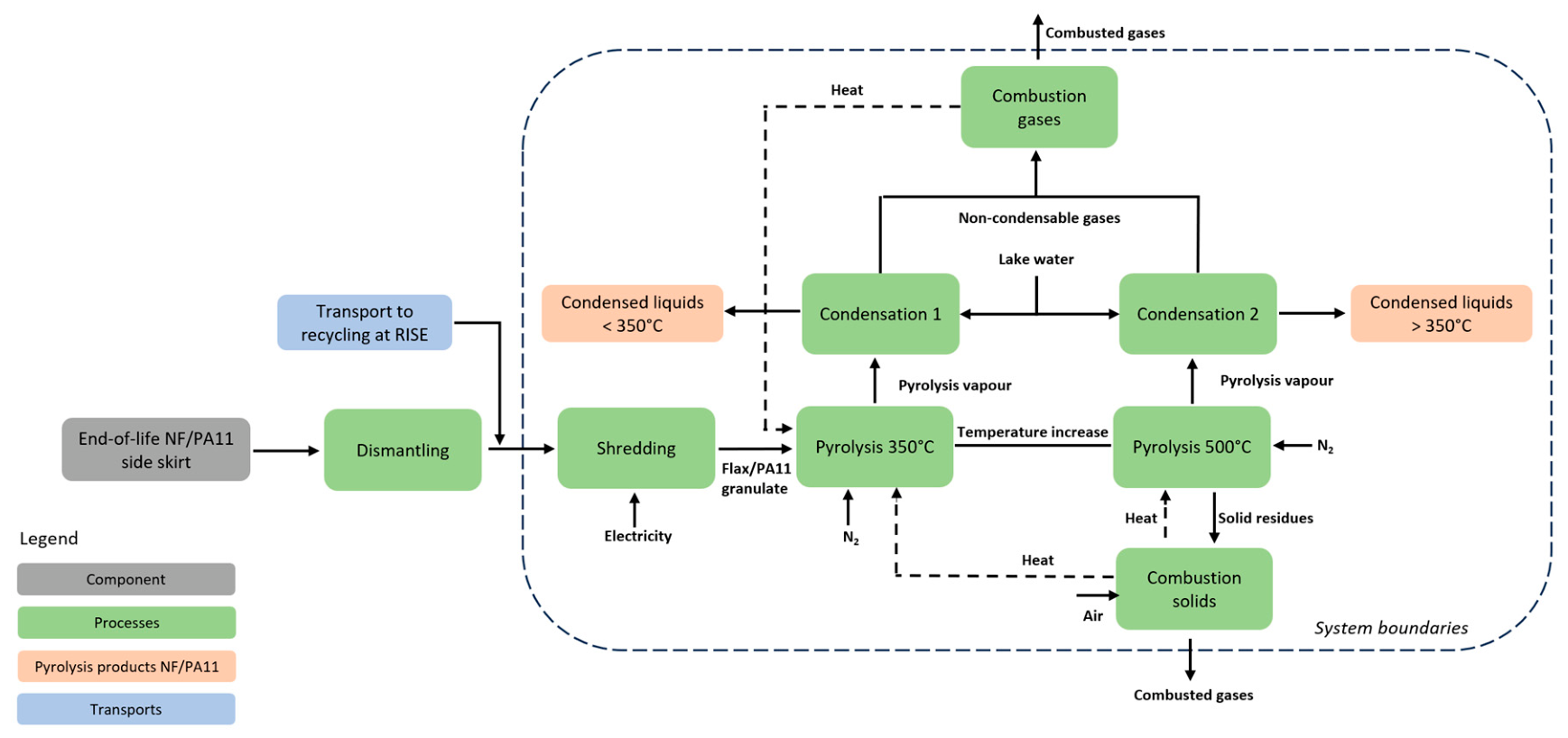
The system boundaries considered for the EoL treatment in the LCA include shredding, pyrolysis, condensation of pyrolysis vapours and combustion of the byproducts, solid residue and non-condensable gases, and are shown in Figure 10 and Figure 11, respectively. The pyrolysis steps for the NF/PP side skirt and the SMC header were identical; therefore, they are presented together in a single figure (Figure 10), although the pyrolysis was performed separately for each material. The NF/PA11 side skirt followed a slightly different pyrolysis sequence and is presented in Figure 11.
The following assumptions and limitations were made in the LCA:
  • Primary data for the pyrolysis process was based on a non-optimised small-scale laboratory experiment, which should be kept in mind while interpreting the LCA results
  • During the pyrolysis process, nitrogen was supplied in gaseous form. However, the LCA model is based on the use of liquid nitrogen
  • Biogenic carbon dioxide was assumed to be released during the combustion of solid residues and gases in the NF/PA11 solutions, since both components originate from natural, bio-based sources
  • For the NF/PP solution, both biogenic and fossil carbon dioxide emissions were assumed to be released (50/50 distribution). This assumption reflects that the NF is bio-based, whereas PP is a fossil-derived polymer
  • Water use was not modelled in the study
  • Waste generated during the shredding of all components and after the pyrolysis process step for the side skirts was assumed to be incinerated
  • The oxidation step to remove the char from the glass fibres after the pyrolysis process was not included in the study
  • The following replacement rates were assumed, based on LHV for the solid and liquid components:
    ○
    For the SMC header: 1 kg of condensed solid and 1 kg of condensed liquid replaced 1 kg of hydrocarbon in both cases. 1 kg of pyrolysed glass fibres replaced 0.5 kg of virgin glass fibres
    ○
    For the NF/PP side skirt: 1 kg of condensed liquid (bio-oil), which can be used as input components for biofuel production, i.e., petrol, was assumed to replace approximately 0.1 kg of petrol. Furthermore, 1 kg of condensed solid replaced 1 kg of naphtha
    ○
    For the NF/PA11 side skirt: 1 kg of condensed liquid (bio-oil) from NF replaced 0.1 kg of petrol, and 1 kg of condensed liquid from PA11 replaced 0.5 kg of naphtha
  • The extra energy added into the pyrolysis recycling of the NF/PA11 side skirt and SMC header was assumed to serve the pyrolysis reactor in the form of electricity (Swedish mix).
  • The excess energy generated after the pyrolysis of the NF/PP side skirt was assumed to replace district heating from natural gas.
The data quality of the study was assessed considering the aspects of time-related coverage, technology-related coverage, geographical coverage, precision, completeness, consistency, reproducibility, representativeness, and uncertainty of the information, as described in ISO 14044 [9]. An evaluation of the data quality is presented in the Supplementary Materials File S3.

3.3.2. Inventory Analysis

The inventory analysis was based on primary data collected from RISE. When no primary data was available, generic data from Ecoinvent version 3.10 was used [14], and in some cases, it was complemented by other literature sources. Primary data for the pyrolysis process was sourced from RISE, based on the small-scale pyrolysis experiment presented in this paper (and not the industrial-scale process), which should be kept in mind while interpreting results. The primary data was collected in the years 2023–2025, representing the year 2023. Average country data from Ecoinvent was used when the country was known. When no specific origin was known, global market data was selected.
Prior to the pyrolysis process, the considered materials were assumed to undergo the same size-reduction procedure, namely shredding. The energy consumption for shredding each type of material was calculated based on data from [15].
The LCA inventory for the pyrolysis of 1 kg of the NF/PP side skirt can be found in Supplementary Materials Table S7. The condensed liquid generated from the fibres can be utilised as input component for biofuel production (petrol) while the condensed solid from PP can be used to replace naphtha, an intermediate product in the petrochemical industry. Excess heat (1537 kJ) was also generated after the process.
The LCA inventory for the pyrolysis of 1 kg of the NF/PA11 side skirt can be found in the Supplementary Materials Table S8. To separate condensed pyrolysis products from the fibres and the PA11, the pyrolysis was performed stepwise, first at a temperature of 350 °C to collect the pyrolysis liquid generated from the fibres, followed by pyrolysis at 500 °C to generate pyrolysis liquid from the PA11. Similar to the NF/PP pyrolysis products, the biooil from the fibres can be utilised as an input component for biofuel production for transportation fuel (petrol), while the biooil from PA11 can be used as an intermediate in the petrochemical industry.
The LCA inventory for the pyrolysis of 1 kg of the SMC material can be found in Table S9. The polymeric part from SMC partly formed a condensed liquid and partly a condensed solid that both can be used as intermediates in the petrochemical industry (replacing fossil hydrocarbons and aromatics). The glass fibres, including the filler in the SMC (calcium carbonate), together with some char, end up as solid residues.

3.3.3. Impact Assessment

The focus of this paper was on climate impact, which was calculated in terms of global warming potential over a 100-year timeframe, where emissions of different greenhouse gases, primarily CO2, nitrous oxide (N2O) and methane (CH4), are converted into carbon dioxide equivalents (CO2-eq) using characterisation factors [16]. There are different versions of the GWP method, and in this paper, the IPCC (2021) method was applied (called IPCC 2021 GWP 100 version 1.03 in SimaPro, version 10.3.0.1), where fossil CO2, N2O and fossil CH4 have characterisation factors of 1, 273 and 29.8 kg CO2-eq per kg gas, respectively [17]. The method implemented in SimaPro also considers biogenic methane and permanent carbon loss from land use as fossil CO2. The results in this report are presented as total climate impact, i.e., including fossil, biogenic and land use emissions.
NF/PP Side Skirt
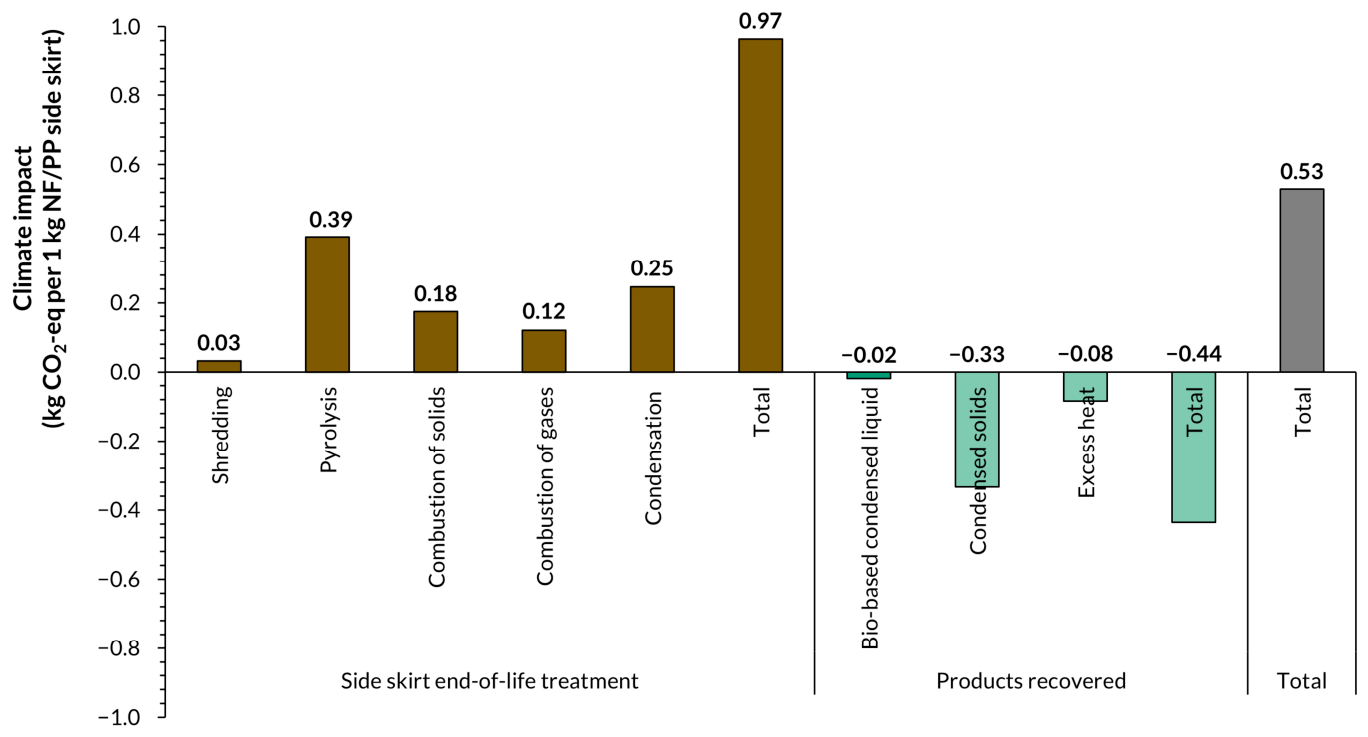
The results presented in Figure 12 show the climate impact of the recycling processes at EoL, the climate impact of the potentially avoided production of functionally equivalent products, and the total score. The total climate impact associated with the EoL treatment of 1 kg of NF/PP side skirt was 0.97 kg CO2-eq. The largest contribution originated from the pyrolysis process (41%), followed by condensation (25%), combustion of solids (18%), combustion of gases (13%) and shredding (3%). The negative climate impact of –0.44 kg CO2-eq is attributed to:
  • the avoided production of naphtha, as the recovered condensed solids from PP serve as an intermediate feedstock in that production
  • the avoided production of petrol, as the recovered bio-based condensed liquid from NF serves as an intermediate feedstock in the biofuel production
  • the excess heat generated during the pyrolysis of PP
NF/PA11 Side Skirt
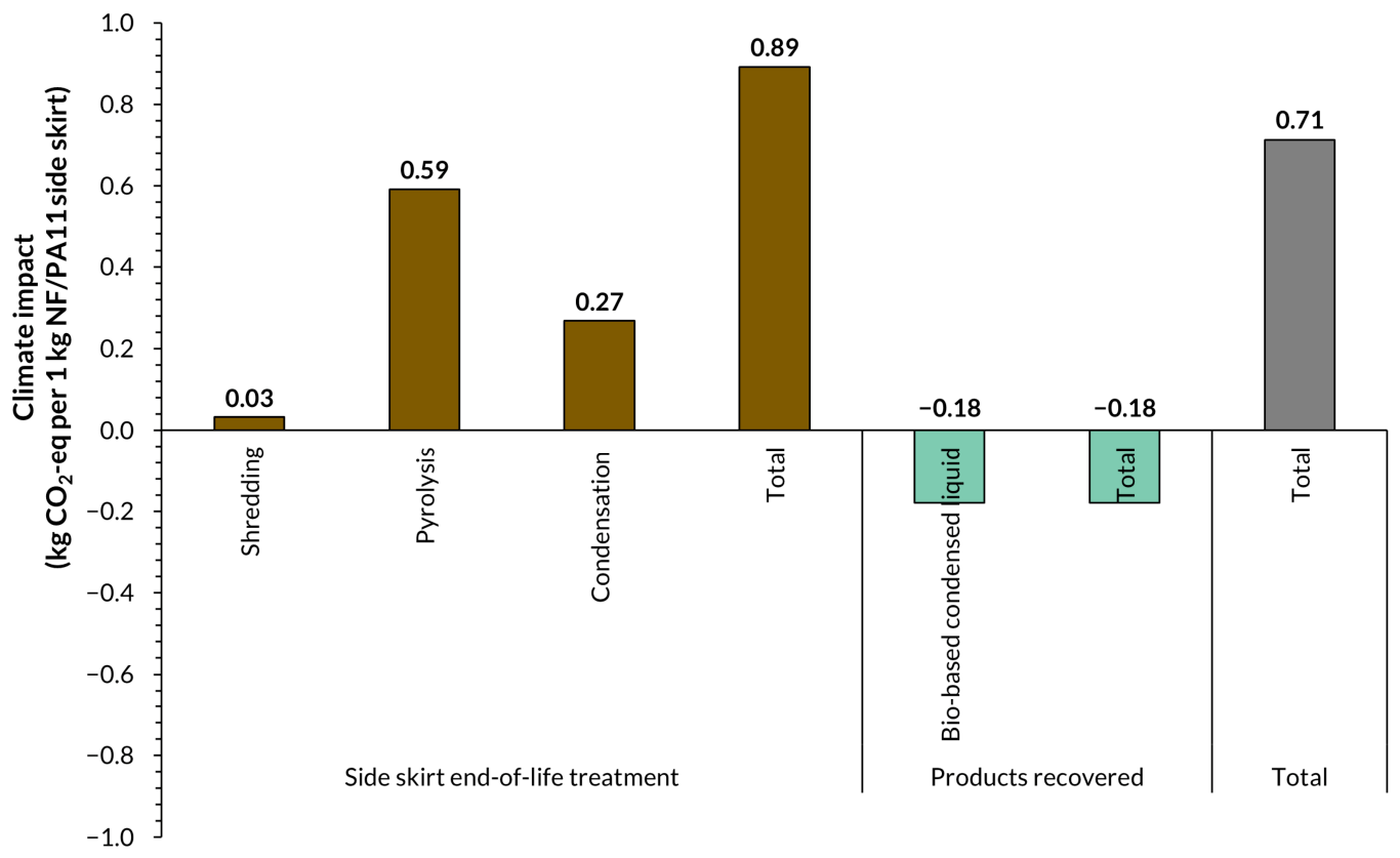
The results presented in Figure 13 show the climate impact of the recycling processes at EoL and the climate impact of the potentially avoided production of functionally equivalent products and the total score. The total climate impact associated with the end-of-life treatment of 1 kg of NF/PA11 side skirt was 0.89 kg CO2-eq. The largest contribution originated from the pyrolysis process (66%), followed by condensation (30%) and shredding (4%). The total negative climate impact of –0.18 kg CO2-eq is attributed to the avoided production of petrol, as the bio-based condensed liquid derived from NF and PA11 fractions functions as an intermediate feedstock in that process.
SMC Header
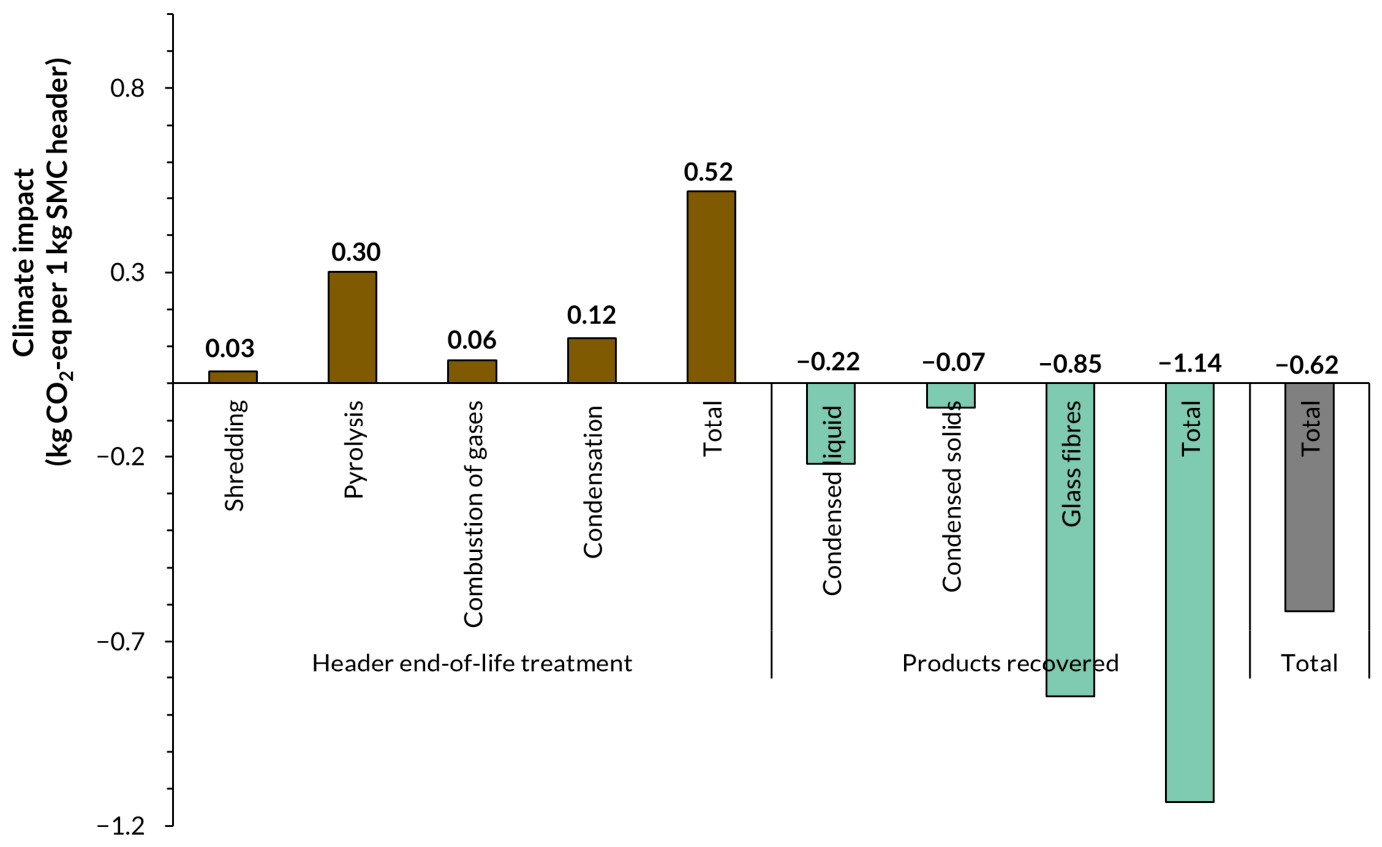
The total climate impact for 1 kg of the reference SMC header was −0.62 kg CO2-eq, see Figure 14. This value reflects on the direct emissions from the end-of-life processes (0.52 kg CO2-eq) and the avoided impacts from the substitution of conventionally produced aromatics and glass fibres (−1.14 kg CO2-eq). The avoided production of these secondary materials, especially glass fibres (75% reduction of climate impact compared to the other products recovered), constitutes the largest contribution to the overall reduction in climate impact. It should be noted that we chose to reduce the substitution rate for glass fibres to 50%, due to the decreased fibre length and impurities obtained after pyrolysis.
Comparison
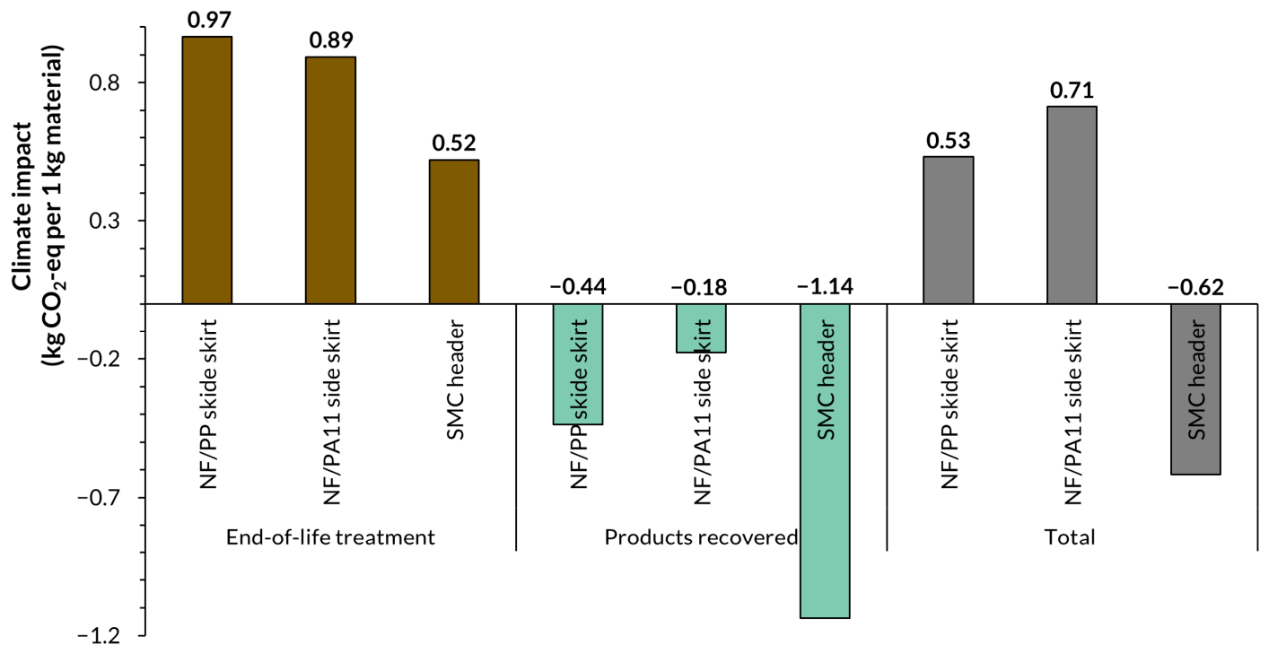
When comparing the three investigated components (Figure 15), clear differences emerge regarding both the direct climate impacts from EoL processing and the magnitude of the avoided impacts from secondary material recovery.
The NF/PP and NF/PA11 side skirts exhibit positive total climate impacts from the EoL processes, amounting to 0.97 kg CO2-eq and 0.89 kg CO2-eq, respectively. In both cases, the pyrolysis process step contributes the most, accounting for 41% of the impacts for NF/PP and 66% for NF/PA11. The higher climate impact of the pyrolysis of the NF/PA11 can be related to a stepwise pyrolysis approach, requiring more energy. Condensation is the second-largest contributor for both materials, while additional processes such as solid combustion (NF/PP) and shredding (NF/PA11) contribute to a lesser extent.
Both materials show negative climate impacts associated with substitution effects. For NF/PP, these avoided impacts total −0.44 kg CO2-eq, driven primarily by avoided naphtha and petrol production, as well as excess heat recovery. For NF/PA11, the avoided impact is lower (−0.18 kg CO2-eq), stemming from the bio-based condensed liquids that substitute petrol production.
In contrast, the SMC header shows an overall negative climate impact of −0.62 kg CO2-eq, making it the only component with a beneficial total climate impact result. Although the direct emissions from its EoL treatment are comparatively high (0.52 kg CO2-eq), the substitution benefits (−1.14 kg CO2-eq) compensate for these emissions. The avoided production of glass fibres contributes 75% to this compensation, even though the substitution rate is limited to 50%. The lower rate is due to the shortened fibre length and impurities obtained in conjunction with the laboratory-scale pyrolysis process.

4. Discussion

Different types of composites, including thermoplastic (PA6, PA11 and PP) and thermoset (polyester) resins and glass or natural fibres, were characterised and evaluated via laboratory-scale batch pyrolysis tests. It was found that the different materials significantly affected the outcome of both the composition of the pyrolysis products and the potential for recycling. In the text below, the different components are discussed separately.

4.1. Recycling of Fibres After Pyrolysis

The glass fibres can be recovered after pyrolysis. The pyrolysed glass fibres are black due to residues of char and carbonaceous material from the polymers, which can impact their mechanical performance and surface defects. The char is usually removed by subsequent oxidation. Post-oxidation has even proven to be beneficial from a glass quality point of view since the fibre strength can be restored [18]. By reusing the glass fibres in new composite applications, material circularity can be improved.
Unlike glass fibres, natural fibres cannot be recycled as fibres after pyrolysis, because they decompose at high temperatures (<400 °C). However, the fibres can be recovered as a bio-based pyrolysis liquid that for example can be used for biofuel production [19]. However, when pyrolysing natural fibre-based composites, the pyrolysis liquid will be composed of a mixture of decomposition products from both the fibres and the polymers, complicating the recovery and increasing treatment costs. Nevertheless, this study validated that separation of the different pyrolysis products can be achieved either directly in the pyrolysis process by utilising stepwise pyrolysis and collecting the different fractions separately or through post-treatment by phase separation.

4.2. Recycling of the Polymers After Pyrolysis

Depending on the composition of the polymer in the composite, the recovery will vary. For example, PA6 decomposed to a large extent into its monomers, caprolactam, during analytical pyrolysis. Caprolactam can therefore potentially be recovered from the generated pyrolysis liquid. However, PA6 was not a thermoplastic chosen for the project due to limited availability and properties, which is why this compound was only evaluated on a smaller analytical scale. PA11 decomposed into a liquid with different lengths of hydrocarbon chains, with and without nitrile groups. The liquid contains similar chemical bonding as PA11, but depending on its diverse composition, recovery can be inefficient. PP decomposes into a waxy hydrocarbon-containing product. By changing the process conditions in the pyrolysis, such as increasing the vapour residence time or adding a catalyst, the wax can be cracked into a liquid that is easier to handle. Similar products are currently used as inputs in the chemical industry to replace fossil naphtha products in the production of new polyolefins. It is likely that the pyrolysis product will require some additional adjustments, such as hydrotreatment or cracking, to meet the requirements set by the chemical industry. Polyester decomposes into a mixture of straight and aromatic hydrocarbons that can be recovered as chemicals, such as styrene, in the petrochemical industry [20].

4.3. LCA Discussion

The results demonstrate that the climate performance of composite materials at EoL is strongly influenced by two factors: (1) the energy intensity and emissions of the recycling processes themselves, and (2) the substitution potential of the recovered secondary materials. For the NF/PP and NF/PA11 components, the pyrolysis process consistently emerges as the largest contributor to climate impact. Although both materials generate valuable liquid fractions, enabling avoided production of petrol, naphtha, and hydrocarbons, the magnitude of these avoided impacts does not fully compensate for the emissions from pyrolysis and condensation. As a result, both systems show a positive but relatively low EoL climate impact. This impact is still considerably smaller than that of more common FRP EoL options, such as incineration, which in some cases can account for 38% of total CO2 emissions depending on the FRP manufacturing technology and polymer matrix used [21]. In contrast, the SMC header benefits from a much stronger substitution effect, primarily due to the recovered glass fibres. Unlike the recovered components for petrol or naphtha, production of glass fibres requires more energy, and therefore, even a partial substitution (50%) leads to substantial avoided emissions, assuming that the recycled fibre quality is sufficiently high and that reuse processes are feasible for industrial use cases. This demonstrates that materials with high embodied energy can offer disproportionately large environmental benefits when recovered effectively, even if their recycling processes themselves are comparatively emission-intensive. It is also important to underscore that the magnitude of avoided emissions is highly sensitive to the selection of the virgin material to be displaced. In the present case, this selection was based on assumptions, and consequently the resulting estimates may deviate from real-world conditions. Another important observation is that the quality of recovered material plays a decisive role. For SMC, fibre length degradation and remaining impurities limit the substitution rate; yet even with this constraint, the avoided emissions exceed the direct EoL impacts.
Overall, the results underscore the importance of designing composite systems and recycling processes in tandem, ensuring both manageable EoL emissions and high substitution potential for recovered materials.

5. Conclusions

Recycling of different types of composites, including thermoplastic (PA6, PA11 and PP) and thermoset (polyester) resins and glass or natural fibres, have been performed via laboratory-scale pyrolysis and evaluated both technically and environmentally. The considered composite materials affected the pyrolysis outcome differently. Glass fibres have the potential to be recovered and reused as fibres, while natural fibres can be recovered as bio-oil that potentially can be utilised in biofuel production. The polymers were recovered as pyrolysis products that, depending on their composition, can be used in different applications, from the recovery of chemical monomers (PA6) to the replacement of naphtha (PP) or aromatics (polyester) in the petrochemical industry.
The LCA findings show that the EoL climate performance of composite materials is primarily determined by the emissions from recycling processes and the substitution potential of recovered materials. For NF/PP and NF/PA11, pyrolysis has the highest climate impact, and the avoided emissions from recovered liquids are insufficient to compensate for the high processing emissions. In contrast, the SMC header shows considerably higher climate benefits due to the recovery of energy-intensive glass fibres, even with a reduced substitution rate. The results also indicate that avoided emissions are highly sensitive to the assumed replaced virgin material, and assumption-based choices introduce uncertainty. Overall, the study underscores the need to design composite products and recycling strategies together to achieve lower EoL impacts and maximise the value of recovered materials.

Supplementary Materials

The following supporting information can be downloaded at https://www.mdpi.com/article/10.3390/cleantechnol8020059/s1. Figure S1. TGA curve of condensed liquid (500 °C) from natural fibres and PA11, sample no. 2; Figure S2. ATR-IR spectra of PA11 (red) and dried (at 105 °C for 24 h) condensed liquid (500 °C) generated from sample no. 2 (natural fibres and PA11) (black); Figure S3. Furnace power output (E out) and furnace temperature (Temp. furnace) versus time. (a) indicates the power output when the temperature in the furnace reaches steady state; (b) indicates the calculated heat losses (Q loss) of the furnace over time, and the actual energy provided to the pyrolysis, i.e. the area between the furnace power output and the heat losses, assuming 100 % efficiency of the furnace; Table S1. Composition and lower heating value of non-condensable gas from pyrolysis of NF/PP; Table S2. Composition and lower heating value of non-condensable gas from pyrolysis of NF/PA11; Table S3. Composition and lower heating value of non-condensable gas from pyrolysis of SMC; Table S4. Resources included in the study and their Ecoinvent dataset for pyrolysis of 1 kg NF/PA11 side skirt; Table S5. Resources included in the study and their Ecoinvent dataset for pyrolysis of 1 kg NF/PP side skirt; Table S6. Resources included in the study and their Ecoinvent dataset for pyrolysis of 1 kg SMC header; Table S7. Inventory for pyrolysis of 1 kg of the NF/PP composite side skirt; Table S8. Inventory for pyrolysis of 1 kg of the NF/PA11 composite side skirt; Table S9. Inventory for pyrolysis of 1 kg of composite no. 3 (SMC header). (LHV = lower heating value).

Author Contributions

Conceptualization, A.-C.J. and M.J.; methodology, T.H. and M.J.; validation, M.J.; formal analysis, M.J.; investigation, A.S. and R.N.; data curation, R.N.; writing—original draft preparation, A.-C.J. and M.J.; writing—review and editing, J.E.; visualization, A.-C.J., A.S., T.H. and M.J.; supervision, A.-C.J.; project administration, A.-C.J.; funding acquisition, J.E. and A.-C.J. All authors have read and agreed to the published version of the manuscript.

Funding

This research was funded by the Swedish Energy Agency, grant number 2021-00366.

Data Availability Statement

The original contributions presented in this study are included in the article/Supplementary Material. Further inquiries can be directed to the corresponding author.

Acknowledgments

During the preparation of this manuscript/study, the author(s) used [M 365 Copilot] (version 19.2604.33111.0) for the purposes of grammatical improvement. The authors have reviewed and edited the output and take full responsibility for the content of this publication.

Conflicts of Interest

Authors Ann-Christine Johansson, Rebecka Nordsvahn, André Selander, Torun Hammar, Jesper Eman and Magdalena Juntikka were employed by the Research Institute of Sweden AB. All authors declare no conflicts of interest. The funders had no role in the design of the study; in the collection, analyses, or interpretation of data; in the writing of the manuscript; or in the decision to publish the results.

Abbreviations

The following abbreviations are used in this manuscript:
ATRAttenuated total reflection
DSDry substance
DTGDerived thermogravimetric
EoLEnd-of-life
FIDFlame ionisation detector
FRPFibre reinforced polymers
GCGas chromatography
GFGlass fibres
GMTGlass mat reinforced thermoplastic
GWPGlobal warming potential
HHVHigher heating value
IRInfrared
LCALife cycle assessment
LHVLower heating value
PAPolyamide
PPPolypropylene
MSMass spectrometer
NFNatural fibre
OEMOriginal equipment manufacturer
SMCSheet moulding compound
TCDThermal conductivity detector
TGAThermogravimetric analysis

References

  1. Greenhouse Gas Emissions from Transport in Europe. 2025. Available online: https://www.eea.europa.eu/en/analysis/indicators/greenhouse-gas-emissions-from-transport?activeAccordion= (accessed on 22 December 2025).
  2. Das, P.K.; Bhat, M.Y.; Sajith, S. Life cycle assessment of electric vehicles: A systematic review of literature. Environ. Sci. Pollut. Res. Int. 2024, 31, 73–89. [Google Scholar] [CrossRef] [Scilit] [PubMed]
  3. Yan, L.; Xu, H. Lightweight composite materials in automotive engineering: State-of-the-art and future trends. Alex. Eng. J. 2025, 118, 1–10. [Google Scholar] [CrossRef] [Scilit]
  4. Juntikka, M.; Engberg, D.; Aitomäki, Y.; Hammar, T. Life cycle assessment of lightweight natural fibre/PP-composite side skirts for electric trucks. Clean. Environ. Syst. 2026, 20, 100393. [Google Scholar] [CrossRef] [Scilit]
  5. Xue, X.; Liu, S.Y.; Zhang, Z.Y.; Wang, Q.Z.; Xiao, C.Z. A technology review of recycling methods for fiber-reinforced thermosets. J. Reinf. Plast. Compos. 2022, 41, 459–480. [Google Scholar] [CrossRef] [Scilit]
  6. Oliveux, G.; Dandy, O.L.; Leeke, A.G. Current status of recycling of fibre reinforced polymers: Review of technologies, reuse and resulting properties. Prog. Mater. Sci. 2015, 72, 61–99. [Google Scholar] [CrossRef] [Scilit]
  7. Li, M.; Pu, Y.; Thomas, V.M.; Yoo, C.G.; Ozcan, S.; Deng, Y.; Nelson, K.; Ragauskas, A.J. Recent advancements of plant-based natural fiber–reinforced composites and their applications. Compos. Part B Eng. 2020, 200, 108254. [Google Scholar] [CrossRef] [Scilit]
  8. ISO 14040:2006; Environmental Management—Life Cycle Assessment—Principle and Framework. ISO: Geneva, Switzerland, 2006.
  9. ISO 14044:2006; Environmental Management—Life Cycle Assessment—Requirements and Guidelines. ISO: Geneva, Switzerland, 2006.
  10. Project Information Ground Zero. Available online: https://www.energimyndigheten.se/forskning-och-innovation/data-om-finansiering-av-forskning-och-innovation/projektdatabas/sokresultat/?registrationnumber=2021-200758 (accessed on 18 February 2026).
  11. Johansson, A.C.; Selander, A.; Soleimanisalim, A.H.; Nordsvahn, R.; Shafaghat, H. Chemical recycling of complex reject streams from the paper industry via thermal and catalytic pyrolysis. J. Anal. Appl. Pyrolysis 2024, 181, 106572. [Google Scholar] [CrossRef] [Scilit]
  12. Titok, V.; Leontiev, V.; Shostak, L.; Khotyleva, L. Thermogravimetric Analysis of the Flax Bast Fibre Bundle. J. Nat. Fibers 2006, 3, 35–41. [Google Scholar] [CrossRef] [Scilit]
  13. Song, S.Y.; Youn, R.J.; Gutowski, G.T. Life cycle energy analysis of fiber-reinforced composites. Compos. Part A Appl. Sci. Manuf. 2009, 40, 1257–1265. [Google Scholar] [CrossRef] [Scilit]
  14. Wernet, G.; Bauer, C.; Steubing, B.; Reinhard, J.; Moreno-Ruiz, E.; Weidema, B. The ecoinvent database version 3 (Part I): Overview and methodology. Int. J. Life Cycle Assess. 2016, 21, 1218–1230. [Google Scholar] [CrossRef] [Scilit]
  15. Bensadoun, F.; Vanderfeesten, B.; Verpoest, I.; Van Vuure, A.W.; Van Acker, K. Environmental impact assessment of end of life options for flax-MAPP composites. Ind. Crops Prod. 2016, 94, 327–341. [Google Scholar] [CrossRef] [Scilit]
  16. Myhre, G.; Shindell, D.; Bréon, F.-M.; Collins, W.; Fuglestvedt, J.; Huang, J.; Koch, D.; Lamarque, J.-F.; Lee, D.; Mendoza, B.; et al. Anthropogenic and Natural Radiative Forcing. In Climate Change 2013: The Physical Science Basis; Contribution of Working Group I to the Fifth Assessment Report of the Intergovernmental Panel on Climate Change; Coordinating Lead Authors: Gunnar Myhre (Norway), Drew Shindell (USA); Stocker, T.F., Qin, D., Plattner, G.-K., Tignor, M., Allen, S.K., Boschung, J., Nauels, A., Xia, Y., Bex, V., Midgley, P.M., Eds.; Cambridge University Press: Cambridge, UK; New York, NY, USA, 2013. [Google Scholar] [CrossRef] [Scilit]
  17. Forster, P.; Storelvmo, T.; Armour, K.; Collins, W.; Dufresne, J.-L.; Frame, D.; Lunt, D.J.; Mauritsen, T.; Palmer, M.D.; Watanabe, M.; et al. The Earth’s Energy Budget, Climate Feedbacks, and Climate Sensitivity. In Climate Change 2021: The Physical Science Basis; Contribution of Working Group I to the Sixth Assessment Report of the Intergovernmental Panel on Climate Change [Masson-Delmotte]; Cambridge University Press: Cambridge, UK; New York, NY, USA, 2021; pp. 923–1054. [Google Scholar] [CrossRef] [Scilit]
  18. Williams, T.P.; Cunliffe, A.; Jones, N. Recovery of value-added products from the pyrolytic recycling of glass-fibre-reinforced composite plastic waste. J. Energy Inst. 2005, 78, 51–61. [Google Scholar] [CrossRef] [Scilit]
  19. Dimitriadis, A.; Bergvall, N.; Johansson, A.C.; Sandström, L.; Bezergianni, S.; Tourlakidis, N.; Meca, L.; Kukula, P.; Raymakers, L. Biomass conversion via ablative fast pyrolysis and hydroprocessing towards refinery integration: Industrially relevant scale validation. Fuel 2023, 332, 126153. [Google Scholar] [CrossRef] [Scilit]
  20. Song, P.; Guo, S.; Zuo, M.; Wang, X.; Qiu, H.; Shen, B. A review on the catalytic pyrolysis of lipids to produce alternative aromatic hydrocarbons: Synthesis of hierarchically porous zeolites and aromatization mechanism. Circ. Econ. 2025, 4, 100128. [Google Scholar] [CrossRef] [Scilit]
  21. Ziemińska-Stolarska, A.; Sobulska, M.; Pietrzak, M.; Zbiciński, I. A Review of End-of-Life Scenarios for Fibre-Reinforced Polymer Materials. Energies 2024, 17, 3713. [Google Scholar] [CrossRef] [Scilit]
Figure 1. Visualisation of the cut-off approach, where the red line in the middle represents the border between the two life cycles.
Cleantechnol 08 00059 g001
Figure 2. Thermogravimetric analysis, TGA and TGA-DTG curves of (a) sample no. 4 comprising glass fibres and PA6 and (b) sample no. 2 comprising natural fibres and PA11.
Cleantechnol 08 00059 g002
Figure 3. Relative amounts of pyrolysis products derived from analytical pyrolysis of sample no. 4 containing glass fibres and PA6, expressed as a percentage of the detected FID area.
Cleantechnol 08 00059 g003
Figure 4. Relative amounts of pyrolysis products derived from the analytical pyrolysis of sample no. 2, containing natural fibres and PA11, expressed as a percentage of the detected FID area. The pyrolysis was performed both stepwise at 350 °C (denoted NF/PA11 step 300 °C), followed by 500 °C (NF/PA11 step 500 °C), and in one step at 500 °C (NF/PA11 500 °C).
Cleantechnol 08 00059 g004
Figure 5. Pyrolysis mass balances for the composite materials no. 1, 2, 3 and 5. The pyrolysis was done at 500 °C for sample nos. 1, 3 and 5, while stepwise pyrolysis was done for sample no. 2, at first at 350 °C, followed by 500 °C.
Cleantechnol 08 00059 g005
Figure 6. Relative amounts of organic compounds in the pyrolysis liquid and solid derived from natural fibres and PP (sample no. 1), grouped into chemical groups, expressed as a percentage of the detected FID area.
Cleantechnol 08 00059 g006
Figure 7. Relative amounts of organic compounds in the pyrolysis liquids derived from stepwise pyrolysis of natural fibres and PA11, grouped into chemical groups, expressed as a percentage of the detected FID area.
Cleantechnol 08 00059 g007
Figure 8. Relative amounts of organic compounds in the condensed pyrolysis liquid and solids derived from glass fibres and polyester (SMC), no. 3, grouped into chemical groups, expressed as a percentage of the detected FID area.
Cleantechnol 08 00059 g008
Figure 9. Relative amounts of organic compounds in the pyrolysis solids derived from glass fibres and PP, grouped by the number of carbons in the hydrocarbons chain.
Cleantechnol 08 00059 g009
Figure 10. Flow chart and the system boundaries of the EoL treatments (material preparation via shredding and recycling via pyrolysis) for the SMC header and the NF/PP side skirt. Grey denotes EoL components, green indicates processing steps. Peach represents pyrolysis products derived from SMC, while yellow indicates pyrolysis products from NF/PP. Blue denotes transport process.
Cleantechnol 08 00059 g010
Figure 11. Flow chart and the system boundaries of the EoL treatments (material preparation via shredding and recycling via stepwise pyrolysis) for the NF/PA11 side skirt. Grey denotes EoL component, green indicates processing steps. Peach represents pyrolysis products derived from NF/PA11, while blue denotes transport process.
Cleantechnol 08 00059 g011
Figure 12. Climate impact of 1 kg NF/PP side skirt undergoing end-of-life treatments (brown bars) and impacts from secondary materials (green bars) and total (grey bar).
Cleantechnol 08 00059 g012
Figure 13. Climate impact of 1 kg NF/PA11 side skirt undergoing end-of-life treatments (brown bars), impacts from secondary materials (green bars), and total score (grey bar).
Cleantechnol 08 00059 g013
Figure 14. Climate impact of 1 kg SMC header undergoing end-of-life treatments (brown bars), including impacts from secondary materials (green bars).
Cleantechnol 08 00059 g014
Figure 15. Comparison of the three components in terms of climate impact.
Cleantechnol 08 00059 g015
Table 1. Composition of the composite materials evaluated in this study.
Composite No.Composite CompositionAbbreviationSelected/
Evaluated for
Demonstrator
1Natural fibres (flax and hemp), PP 1 NF/PPTruck side-skirt
2Natural fibres (flax and hemp), PA11 2NF/PA11Evaluated for
truck side-skirt
3Glass fibres, thermoset polyester 3
(reference composite)
SMCEvaluated for
car front header
4Glass fibres, PA6 4GF/PA6Evaluated for
car front header
5Glass fibres, PPGMTCar front header
1 PP is fossil-based polypropylene. 2 PA11 is bio-based polyamide polymer produced by the polymerization of 11-aminoundecanoic acid (C11H23NO2). 3 Composite no. 3 is a reference thermoset-based composite composed of glass fibres and polyester sheet moulding component (SMC) with a glass fibre content of 38 wt.% and calcium carbonate fillers. 4 PA6 is a polyamide polymer produced from polymerization of caprolactam (C6H11NO).
Table 2. Chemical characterisation, elemental composition and higher and lower heating value respectively, (HHV and LHV), of the pyrolysis liquid and solids as well as solid residue from natural fibres and PP, sample no. 1.
Pyrolysis LiquidPyrolysis SolidSolid Residue
Water [wt.%]28.3--
C [wt.%, ds 1]27.076.974.7
H [wt.%, ds]9.113.53.36
N [wt.%, ds]0.360.410.61
O [wt.%, ds]62.78.9615.6
S [wt.%, ds]0.0130.0720.025
Cl [wt.%, ds]0.0240.012-
HHV [MJ/kg, ds]9.0537.527.5
LHV [MJ/kg, ds]
(calculated)
6.6636.026.8
1 ds—dry substance.
Table 3. Chemical characterisation of the pyrolysis liquid obtained at a pyrolysis temperature of 350 °C and 500 °C as well as solid residue from natural fibres and PA11, sample no. 2.
Pyrolysis Liquid
(350 °C)
Pyrolysis Liquid
(500 °C)
Solid Residue
Water [wt.%]28.83.6-
C [wt.%, ds 1]25.971.379.9
H [wt.%, ds]8.511.83.8
N [wt.%, ds]0.167.50.44
O [wt.%, ds]64.59.213.03
S [wt.%, ds]0.0160.0360.016
Cl [wt.%, ds]0.0320.0007-
HHV [MJ/kg, ds]5.4233.629.8
LHV [MJ/kg, ds]
(calculated)
7.1835.429.0
1 ds—dry substance.
Table 4. Chemical characterisation of the condensable liquid obtained at a pyrolysis temperature of 500 °C from glass fibres and polyester, sample no. 3, (SMC).
Condensed Liquid
Water [wt.%]-
C [wt.%, ds 1]85.5
H [wt.%, ds]16.3
N [wt.%, ds]0.055
O [wt.%, ds]1.09
S [wt.%, ds]0.002
Cl [wt.%, ds]0.01
HHV [MJ/kg, ds]43.64
LHV [MJ/kg, ds]
(calculated)
42.09
1 ds—dry substance.
Table 5. Chemical characterisation of the pyrolysis condensed solid obtained at a pyrolysis temperature of 500 °C from glass fibres and PP, sample no. 5.
Condensed Solid
Water [wt.%]-
C [wt.%, ds 1]85.5
H [wt.%, ds]16.34
N [wt.%, ds]0.055
O [wt.%, ds]1.085
S [wt.%, ds]0.002
Cl [wt.%, ds]0.01
HHV [MJ/kg, ds]<0.01
LHV [MJ/kg, ds]
(calculated)
43.638
1 ds—dry substance.
Table 6. Energy balance for the pyrolysis of sample nos. 1, 2 and 3, based on kg of composite.
Sample No. 1,
NF/PP
Sample No. 2,
NF/PA11
Sample No. 3,
SMC
Energy required for pyrolysis [MJ/kg]3.725.734.52
Energy for heating gas [MJ/kg]0.570.910.48
Energy received from combustion of gas [MJ/kg]2.401.310.17
Energy received from combustion of solid residue [MJ/kg]3.423.55-
Net energy [MJ/kg]1.54−1.77−4.83
Disclaimer/Publisher’s Note: The statements, opinions and data contained in all publications are solely those of the individual author(s) and contributor(s) and not of MDPI and/or the editor(s). MDPI and/or the editor(s) disclaim responsibility for any injury to people or property resulting from any ideas, methods, instructions or products referred to in the content.