1. Introduction
The electric vehicle (EV) has become an important aspect of reducing gasoline pollution to the atmosphere. Although EVs provide a possible solution to climate change, technology has drawbacks. The most widely used means of charging is a wired connection method; however, it does not support mobility, which could lead to various other safety problems. Hence, wireless power transfer (WPT) has been proposed as a potential route to enhance the electric vehicle charging system and mobility [
1]. Wireless power transfer technology has been upgraded into many different topologies that enable improved power transmission. Various research studies have determined which type of power transfer method would be efficient for EVs [
2]. Although the inductive power transfer (IPT) method was adapted in early designs, one major drawback of the technique is the small distance available for efficient power transfer.
The main technique currently adopted is the magnetic resonance between transmitter and receiver coils, thereby improving the air gap flexibility of WPT systems [
3]. Due to the need for increased efficiency, the coil design has been analyzed with profound scrutiny over the years. A square design has been adopted in many papers due to potentially improved performance, and this paper will adopt the round coil shape and compare it with the square coil shape used in the paper [
4]. In [
5], the authors compare a spiral-shaped coil to a square-shaped coil of the same size and the same current excitation. This paper will compare two spiral shape coils and a square coil with different dimensions and different current excitation parameters. Authors in [
5] showed circular and rectangular spiral coil designs with an analysis based on the power transfer efficiency for suitable coil and core structures. The understructure for the design requires a shape containing multiple turns. This increases the number of turns and strength of the magnetic field. Including tunable capacitive compensation in primary and secondary coils helps compensate for the reactive power of the system and thereby improves efficiencies [
6,
7].
The compensation techniques include four main topologies with respect to how the capacitors are connected: parallel-series (PS), parallel-parallel (PP), series-parallel (SP), and series-series (SS). The PS and PP topologies have some disadvantages, such as the need for an additional inductor to help regulate the inverter current. The ideal choices for the proposed systems used in this paper are the SS and SP topologies, which will enable the best efficiency and are the least complex due to their reduced component count compared to the parallel configurations. This paper utilizes the SS and SP configurations in analyzing the WPT system. The shape of the coil has also been investigated to show how it impacts the efficiency of the WPT system. Furthermore, the WPT system uses electromagnetic induction resonance to generate power. Although this method does not release more electromagnetic fields at low frequencies, most Wireless Electric Vehicle Charging (WEVC) systems operate at high frequencies [
8].
Therefore, high-frequency systems will produce corresponding high electromagnetic fields that can adversely affect humans. When the power transmission process is conducted, there is a high release of electromagnetic fields in the form of magnetic flux leakage, which could be harmful to living things such as animals and humans [
9,
10,
11]. An aluminum sheet of 2 mm was used alongside ferrite bars to study the shielding effects. Flux density values were analyzed 800 mm linearly away from the center of the coils, showing a flux density value of 8.2 µT. However, to help carry out our proposed analysis, Non-Ionizing Radiation Protection (ICNIRP) suggests that the average acceptable human exposure to the electromagnetic field should be less than 6.25 µT [
10] and less than 27 µT [
11].
There has been some research carried out in determining how much radiation is produced by WPT systems; however, there are many areas that still require extensive research. The authors of [
12] analyzed magnetic (
H) and electric (
E) field measurements on a WPT system comprising a 580 mm spiral coil excited by 1 A current at resonance. Both
H and
E were assessed along a radial route at a 300 mm distance invisible to the structure. H maximum field value of 1100 V/m was measured at a radial distance of 200 mm. Authors in [
13] analyzed the magnetic leakage of the 500 mm spiral coil setup with and without shielding. Adding ferrite core geometry to the WPT system will improve efficiency while lowering magnetic flux leakage [
13].
The exposure standards provide a safe range to protect vulnerable individuals. A technique to help mitigate the leakage flux in WPT systems includes using a metallic plate between humans and the coil; however, this method can cause a reduction in the inductance of coils, thereby reducing the WPT efficiency [
14]. Recent contributions regarding sustainable e-mobility transportation for integrated solar roads with wireless charging techniques are proposed [
15]. However, new innovative ideas related to the smart wireless electric vehicle charging system and load management utilizing fine-grained solar power predictions constrained on human electromagnetic exposure are presented [
16], albeit without the deep analysis and design introduced in this paper. Additionally, a novel complete wireless charging EV system for modeling, design, and control techniques are illustrated [
17] as a preliminary step toward this paper. Moreover, an experimental magnetic induction wireless power transfer for electric vehicles on solar roads is designed and implemented as another step regarding this proposed technique [
18].
This paper analyzes the electromagnetic radiation study for various coil geometries with current excitation configurations. An analysis conducted for a shielding scenario includes a 3 mm thick aluminum sheet with a ferrite core. Eddy current analyses are also conducted to determine the electric field values. These values calculate SAR levels for several human parts and various human locations. The results are compared with the commission on ICNIRP standards to analyze the safety margins required to protect vulnerable individuals.
In this paper, a comparative study of multiple coil geometries is presented, and an analysis of the efficiency, coupling coefficient, mutual inductance, and magnetic flux density production is demonstrated by adapting the magnetic resonance method. Then, the paper discusses the wireless charging human exposure effect under several scenarios based on human location while charging is coordinated to determine how the results coincide with electromagnetic safety requirements. Eddy’s current studies are conducted to achieve electric field values at different locations around the coils. These values are then used to calculate specific absorption radiation values for various human parts/organs. The exposure values are compared with the standards/guidelines postulated by ICNIRP. Then, the paper analyzes the electromagnetic exposure for different coil geometries at 1 A and 8 A current excitation configurations. A shielding scenario analysis includes a 3 mm thick aluminum sheet with a ferrite core. Aluminum metal is preferred to steel due to the high losses incurred using steel sheets. Eddy current analyses are also conducted to determine the electric field values. These values are used to calculate specific absorption rate (SAR) levels for several human parts/organs at various human locations in normal and rare conditions, such as a human or animal under the vehicle. Finally, this paper analyzes the advantages and disadvantages of using metallic plates between the coils and humans and examines the use of ferrite material between the coil and the metallic plates to analyze its effects on the exposure study.
The organization of this paper is as follows: In
Section 1, an overview of the use of the wireless charging method is presented, along with a literature review of WPT and its human exposure effects.
Section 2 discusses the theory and relations that serve as resonant coupling foundations. In
Section 3, the design and analysis for the WEVC system are constructed in ANSYS, with several electromagnetic studies taking place.
Section 4 accesses the potential health concerns that result from high-frequency electromagnetic fields by using stochastic geometry to achieve relative positions between chargers, electric vehicles, and nearby humans. Finally,
Section 5 introduces the conclusion, and
Section 6 presents the related future work.
2. WEVC Theory and Calculations
The resonant coupling wireless transfer method is utilized due to its high potential power transmission and high efficiency [
19,
20]. The main component responsible for wireless power transmission is electromagnetic induction, also known as EMI. The principle adopts inductive coupling. Inductive coupling refers to the induction of voltage across the end of a receiver coil when current is passed through the transmitting coil. The charging current through the transmitting coil creates a magnetic field around it via amperes law. This magnetic field, in turn, induces an electromotive force (EMF) in the receiver coil via Faraday’s law of induction. The direction of the magnetic field in relation to the electric field imposed by EMF can be figured out by the right-hand rules.
With respect to EV charging, there is a large air gap between the coils, causing a large leakage flux and very low coefficient coupling, hence the use of a resonant coupling. In resonant coupling, the transmitting coil operates with the same resonant frequency as the receiving coil, enhancing the efficiency and reducing the intrinsic loss rates of the system. This section analyzes the magnetic-resonance circuit via the represented relations of the resonance phenomenon.
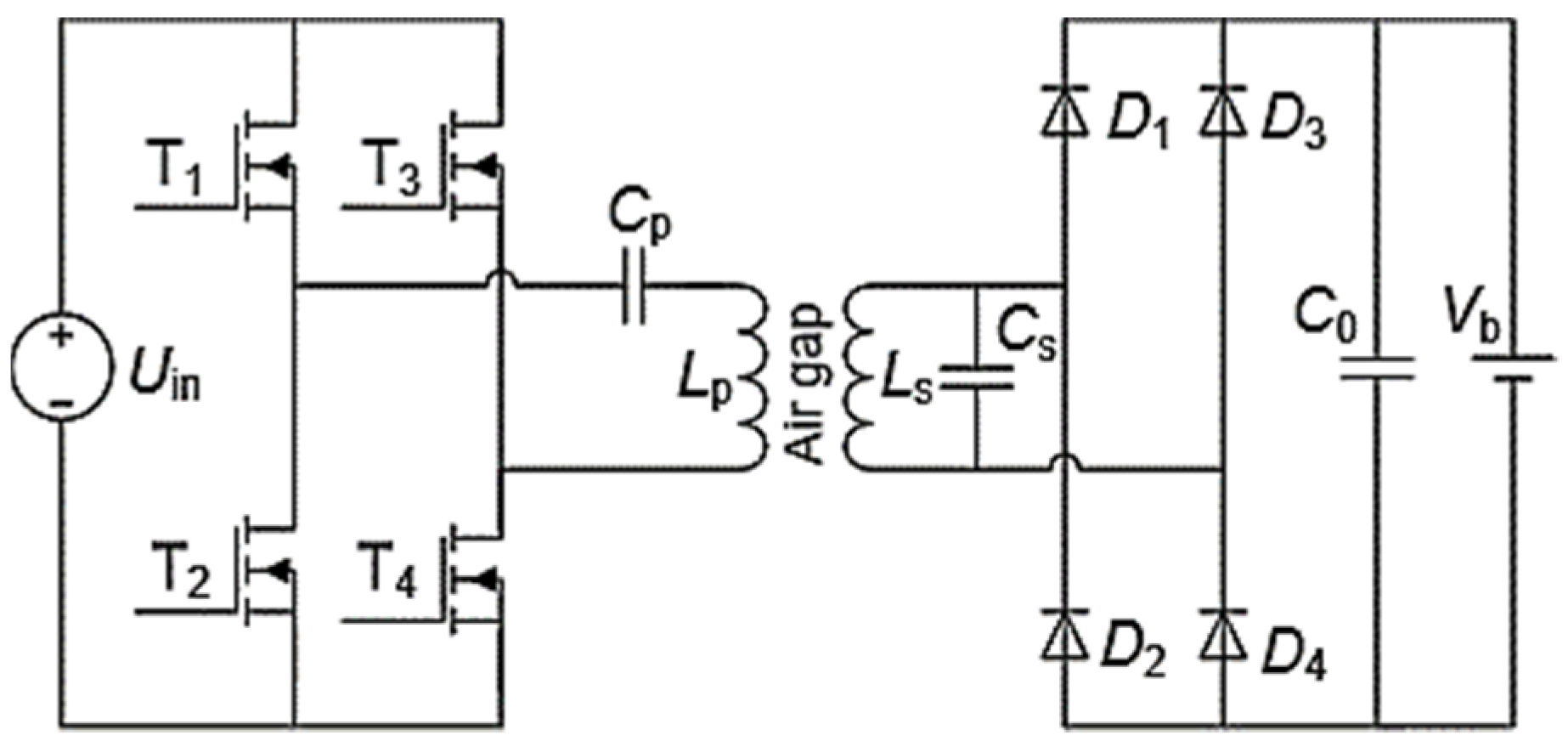
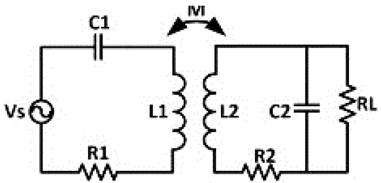
Figure 1 shows a typical wireless power transfer circuit. The diagram displays a voltage source feeding a full-bridge inverter used to convert the DC voltage into an AC high-frequency square wave. This inverter is conditioned to operate at the resonant frequency of the system. The secondary side contains a rectifier that will convert the high-frequency AC voltage into DC voltage, which is used to charge up the load. However, the series-parallel topology in this diagram illustrates the type of compensation used, as shown in
Figure 2. The series-parallel compensation enables filtering and enhances the waveform’s shape when entering the primary coil.
Figure 2 is used to obtain the relations illustrated in Equations (1)–(4). These equations are used for the series-parallel configuration system. Several equations govern the operation of the above circuit. These include the following:
The resonant frequency can be determined using Equation (5). The inductor and capacitor values for the coils can be adjusted to achieve the mathematical expression of the frequency.
- 2.
Angular frequency
The angular frequency in a resonant LC circuit can be calculated from Equation (3).
- 3.
Quality factor
The quality factor dictates the relationship between the amount of power stored (Apparent power) within the circuit to the amount of power dissipated (losses) during each cycle of operation.
- 4.
Coupling coefficient
The resonant circuit coils are coupled to transfer mutual flux. Although the coils are coupled, there could be some leakage flux. The coupling coefficient controls the level of coupling. Equation (4) dictates the relationship between the inductances with the coils. In tight coupling, the coefficient is 1, and, with tesla coils, it is about 0.2.
- 5.
Mutual inductance
Equation (4) shows the formula for calculating the mutual inductance. This refers to the current flowing in the primary coil, which induces a voltage in a secondary coil.
- 6.
Efficiency
The ratio of the power gain is expressed in Equation (7). The ratio of the power transferred through the secondary coils to the power feed to the primary coil dictates how well the system operates. The sum of the impedance of the components at the transmitter and receiver side is expressed by Equations (1) and (2) [
21].
The total impedance should be as small as possible to achieve the maximum current on the transmitter side. This can be achieved by setting the circuit in resonance. This will eventually remove the circuit’s reactive components, leaving only the resistive components. The resonant frequencies of the transmitter and receiver can be analyzed using Equation (3) [
21].
The mutual inductance of the coil’s setup can be calculated using Equation (4), which shows how the coupling coefficient (
K) relates to the inductances of the coils. The coupling coefficient should be large to achieve high efficiency, therefore the coils must be perfectly aligned [
7].
The coupling coefficient of standard WPT systems is between 0 and 1, with 1 being perfect coupling. Therefore, the coupling coefficient value is achieved from testing the coil design on ANSYS Maxwell. The resonant frequency can be calculated using Equation (5). At this frequency, the reactance of the inductor is equal to the capacitive reactance [
4].
The frequency is inversely proportional to the inductance and capacitance values. The quality factor can be derived from the resonant frequency to analyze the circuit parameters and determine the operational status of the circuit. Equation (6) provides the formula for calculating the quality factor using the inductance, resistance, and frequency values [
4].
The performance of this WEVC system is heavily based on the parameters used in designing the system. The operating frequency, coupling coefficient, and mutual inductance are crucial in establishing a working system. The power transfer ability of the system will be measured using the power efficiency formula in Equation (7). The power output and power input are related via power efficiency [
4].
Equations (1)–(7) govern the main circuit design used in this paper. The topology used in this circuit is the series-parallel configuration (
Figure 2), which has favorable current source characteristics towards the load compared to voltage source characteristics of the secondary series compensation configuration.
3. WEVC System Design and Analysis
The 3D modeling of the WEVC system is designed using ANSYS Maxwell software. The coil geometry is one of the central points of the WEVC system due to its various efficiency ratings. The space between the coils is set at 100 mm, a realistic spacing for a standard sedan vehicle in the United States [
22]. The efficiency of the wireless power transfer system is heavily based on the alignment of the coils [
12]. Therefore, in this paper, the coils were kept perfectly aligned with each other. Two rods are attached to the transmitting and receiving coils to excite the system with the current. The rods are 1 mm thick and have a length of 600 mm. An air region of 800 mm is created to encompass the design.
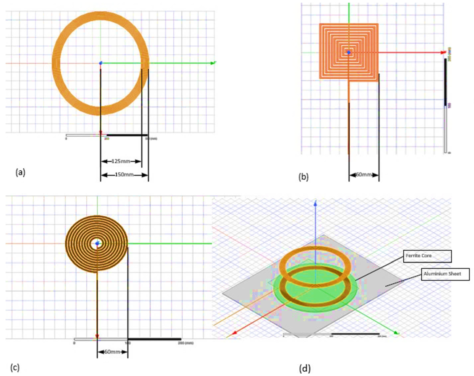
Figure 3 shows the three complete setups, including transmitting and receiving coils in ANSYS Maxwell. The coils are created using copper material, as copper can be used as a robust conductive material for the current. The different coils were used to analyze how the coupling coefficient, efficiency, and magnetic field radiation change with respect to design. The design parameters of each coil are shown in
Table 1. The analysis criteria for each design are presented in
Table 2.
Table 1 provides the values used to simulate the equivalent circuit from
Figure 2. ANSYS Simplorer simulations are used to study the operation of the WEVC system.
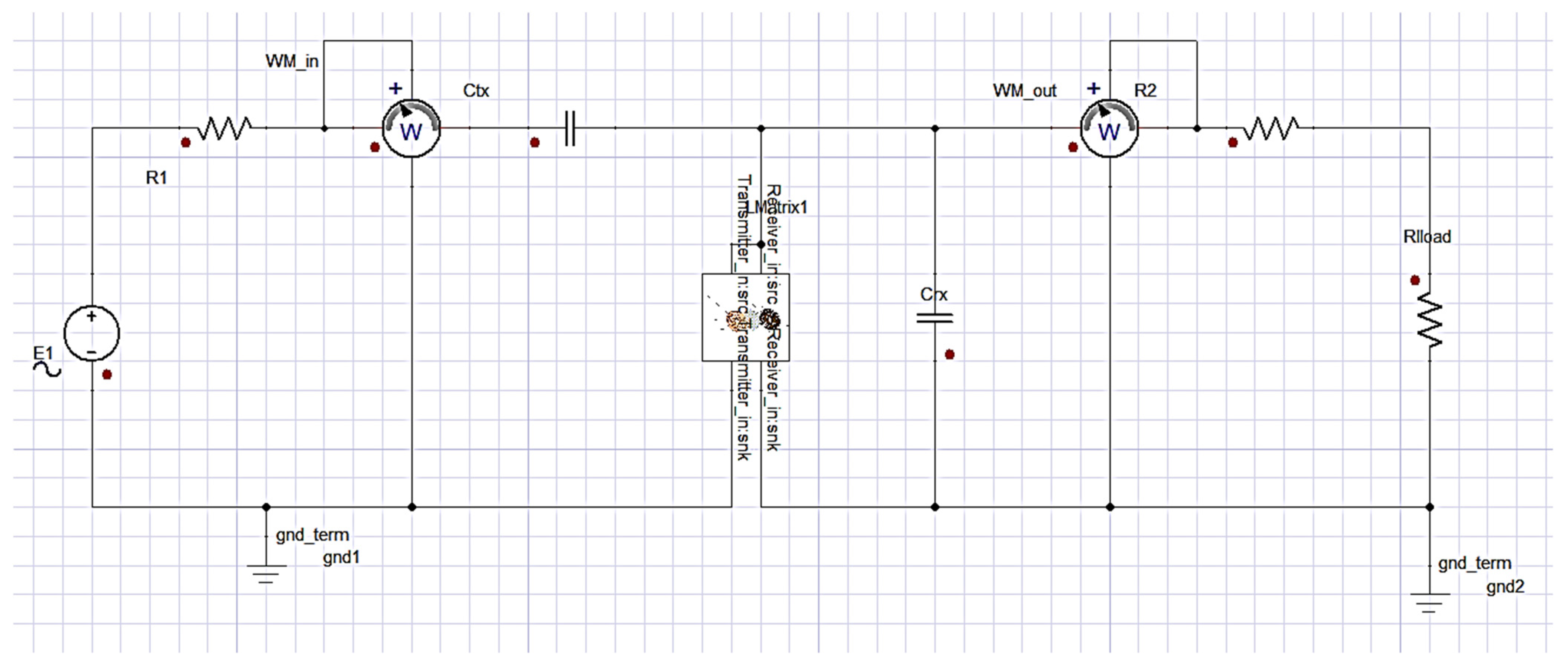
The Simplorer circuit shown in
Figure 4 was used to simulate the functionality of each coil geometry using an input voltage of 120 V AC.
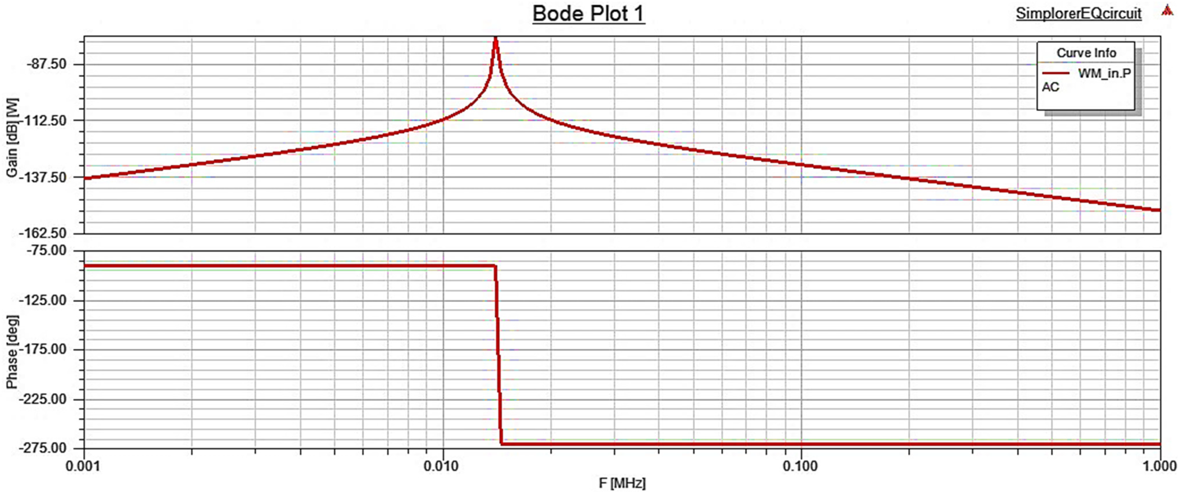
To verify proper functionality, the Bode plot for one of the coil geometries’, namely the 600 mm spiral coil, is analyzed and is shown in
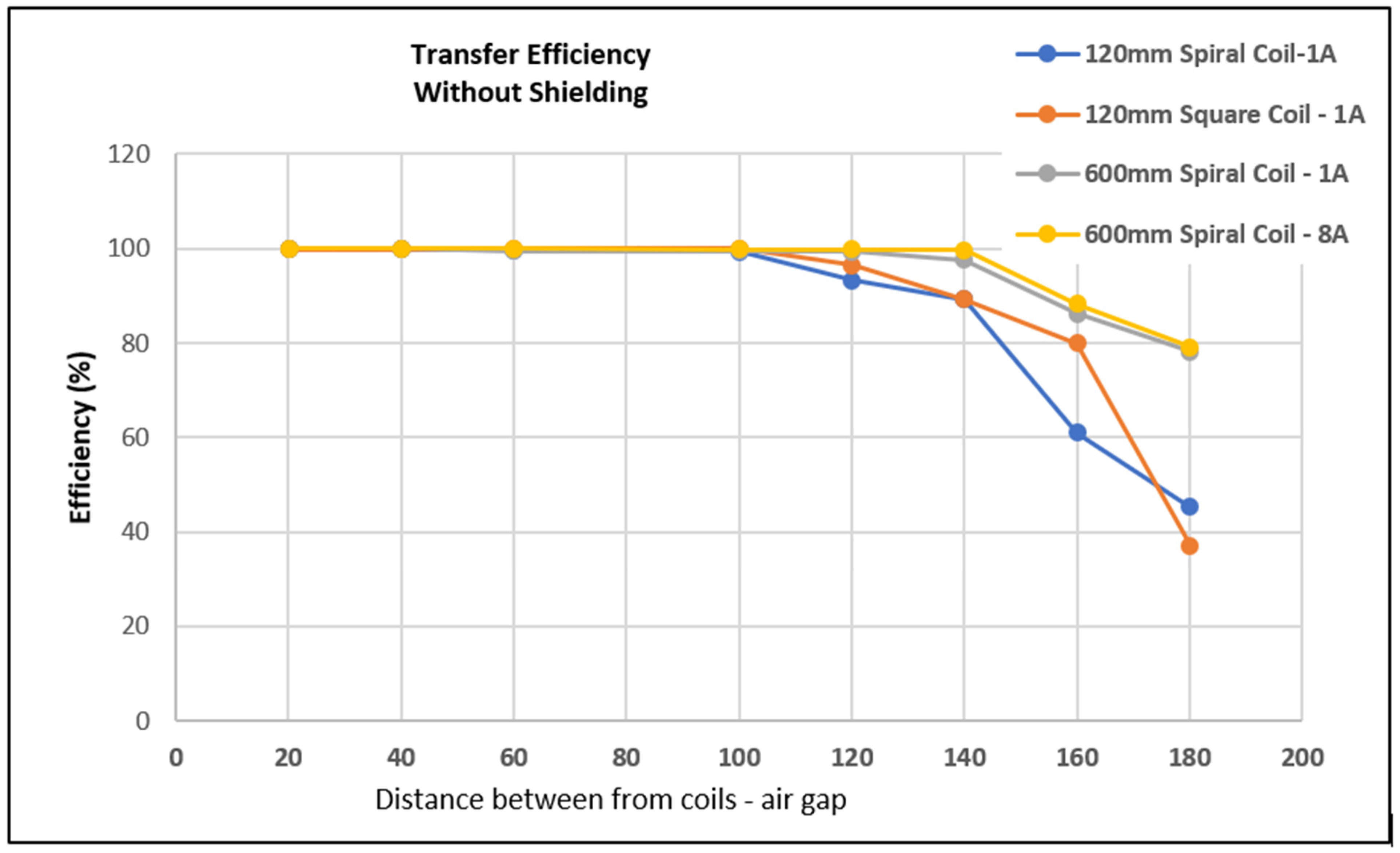
Figure 5. The Bode plot of the circuit using the 600 mm spiral coil shows the system’s frequency response. The plots show that the efficiency in dB is highest at the resonant frequency 88 kHz. At this frequency, the magnetic field generated by the transmitting coil is strongly coupled with the receiver coil. The coupling coefficient, mutual inductance, and efficiency of the three coil designs were analyzed. The efficiency of the three systems with varying air gap distances are shown in
Figure 6.
Figure 6 and
Figure 7 illustrate that the highest point of power transmission exists at one frequency point, with the efficiency dropping drastically across other frequencies. The 120 mm spiral coil exhibited the highest power transmission efficiency at 0.41 MHz, and the 120 mm square coil showed the highest power transmission efficiency at 0.35 MHz. The 600 mm spiral coil exhibited the highest power transmission at 88 kHz. The high efficiency at these frequencies supports the resonance frequency theory. The circuit operates at resonance at the above-stated frequencies, enabling high power transmission efficiency.
For the air gap of 100 mm, the efficiency percentage value for the 120 mm spiral coil is 96.3%, the 120 mm square coil is 98.3%, and the 600 mm spiral coil 97.5%. Many variables can explain this. One is the geometrical characteristics of each coil. In coil operation, the magnetic fields are generated across the coil turns and are superposed at the center of the coil. The square-shaped coil has turns covering the entire square area leading up to the center of the coil, thereby enabling a stronger field for transmission. Therefore, the 120 mm square coil provides the highest efficiency under the same parameters compared to the 120 mm and 600 mm spiral coils. These efficiency values are based on the circuit analysis of the equivalent circuit shown in
Figure 4, and these values could slightly change when other components such as power converters are added.
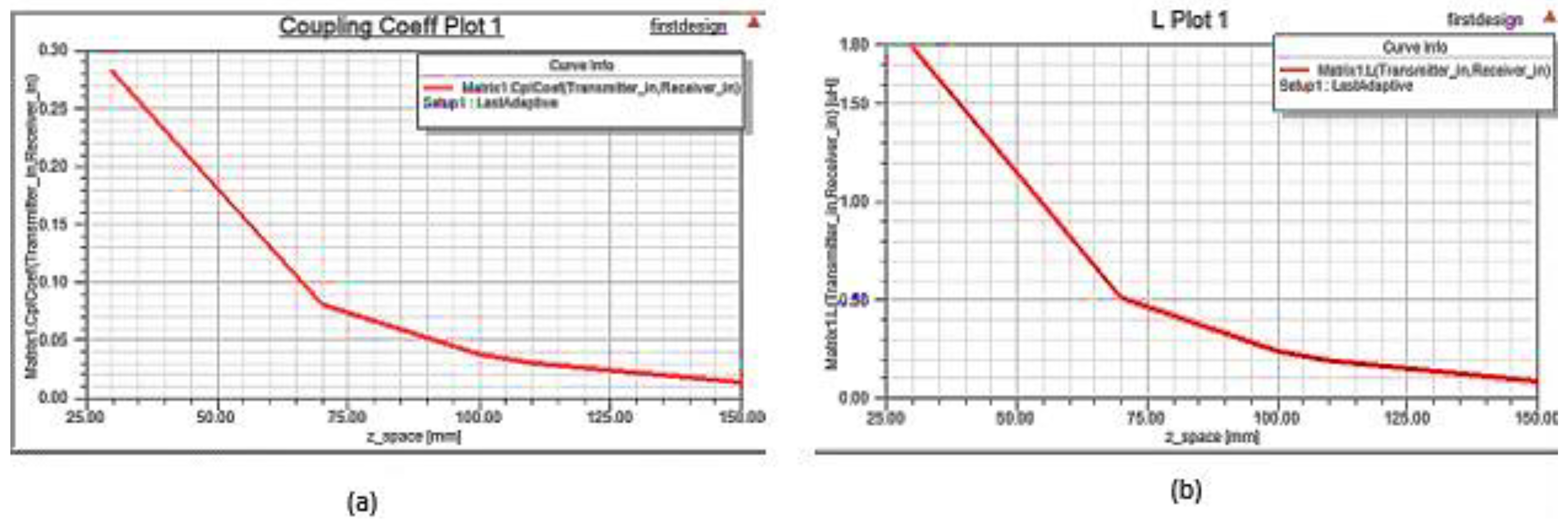
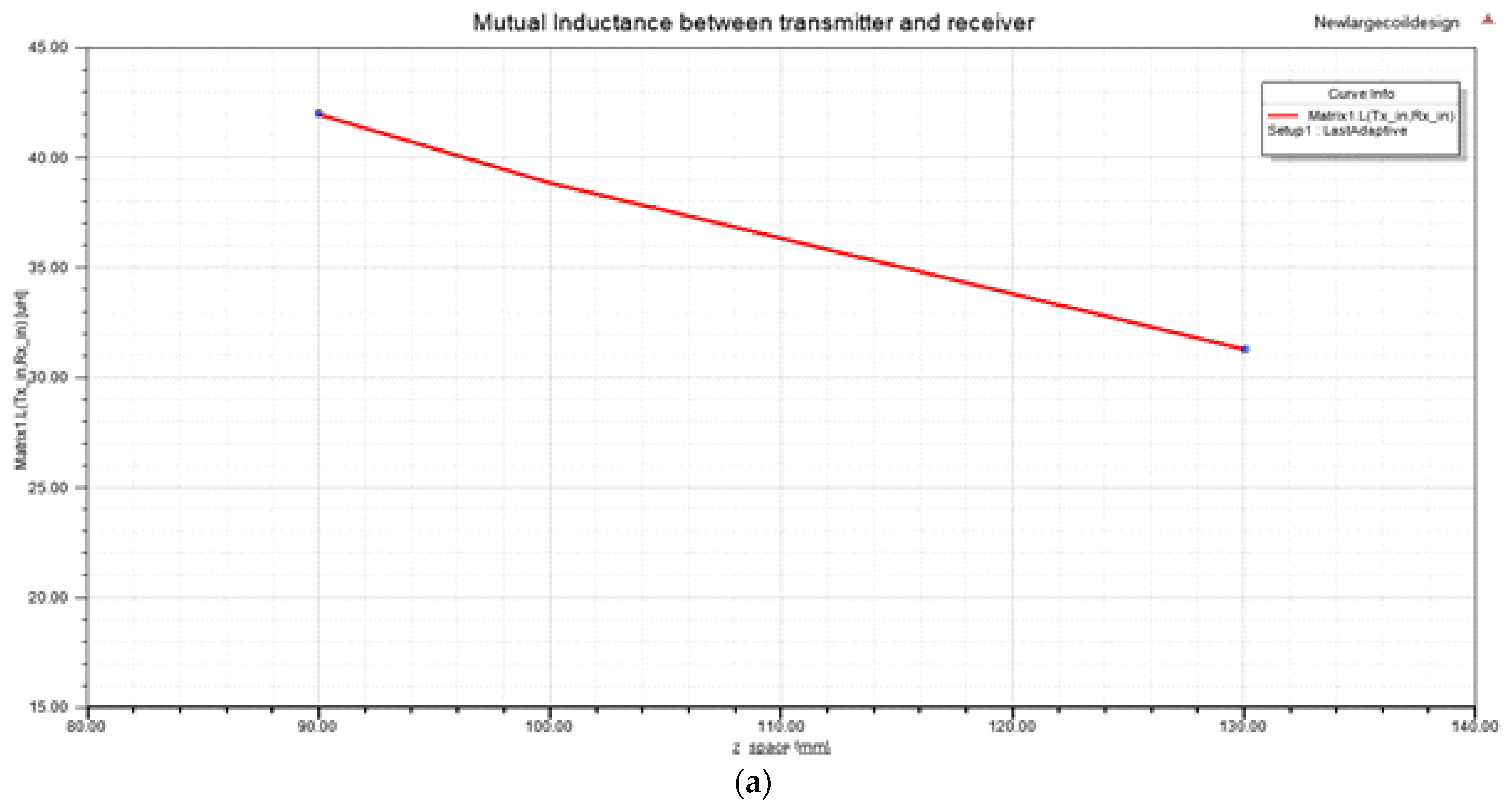
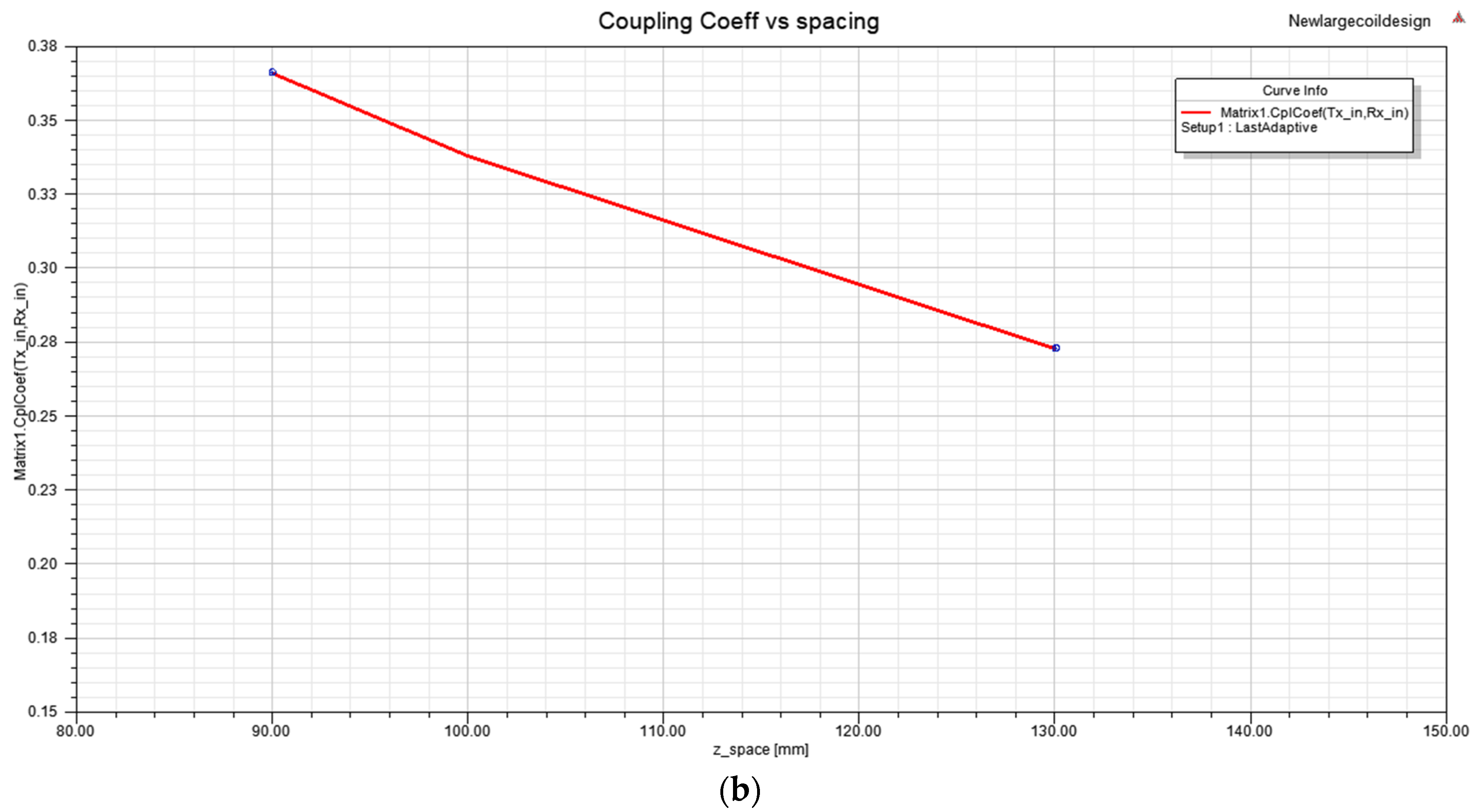
The coupling coefficient and mutual inductance values are directly related to the air gap spacing for all coil designs. The coupling coefficient and mutual inductance of each coil exhibits the same characteristics. These values decrease as the air gap between the coils increases. This paper shows the coupling coefficient and mutual inductance results for the 120 mm spiral coil, 120 mm square coil, and 600 mm spiral coil.
Figure 7,
Figure 8,
Figure 9 and
Figure 10 present the results of the equivalent circuit illustrating the behavior of the coupling 230 coefficient and mutual inductance. The 120 mm spiral coil and square coil show lower values of mutual inductance compared to the 600 mm spiral coil. This can be explained due to the current flowing through the coils’ geometry and how it induces a magnetic field across the coils. However,
Table 3 presents the results of each coil design for those values derived under the same circumstances and parameters using the Simplorer circuit in
Figure 4.
Efficiency is highest at the resonant frequency of 88 kHz. The coupling coefficient and mutual inductance values are higher in the 600 mm spiral coil compared to the 120 mm coils. The high values suggest an increase in power efficiency than in the 120 mm spiral coils, which can be seen in
Figure 6. Efficiency increases as the exciting current increases to 8 A. The coupling coefficient and mutual inductance are also higher when the coils are excited with 1 A. The increased coupling coefficient and mutual inductance values translate to a high-power efficiency even with increased air gap distances. Due to the higher power efficiency in the 600 mm, the spiral coil is excited at 1 A, and the 600 mm spiral coil is excited with 8 A to analyze the worst-case scenario for the electromagnetic safety study. An increased current excitation will lead to increased magnetic field induction, leading to higher magnetic flux leakage. The current is increased drastically, since improved charging time will likely involve feeding higher amperes to the transmitting coil to achieve a better power supply. The coupling coefficient across the coils are relatively similar. The mutual inductance changed drastically when the size of the coil was changed. Increasing the physical dimension of the coils leads to an increase in mutual inductance. Efficiency is highest in the square coil design. In coil operation, the magnetic fields are generated across the coil turns and are superposed at the center of the coil. The square-shaped coil has turned that cover the entire area of the square leading up to the center of the coil, thereby enabling a stronger field for transmission. The resonant frequency varies among the coil designs due to varying inductance values.
4. Electromagnetic Study
Due to the high magnetic fields emitted into the environment and potential heat hazards during charging, it is necessary to analyze the effects of these magnetic fields on the human body to see the possible severity of radiation effects. As stated in
Section 1, ICNIRP postulates the limits for electromagnetic radiation on humans. It is necessary to point out that the results obtained in this study are based on specific coil prototypes. The overall exposure limits will also depend on the geometry of the coils. The maximum human field exposure must exceed 27.3 µT according to IEEE 2010 [
11], and human body parts’ average magnetic field strength must not exceed 6.25 µT according to IEEE 1998 [
10]. 3-D FEA ANSYS Maxwell Software was used to analyze the eddy currents and magneto-static effects across several distances from the coils.
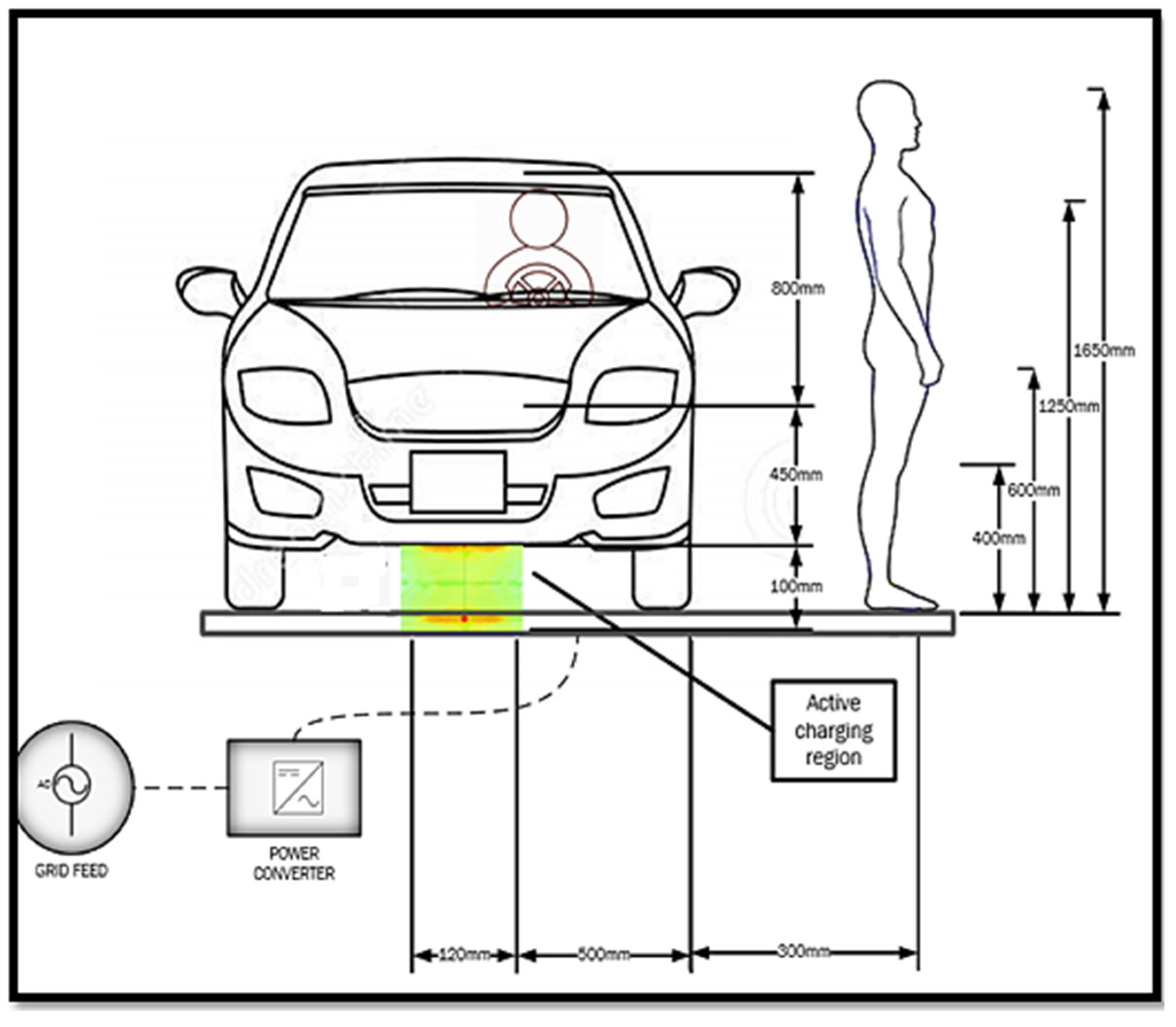
Figure 11 shows the dimensioning used to determine the radiation effects on humans and animals while the EV is being charged. A radial migration experiment was conducted in various X, Y, and Z directions. The highest magnetic flux density values are retrieved per radial distance. The magnetic flux density values are achieved using a magneto-static solution type on ANSYS.
Figure 12 shows an example of the measurements at two different locations of the charging coil for the 120 mm diameter spiral coil.
The magnetic flux density values are depicted in
Figure 13. By exciting the coil with a current of 1 A, the magnetic flux values were derived using the magneto-static solution type in ANSYS. For the 120 mm spiral coil, the magnetic field is below the ICNIRP threshold at about a 350 mm radius away from the edge of the coils; for the 120 mm square coil, the field is below the threshold at 300 mm, and, for the 600 mm spiral coil, the field is below the threshold at 450 mm. The coils are firstly excited with a current of 1 A. The 600 mm coil was excited with a current of 8 A to analyze the effects of a higher current on the system. The 600 mm spiral coil was chosen because it produced the highest magnetic flux values. Exciting the coil with a high current of 8 A accounts for the worst-case scenario.
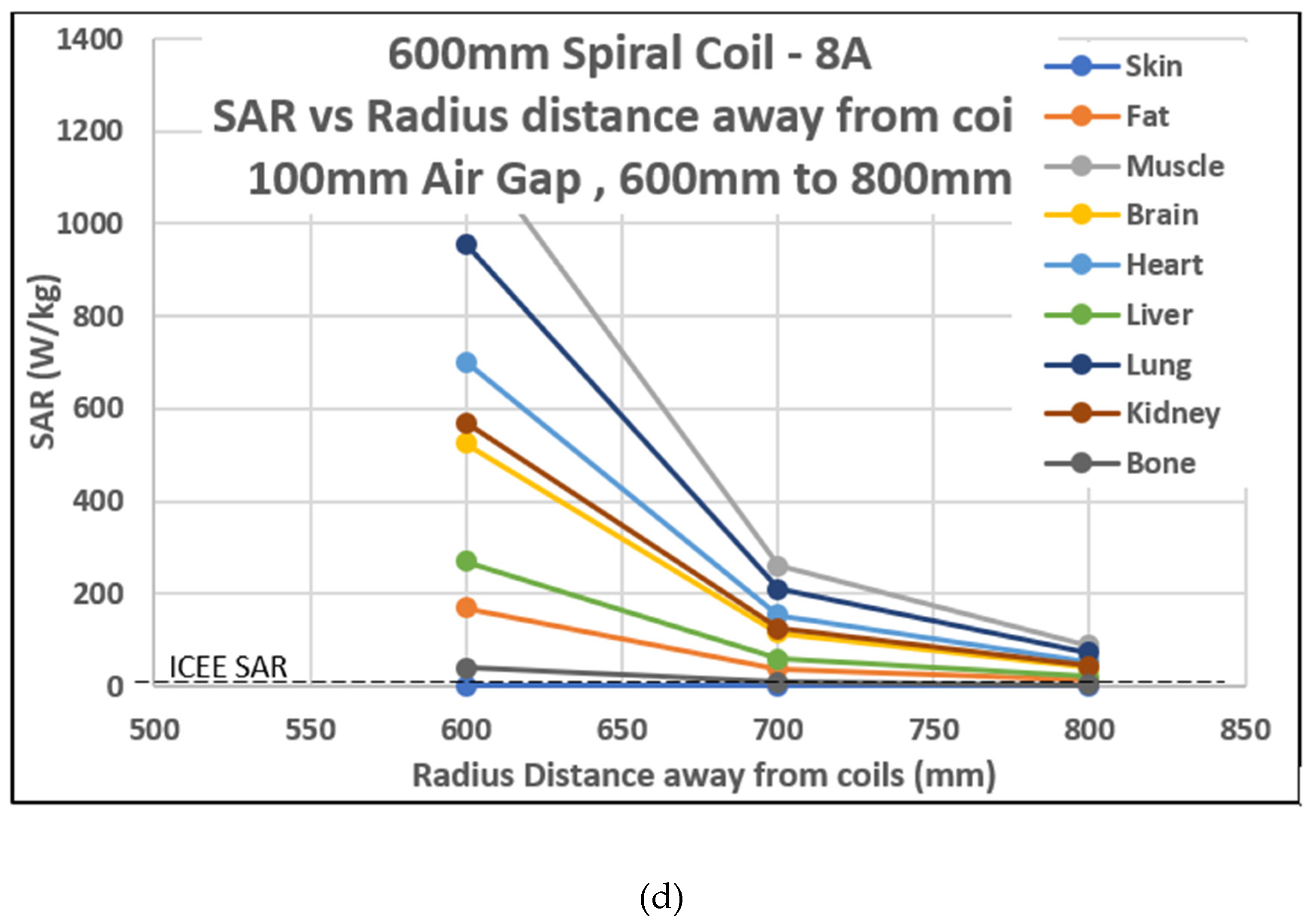
Figure 12d shows the significant increase in power and magnetic field exposure rates. For the 120 mm spiral coil excited at 1 A, the magnetic flux density values drop below the IEEE limit at 350 mm from the edge of the coils. For the 120 mm square coil excited at 1 A, the values drop below the limit of 300 mm from the edge of the coils. For the 600 mm spiral coil excited at 1 A, the values drop below the limit 450 mm away from the edge of the coils. For the 600 mm spiral coil at 8 A excitation, the values drop below the IEEE 2010 limit of 27 µT at 300 mm and below the IEEE 1998 limit of 6.25 µT at a further distance of 600 mm. This is explained by the increase in current excitation leading to higher magnetic flux values.
The magnetic flux values changed with respect to the varying air gap, displaying increased magnetic flux leakage with the increased air gap. Many techniques have been applied to WEVC systems responsible for reducing the amount of magnetic flux leakage from the system. Metallic plates and ferrite structures have been used to mitigate the magnetic flux radiation produced by WEVC systems [
13,
17]. Ferromagnetic material has high relative permeability which can be used to enclose magnetic flux. Chosen Ferrite core has a residual induction value of 0.2 T and a relative magnetic permeability higher than 800. While only using an aluminum sheet, the magnetic flux values increased. This results from the eddy currents being induced in the shielding sheet. Adding ferrite material will cause this eddy current to create a new magnetic field, which acts against the first created field, thereby reducing the escaped flux. This WPT system in this paper employs an aluminum sheet and ferrite core base-shielding technique to mitigate the leakage of magnetic flux, thereby reducing the exposure rates of the WEVC system when the charging sequence is conducted. The aluminum sheet used for the 120 mm diameter coils is approximately 400 × 400 mm, with a thickness of 3 mm.
The ferrite core is a 250 mm diameter circular plate with a thickness of 2 mm. Most typical sedan vehicles have metallic parts that help mitigate leakage flux; however, the added plates help concentrate the shielding effects to the area with the highest magnetic field.
Figure 3d shows the geometry design for the coils, including the shielding components.
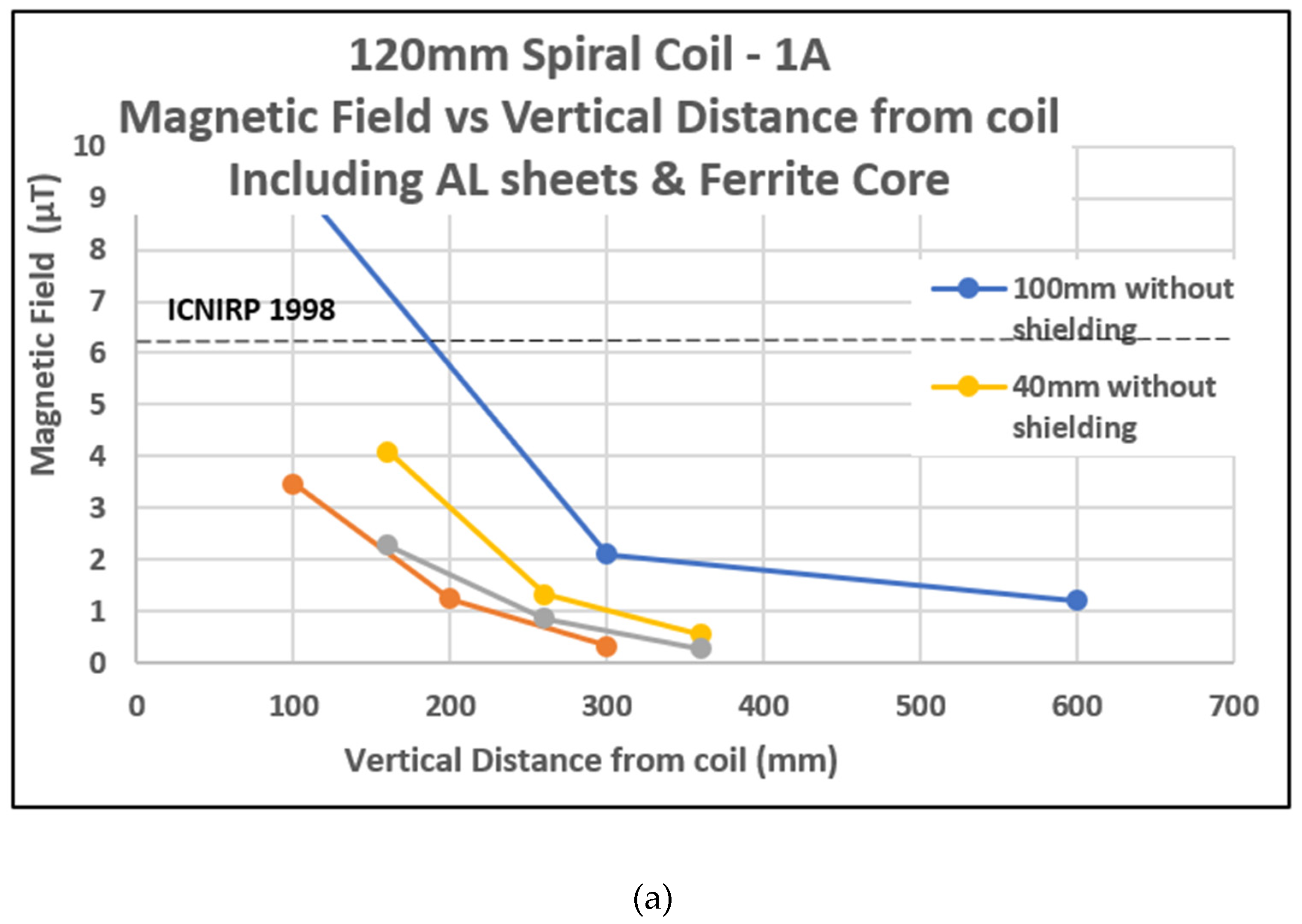
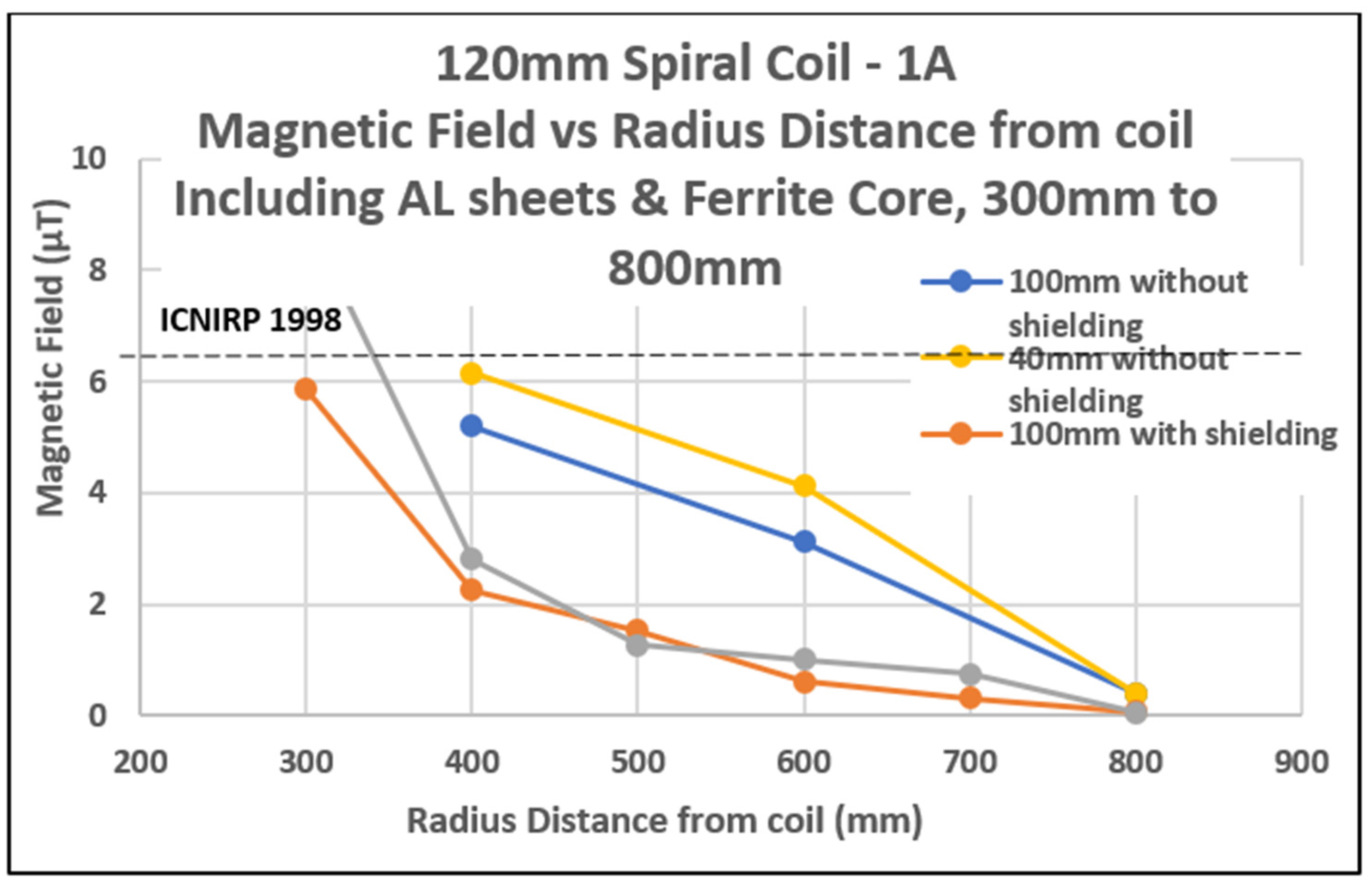
Figure 14 shows the decrease in magnetic field values and improves the safe distance by about 350 mm–400 mm. The coil geometries used to analyze the shielding are the 120 mm spiral coil and the 600 mm spiral coil because they account for the best-case and worst-case magnetic flux leakage values. The 120 mm spiral coil is excited by 1 A, and the 600 mm spiral coil is excited by 8 A. The shielding experiment is necessary to understand the effects of shielding techniques on the leakage; therefore, using these two coil geometries will suffice for this experiment.
This experiment section explicitly accounts for two air gap distances, i.e., 100 mm and 40 mm. As shown in
Figure 14, when the air gap is reduced from 100 mm to 40 mm, the magnetic flux density values drastically increase from 1.65 µT to 11.1 µT due to the increased power transmission. When running tests using a 120 mm spiral coil excited at 1 A, the magnetic flux values fall below the IEEE limits at about 400 mm away from the edge of the coils. The magnetic flux falls below the IEEE limits at about 700 mm away from the coils when the 600 mm spiral coil excited at 8 A is used.
The SAR can be calculated using the electric field emitted by the coil system. SAR levels are used to quantify the amount of radiation sustained by a specific part/tissue of the human body, thereby determining the safety parameters. SAR levels are quantified in watts per kilogram [
18].
The SAR levels were calculated using the formula in Equation (8). Conductivity of the chosen 328 material is represented by σ, the density of the material is represented by ρ, and the electric field by E. The values for tissue permittivity, conductivity, and density are obtained from the foundation of research on information technology (IT’IS) [
18].
Table 4 and
Table 5 show the tables used in acquiring the SAR level calculations.
Because magnetic fields penetrate the body tissues to different depths at different frequencies, the operating frequency of the coils was used to compile
Table 4 and
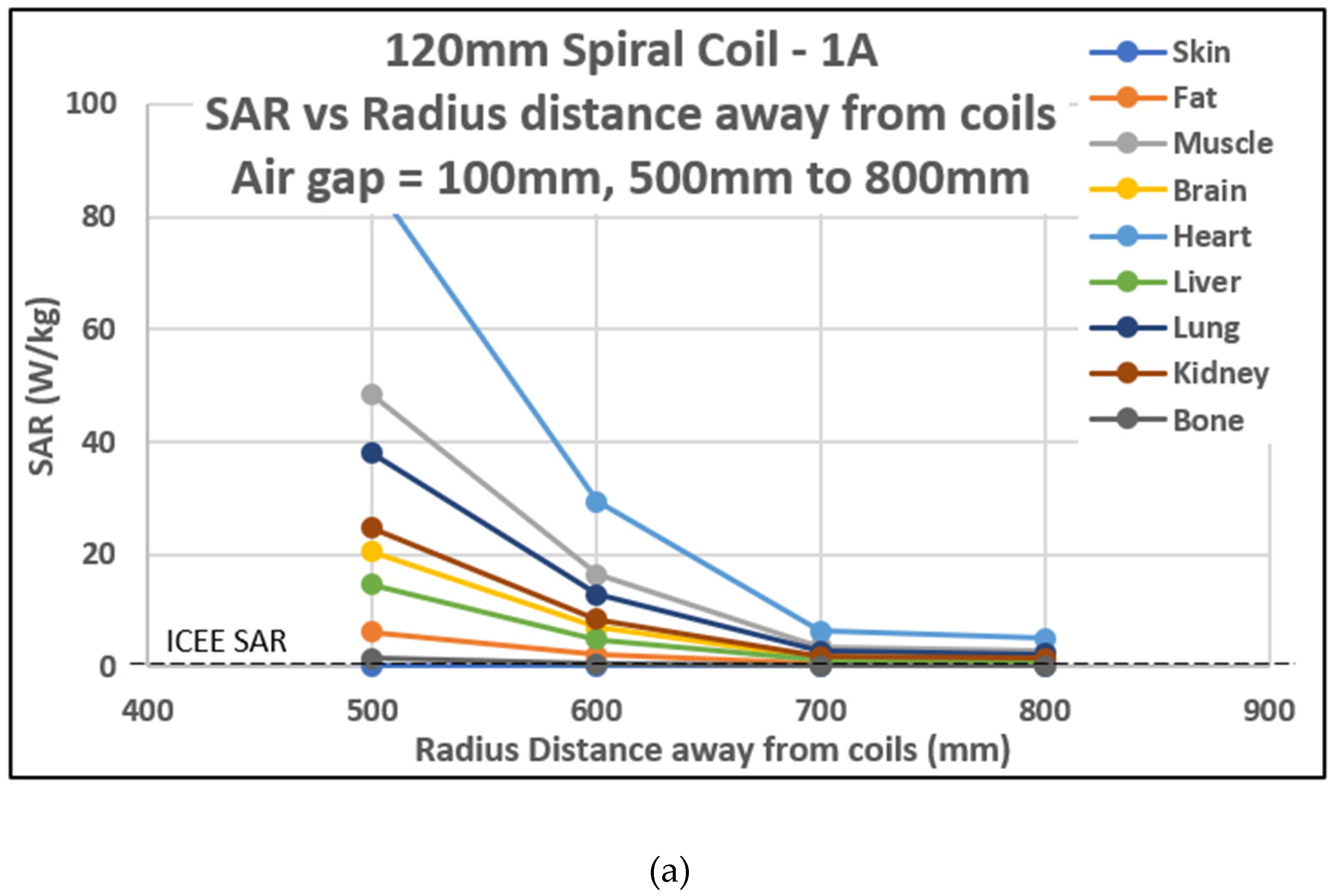
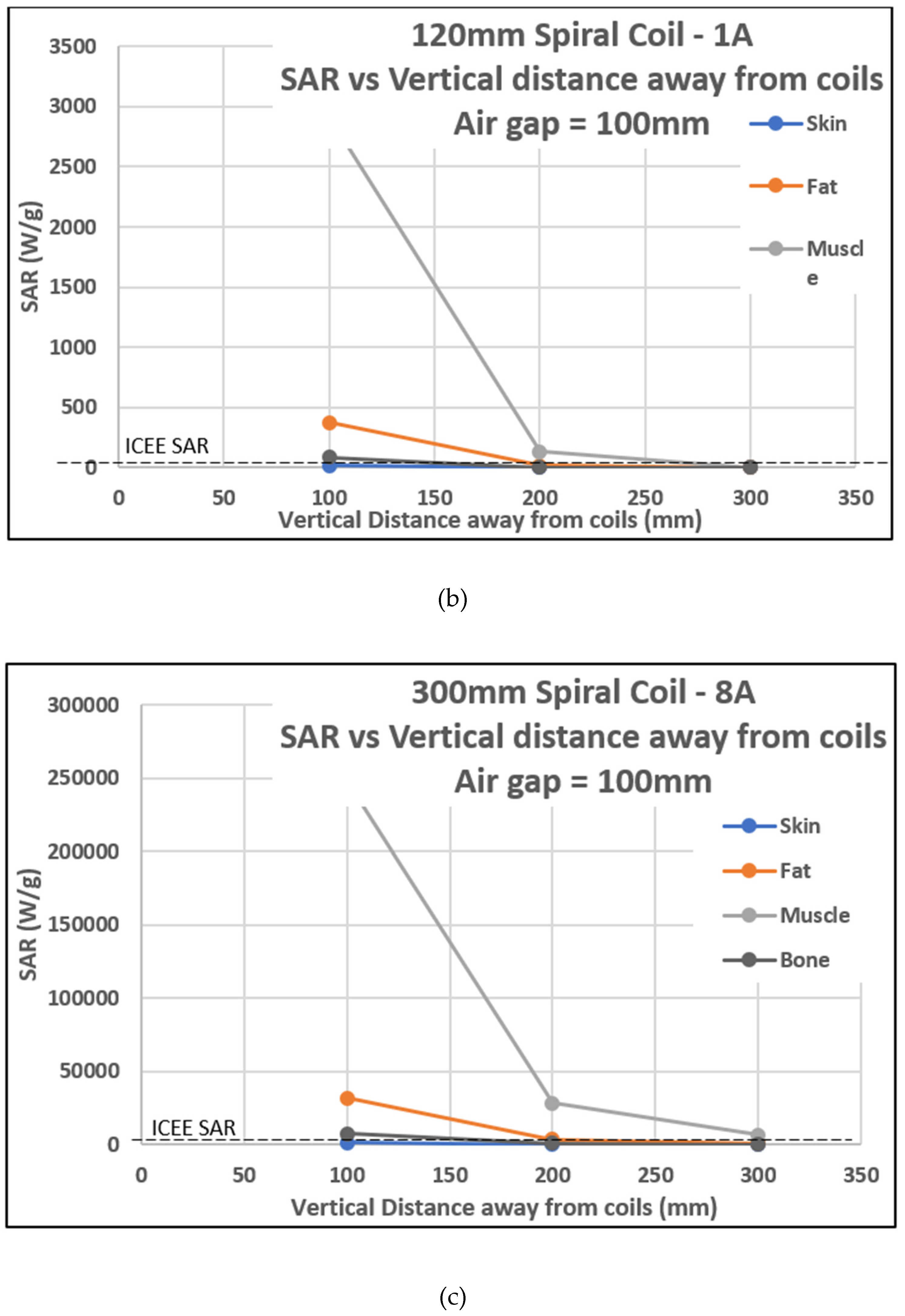
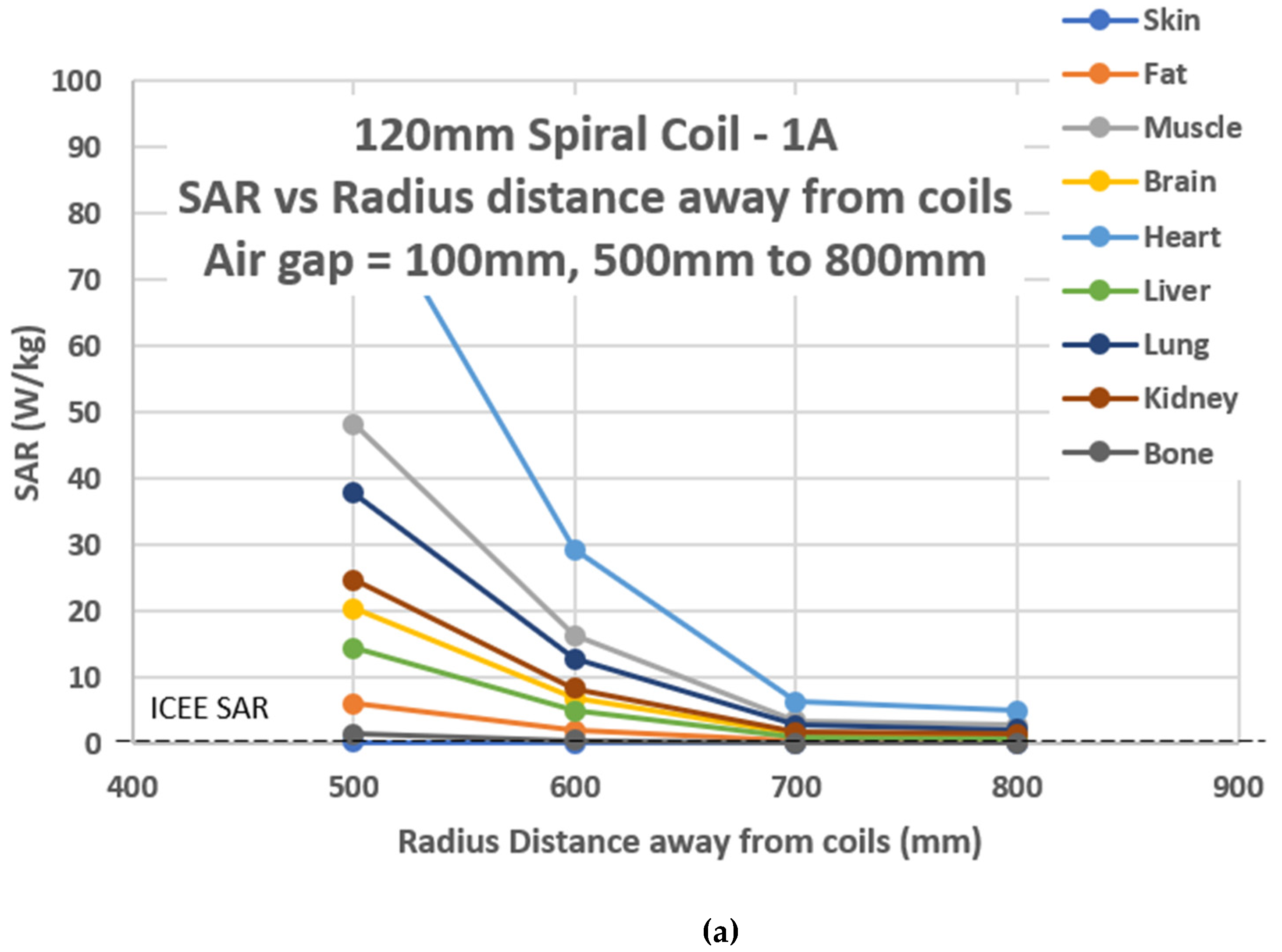
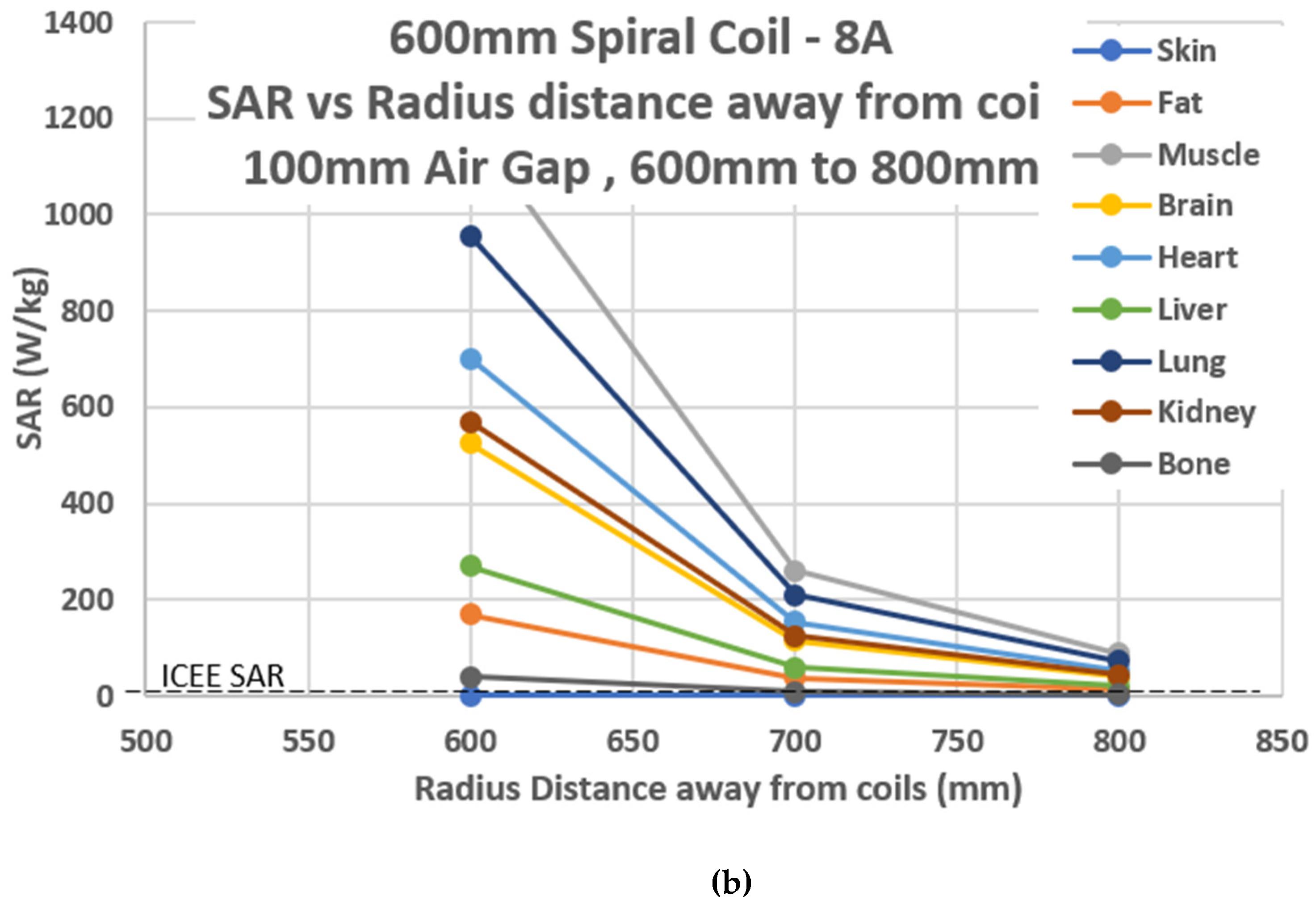
Table 5. The electric field is achieved and used to calculate the SAR levels by applying the eddy current solution type on ANSYS Maxwell. IEEE determines the SAR level limits at 4 W/kg for limbs and 2 W/Kg for the head and trunk. These values are used as a threshold for analyzing the SAR levels produced by the WEVC system in this paper and are shown in
Figure 15.
The 120 mm diameter coil is excited at 1 A, while the 600 mm diameter coil is excited at 8 A to analyze the differential range in SAR levels considering the geometry of the coil and the current passing through the coil. SAR calculations are based on the electric field values. The maximum magnetic field values did not thoroughly correlate with the maximum electric field values based on position [
23]; however, there is a similarity in progression changes over a long distance. The electric field values are increased with the distance from the coils that are decreasing.
For the 120 mm spiral coil, 120 mm square coil, and 600 mm spiral coil operating at 1 A excitation, the SAR levels are under the threshold at 700 mm away from the coils. For the 600 mm spiral coil excited at 8 A, the SAR levels fall under the threshold at 900 mm away from the coils. With shielding, the safe distance is improved by up to 350 mm. Considering the regulations of the ICNIRP IEEE, 600 mm is a safe distance away from the coils. Vertically, anywhere past 300 mm is safe for humans. Animals within 500 mm of the coil are at risk of high exposure levels, meaning there should be a complete prohibition of movement underneath the vehicle during the charging process. These safe distances enable geometry design engineers to find the best middle ground in WEVC system design.
This research work contributes to the blueprint that can be used to balance safety measures against performance specifications. This will enable safer system design for the public while enhancing product approval by the governing bodies [
24].
5. Conclusions
Due to the pollution crisis faced by the modern world, electric vehicles have surfaced to mitigate the pollution levels produced by gasoline combustion engines. Plug-in charging techniques have certain drawbacks, including a lack of mobility support and safety hazards in faulty wiring. Therefore, WPT is a potential solution and upgrade to the current plug-in technique. The different ways of conducting WPT are discussed, and the main efficient technique is chosen and applied in this research. There are many different techniques of WPT. The most efficient technique is magnetic resonance. In magnetic resonance, the WPT system operates at a frequency that enables high resonance between the transmitting and receiving coils, thereby enabling higher power transmission and efficiency. The main theory and equations that govern the operation of a typical WPT system are discussed.
The various compensation techniques used in enhancing voltage flow and stability are analyzed with the series–series and series–parallel techniques mostly used for the circuits designed in this work. The series–parallel provides advantages in low component count requirements and better efficiency contribution compared to the parallel-based compensation techniques. The electromagnetic study was carried out for the designed WEVC system. Three coil designs, namely, the 120 mm diameter spiral coil, 120 mm diameter square coil, and the 600 mm diameter spiral coil, were the different coil geometries used in this research work.
The coupling coefficient and mutual inductance behavior for all coil designs were analyzed. Keeping the air gap distance at 100 mm, the coupling coefficient is highest when using the 120 mm square coil, while the mutual inductance was highest for the 600 mm spiral coil. The magnetic flux density values are determined at various radial distances away from the coils while the charging process is conducted. All three coil geometries are excited by the 1 A current. The 600 mm spiral coil showed high levels of magnetic flux leakage compared to the rest of the designs; therefore, coil geometry was excited by 8 A to show a worst-case scenario that would indicate a high amount of magnetic flux leakage. Eddy current analyses were conducted, and electric field values were determined at various radial distances away from the coils. Of these values, 386 were used to calculate the SAR levels. The magnetic flux density was compared to the IEEE standards of less than 6.25 µT and less than 27 µT. The SAR levels were compared with IEEE limits at 4 W/kg for limbs and 2 W/Kg for the head and trunk. The highest amount of magnetic flux was 523 µT between the coils, which greatly exceeds ICNIRP 2010′s value of 27 µT and ICNIRP 1998′s value of 6.27 µT. Therefore, pets or humans would be unsafe anywhere within 100 mm of the charging coils. This is true for the 120 mm spiral coil, the 120 mm square coils, and the 600 mm spiral coil with 1 A current excitation.
At the air gap of 100 mm, the magnetic flux density falls lower than ICNIRP 1998′s threshold of 6.27 µT at a radial distance of 400 mm away from the coils. Therefore, a safe distance is about 500 mm away from the coils. Shielding techniques were applied to the coil design to mitigate leakage flux and improve efficiency. Aluminum sheets and ferrite core materials were used on the coil geometries to analyze shielding effects. With shielding, the safe distance improved by more than 200 mm. For the 120 mm spiral coil, the 120 mm square coil, and the 600 mm spiral coil operating at 1 A excitation, the SAR levels are under the threshold at 700 mm away from the coils.
For the 600 mm spiral coil excited at 8 A, the SAR levels fall under the threshold at 900 mm away from the coils. With shielding, the safe distance is improved by up to 350 mm. The proposed eco-friendliest system will have optimized power efficiency while maintaining low levels of exposure. This research work contributes to the blueprint design engineers can use to balance performance specifications (efficiency) against safety requirements.
6. Future Work
Multiple scholarly ideas can be implemented in WEVC systems to reduce magnetic flux leakage. Some of these could be using reactive conducting coils to create reverse EMI to counter leakage flux, analyzing the effects of other materials on radiation mitigation and how materials affect the system’s resonant frequency, and the results of radiation on the implants of human and pet bodies. For optimum productivity and efficiency, the EV must be perfectly aligned with the transmitting coil on the ground. Misalignment problems could lead to a huge drop in transmission efficiency; therefore, research should be conducted to improve the misalignment drawback. Sensors could be used to ensure perfect alignment for charging processes. Exposure occurs because of direct coupling and indirect couplings such as EMF coupling to worn medical devices or implants. Sparks or discharges can occur from field exposure. Stray currents and voltages could induce nearby metal structures, causing heating effects. These heating effects could lead to burns on the human skin from touching said structures. The heating of metal structures and debris could obstruct WPT during the charging process. Research on detection devices for debris prevention mechanisms would enhance the WEVC operational system.
