1. Introduction
Figuring out the patterns of flame front propagation in premixed gaseous media is a crucial task both for practical matters and for ensuring the explosion safety of flammable media. In addition, the formation of hydrogen–air mixtures is possible in nuclear reactors during off-design and emergency operating conditions of the reactor.
The formation of ignition sources and the flame front propagation can be divided into a number of stages, each of which is characterized by its own patterns. For example, in the works [
1,
2], the formation of an ignition source during spark discharge at an early stage was considered. The relationship between concentration flammability limits and initial pressure, laminar combustion rates, and ignition energy near concentration limits can be found in [
3].
The expanding combustion products set the unburned combustible mixture in motion. This flow, depending on the channel geometry, can subsequently determine the nature of the flame front propagation. The influence of the location of the initiation source relative to the channel walls and the closed/open ends of the channel was considered in [
4] for a mixture of syngas with air and for different hydrogen concentrations, as well as in [
5]. Also, the combustion of syngas–air mixtures in ducts was studied in [
6].
The influence of ignition position on the propagation of the flame front in hydrogen–air mixtures was studied in [
7,
8]. The influence of the geometry of the side walls on the propagation of the flame front in a half-open channel was numerically studied using the dissipation-free numerical technique (CABARET) and pseudo-spectral method in [
9]. Propagation of a flame front in a hydrogen–air mixture in a channel with contraction was numerically analyzed in [
10]. More developed combustion and the interaction of the flame front with obstacles were studied in [
11]. The processes of self-ignition in hydrogen–air mixtures upon reflection from a closed end were studied in [
12].
Among the key parameters that determine the propagation of the flame front at the initial stage of combustion is the development of various types of instabilities. The flame front can acquire a tulip and distorted tulip shape [
13]. Acoustic fluctuations and some coherent structures were obtained in [
14,
15]. A numerical analysis of acoustic perturbations was carried out in [
16]. A number of works are devoted to the study of thermoacoustic instability and acoustic waves in hydrogen–air and hydrogen–oxygen mixtures [
17,
18,
19].
The role of hydrodynamic instability is presented in [
20] for a disturbed flame front in a closed pipe and in [
21] when the flame front propagates in a flow between two parallel plates. The generalized effect of hydrodynamic and thermal diffusion instabilities is considered in [
22], and hydrodynamic and thermoacoustic instabilities are considered in [
23]. Fractal structure developing due to hydrodynamic instability was numerically studied in [
24]. Minaev [
25] showed that hydrodynamic instability can be affected by Kelvin–Helmholtz instability. At the same time, coherent structures in the flow and the development of Kelvin–Helmholtz instability were investigated in [
26].
Currently, a significant number of studies are being conducted on flame front propagation in lean mixtures. In contrast to deflagration propagating in near-stoichiometric mixtures, in lean and ultra-lean hydrogen mixtures, the structure of the flame front can be a system of disturbances or multiple discrete combustion sources, the dynamics of which significantly depend on the initial concentration of hydrogen in the mixture. In different works, they were called cups, caps, small balls of flame, and vortex rings [
27,
28].
Flame acceleration can be a big threat to industrial facilities containing hydrogen due to its low ignition energy and wide flammability limits [
29]. Porous materials in the channel are an effective method of flame quenching due to the high surface-to-volume area of the materials. Among these materials, polyurethane foam, steel wool, and porous metals, like copper, are the most prominent. The ability to quench flame propagation depended on the pore size of the material [
30] and the thickness of the obstacle [
31]. On the other hand, porous material can also lead to the turbulization of the unburned mixture and increase the burning area, which in turn leads to flame acceleration [
32]. Thus, it is important to determine the parameters of the porous materials that can quench flame propagation.
When a source of ignition is located on the side surface of a channel, the combustion products expand. In the case when the propagation of the flame front is determined by the expanding combustion products, the influence of hydrodynamic instability is one of the determining ones. The development of hydrodynamic instability is influenced by various factors, in particular, the geometry of the channel has a significant influence, including the structure of the coatings of the internal walls and their shape. As was shown in [
33], the presence of porous coatings can affect the flow of the unburned mixture and thereby influence the development of disturbances at the flame front.
The purpose of this work was to determine the velocity of the flame front during ignition in a channel with porous coatings and determine the size of flame disturbances.
2. Experimental Setup
The experimental setup is shown in
Figure 1. The main setup element is a rectangular channel, open at one end, with transparent glass windows for Schlieren visualization of the flame front. Windows were made of optical quartz glass. The length of the rectangular channel was 200 mm, the height of the channel was 40 mm, and the distance between the glass windows was 20 mm. Polyurethane porous coatings or steel wool were used, the thickness of which was 10 mm. When placing porous coatings or steel wool in the lower part of the channel, the size of the free passage of the channel was 20 × 30 mm. The movement of the flame front in the visible part of the channel was registered.
The rectangular channel was filled with a mixture from a 3 L vessel; a CPU fan was placed inside the vessel. The combustible mixture was supplied from the closed end of a copper tube with a bore diameter of 4 mm. The section was repeatedly filled by an air displacement method for 10 s. The volume of the supplied mixture was 8–10 times greater than the volume of the channel. The experiments were carried out with two molar excesses of hydrogen (equivalence ratio): ER = 0.4 and ER = 1.0.
One second after filling, the hydrogen–air mixture was ignited with a spark gap from the GI-1 pulse generator through a car coil. The initiation energy did not exceed 0.1 J. The experiments were carried out at initial atmospheric pressure. The initial temperature of the mixture was 300 K.
A Phantom VEO 710 high-speed camera was used as the recording equipment. The frame rate varied in the range of 3000–30,000 fps, and the exposure time was 2 μs. Schlieren visualization was carried out using a shadow device IAB-451. A Foucault knife installed in the focal plane was used. Each shot was repeated five times to ensure reproducibility.
Polyurethane foam with an amount of 10–80 pores per inch (ppi) was used. The pore size was 2.5 mm, 0.8 mm, 0.6 mm, and 0.3 mm for 10 ppi, 30 ppi, 45 ppi, and 80 ppi, respectively. Polyurethane foam was chosen as a material with a relatively low coefficient of thermal conductivity compared to metals. Photographs of the polyurethane foam are presented in [
34]. The foam was not damaged or burned after the experiments. A picture of the foam after 20 experiments can also be found in [
34].
The experimental results were compared with those obtained using steel wool with a fiber size of 30 µm. Steel wool was used for only one experiment, and it was changed before each experiment. Porosity was defined as the ratio of the empty volume to the total volume of the sample:
The porosity of the polyurethane used was ε = 95–99%. The porosity of steel wool was 99%. The porosity of polyurethane was determined by the displacement of water. The porosity of steel wool was determined through the weight and density of the steel and the dimensions of the sample. The pore density of polyurethane was determined statistically in several linear directions on the surface of the sample. The transverse size of polyurethane and steel wool fibers was determined with a micrometer. For polyurethane with a pore density of 10 ppi, the transverse size of the fibers was 200 μm; with a pore density of 80 ppi, the fiber size was 20 μm. The average transverse size of the steel fiber was 30 μm. Geometric characteristics of polyurethane and hydraulic resistance coefficients are presented in
Table 1. In the combustion mode presented in this work, polyurethane is chemically inert and elastic. Therefore, it can be used to attenuate explosions and detonations when the initial temperature is below the melting point. Compared to porous metals and ceramics, cost is also an advantage.
3. Results
Figure 2 shows Schlieren photographs of the flame front propagation in the empty 20×40 mm channel for a stoichiometric hydrogen–air mixture with
ER = 1 (
Figure 2a) and for a lean mixture with
ER = 0.4 (
Figure 2b). The Schlieren photographs show density gradients. The Foucault knife was placed vertically so that depending on the direction of propagation, the flame front appeared either as a light line or as a dark line. The directions considered and discussed in this work are marked in
Figure 2a. The red direction (I) corresponds to the direction toward the open end of the channel, the blue arrow (II) corresponds to the direction toward the bottom coated wall, and the green arrow (III) corresponds to the direction toward the closed end of the channel. Thus, the flame front propagating toward the open end (I) is represented as a light line; the flame front propagating toward the closed end (II) is represented as a dark line.
Firstly, it can be seen that the flame front extends toward the open end due to the expansion of combustion products and their outflow toward the open end. Secondly, disturbances are formed at the flame front. The flame front propagating downwards (III) is presented as a set of light and dark lines. However, in the absence of disturbances or their dissipation, visualizing the lower side of the flame front is quite difficult; for example, as shown in
Figure 2b for the lean mixture (
ER = 0.4) with time moments of 114,560 μs, 200,960 μs, and 285,360 μs.
The movement of the flame front to the bottom wall is more dynamic than further movement along the axis of the channel. Therefore, the sequence of photographs was divided into two blocks: the first three photographs have a small interval and the last three photographs have a different time interval. The field of view is partially blocked by sealing rubber inserts, which are located outside and do not affect the flow inside the chamber.
Figure 3 and
Figure 4 show the Schlieren photographs of the flame front in a channel with a porous coating for two mixture compositions: a mixture with
ER = 0.4 (
Figure 3) and
ER = 1.0 (
Figure 4). To compare the processes of the flow of combustion products, unburned mixtures, and the propagation of the flame front, instead of a porous coating, an impermeable 10 mm thick steel plate was used and was placed instead of a porous coating (
Figure 4f). As can be seen in
Figure 3c and
Figure 4e, the steel wool has residual deformation and elasticity, so it is difficult to position it perfectly even.
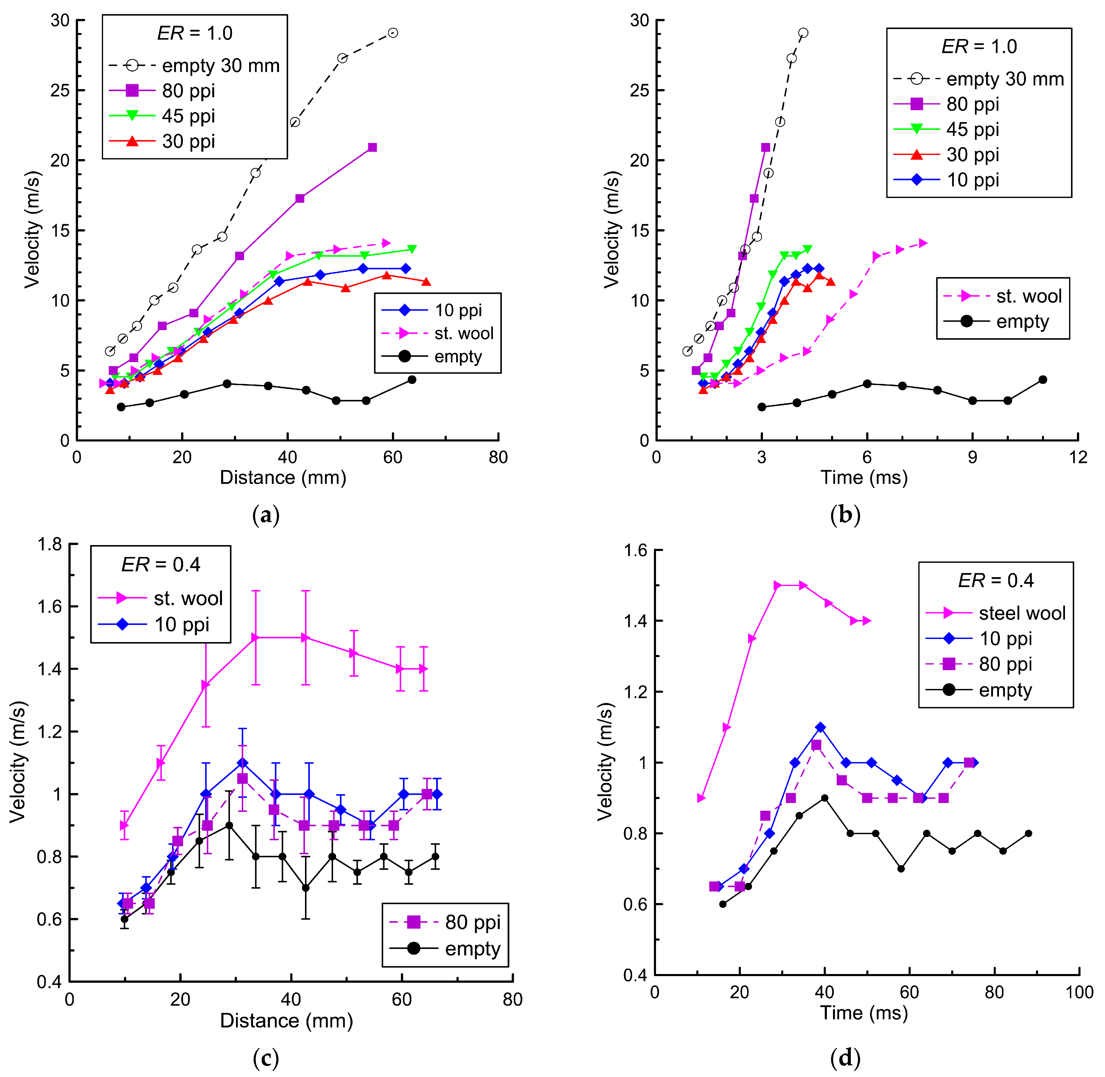
Figure 5 shows the velocities of the flame along the direction I toward the open end of the channel relative to the ignition point (
Figure 5a,c) and relative to time from ignition (
Figure 5b,d). This direction, I, is marked in
Figure 2a with a red line. The velocity was calculated based on the time interval between frames. The pixel position of the flame front was determined manually by the position of the most contrast point in the selected direction. The error in determining the flame front velocity in a separate experiment was less than 3%.
Figure 5 shows the average velocities calculated based on five experiments. The average deviation for velocities was about 10%. The maximum deviation did not exceed 20%.
Figure 5c shows the typical deviation for the velocities.
Comparing the results obtained, it is worth noting that for the stoichiometric mixture (ER = 1.0), with increasing pore density, the average velocity of the flame front increases. The maximum velocity (21 m/s) is achieved using a coating with a pore density of 80 ppi, and the minimum velocity (4 m/s) is recorded in the empty channel without coating. Placing steel wool leads to an increase in the flame speed to 10–12 m/s relative to the empty channel (4 m/s); however, this value is lower than the flame front when using porous polyurethane.
On the contrary, when placing steel wool in the lean mixture with
ER = 0.4, the flame front accelerates to a maximum value of 1.5 m/s. The flame front velocity of 0.9–1.1 m/s when placing porous polyurethane is higher than in the empty channel (0.7–0.9 m/s) but lower than with the steel wool. Such change in the velocity of the flame front with steel wool can be caused by the fact that a combustion reaction occurs on the surface of the wool, which, due to additional heat release, can lead to additional acceleration of the flame front in the hydrogen–air mixture. The change in the structure of the steel wool samples after combustion in the hydrogen–air mixture was discovered using an energy-dispersive analysis system. Detailed characteristics of steel wool before and after combustion in the hydrogen–air mixture based on X-ray analysis are presented in [
36].
In the stoichiometric mixture, steel wool can also burn after the flame front passes. However, the velocity of the flame front above the surface is significantly higher than this heterogeneous combustion velocity, so the contribution to the velocity is insignificant.
As can be seen in
Figure 5a,b, the change in flame front velocity when placing an impermeable steel plate is different from other velocities. In this case, the flame velocity equaled 20–22 m/s. This may be due to the fact that the combustion products and the unburned mixture do not shift in the transverse direction relative to the channel axis inside the porous layer. An increase in the pore density of the coating leads to a decrease in permeability for the transverse flow of the unburned mixture and combustion products, which, on the contrary, increases their average velocity relative to the channel axis. When studying the influence of pore density on the propagation of the flame front, the value of hydraulic resistance can be taken into account, which was studied in detail for polyurethane in [
35]. It is assumed that at the maximum value of hydraulic resistance, combustion products and unburned mixtures spread to a lesser extent inside the porous layer, which subsequently leads to the acceleration of the flame front in the free space above the porous surface.
Table 2 shows the maximum values of flame front velocities toward the open end, depending on the type of material and polyurethane pore density.
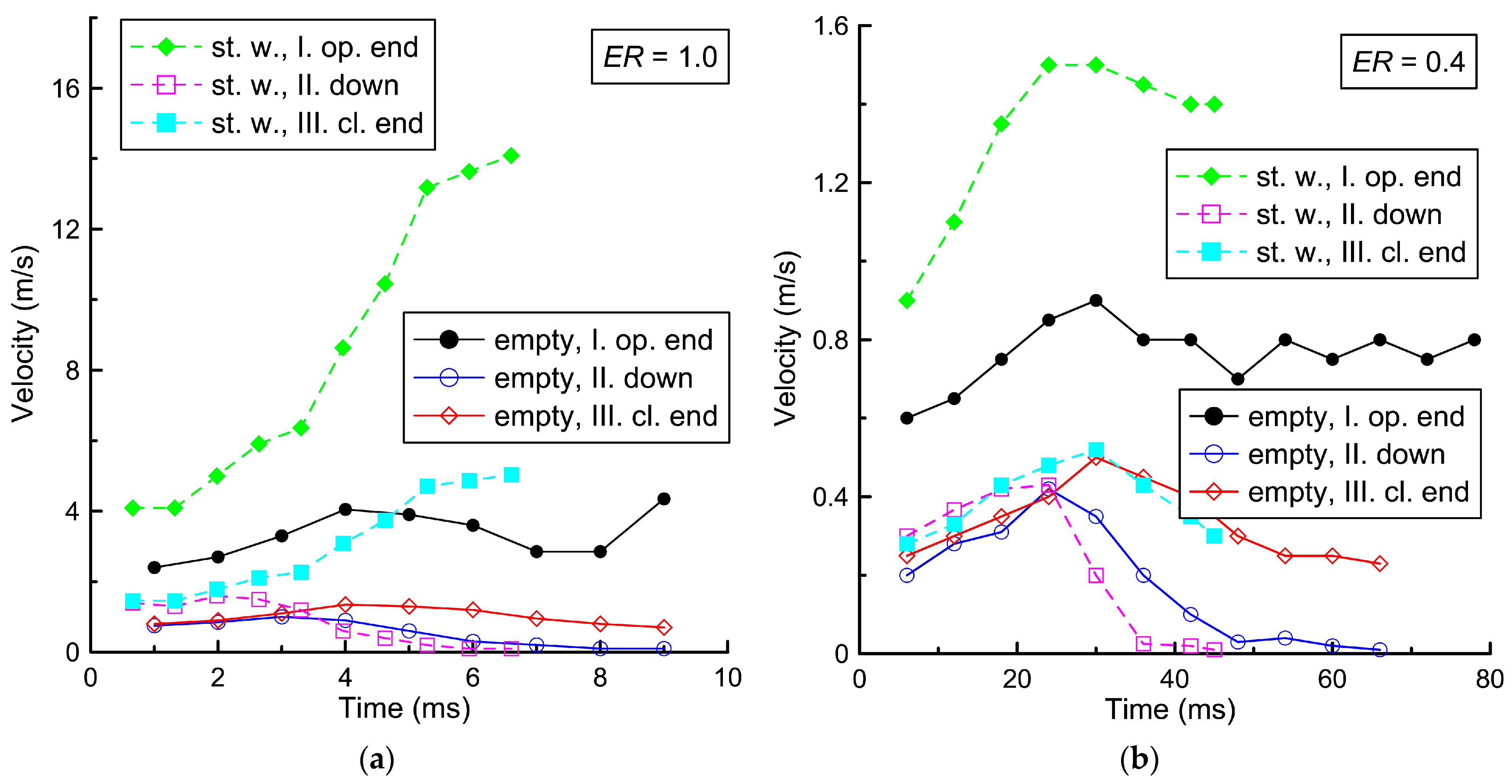
Figure 6 shows the flame front velocity in three directions: toward the open end of the channel (direction I), toward the closed end (direction III), and toward the porous coating (down, direction II). The directions are shown in
Figure 2a. The results are given for two mixtures and two configurations: for the empty channel and the channel with steel wool on the lower bottom wall.
As can be seen in
Figure 6, the velocity of the flame front toward the closed end and down is approximately three times lower than toward the open end. This difference is due to the fact that the expanding combustion products flow toward the open channel end, leading to a displacement of the flame front toward the open end of the channel. When the flame front reaches the lower solid surface of the channel (empty channel) or steel wool, the velocity of the flame front equals zero. In this case, the initial flame front velocity downwards or toward the closed end is comparable to the value of the laminar burning velocity in both the lean mixture (0.3 m/s) and the stoichiometric mixture (1.0–1.5 m/s). It is worth noting that the visible velocity of the flame front toward the open end of the channel is determined not only by the laminar burning velocity but also by a thermal expansion of the combustion products. Therefore, the velocity of the flame front toward the open end is, on average, several times higher than the above values.
Taking into account the velocity
vfl of the flame front, one can estimate the velocity
v of the unburned mixture and the Reynolds number, Re. In this work, the estimation was carried out for the maximum value in a quasi-one-dimensional isobaric approximation [
33,
37]:
Here,
θ =
ρ1/
ρ2 is a thermal expansion of the combustion products relative to the initial mixture,
ρ1 is the density of the unburned mixture, and
ρ2 is the density of combustion products. For the stoichiometric mixture, this value is equal to 7.2 [
38], and for
ER = 0.4, this value is equal to 3.7. The Reynolds number, Re, can be estimated using the following equation:
Here,
L = 20 mm is the minimal width of the diagnostic section and
η is the viscosity of the gas mixture. The method for determining the viscosity of hydrogen–air mixtures and their characteristic numerical values (
η = 17.7 × 10
−6–18.3 × 10
−6 Pa × s) are presented in [
33]. The characteristic Reynolds numbers for the channel are equal to 1.3 × 10
4 for the stoichiometric mixture and 1.4 × 10
3 for
ER = 0.4, respectively. As can be seen, for the stoichiometric mixture the Reynolds numbers are quite high; however, this does not mean that a stable turbulent flow can be formed. Such a flow can be established in a rather long channel. For a lean mixture with
ER = 0.4, Reynolds numbers correspond to laminar flow.
As can be seen in
Figure 2,
Figure 3 and
Figure 4, the propagation of the flame front is accompanied by the development of disturbances. At the initial stage of propagation, the flame front is exposed to thermal diffusion and thermoacoustic and hydrodynamic instabilities. In contrast to deflagration flames propagating in the stoichiometric mixture, in the mixture with
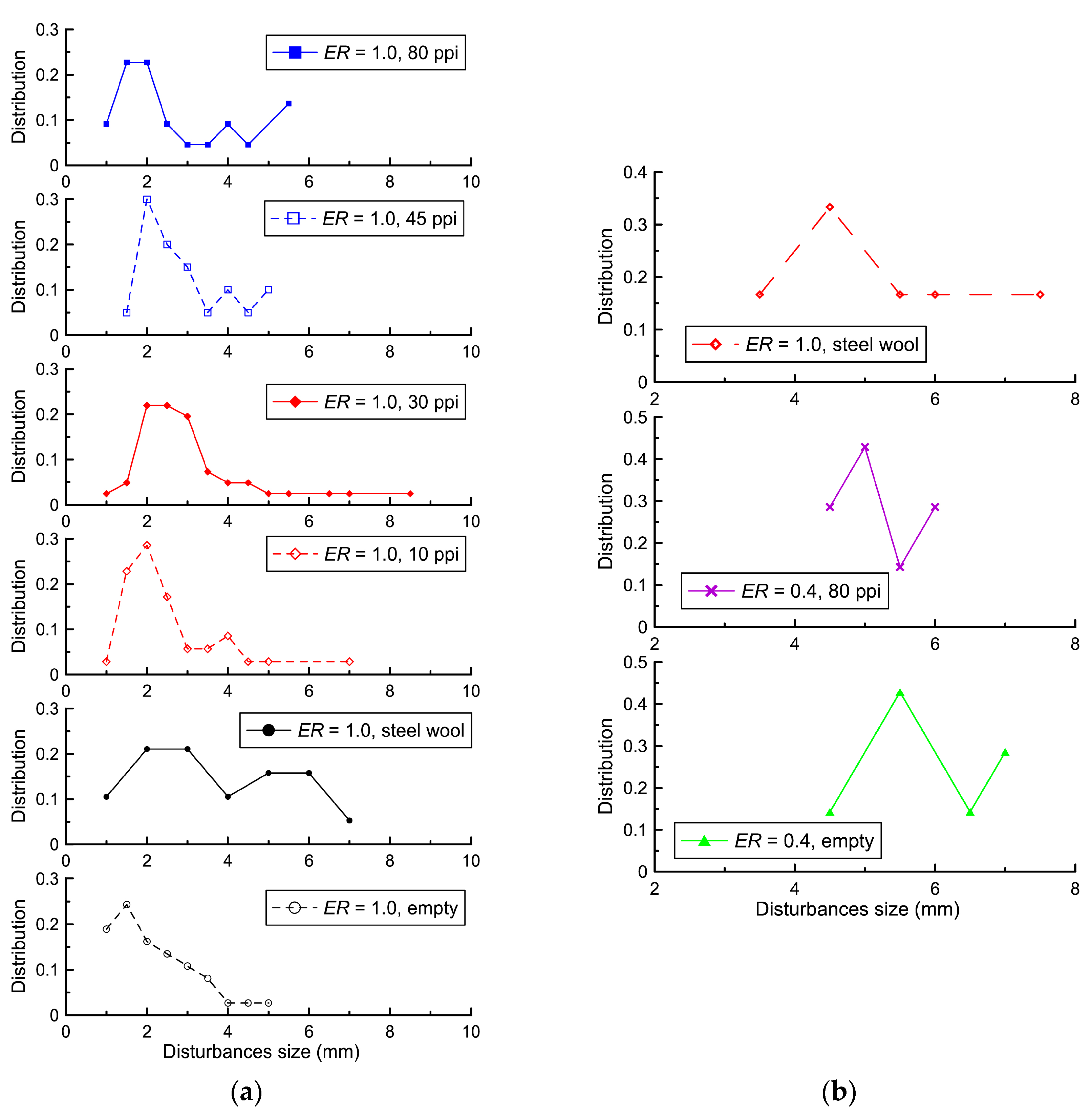
ER = 0.4, the structure of the flame front is a system of disturbances similar to small fireballs. The sizes of these disturbances or fireballs were determined from shadow photographs.
Figure 7 shows a method for determining the sizes of these disturbances.
Figure 8 shows the distribution of disturbance sizes at the flame front until the flame front touches the lower wall or porous coating. As can be seen in
Figure 8, the placement of coatings of various types did not lead to significant changes in the distributions of the sizes of disturbances in the same mixture. The characteristic size of the disturbances for the stoichiometric mixture was 2 mm, and for the mixture with
ER = 0.4, it was 4–5 mm. These values significantly exceed the analytical values for the Darrieus–Landau instability: 0.7 mm for the stoichiometric hydrogen–air mixture and 2.4 mm for the lean hydrogen–air mixture [
33]. A significant factor leading to an increase in the size of the disturbances is the displacement of combustion products toward the open end, which led to the displacement of the gas flow layers and, accordingly, an increase in the size of the disturbances.
4. Discussion
When discussing the application of the results obtained, it is worth noting that the placement of porous coatings can have a significant influence on the flame front at the initial stage of propagation. It is generally accepted that an increase in the size of obstacles, including the size of pores, leads to acceleration of the flame front due to the development of inhomogeneities, the development of turbulence, and the propagation of shock wave disturbances formed on the frame of porous coatings. However, at the initial stage of ignition in the area where a spark gap or other flame source is located, the porous wall exhibits a complex effect on both the reaction zone and the flow of the unburned mixture and combustion products. For example, in a more porous layer (10 ppi) with a large pore size, more intense heat exchange between the reaction zone and the polyurethane frame can occur. Conversely, in a less porous layer (80 ppi) with small pore sizes, combustion products practically do not interact with the internal structure of polyurethane due to high hydraulic resistance. Due to this, the effective cross-section of the entire channel is reduced and, with the same thermal expansion of the combustion products, the final visible flame front velocity can be significantly higher: 21 m/s for 80 ppi vs. 12 m/s for 10 ppi (ER = 1.0).
The use of steel wool for fire suppression is questionable due to the fact that it can be ignited. Moreover, this is true for lean mixtures characterized by an excess of oxygen. Thus, despite high porosity and, therefore, intense heat transfer, the use of steel wool with a small cross-sectional fiber size can only be effective for stoichiometric (ER = 1.0) or rich mixtures (ER > 1.0).
The maximum registered velocity of the flame front depends on the geometry of the channel in which the ignition occurs. The resulting features can be characteristic of longitudinal flow or when the channel is partially blocked by a porous coating, where it is possible to separate the flow in the free part of the channel and inside the porous layer.


