Article

Additively Manufactured Carbon Fiber-Reinforced Siliconized Silicon Carbide Composites Using Carbon Fiber-Reinforced Poly-Ether-Ether-Ketone (PEEK) as a Precursor


1
Materials Science and Technology Division, Oak Ridge National Laboratory, Oak Ridge, TN 37831, USA
2
Manufacturing Science Division, Oak Ridge National Laboratory, Oak Ridge, TN 37831, USA
3
Chemical Sciences Division, Oak Ridge National Laboratory, Oak Ridge, TN 37831, USA
4
Buildings and Transportation Science Division, Oak Ridge National Laboratory, Oak Ridge, TN 37831, USA
5
Energy Science and Technology Directorate, Oak Ridge National Laboratory, Oak Ridge, TN 37831, USA
*
Author to whom correspondence should be addressed.
Ceramics 2026, 9(6), 60; https://doi.org/10.3390/ceramics9060060
Submission received: 17 February 2026 / Revised: 24 May 2026 / Accepted: 5 June 2026 / Published: 7 June 2026
(This article belongs to the Special Issue Ceramic Materials for Industrial Decarbonization)

Abstract

Herein, we report a method to additively manufacture carbon fiber-reinforced siliconized silicon carbide composites. The process involves the pyrolysis of a 3D-printed carbon fiber-reinforced poly-ether-ether-ketone (PEEK) composite to produce a porous carbon fiber-reinforced carbon matrix composite preform, which is subsequently infiltrated with molten silicon to obtain a carbon fiber-reinforced siliconized silicon carbide composite. A key aspect of the method is limiting polymer melt flow during pyrolysis of PEEK, which is achieved by thermally annealing the 3D-printed carbon fiber-reinforced PEEK preform in air at a temperature below PEEK’s melting temperature. Rheological and differential scanning calorimetry (DSC) measurements demonstrate that the thermal annealing treatment altered the melting behavior of PEEK, while NMR and FTIR measurements provided a mechanistic explanation for the structural changes responsible for the behavior. It was also found that dimensional changes during pyrolysis were anisotropic with greater shrinkage in the stacking direction of the material.

1. Introduction

The addition of dispersed reinforcing phases has been demonstrated to be one of the most effective methods for overcoming the brittle behavior of ceramics. Among the various reinforcing phases, those with a large geometrical aspect ratio, such as high-strength fibers, coupled with engineered fiber–matrix interfaces, have been found to provide significant toughening through energy absorbing and dissipating mechanisms, including the deflection of cracks at the fiber–matrix interface, and fiber debonding and sliding to bridge matrix cracks [1,2]. Because of their high strength and elastic modulus, and their retention of physical and mechanical properties at high temperatures, carbon and silicon carbide fibers are widely used for reinforcing ceramic materials, including carbon and silicon carbide. Silicon carbide is a leading candidate for manufacturing ceramic matrix composites because of its remarkable properties, such as high elastic modulus, low coefficient of thermal expansion, high thermal conductivity, low density, high thermal stability, and high resistance to wear, oxidation, and extreme environments [3,4].
Carbon fiber-reinforced ceramic matrix composites, including those with carbon and silicon carbide matrices, have been the subject of significant research and development since their inception in the 1950s–1960s [5,6,7]. During this time, several methods have been developed for manufacturing objects using these materials, including chemical vapor infiltration; the repeated infiltration and pyrolysis of polymeric precursors to carbon or silicon carbide; and the reactive melt infiltration of liquid metals around fibrous preforms with n-D fiber orientation. In all of these cases, the geometry of the final products is limited by the shape of the molds used during fabrication or the shape of the fibrous preform, and processing may involve finishing steps, such as machining, which tend to be expensive and time-consuming. However, existing manufacturing methods using these materials are unable to produce objects with complex internal structures and shapes.
Recent developments in additive manufacturing have enabled the fabrication of ceramic objects, including silicon carbide, with complex internal structures and shapes that could not have been possible to attain with conventional manufacturing methods [8,9,10]. Furthermore, challenges for incorporating reinforcing fibers into these objects to improve their fracture toughness are being addressed [11,12,13,14,15]. For example, carbon fiber-reinforced silicon carbide composites have been fabricated through multiple steps that included the fabrication of green bodies by selective laser sintering (SLS) using composite feedstock particles containing phenolic resin, chopped carbon fibers and silicon powders. The printed bodies are then post-processed through phenolic infiltration and pyrolysis, and a final reactive silicon infiltration step [16]. The addition of silicon powder in the preparation of the composite feedstock particles was found to play an important role in the densification of these materials, while the size of the composite feedstock particles is expected to determine the dimensions of the smallest features that can be attained with this manufacturing method. Furthermore, it has been found that the carbon fibers that do not react with silicon can improve the fracture toughness of the material [17].
The fused filament fabrication (FFF) method along with the availability of fiber-reinforced polymeric filaments provides another alternative for manufacturing fiber-reinforced carbon and siliconized silicon carbide matrix composites with complex internal structures and shapes. For example, an object with arbitrary geometry can be manufactured via FFF using a carbon fiber-reinforced thermoplastic filament. Then, the 3D-printed object is pyrolyzed to obtain a fiber-reinforced porous carbon matrix composite; in the next step, the carbon matrix is infiltrated with a polymeric precursor for carbon (e.g., phenolic resin) or for silicon carbide (e.g., polycarbosilane resin) to increase the density of the matrix. Alternatively the porous carbon matrix can be infiltrated with molten silicon, which yields a dense composite by the formation of silicon carbide from the reaction of silicon with carbon, as well as unreacted residual silicon [4]. While thermoset polymers would be preferred because they can be readily pyrolyzed, 3D-printing with thermoset polymers, or thermoset polymers containing fibers, remains a significant challenge since the viscosity of the resin has to be sufficiently low to flow through the dispensing nozzle, but sufficiently high to prevent outrunning once the material is deposited, which would compromise the control of the shape of the object being printed [18,19].
Thermoplastics on the other hand are attractive because once they are dispensed through a printing nozzle, they solidify rapidly, ensuring control of the shape of the object being printed [20,21,22]. Other benefits of thermoplastics include long shelf life as well as compatibility with a wide variety of reinforcing phases, including fibers [23,24]. However, because pyrolysis temperatures are higher than thermoplastic melting temperatures, the thermoplastic needs to be modified (e.g., by crosslinking) so that it will not re-melt when pyrolyzed to convert it into a carbonaceous matrix. Among the many thermoplastic polymers available for FFF, poly-ether-ether-ketone (PEEK) is an attractive candidate. PEEK is a high-performance thermoplastic with excellent thermal stability and mechanical properties [25]. It has high carbon content, which translates into high carbon yield after pyrolysis [26], and PEEK filaments containing short carbon fibers have become readily available [27,28]. Furthermore, unlike most other thermoplastics commonly used in FFF, PEEK can be crosslinked through thermal annealing in air below its melting temperature, which is essential for suppressing melt flow and ensuring shape retention during pyrolysis. While thermoset polymers would be preferred from a pyrolysis standpoint, their use in FFF remains challenging due to difficulties in controlling resin viscosity during printing [18,19].
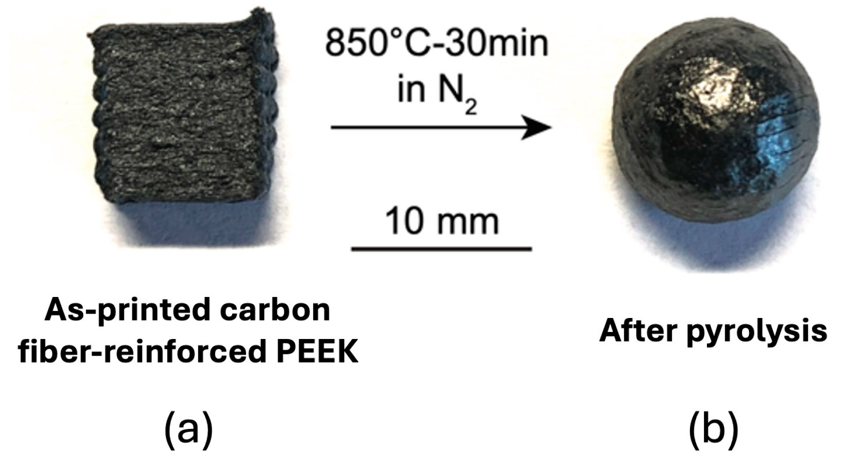
The melting temperature of PEEK at atmospheric pressure is 343 °C [29], and its successful utilization as a precursor for the fabrication of fiber-reinforced carbon and siliconized silicon carbide matrix composites with complex internal structures and shapes will depend on the ability to structurally modify it (e.g., by crosslinking) to prevent it from melting during pyrolysis. This challenge is illustrated in Figure 1, which shows a 3D-printed carbon fiber-reinforced PEEK parallelepiped. Also shown in Figure 1 is a picture of the same specimen after pyrolysis at 850 °C in N2 for 30 min, which clearly illustrates the loss of geometrical shape as a result of PEEK melting.
Very limited work has been reported on non-chemical and non-irradiation treatments to suppress the melting of PEEK and its flow at temperatures above its original melting temperature. For example, it has been shown that thermal treatments in air can significantly increase the viscosity of PEEK [30]. However, these treatments require heating the material above its melting temperature, which would render such treatments impractical for the objective of pyrolyzing 3D-printed fiber-reinforced PEEK composite objects without distorting their shape [31,32,33,34,35].
Bianchi et al. developed a method for producing net-shape fiber-reinforced siliconized silicon carbide matrix composites by the sequential application of high-pressure injection molding of a carbon fiber-reinforced PEEK polymer matrix composite in the form of a rod, followed by pyrolysis and reactive silicon infiltration [36]. However, because that process occurs inside molds, and the object did not have an internal structure, there were no concerns with the melting of PEEK during the pyrolysis step. Furthermore, the method of Bianchi et al. [36] is not amenable for fabricating objects with complex internal structures.
Despite recent advances in additive manufacturing of ceramic matrix composites, a critical gap remains: no existing process enables the fabrication of fiber-reinforced C/Si-SiC composites with complex internal structures without the use of molds or machining. The objective of this work is therefore to develop and demonstrate a thermal annealing treatment that suppresses melt flow during pyrolysis of FFF-printed carbon fiber-reinforced PEEK, enabling mold-free fabrication of C/Si-SiC composites with complex internal structures. In contrast to existing PEEK-derived approaches, which rely on mold-based methods and are therefore limited to simple geometries [31], the present work demonstrates that this objective can be achieved through sub-melt thermal annealing at 310 °C in air, without the need for chemical crosslinking agents or irradiation treatments. Furthermore, the use of FFF as the shaping step makes this approach inherently scalable and compatible with existing industrial infrastructure, offering practical advantages over more specialized AM routes for SiC-based composites.

2. Materials and Methods

This section describes the materials, specimen preparation procedures, and characterization methods used in this investigation. First, the fabrication of carbon fiber-reinforced PEEK specimens by FFF and their thermal annealing treatment are described, followed by the pyrolysis and reactive silicon infiltration steps. The characterization techniques used to assess the quality indicators at each stage of the fabrication process, including FTIR spectroscopy, DSC, TGA, rheometry, dilatometry, and SEM, are then described.

2.1. Sample Preparation

Specimens used in this investigation were printed in a closed-chamber FFF printer (Funmat HT, Intamsys, Shanghai, China) using 1.75 mm diameter PEEK (Victrex®, Lancashire, UK) filament containing 20% chopped polyacrylonitrile (PAN)-based carbon fibers (Toray T800, Toray Composite Materials America, Inc., Tacoma, WA, USA) with diameter between 5 and 10 µm, and on average 100 µm in length (3DXTech, Grand Rapids, MI, USA). Table 1 lists the properties of the filaments provided by the manufacturer. Based on these properties, the printing parameters used in this study are listed in Table 2. SolidWorks® software version 2022 (Dassault Systèmes, Vélizy-Villacoublay, France) was used to create a computer-aided design (CAD) model in STL format, and the printing sequence was specified using the slicing software Simplify3D version 5.
Parallelepiped-shaped specimens with dimensions of 10 mm × 10 mm × 3.5 mm were printed with a symmetric and balanced stacking sequence [0/90/0/90/90/0/90/0] with respect to the printing direction. A systematic screening study was conducted to identify the optimal thermal annealing conditions. Annealing temperatures of 310, 330, 350, and 400 °C were evaluated, and annealing durations of 36, 48, and 72 h were tested at 310 °C. At temperatures of 330 °C and above, specimens lost their shape regardless of annealing duration, with merging of printed layers and significant mass loss observed. At 310 °C, 48 h was identified as the optimal annealing duration based on shape retention, minimal mass loss (1.26%), and processing efficiency, 72 h produced acceptable results but with slightly higher mass loss (2.03%), and durations of 36 h and below were insufficient for complete shape retention during pyrolysis. The pyrolysis was performed at 850 °C for 30 min, under a constant flow of N2 to obtain C/C preforms. The heating rate of 1 °C/min was selected to minimize matrix cracking and allow sufficient time for pyrolysis gases to escape, consistent with established practice for pyrolysis of carbon fiber-reinforced polymers. The subsequent reactive silicon infiltration step was performed at 1450 °C for 30 min in vacuum (pressure < 0.1 Pa), followed by 4 h in argon at 1670 °C [8].

2.2. Characterization

The following quality indicators were used to assess fabrication quality at each stage of the process: (i) shape retention, assessed through visual inspection and dimensional measurements; (ii) mass loss, determined gravimetrically after thermal annealing and pyrolysis; (iii) microstructural integrity, characterized by SEM; (iv) thermal behavior, assessed through DSC and TGA; (v) viscoelastic response, characterized by rheological measurements; (vi) dimensional changes during pyrolysis, measured by dilatometry and direct caliper measurements; and (vii) phase composition of the final composite, determined by EDS analysis and BSE-SEM image analysis.
Fourier transform infrared (FTIR) absorption spectra were acquired in the wavenumber range of 650 to 4000 cm−1 using an FTIR spectrometer (Nicolet iS50, Thermo Fisher Scientific, Madison, WI, USA) equipped with an attenuated total reflection (ATR) cell. Specimens were prepared metallographically by mounting them in an epoxy resin, followed by grinding, and polishing, and their microstructure was characterized using a field-emission scanning electron microscope (FE-SEM, Tescan MIRA3, Brno, Czech Republic) operating at 10 kV.
Differential scanning calorimetry (DSC) measurements were carried out using a Discovery DSC 2500 (TA Instruments, New Castle, DE, USA) in the temperature range of 50 to 400 °C under a constant flow of N2. Single-layer flat specimens that had a weight of 20 mg were printed for DSC measurements to ensure good heat transfer between the test specimen and hermetic aluminum pans. A heating and cooling rate of 1 °C/min was used for these measurements. Subsequent heating scans were performed to investigate remelting behavior.
Thermogravimetric analysis (TGA) was performed under a constant flow of N2 using a TGA 5500 (TA Instruments) up to 900 °C using a heating rate of 10 °C/min, while thermal expansion measurements were performed using a high-temperature pushrod dilatometer (DIL 402, NETZSCH, Selb, Germany) in argon purge gas up to 900 °C. The heating rate was 10 °C/min, and the constant-force mode with a force of 100 mN was used.
Rotational rheometric measurements were carried out using an Advanced Rheometric Expansion System (TA Instruments). For these tests, the oven surrounding the test fixtures was maintained at the test temperature prior to the start of the measurements. Then, an assembly consisting of a disk-shaped test specimen (25 mm in diameter and 1 mm in thickness) sandwiched between two disk-shaped disposable plates was placed in the test fixture and allowed to reach thermal equilibrium. Tests were carried out under isothermal conditions using the dynamic time sweep mode at an angular frequency of 10 rad/s and a strain of 1%.
Raman spectra were acquired using a Raman microprobe (InVia, Renishaw, Inc. Gloucestershire, UK) equipped with a 532 nm Nd:YAG laser, with a spot size of approximately 1 µm. Phase maps were generated by acquiring spectra across a defined region of the polished cross-section and assigning each pixel to a phase based on characteristic peak positions.

3. Results and Discussion

This section presents and discusses the results of the experimental investigation in three parts, following the sequence of the fabrication process. First, the structural and thermal changes induced by thermal annealing of carbon fiber-reinforced PEEK are characterized and discussed in the context of crosslinking and crystallinity development. Second, the dimensional changes and microstructural evolution during pyrolysis are examined. Finally, the microstructure and phase composition of the final C/Si-SiC composite obtained after reactive silicon infiltration are presented and discussed.

3.1. Thermal Annealing of Carbon Fiber-Reinforced PEEK Specimens

A set of preliminary experiments were performed to determine the optimum temperature for heat treatment that avoids melting of PEEK. Since both crosslinking and thermal degradation of PEEK have been reported at temperatures between 300 and 400 °C [32,33,34,35,37,38], the printed carbon fiber-reinforced PEEK specimens were annealed at temperatures of 310, 350, and 400 °C for 48 h in air.
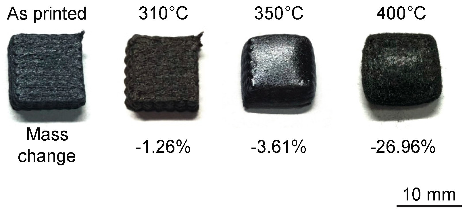
Figure 2 illustrates the effect of annealing temperature on the geometrical changes undergone by the test specimens after heat treatments. Specifically, it was found that the degree of geometrical distortion increased with increasing annealing temperature. Also, the surface characteristics of the specimen changed after the annealing treatment, and the degree of change depended on the annealing temperature. For example, the specimen annealed at 310 °C preserved its shape, its surface became slightly duller, and the mass loss was negligible (1.26% loss), whereas the sample annealed at 350 °C exhibited swelling, had a shiny surface, and experienced a mass loss of 3.61%. The sample treated at 400 °C was severely distorted, its surface was dull, and it experienced significant mass loss (~30%).
The mass losses observed during annealing in air are attributed to a combination of polymer structural changes and oxidative contributions, with their relative importance depending on annealing temperature. At 310 °C, the small mass loss of 1.26% is primarily consistent with volatile release during early-stage crosslinking, such as CO and CO2 generated by chain scission of ether and ketone bonds, though a minor oxidative contribution cannot be entirely excluded. At higher temperatures, thermo-oxidative degradation of PEEK becomes increasingly dominant, as evidenced by the substantially higher mass losses at 350 °C and 400 °C and the accompanying geometric distortion [39]. Since the objective of these thermal treatments was to identify a temperature at which PEEK could be annealed without significant geometrical distortions, it was decided to carry out additional treatments at 310 °C to determine the effect of annealing treatment duration on the structure of the material and its behavior.
It is noted that the carbon fibers are not expected to undergo oxidative degradation during the 310 °C annealing treatment in air, as PAN-based carbon fibers are well established to be stable in air below approximately 400–450 °C [40]. Additionally, the embedment of carbon fibers within the PEEK matrix provides physical shielding from direct oxidative attack at the fiber surface.
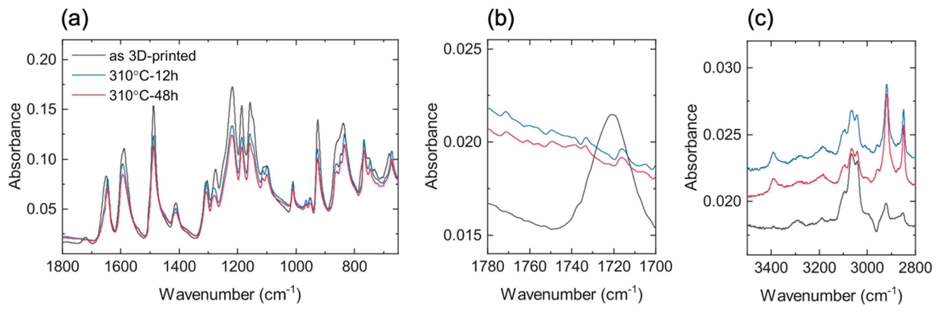
To assess the structural changes experienced by PEEK as a result of thermal treatments, FTIR spectra were collected for 3D-printed carbon fiber-reinforced PEEK specimens before and after they had been heated at 310 °C for 12 and 48 h (Figure 3). The fingerprints of PEEK are found in the range of wavenumbers below 1800 cm−1 for all specimens (Figure 3a). In particular, the absorption band at ≈1650 cm−1 is associated with the vibration of the carbonyl groups (C=O stretching), while the features at ≈1599, 1492 and 1413 cm−1 have been attributed to the C–C stretching of aromatic rings [38,41]. The band between 1350 and 1100 cm−1 is associated with the C–O stretching of the ester and ether groups, and the absorption bands of C–H deformations at the phenyl ring are visible below 900 cm−1 [42]. Although there is no substantial modification of the FTIR spectrum as a result of the thermal annealing treatment, a gradual decrease in relative absorption intensities can be observed as a function of annealing treatment duration. Especially, a reduction in carbonyl groups (≈1650 cm−1) can be attributed to the formation of a highly ordered crystalline structure of PEEK [34]. The disappearance of the broad band at 1740–1720 cm−1 after thermal annealing is attributed to the consumption of oxidation-related carbonyl species, specifically aliphatic aldehyde groups that form as intermediate products during thermo-oxidative treatment of PEEK in air. The elimination of these species is consistent with their involvement in crosslinking reactions, providing spectroscopic evidence that oxidative crosslinking contributes to the structural changes observed during annealing at 310 °C (Figure 3b).
In addition, the FTIR spectra in the region of 3500–2800 cm−1, which are shown in Figure 3c, include features associated with the alkane –CH2– asymmetric stretching vibration at 2920 cm−1, the –CH2– symmetric stretching vibrations at 2850 cm−1 [43], and the stretching vibrations of =C–H from aromatic rings at 3100–3000 cm−1 [44]. It can be observed that the relative intensities of –CH2– absorption band increase with increasing annealing time, while that associated with the =C–H absorption band decreases, which suggests that chain scission, aromatic ring opening, and hydrogenation of aromatic groups have also occurred [34]. Random chain scission of the ether and ketone bonds is believed to be the first step to produce stable intermediate radicals for crosslinking [44,45]; therefore, chain scission and aromatic ring opening are expected to promote crosslinking of PEEK.
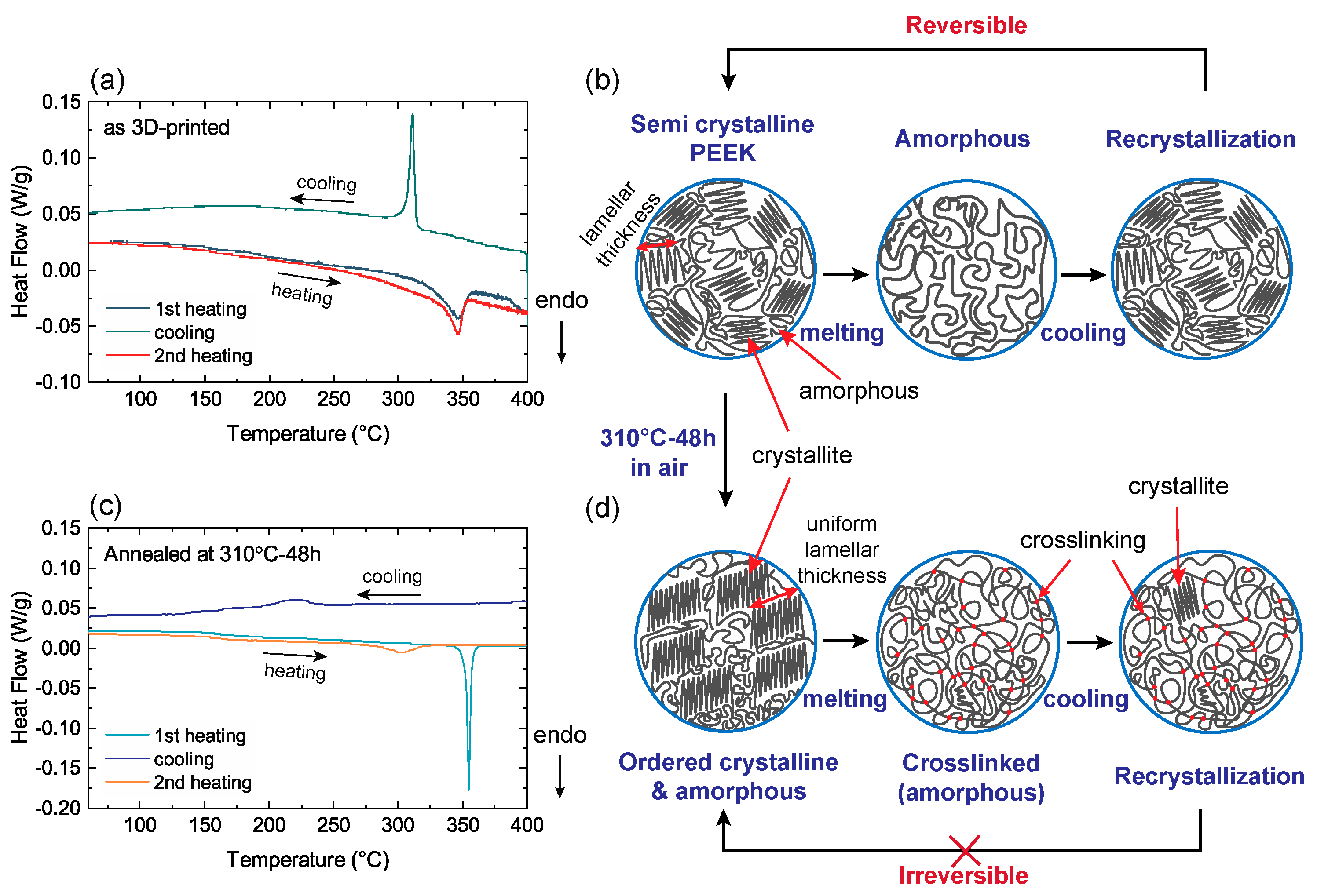
The thermal behavior of 3D-printed carbon fiber-reinforced PEEK before and after thermal annealing was investigated using DSC, and the results are shown in Figure 4. A clear endothermic peak can be observed at 348 °C for the 3D-printed carbon fiber-reinforced PEEK during the first DSC heating scan (Figure 4a), which is associated with crystalline melting. The breadth of the peak results from the broad distribution of crystal lamellar thicknesses. The exothermic peak at 317 °C suggests recrystallization of melted PEEK upon cooling. No significant difference was found in the second DSC heating scan, although a slight change in the melting point of 345 °C was observed. Considering that there were no differences observed in the second DSC heating scan, these results suggest that the melting and recrystallization of untreated carbon fiber-reinforced PEEK is a reversible process (Figure 4b).
A completely different behavior was observed for carbon fiber-reinforced PEEK after annealing at 310 °C for 48 h (Figure 4c). Upon heating, a sharp melting endothermic peak was observed at 353 °C, which is higher than the melting temperature of untreated carbon fiber-reinforced PEEK. This suggests that thermal annealing at 310 °C promotes the reorganization and growth of PEEK crystal lamellar that would lead to an increase in the melting temperature (Figure 4d) [35,46]. This result appears consistent with the FTIR results shown in Figure 3, which suggested that a highly ordered crystalline structure is formed after the thermal annealing treatment.
No exothermic peak was observed during cooling until a broad peak appeared at around 225 °C (Figure 4c). This indicates that complete recrystallization did not take place upon cooling, which might be due to the crosslinking reaction that occurred at high temperatures (Figure 4d) [47]. Crosslinking involves the formation of covalent bonds between polymer chains, so it increases the molecular weight, and it restricts molecular movement. A small exotherm at 225 °C suggests that crosslinking was incomplete so there was recrystallization of a small population of PEEK crystals. This is further evidenced by a subsequent DSC heating scan, which shows a very broad and small endothermic peak at 300 °C, which can be attributed to the melting of the newly formed crystals that had recrystallized during cooling.
The DSC data provides independent corroboration of increased crystallinity, separate from the FTIR evidence. The elevated melting point of 353 °C observed after annealing, compared to 348 °C for the as-printed material, is consistent with crystal lamellae thickening during annealing at 310 °C [35]. This allows partial distinction between crystallinity-driven and oxidation-driven contributions to the FTIR spectral changes: the reduction in the ~1650 cm−1 carbonyl peak and the elevated melting point together point to increased crystalline order, while the disappearance of the 1740–1720 cm−1 band is more specifically attributable to oxidative crosslinking reactions.
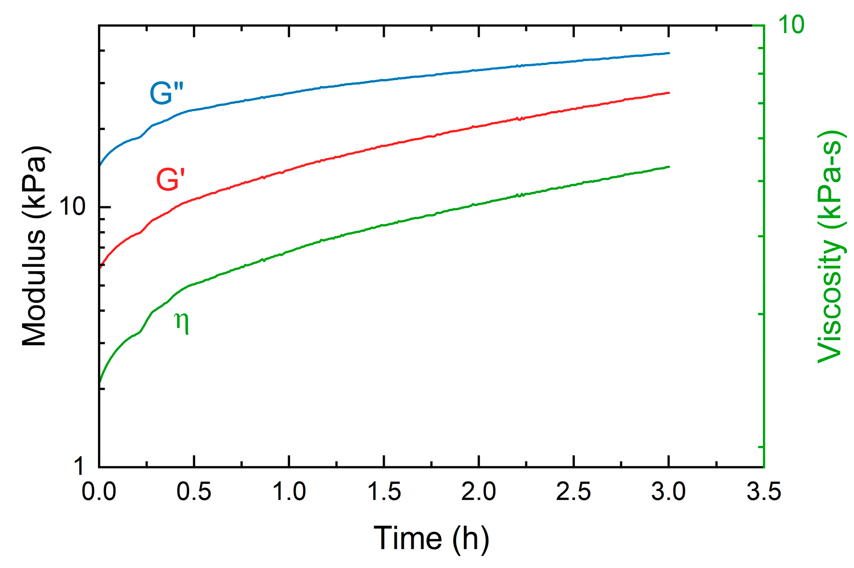
Rheological measurements provide additional evidence of crosslinking as a result of thermal annealing. Figure 5 shows values of viscosity as a function of time obtained at 385 °C in air for a 3D-printed carbon fiber-reinforced PEEK specimen in the as-printed condition. It can be observed that the viscosity increased rapidly with time. Also shown in Figure 5 are values of the components of the complex shear modulus, which were also found to increase with time. These results are consistent with those of Modi et al. who reported a significant increase in the viscosity and storage modulus of PEEK at 360 °C in air, and attributed the changes to thermo-oxidative crosslinking [30]. It should be mentioned that attempts to measure the viscosity 3D-printed carbon fiber-reinforced PEEK after thermal annealing at 310 °C for 48 h were unsuccessful since the test specimen did not melt. The annealed test specimen exhibited rubber-like behavior which is probably due to the formation of covalent crosslinks between PEEK polymer chains, since rubbery behavior is one of the characteristics of crosslinked thermoplastics at high temperatures [47].

3.2. Pyrolysis of Carbon Fiber-Reinforced PEEK Specimens

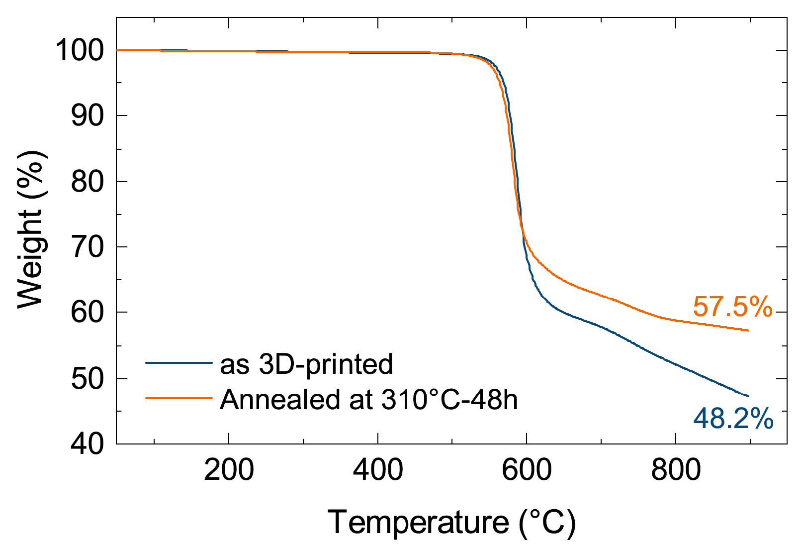
Figure 6 shows the TGA curves for printed carbon fiber-reinforced PEEK before and after the 48 h annealing treatment at 310 °C, indicating that the thermal annealing treatment did not affect the onset of thermal degradation. Rapid mass loss starts to occur at 600 °C, which is consistent with the previously reported results for carbon fiber-reinforced PEEK [26,45], as PEEK has excellent thermal degradation resistance. It can also be observed that the thermally annealed specimen had a higher total yield of 57.5% at 900 °C compared to the untreated carbon fiber-reinforced PEEK (48.2%). Pyrolysis of PEEK produces a carbonaceous char as well as volatiles such as phenols, CO, and CO2 [48]. During pyrolysis, two competing mechanisms are expected to play a major role: (i) chain scission which leads to the generation of volatile species and (ii) crosslinking which leads to char formation [49]. Therefore, the increased char yield is likely the result from the higher density of crosslinking after thermal annealing.
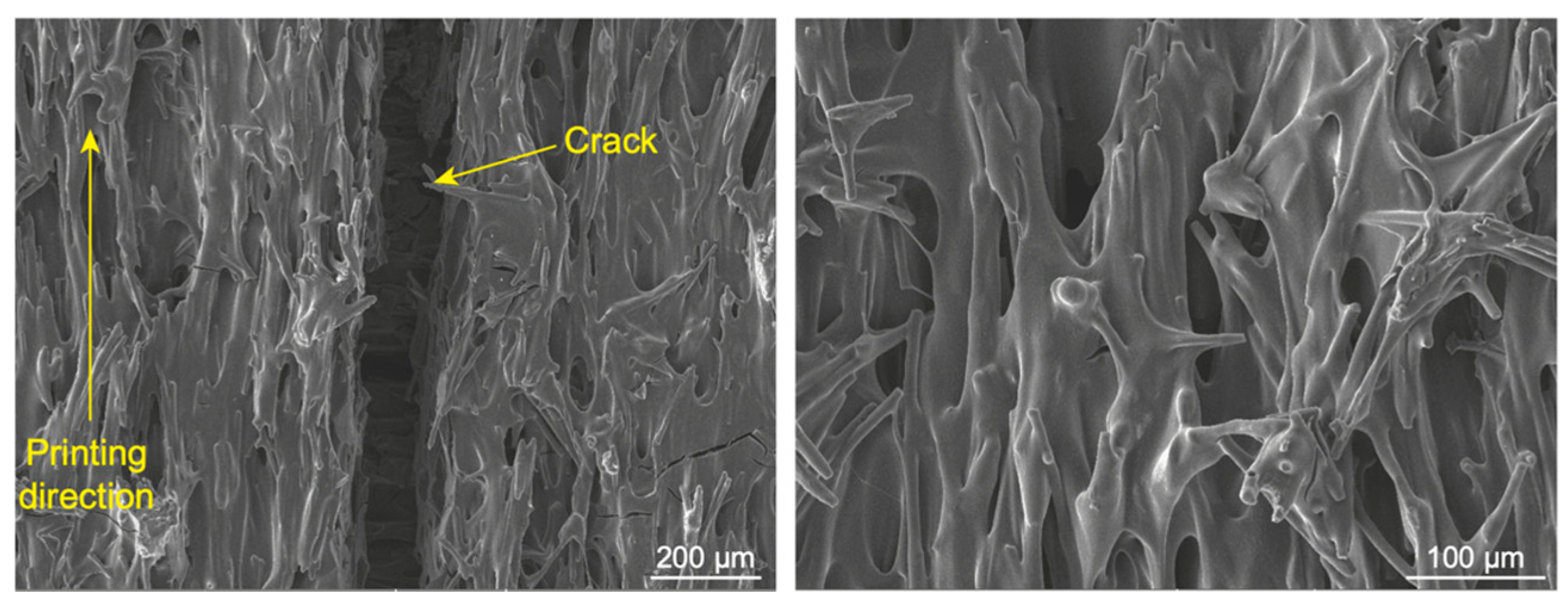
Figure 7 shows scanning electron micrographs to illustrate the microstructure of the material that results from the pyrolysis of 3D-printed carbon fiber-reinforced PEEK that had been previously thermally annealed at 310 °C for 48 h in air. The microstructure consists of carbon fibers embedded in carbon sheaths that contain cracks that nucleate and grow as a result of mass loss and constrained shrinkage of the material during pyrolysis and subsequent cooling. These observations are consistent with previous reports from the pyrolysis of carbon fiber-reinforced polymers (CFRPs) [20,50,51,52,53]. The morphology of the carbon sheaths also suggests that carbon fibers may have constrained any flow of PEEK during the pyrolysis treatment, as indicated by the thinning of the sheaths between fibers as a result of surface tension forces. The relative density of the pyrolyzed sample was ~46% that of fully dense graphite.
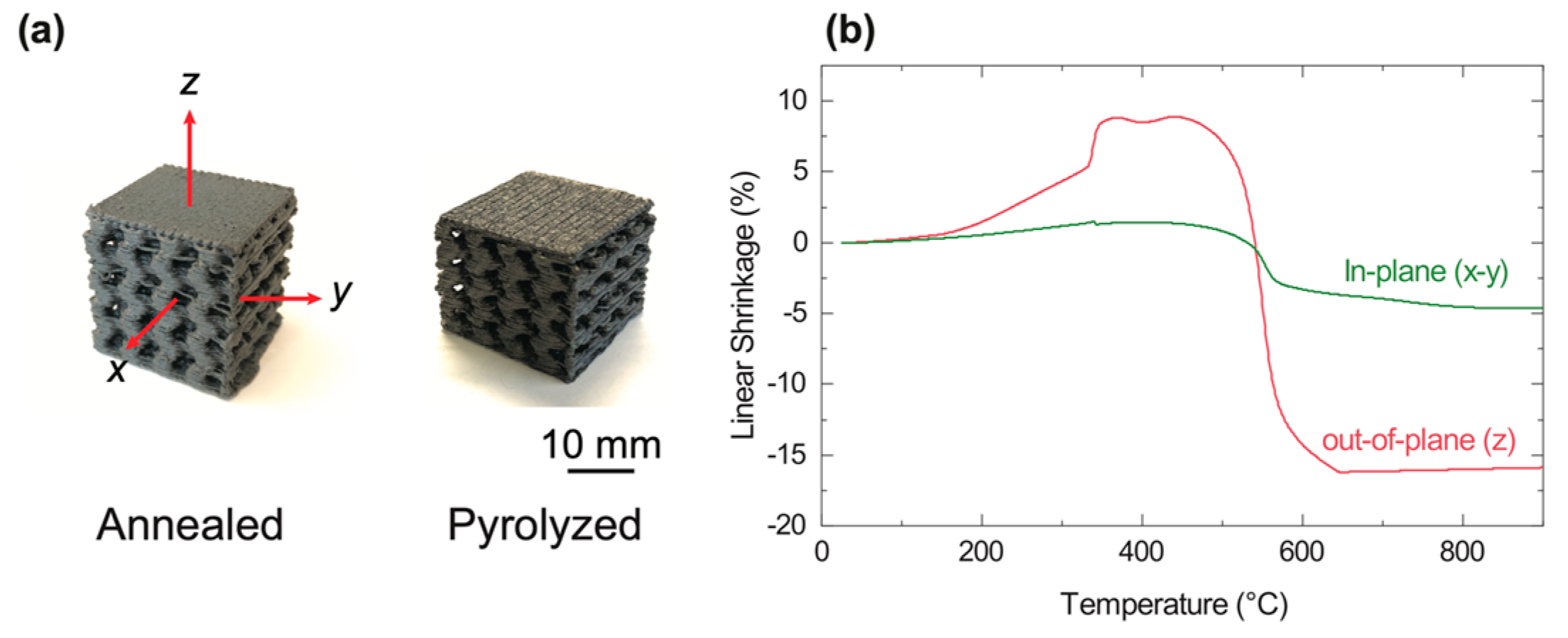
Since the structure of the specimens consists of alternating layers with orientation angles of 0° and 90° with respect to the printing direction, constrained shrinkage in the in-plane direction (x-y) is reasonably expected. However, the specimens are free to shrink in the out-of-plane direction (z) because carbon fibers are oriented perpendicular to the z direction, as confirmed by optical microscopy of cross-sectional areas. Therefore, carbon fiber-reinforced PEEK specimens experience anisotropic shrinkage during pyrolysis, as shown in Figure 8a. To quantify the effect of fiber orientation on shrinkage behavior, dilatometric measurements were performed and the results are shown in Figure 8b. Two different regions can be identified in these curves: thermal expansion of the material up to ~450 °C prior to pyrolysis, and shrinkage during pyrolysis (above 580 °C). It can be observed that the response of the material is dependent on the build direction. It was found that the amount of shrinkage was 5% and 16%, for the in-plane (x-y) and out-of-plane (z) directions, respectively. These results point at the importance of characterizing this behavior in detail to be able to predict dimensional changes of objects that may have complex geometries and varying fiber orientation.
While the pyrolysis of 3D-printed carbon fiber-reinforced PEEK results in volumetric shrinkage, it was found that these dimensional changes do not involve shape distortions, as demonstrated by the pictures of a gyroid before and after pyrolysis shown in Figure 8. This lack of shear deformation results from the combination of thermal annealing and the addition of fibers, both of which increase viscosity [54,55]. As discussed above, exposure of carbon fiber-reinforced PEEK to an oxidative environment above PEEK’s melting temperature has been shown to increase melt viscosity as a result of crosslinking [30,56]. However, in this study, crosslinking was achieved at a temperature below the melting point of PEEK, which was essential for ensuring the shape of printed objects was preserved during the pyrolysis of PEEK.

3.3. Reactive Silicon Infiltration

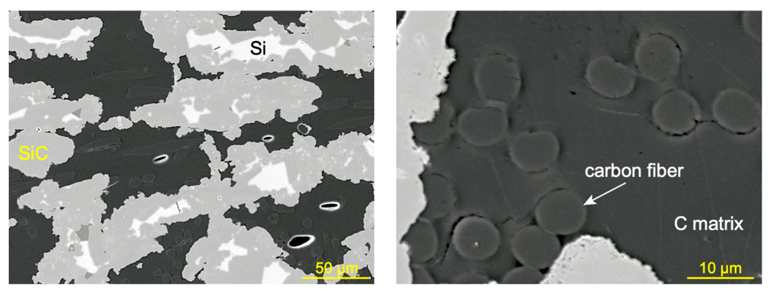
The scanning electron micrographs in Figure 9 show the microstructure of specimens obtained after reactive melt infiltration with silicon. The material microstructure consists of multiple phases, including carbon fibers and a matrix containing carbon, silicon carbide, and residual silicon. The bulk density of the infiltrated Cf/Si–SiC composite was measured to be 1.96 g/cm3. Open porosity was found to be negligible, as reactive melt infiltration results in the formation of a silicon-rich layer on the external surfaces of the specimen that effectively seals surface-connected porosity. However, microstructural analysis revealed approximately 15% closed internal porosity, consistent with the relatively low initial density of the C/C preform (~46% of fully dense graphite). Residual free silicon content was estimated to be about 25%.
During reactive melt infiltration with silicon, cracks in the carbon matrix that had formed during pyrolysis of PEEK become filled with liquid silicon because the velocity of the infiltration front is much faster than the kinetics of the reaction between silicon and carbon [57]. As the process continues, molten silicon reacts with the carbon matrix to form silicon carbide. Considering that most fibers are embedded in carbon sheaths, it is likely these serve as a barrier that prevents chemical reactions between the fibers and molten silicon as indicated by the scanning electron micrographs in Figure 9. However, direct chemical reaction of molten silicon with the carbon fibers could result in fiber damage, compromising their structural integrity and their ability to contribute to the strengthening and toughening of the composite. Future developments of the manufacturing process outlined in this paper should include the use of carbon or silicon carbide fibers that are coated with a fiber–matrix interphase to prevent interaction between the fibers and molten silicon, and to ensure the operability of micromechanical mechanisms that are responsible for the tough behavior of fiber-reinforced ceramic matrix composites.
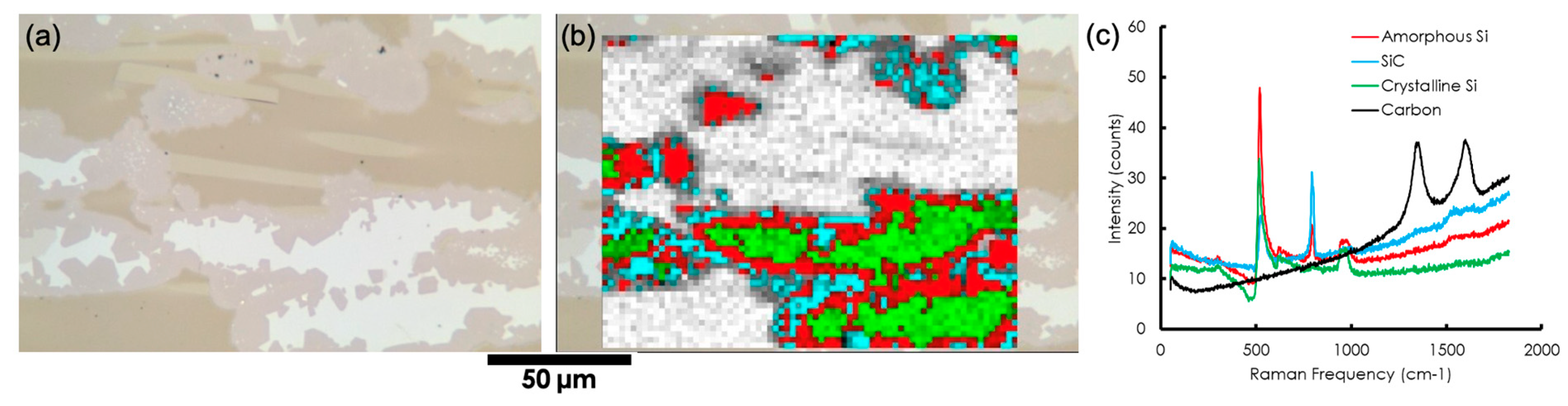
To confirm the formation of silicon carbide in the matrix, Raman microspectroscopy was performed on a polished cross-section of the reactive melt-infiltrated composite (Figure 10). The Raman phase map (Figure 10b) reveals three distinct phases, with representative spectra shown in Figure 10c. Residual silicon is identified by a sharp peak at ~520 cm−1, and the carbon matrix exhibits the characteristic D and G bands at ~1350 and ~1580 cm−1. The teal phase displays a strong peak at 793 cm−1, corresponding to the transverse optical (TO) mode of silicon carbide [58]. This SiC phase is spatially located between the silicon and carbon phases, consistent with its formation through the reaction of molten silicon with the carbon matrix during reactive melt infiltration.

4. Summary and Conclusions

A method for fabricating carbon fiber-reinforced carbon matrix and siliconized silicon carbide matrix composites has been presented. The process is based on the 3D-printing of carbon fiber-reinforced PEEK preforms via the fused filament fabrication method, followed by thermal annealing and pyrolysis. Subsequent matrix densification can be achieved by multiple cycles of infiltration and pyrolysis using polymeric precursors for carbon or silicon carbide, or by reactive melt infiltration with silicon. It was found that thermal annealing treatments in air at 310 °C for 48 h promoted the crosslinking of PEEK resulting in a highly viscous solid that does not melt and therefore were effective to ensure that the geometry of objects was not distorted during PEEK pyrolysis. Objects manufactured according to this method experienced anisotropic shrinkage during pyrolysis as a result of the presence of carbon fibers on the plane of deposited layers. After reactive melt infiltration with silicon, objects exhibited microstructures consisting of carbon fibers, a duplex matrix containing carbon and SiC, and residual silicon. Work is in progress to establish processing–microstructure–property relationships for these materials.
While several processes have been developed to date for manufacturing ceramic matrix composites, including carbon fiber-reinforced carbon and silicon carbide matrix composites, no one of those processes can be used for manufacturing objects with complex shapes and complex internal structures, such as those that can be attained by the fused filament fabrication method.
PEEK reinforced with discontinuous carbon fibers was selected as a feedstock in this study because it is readily available as a filament for the fused filament fabrication method. However, other thermoplastic precursors that could be crosslinked by thermal annealing and would have high carbon yield would be amenable for the fabrication process described in this manuscript. Future developments to incorporate longer or continuous fibers into filaments for fused filament fabrication are expected to further improve the mechanical properties of fiber-reinforced ceramic matrix composites fabricated by the method outlined here.

Author Contributions

Conceptualization, B.Y. and E.L.-C.; methodology, B.Y. and E.L.-C.; validation, B.Y. and E.L.-C.; investigation, B.Y.; resources, J.W.K. and H.W.; data curation, B.Y., R.M.P., M.J.L. and H.W.; writing—original draft preparation, B.Y.; writing—review and editing, E.L.-C.; visualization, B.Y.; supervision, E.L.-C.; project administration, K.N. and E.L.-C.; funding acquisition, K.N. and E.L.-C. All authors have read and agreed to the published version of the manuscript.

Funding

This work was funded by the U.S. Department of Energy, Building Technologies Program. This manuscript has been authored by UT-Battelle LLC under Contract No. DE-AC0500OR22725 with the U.S. Department of Energy. The United States Government retains and the publisher, by accepting the article for publication, acknowledges that the United States Government retains a nonexclusive, paid-up, irrevocable, worldwide license to publish or reproduce the published form of this manuscript, or allow others to do so, for United States Government purposes. The Department of Energy will provide public access to these results of federally sponsored research in accordance with the DOE Public Access Plan (http://energy.gov/downloads/doe-public-access-plan. Accessed on 6 June 2026).

Data Availability Statement

The original contributions presented in this study are included in the article.

Acknowledgments

The authors gratefully acknowledge technical support from Frederic Vautard, Aparna Annamraju, Caitlin Duggan, Chris Gilbert and Justin Finks, and technical discussion and critical review of the manuscript by their ORNL colleague John Lindahl.

Conflicts of Interest

The authors declare no conflicts of interest.

References

  1. Faber, K.T.; Evans, A.G. Crack deflection processes—I. Theory. Acta Metall. 1983, 31, 565–576. [Google Scholar] [CrossRef]
  2. Wachtman, J.B.; Cannon, W.R.; Matthewson, M.J. Mechanical Properties of Ceramics; John Wiley & Sons: Hoboken, NJ, USA, 2009. [Google Scholar]
  3. Naslain, R. Design, preparation and properties of non-oxide CMCs for application in engines and nuclear reactors: An overview. Compos. Sci. Technol. 2004, 64, 155–170. [Google Scholar] [CrossRef]
  4. Krenkel, W. Carbon fiber reinforced CMC for high-performance structures. Int. J. Appl. Ceram. Technol. 2004, 1, 188–200. [Google Scholar] [CrossRef]
  5. Snide, J.; Lynch, C.; Whipple, L. Current Developments in Fiber-Reinforced Composites; Semantic Scholar: Seattle, WA, USA, 1968. [Google Scholar]
  6. Chorne, J.; Feingold, E.; Gatti, A.; Mehan, R.; Rauch, H.; Sutton, W. Research on Fiber-Reinforced Composites; NASA: Washington, DC, USA, 1965. [Google Scholar]
  7. Gates, L.; Lent, W.; Teague, W. Development of Ceramic Fibers for Reinforcement in Composite Materials; NASA: Washington, DC, USA, 1961. [Google Scholar]
  8. Cramer, C.L.; Elliott, A.M.; Lara-Curzio, E.; Flores-Betancourt, A.; Lance, M.J.; Han, L.; Blacker, J.; Trofimov, A.A.; Wang, H.; Cakmak, E.; et al. Properties of SiC-Si made via binder jet 3D printing of SiC powder, carbon addition, and silicon melt infiltration. J. Am. Ceram. Soc. 2021, 104, 5467–5478. [Google Scholar] [CrossRef]
  9. Terrani, K.; Jolly, B.; Trammell, M. 3D printing of high-purity silicon carbide. J. Am. Ceram. Soc. 2020, 103, 1575–1581. [Google Scholar] [CrossRef]
  10. Altun, A.A.; Prochaska, T.; Konegger, T.; Schwentenwein, M. Dense, strong, and precise silicon nitride-based ceramic parts by lithography-based ceramic manufacturing. Appl. Sci. 2020, 10, 996. [Google Scholar] [CrossRef]
  11. Cramer, C.L.; Yoon, B.; Lance, M.J.; Cakmak, E.; Campbell, Q.A.; Mitchell, D.J. Additive Manufacturing of C/C-SiC Ceramic Matrix Composites by Automated Fiber Placement of Continuous Fiber Tow in Polymer with Pyrolysis and Reactive Silicon Melt Infiltration. J. Compos. Sci. 2022, 6, 359. [Google Scholar] [CrossRef]
  12. Wang, W.; Gao, X.; Li, Z.; Shen, C.; Wang, G.; He, R. Fiber-laying-assisted material extrusion additive manufacturing of continuous carbon fiber reinforced SiC ceramic matrix composites. Mater. Sci. Eng. A 2024, 890, 145944. [Google Scholar] [CrossRef]
  13. Han, H.; Hu, Q.; Yang, X. Additive manufacturing of fiber-reinforced silicon carbide ceramic matrix composites: Process optimization and performance control. Ceram. Int. 2025, 51, 45205–45224. [Google Scholar] [CrossRef]
  14. Li, Z.; Wang, W.; Gao, X.; Shen, C.; Wang, G.; He, R. Continuous carbon fiber reinforced SiC ceramic matrix composites by vertical fiber laying combined with material extrusion 3D printing. Adv. Eng. Mater. 2024, 26, 2400218. [Google Scholar] [CrossRef]
  15. Liu, Z.; Chen, X.; Chen, B.; Hu, Y.; Zheng, K.; Liu, G.; Chen, A.; Chen, P.; Li, Z.; Yang, L.; et al. The mechanical enhancement mechanism in additively manufactured continuous SiCf/SiC ceramic matrix composites. J. Eur. Ceram. Soc. 2026, 46, 118059. [Google Scholar] [CrossRef]
  16. Fu, H.; Zhu, W.; Xu, Z.; Chen, P.; Yan, C.; Zhou, K.; Shi, Y. Effect of silicon addition on the microstructure, mechanical and thermal properties of Cf/SiC composite prepared via selective laser sintering. J. Alloys Compd. 2019, 792, 1045–1053. [Google Scholar] [CrossRef]
  17. Zhu, W.; Fu, H.; Xu, Z.; Liu, R.; Jiang, P.; Shao, X.; Shi, Y.; Yan, C. Fabrication and characterization of carbon fiber reinforced SiC ceramic matrix composites based on 3D printing technology. J. Eur. Ceram. Soc. 2018, 38, 4604–4613. [Google Scholar] [CrossRef]
  18. Lindahl, J.; Hershey, C.; Kunc, V.; Gladysz, G.; Mishra, V.; Shah, K. Additive Manufacturing Using Epoxy and Anhydride Curatives; Oak Ridge National Laboratory (ORNL): Oak Ridge, TN, USA, 2019. [Google Scholar]
  19. Compton, B.G.; Lewis, J.A. 3D-Printing of Lightweight Cellular Composites. Adv. Mater. 2014, 26, 5930–5935. [Google Scholar] [CrossRef]
  20. Liensdorf, T.; Langhof, N.; Krenkel, W. Mechanical properties of PEEK-derived C/SiC composites with different fiber lengths. Adv. Eng. Mater. 2019, 21, 1800835. [Google Scholar] [CrossRef]
  21. Reichert, F.; Pérez-Mas, A.M.; Barreda, D.; Blanco, C.; Santamaria, R.; Kuttner, C.; Fery, A.; Langhof, N.; Krenkel, W. Influence of the carbonization temperature on the mechanical properties of thermoplastic polymer derived C/C-SiC composites. J. Eur. Ceram. Soc. 2017, 37, 523–529. [Google Scholar] [CrossRef]
  22. Flauder, S.; Langhof, N.; Krenkel, W. Tailored macro-pores during the formation of C/C-SiC via liquid phase pyrolysis. J. Eur. Ceram. Soc. 2021, 41, 2995–3001. [Google Scholar] [CrossRef]
  23. Li, L.; Tirado, A.; Nlebedim, I.C.; Rios, O.; Post, B.; Kunc, V.; Lowden, R.R.; Lara-Curzio, E.; Fredette, R.; Ormerod, J.; et al. Big area additive manufacturing of high performance bonded NdFeB magnets. Sci. Rep. 2016, 6, 36212. [Google Scholar] [CrossRef]
  24. Kishore, V.; Hassen, A.A. Chapter 6-Polymer and composites additive manufacturing: Material extrusion processes. In Additive Manufacturing; Pou, J., Riveiro, A., Davim, J.P., Eds.; Elsevier: Amsterdam, The Netherlands, 2021; pp. 183–216. [Google Scholar]
  25. Rae, P.J.; Brown, E.N.; Orler, E.B. The mechanical properties of poly(ether-ether-ketone) (PEEK) with emphasis on the large compressive strain response. Polymer 2007, 48, 598–615. [Google Scholar] [CrossRef]
  26. dos Santos Conejo, L.; de Meneses Neto, H.R.; de Oliveira, J.B.; de Paula Santos, L.F.; Nakazato, R.Z.; de Oliveira Hein, L.R.; Kok, W.; Botelho, E.C. Production and characterization of carbon/carbon composites from thermoplastic matrices. J. Polym. Res. 2021, 28, 123. [Google Scholar] [CrossRef]
  27. Wang, P.; Zou, B.; Ding, S.; Huang, C.; Shi, Z.; Ma, Y.; Yao, P. Preparation of short CF/GF reinforced PEEK composite filaments and their comprehensive properties evaluation for FDM-3D printing. Compos. B Eng. 2020, 198, 108175. [Google Scholar] [CrossRef]
  28. Brenken, B.; Barocio, E.; Favaloro, A.; Kunc, V.; Pipes, R.B. Fused filament fabrication of fiber-reinforced polymers: A review. Addit. Manuf. 2018, 21, 1–16. [Google Scholar] [CrossRef]
  29. Kurtz, S.M. Chapter 1-An Overview of PEEK Biomaterials. In PEEK Biomaterials Handbook, 2nd ed.; Kurtz, S.M., Ed.; William Andrew Publishing: Norwich, NY, USA, 2019; pp. 3–9. [Google Scholar]
  30. Modi, S.H.; Dikovics, K.B.; Gevgilili, H.; Mago, G.; Bartolucci, S.F.; Fisher, F.T.; Kalyon, D.M. Nanocomposites of poly(ether ether ketone) with carbon nanofibers: Effects of dispersion and thermo-oxidative degradation on development of linear viscoelasticity and crystallinity. Polymer 2010, 51, 5236–5244. [Google Scholar] [CrossRef]
  31. Bas, C.; Battesti, P.; Albérola, N.D. Crystallization and melting behaviors of poly(aryletheretherketone) (PEEK) on origin of double melting peaks. J. Appl. Polym. Sci. 1994, 53, 1745–1757. [Google Scholar] [CrossRef]
  32. Al Lafi, A.G.; Parker, D.J.; Hay, J.N. The crosslinking of poly (ether ether ketone): Thermally and by irradiation. J. Appl. Polym. Sci. 2015, 132, 41999. [Google Scholar] [CrossRef]
  33. Zhang, Z.; Zeng, H. Effects of thermal treatment on poly(ether ether ketone). Polymer 1993, 34, 3648–3652. [Google Scholar] [CrossRef]
  34. Day, M.; Sally, D.; Wiles, D.M. Thermal degradation of poly(aryl-ether-ether-ketone): Experimental evaluation of crosslinking reactions. J. Appl. Polym. Sci. 1990, 40, 1615–1625. [Google Scholar] [CrossRef]
  35. Fougnies, C.; Damman, P.; Dosière, M.; Koch, M.H.J. Time-Resolved SAXS, WAXS, and DSC Study of Melting of Poly(aryl ether ether ketone) (PEEK) Annealed from the Amorphous State. Macromolecules 1997, 30, 1392–1399. [Google Scholar] [CrossRef]
  36. Bianchi, G.; Vodermayer, A.; Ortona, A. Net shape CMC components produced by composite flow moulding, pyrolysis and reactive silicon infiltration. Ceram. Int. 2018, 44, 12204–12209. [Google Scholar] [CrossRef]
  37. Chan, C.-M.; Venkatraman, S. Crosslinking of poly(arylene ether ketone)s 1. Rheological behavior of the melt and mechanical properties of cured resin. J. Appl. Polym. Sci. 1986, 32, 5933–5943. [Google Scholar] [CrossRef]
  38. Nguyen, H.X.; Ishida, H. Molecular analysis of the melting behaviour of poly(aryl-ether-ether-ketone). Polymer 1986, 27, 1400–1405. [Google Scholar] [CrossRef]
  39. Day, M.; Suprunchuk, T.; Cooney, J.D.; Wiles, D.M. Thermal degradation of poly(aryl-ether–ether-ketone) (PEEK): A differential scanning calorimetry study. J. Appl. Polym. Sci. 1988, 36, 1097–1106. [Google Scholar] [CrossRef]
  40. Bertran, X.; Labrugère, C.; Dourges, M.A.; Rebillat, F. Oxidation behavior of PAN-based carbon fibers and the effect on mechanical properties. Oxid. Met. 2013, 80, 299–309. [Google Scholar] [CrossRef]
  41. Stepashkin, А.А.; Chukov, D.I.; Senatov, F.S.; Salimon, A.I.; Korsunsky, A.M.; Kaloshkin, S.D. 3D-printed PEEK-carbon fiber (CF) composites: Structure and thermal properties. Compos. Sci. Technol. 2018, 164, 319–326. [Google Scholar] [CrossRef]
  42. Pascual, A.; Toma, M.; Tsotra, P.; Grob, M.C. On the stability of PEEK for short processing cycles at high temperatures and oxygen-containing atmosphere. Polym. Degrad. Stab. 2019, 165, 161–169. [Google Scholar] [CrossRef]
  43. Simonin, L.; Liao, H. Characterization of flame-sprayed PEEK coatings by FTIR-ATR, DSC and acoustic microscopy. Macromol. Mater. Eng. 2000, 283, 153–162. [Google Scholar] [CrossRef]
  44. Puhan, D.; Wong, J.S.S. Properties of Polyetheretherketone (PEEK) transferred materials in a PEEK-steel contact. Tribol. Int. 2019, 135, 189–199. [Google Scholar] [CrossRef]
  45. Patel, P.; Hull, T.R.; McCabe, R.W.; Flath, D.; Grasmeder, J.; Percy, M. Mechanism of thermal decomposition of poly(ether ether ketone) (PEEK) from a review of decomposition studies. Polym. Degrad. Stab. 2010, 95, 709–718. [Google Scholar] [CrossRef]
  46. Groeninckx, G.; Reynaers, H.; Berghmans, H.; Smets, G. Morphology and melting behavior of semicrystalline poly(ethylene terephthalate). I. Isothermally crystallized PET. J. Polym. Sci. B Polym. Phys. 1980, 18, 1311–1324. [Google Scholar] [CrossRef]
  47. Yurchenko, M.E.; Huang, J.; Robisson, A.; McKinley, G.H.; Hammond, P.T. Synthesis, mechanical properties and chemical/solvent resistance of crosslinked poly(aryl-ether–ether–ketones) at high temperatures. Polymer 2010, 51, 1914–1920. [Google Scholar] [CrossRef]
  48. Day, M.; Cooney, J.D.; Wiles, D.M. The thermal degradation of poly(aryl—ether—ether—ketone) (PEEK) as monitored by pyrolysis—GC/MS and TG/MS. J. Anal. Appl. Pyrolysis 1990, 18, 163–173. [Google Scholar] [CrossRef]
  49. Galloway, J.; Hoffman, R.; Bhatt, S. Effect of multiple shear histories on rheological behavior and devolatilization of poly (ether ether ketone). In Proceedings of the ANTEC-CONFERENCE PROCEEDINGS, Cincinnati, OH, USA, 6–11 May 2007; p. 3031. [Google Scholar]
  50. Jain, N.; Kosin, M.; Shi, Y.; Koch, D. Characterization and modeling of transverse micro-cracking during pyrolysis process of carbon fiber reinforced plastics. Int. J. Appl. Ceram. Technol. 2019, 16, 1734–1743. [Google Scholar] [CrossRef]
  51. Schulte-Fischedick, J.; Zern, A.; Mayer, J.; Rühle, M.; Frieß, M.; Krenkel, W.; Kochendörfer, R. The morphology of silicon carbide in C/C–SiC composites. Mater. Sci. Eng. A 2002, 332, 146–152. [Google Scholar] [CrossRef]
  52. Patel, M.; Saurabh, K.; Prasad, V.V.B.; Subrahmanyam, J. High temperature C/C–SiC composite by liquid silicon infiltration: A literature review. Bull. Mater. Sci. 2012, 35, 63–73. [Google Scholar] [CrossRef]
  53. Pradere, C.; Sauder, C. Transverse and longitudinal coefficient of thermal expansion of carbon fibers at high temperatures (300–2500 K). Carbon 2008, 46, 1874–1884. [Google Scholar] [CrossRef]
  54. Hristov, V.; Vlachopoulos, J. Effects of polymer molecular weight and filler particle size on flow behavior of wood polymer composites. Polym. Compos. 2008, 29, 831–839. [Google Scholar] [CrossRef]
  55. Li, T.Q.; Wolcott, M.P. Rheology of HDPE-wood composites. I. Steady state shear and extensional flow. Compos. Part A Appl. Sci. 2004, 35, 303–311. [Google Scholar] [CrossRef]
  56. Deignan, A.; Stanley, W.F.; McCarthy, M.A. Insights into wide variations in carbon fibre/polyetheretherketone rheology data under automated tape placement processing conditions. J. Compos. Mater. 2017, 52, 2213–2228. [Google Scholar] [CrossRef]
  57. Greil, P. Biomorphous ceramics from lignocellulosics. J. Eur. Ceram. Soc. 2001, 21, 105–118. [Google Scholar] [CrossRef]
  58. Nakashima, S.; Harima, H. Raman Investigation of SiC Polytypes. Phys. Status Solidi (A) 1997, 162, 39–64. [Google Scholar] [CrossRef]
Figure 1. Carbon fiber-reinforced PEEK specimen 3D-printed via fused filament fabrication (FFF) using a 0.8 mm nozzle at 400 °C; (a) as-printed specimen showing well-defined geometry and layer structure, and (b) the same specimen after pyrolysis at 850 °C in N2 for 30 min, illustrating complete loss of geometrical shape due to melting of PEEK in the absence of thermal annealing treatment.
Ceramics 09 00060 g001
Figure 2. Carbon fiber-reinforced PEEK specimens after thermal annealing for 48 h in air at different temperatures, illustrating the effect of annealing temperature on shape retention and surface characteristics. The specimen annealed at 310 °C retained its shape with minimal mass loss (1.26%), while specimens annealed at 350 °C and 400 °C exhibited progressive geometric distortion, surface changes, and increasing mass loss (3.61% and ~30%, respectively), indicating the onset of thermo-oxidative degradation at higher temperatures.
Ceramics 09 00060 g002
Figure 3. FTIR spectra of 3D-printed carbon fiber-reinforced PEEK specimens in the as-printed condition and after thermal annealing at 310 °C for 12 and 48 h in air, shown in the wavenumber ranges of (a) 650–1800 cm−1, highlighting the carbonyl (C=O) stretching band at ~1650 cm−1 and aromatic C–C stretching bands at ~1599, 1492, and 1413 cm−1; (b) 1700–1780 cm−1, showing the disappearance of the broad band associated with oxidation-related aliphatic aldehyde carbonyl species after annealing; and (c) 2800–3500 cm−1, showing changes in –CH2– and aromatic =C–H stretching bands indicative of chain scission, aromatic ring opening, and crosslinking reactions during thermal annealing.
Ceramics 09 00060 g003
Figure 4. Thermal behavior of carbon fiber-reinforced PEEK characterized by differential scanning calorimetry (DSC) at a heating and cooling rate of 1 °C/min: (a) DSC curves for as-printed carbon fiber-reinforced PEEK showing a reversible melting endotherm at 348 °C and recrystallization exotherm at 317 °C during the first and second heating/cooling cycles; (b) schematic illustration of the reversible melting–recrystallization process in as-printed PEEK; (c) DSC curves for carbon fiber-reinforced PEEK after thermal annealing at 310 °C for 48 h, showing an elevated melting endotherm at 353 °C, absence of complete recrystallization upon cooling, and a broad residual melting peak at ~300 °C in the subsequent heating scan, indicative of crosslinking and crystal lamellae thickening; and (d) schematic illustration of the modified melting–recrystallization behavior after thermal annealing, reflecting the combined effects of increased crystallinity and crosslink formation.
Ceramics 09 00060 g004
Figure 5. Viscosity and components of complex shear modulus (storage modulus G′ and loss modulus G″) as a function of time, measured at 385 °C in air for 3D-printed carbon fiber-reinforced PEEK in the as-printed condition using rotational rheometry at an angular frequency of 10 rad/s and strain of 1%. The rapid increase in viscosity and modulus with time is indicative of thermo-oxidative crosslinking of PEEK at elevated temperature.
Ceramics 09 00060 g005
Figure 6. Thermogravimetric analysis (TGA) curves for 3D-printed carbon fiber-reinforced PEEK in the as-printed condition and after thermal annealing at 310 °C for 48 h, obtained under constant N2 flow at a heating rate of 10 °C/min up to 900 °C. The onset of rapid mass loss at ~600 °C is consistent with thermal decomposition of PEEK. The thermally annealed specimen exhibits a higher char yield of 57.5% at 900 °C compared to 48.2% for the as-printed specimen, reflecting the higher crosslink density achieved by thermal annealing.
Ceramics 09 00060 g006
Figure 7. Scanning electron micrographs of carbon fiber-reinforced PEEK after thermal annealing at 310 °C for 48 h in air and subsequent pyrolysis at 850 °C in N2. The microstructure consists of carbon fibers embedded in carbon sheaths. Arrows indicate segmentation cracks that nucleated and propagated during pyrolysis as a result of mass loss and constrained shrinkage of the carbon matrix. The relative density of the pyrolyzed specimen was ~46% of fully dense graphite.
Ceramics 09 00060 g007
Figure 8. Dimensional changes experienced by carbon fiber-reinforced PEEK during pyrolysis: (a) photographs of a gyroid structure before and after pyrolysis at 850 °C in N2, demonstrating shape retention and anisotropic shrinkage without geometric distortion as a result of thermal annealing; (b) dilatometric curves for carbon fiber-reinforced PEEK measured in the in-plane (x-y) and out-of-plane (z) directions during heating to 850 °C in argon at 10 °C/min, showing thermal expansion below ~450 °C followed by shrinkage above ~580 °C during pyrolysis. The net dimensional changes measured after cooling to room temperature were 5% and 16% for the in-plane and out-of-plane directions, respectively, reflecting the constraining effect of carbon fibers oriented in the plane of deposited layers.
Ceramics 09 00060 g008
Figure 9. Scanning electron micrographs of carbon fiber-reinforced siliconized SiC composite obtained after reactive melt infiltration with silicon at 1450 °C for 30 min in vacuum followed by 4 h in argon at 1670 °C. The composite microstructure consists of multiple phases: carbon fibers embedded in carbon sheaths, a silicon carbide matrix formed by reaction of molten silicon with the carbon matrix, and pockets of residual unreacted silicon.
Ceramics 09 00060 g009
Figure 10. Raman microspectroscopy of the carbon fiber-reinforced siliconized SiC composite: (a) white-light optical image of the polished cross-section; (b) Raman phase map of the same area showing the spatial distribution of silicon, carbon, and silicon carbide phases; (c) representative Raman spectra extracted from each phase, showing the characteristic Si peak at ~520 cm−1, carbon D and G bands at ~1350 and ~1580 cm−1, and the SiC TO peak at 793 cm−1. The colors in the Raman phase map correspond to the colors of the spectra in (c).
Ceramics 09 00060 g010
Table 1. Thermal properties of filament PEEK filament containing 20% chopped carbon fibers.
PropertiesValue
Glass Transition Temperature (Tg)143 °C
Heat Deflection Temperature (HDT)320 °C
Melt Temperature (Tm)343 °C
Table 2. Printing parameters.
ParametersValue
Nozzle diameter0.8 mm
Layer height0.36 mm
Printing speed35 mm/s
Nozzle temperature400 °C
Bed temperature160 °C
Raster angle0/90
Disclaimer/Publisher’s Note: The statements, opinions and data contained in all publications are solely those of the individual author(s) and contributor(s) and not of MDPI and/or the editor(s). MDPI and/or the editor(s) disclaim responsibility for any injury to people or property resulting from any ideas, methods, instructions or products referred to in the content.