Abstract
In recent years, climate change has attracted the attention of the scientific community. These changes are attributed to human action, which is responsible for the emission of polluting gases, mainly through the burning of fossil fuels, deforestation, and industrial processes that are responsible for the greenhouse effect. Post-combustion CO2 capture using solid adsorbents is a technology that is currently gaining prominence as an alternative and viable form of capture to other industrial processes used. Zeolites are adsorbents capable of capturing CO2 selectively due to their properties such as textural properties, high surface area, and active sites. In this context, this work developed materials with a zeolite structure with an alternative low-cost silica source from beach sand, called MPI silica, to make the process eco-friendly. Crystallization time studies were carried out for materials containing MFI-type zeolites with MPI silica with a time of 15 h (ZM 15 h) and 3 days (SM 3 d), with relative crystallinities of 92.90% and 111.90%, respectively. The synthesized materials were characterized by several techniques such as X-ray diffraction (XRD), X-ray fluorescence (XRF), the textural analysis of N2 adsorption/desorption isotherms, absorption spectroscopy in the infrared region with Fourier transform (FTIR), scanning electron microscopy (SEM), and thermal analysis. The evaluation of the experimental adsorption isotherms showed that the best results were for the zeolites synthesized in the basic medium, namely ZMP 3 d, ZM 10.5 h, and ZM 15 h, with capacities of 3.72, 3.10, and 3.22 mmol/g of CO2, respectively, and in the hydrofluoric medium, namely SP 9 d, SM 3 d, and SM 6 d, with capacities of 3.94, 3.78, and 3.60 mmol/g of CO2, respectively. The evaluation of the mathematical models indicated that the zeolites in the basic medium best fitted the Freündlich model, namely ZMP 3 d, ZM 10.5 h, and ZM 15 h, with capacities of 2.56, 1.68, and 1.87 mmol/g of CO2, respectively. The zeolites in the hydrofluoric medium are adjusted to the Langmuir model (SP 9 d and SM 3 d) and Temkin model (SM 6 d), with capacities of 3.79, 2.23, and 2.11 mmol/g of CO2, respectively.
1. Introduction
Climate change has been attracting increasing attention and causing concern in recent years. These changes have been attributed to human actions that have been responsible for the excessive emission of greenhouse gases into the atmosphere, with CO2 being one of the main contributors. The CO2 released is mainly caused by the burning of fossil fuels, deforestation, and various industrial processes [1,2]. Several technologies are used in post-combustion CO2 capture, such as solid adsorption, liquid absorption, the calcium-looped process, membranes, and cryogenics. Post-combustion CO2 capture is currently gaining prominence as one of the most applicable methods for preexisting sources, as it involves capturing CO2 during the combustion process. Adsorption is a methodology seen as an alternative and viable form of CO2 capture application [3].
Adsorbents are solid materials capable of absorbing and retaining different materials when compared to other CO2 capture processes [3]. Solid adsorbent materials are currently considered the most promising research area for CO2 capture applications. This is justified by the characteristics that these materials have, such as easy regeneration, material stability, high capture efficiency, and the possibility of using waste from different sources for your synthesis [4]. The adsorbents generally used in CO2 capture are activated carbons, alumina, metal–organic frameworks (MOFs), porous silicates such as SBA-15 and MCM-41, zeolites and metal oxides (Cao and MgO), and silica [2,3,4].
Among these adsorbents, zeolites stand out, which are microporous aluminosilicate crystals with three-dimensional network structures, predominantly built from tetrahedral structures of [SiO4]4− and [AlO4]5− [5]. These adsorbents present interesting characteristics such as their textural properties, cation exchange capacity, structural, chemical properties, and polarity properties. In addition, they have fast absorption kinetics and regenerability, high surface area, and active sites. This allows different synthetic and natural zeolites to be widely studied for CO2 capture [6,7]. The affinity of zeolites for CO2 molecules occurs through the interaction between the zeolite’s electric field and the dipole and quadrupole moments of the CO2 molecules [5].
In this context, this work contributes to the development of MFI-type materials with zeolite structures, using a low-cost silicon source called MPI obtained from beach sand, with a developed and patented methodology, BR102014025283-5, and a commercial silica source, Aerosil®200, to promote CO2 capture. The synthesized materials were characterized by several techniques, such as XRF, XRD, thermogravimetric analysis, FTIR, and SEM. In addition, the adsorptive mechanism involved in CO2 capture was investigated with the application of the mathematical models of Langmuir, Freündlich, and Temkin.
2. Materials and Methods
2.1. Reagents
The reagents used in this work were silica MPI (patent: BR102014025283-5, 90.62% Si, 2.5% Al2O3, and 3.5% Na2O), Ammonium Fluoride (ACS-NH4F) (Sigma-Aldrich, St. Louis, MI, USA, ≥98%), commercial silica (Aerosil®200, St. Louis, MI, USA), Sodium Hydroxide P.A (Vetec-Sigma-Aldrich, St. Louis, MI, USA, 99%), Tetrapropylammonium hydroxide solution—TPAOH (Sigma-Aldrich, St. Louis, MI, USA, 1.0 M in H2O), sodium aluminate (Riedel-de Haën, Buchs, SG, Switzerland, Al2O3 (50–56%) and Na2O (40–45%)), Hydrochloric Acid P.A (Synte, Diadema, SP, Brazil, 37%), Sulfuric Acid P.A (Modern Chemistry, Barueri, SP, Brazil, 97%) Tetrapropylammonium Bromide—TPABr (Sigma-Aldrich, St. Louis, MI, USA, 98%), ethyl alcohol (Modern Chemistry, Barueri, SP, Brazil, 98%), and MilliQ Water.
2.2. Synthesis of Materials
MPI silica was synthesized by the methodology described by Carvalho, 2015 [8]. The synthesis of MFI-structured zeolites in a basic medium was based on the method proposed by Mignoni, (2007) [9] with some modifications for synthesis with Aerosil®200 silica and MPI. The first phase was the synthesis of zeolites with MFI structures using Aerosil®200 silica in the following steps:
- Ready a solution with 10 g of H2O and 1.018 g of NaOH and stir until complete homogenization occurs.
- Add 0.257 g of sodium aluminate to this solution.
- Ready a solution with 27.277 g of H2O and 0.133 g of TPABr and add to the solution obtained in step 1.
- Add 7.941 g of ethyl alcohol, acting as structure co-director.
- Add 5.000 g of Aerosil®200 silica and 1.073 g of H2SO4
- Keep the gel under stirring for 30 min. The synthesis gel contains the following molar composition: 1 SiO2: 0.012 Al2O3: 0.301 Na2O: 0.006 TPABr: 24.927 H2O: 2.72 C2H5O: 0.132 H2SO4.
- Place the gel in a stainless-steel autoclave and keep it in a rotating oven for the crystallization times studied at 150 °C.
- Vacuum-filter the solid obtained with distilled water.
- Dry in an oven at 80 °C for 12 h.
- Finally, calcine at 550 °C for 6 h.
The second stage was the synthesis of zeolites with an MFI structure using MPI silica, which consisted of the same steps already mentioned, but with variations in the mass, namely 1.816 g of NaOH, 0.021 g of sodium aluminate, 5.425 g of MPI silica, and 1.840 g of H2SO4, to maintain the molar ratio. The synthesis gel contained the following molar composition: 1 SiO2: 0.012 Al2O3: 0.301 Na2O: 0.006 TPABr: 24.927 H2O: 2.722 C2H5O: 0.132 H2SO4. Table 1 contains the nomenclature of the synthesized zeolites. In the Supplementary Material, Figure S1 of the synthesis methodology is shown.

Table 1.
Description of the nomenclature of MFI-structured zeolites synthesized in the basic medium.
The synthesis of silicalite and MFI-structured zeolites in the hydrofluoric medium was based on the methodology of Vinaches (2015) [10] and consisted of the following steps:
- Ready a solution by adding 24.960 g of TPAOH and 15.000 g of water until complete homogenization.
- Then, slowly add 3.000 g of Aerosil®200 or MPI silica and keep under constant stirring for 2 h.
- In parallel, prepare another solution containing 1.092 g of water and 0.925 g of NH4F and keep under stirring for homogenization.
- At the end of 2 h, add the second solution to the first and continue for another 30 min. The synthesis gel for silicalite with Aerosil®200 silica and MFI-structured zeolites with MPI silica contains the following composition: 2 SiO2: 80 H2O: 1 NH4F: 1 TPAOH.
- Insert the resulting gel into a stainless-steel autoclave in a static oven and maintain at 150 °C during the crystallization time being studied.
- Vacuum-filter the resulting solid with distilled water.
- Dry the resulting solid in an oven at 80 °C.
- Finally, calcine at 550 °C for 6 h.
Table 2 contains the nomenclature of the synthesized zeolites. In the Supplementary Materials, Figure S2 of the synthesis methodology is shown.
Table 2.
Description of the nomenclature of silicalite and MFI-structured zeolites synthesized in the hydrofluoric medium.
2.3. Caracterization of Materials
X-ray fluorescence (XRF) was obtained on a Bruker S2 Ranger (Billerica, MA, USA) device using Pd or Ag anode radiation (max. Energy, 50 W; max. voltage, 50 kV; max. current, 2 mA; and detector, XFlash® Silicon Drift).
X-ray diffraction (XRD) was performed on Bruker D2Phaser equipment (Bruker AXS, Madison, WI, USA) equipped with a Lynxeye detector, copper radiation (CuKα, λ = 1.5406 Å), a 2θ range of 3–50°, a step of 0.01°, an acquisition time of 0.3 s, an airscatter screen module, a divergent gap of 0.6 mm, a Ni filter, a current of 10 mA, and a voltage of 30 kV. The relative crystallinity results of the synthesized materials can be calculated from the sum of the reflection intensities [11] or using the integrated area of the peaks. The data on the area of the integrated peaks in the 2θ range of 22.5 to 25.0° were used.
Fourier transform infrared absorption (FTIR) spectroscopy was performed on IRAffinity-1 equipment (Columbia, MD, USA) with attenuated total reflectance (ATR) from Shimadzu. All spectra were obtained at room temperature and in a wavenumber range of 450–4000 cm−1.
Nitrogen adsorption/desorption isotherms at 77 K were obtained to determine the textual parameters of the materials using Micromeritics ASAP 2020 equipment (Atlanta, GA, USA). The specific surface area (SBET) was calculated using the Brunauer–Emmett–Teller (BET) equation, and the pore size and volume were determined, respectively, by applying the Barrett–Joyner–Halenda (BJH) method and pressure at p/p0 = 0.986. Initially, a pretreatment of 60 °C for 1 h, at 5 °C/min, of approximately 0.1 g of sample was performed. Subsequently, the temperature was increased to 300 °C at 10 °C/min under vacuum for 10 h.
Thermal analysis was carried out on a microbalance using the TG-209-F1-Libra equipment (Netzsch, Weimar, Germany) using an alumina crucible using 10 mg of the samples with a continuous heating rate of 10 °C/min in oxygen purge gas at a flow rate of 20 mL/min.
Scanning electron microscopy (SEM) was carried out using Auriga equipment, manufactured by Carl Zeiss (Carl Zeiss, Oberkochen, Germany), coupled to an energy dispersive X-ray (EDS) device, model Xflash Detector 410-M, manufactured by Bruker (Bruker AXS+, Madison, WI, USA).
2.4. CO2 Capture
CO2 adsorption was carried out on Micromeritics ASAP 2050 equipment (Norcross, GA, USA). Analysis was carried out in the following steps:
- Pre-treatment of the sample to remove gases, and degassing, which consists of the thermal heating of the sample using a ramp of 1 °C/min up to 60 °C.
- Application of vacuum using a rate of 1.33 KPa/s from 101.31 KPa to 1.33 KPa.
- New application of vacuum up to 0.006 KPa for 10 min.
- Heating using a heating ramp at 10 °C/min to 200 °C for 10 h under vacuum.
- Application of a high vacuum of 0.0006 KPa to the sample for 1 h before starting the analysis procedure. The analysis was processed through constant pressure and temperature variation with 56 equilibrium pressures between the range of 0.66 KPa and 999.86 KPa.
2.5. Mathematical Models
The mathematical models used in this work were Langmuir, Freündlich, and Temkin, aiming to study the behavior of the mechanisms involved in the adsorptive process between the adsorbate and adsorbent in CO2 capture. The Langmuir model (Equation (2)) suggests that the predominant adsorption mechanism indicates a homogeneous distribution on the surface. Furthermore, the monolayer has equivalent energy sites during the adsorption process, without any interaction between the molecules involved in adsorption. Equation (3) depicts the separation factor that indicates whether the adsorptive process is favorable or not for an adsorbate [12,13]. The Freündlich model (Equation (4)) indicates that the heterogeneous surface of the adsorbent is the predominant mechanism acting in the adsorption process, which occurs through multilayers [14]. The Temkin model (Equation (5)) states that the adsorptive process is physical in nature, and this acts as the predominant factor [15]. The equations used in this work are described in Table 3 [12,15,16,17,18,19].
Table 3.
Mathematical models with their respective equations and parameters.
The parameter q expressed in the equations corresponds to the adsorption capacity. The parameter qmax corresponds to the maximum adsorption capacity experimentally obtained. KL is the Langmuir constant and corresponds to the binding energy; the separation factor, RL, is related to the favorability of the system. The Freündlich parameters KF and n refer to the behavior of the adsorbent–adsorbent system at a specific temperature and the interaction between the adsorbed molecules and the surface energy, respectively. Finally, the Temkin parameters KT and BT correspond to the heat of adsorption and the adsorption capacity, respectively [12,15,16,17,18,19].
3. Results and Discussion
3.1. Characterizations of MFI-Structured Zeolites in Basic Medium
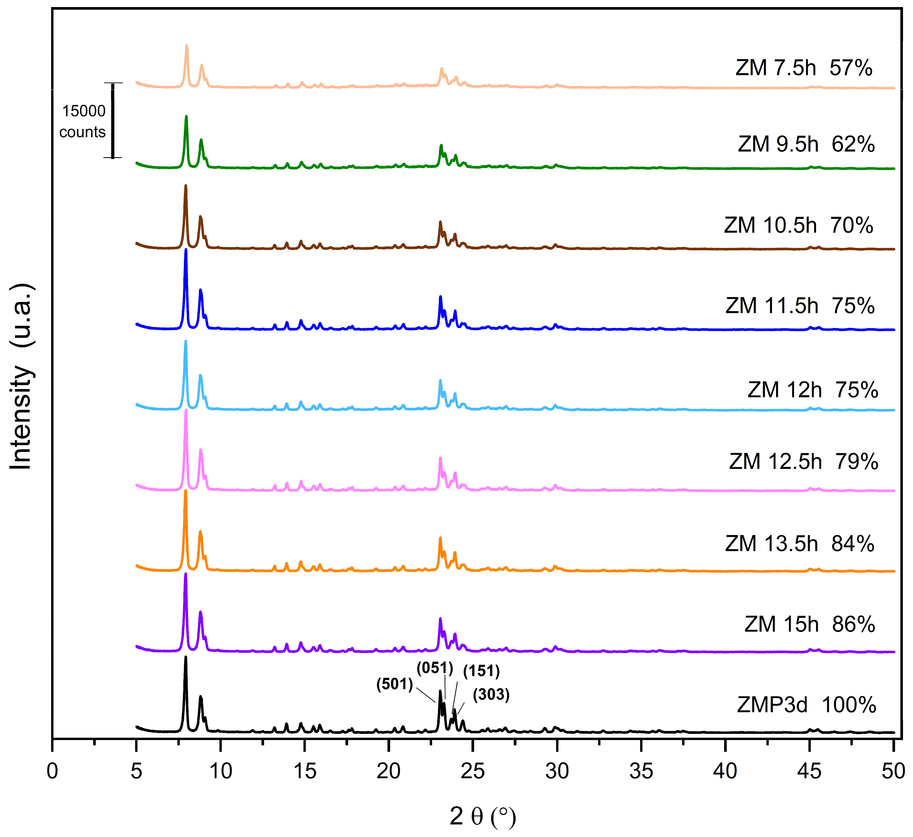
The X-ray diffractograms of the MFI-structured zeolites synthesized from Aerosil®200 and MPI silica at the studied crystallization times are shown in Figure 1. The standard used is the zeolite synthesized with commercial silica Aerosil®200. Zeolites synthesized with MPI silica were compared with this standard to calculate the relative crystallinity, considering the ZMP 3 d as 100%. It is observed that the synthesized materials are similar, confirming the crystal structure and characteristics of the MFI-structured zeolites. The reflections for calculating crystallinity were obtained in the 2θ range from 22.5 to 25°. The reflections correspond to the planes (501), (151), (051), and (303) in MFI-type structures [20,21,22].
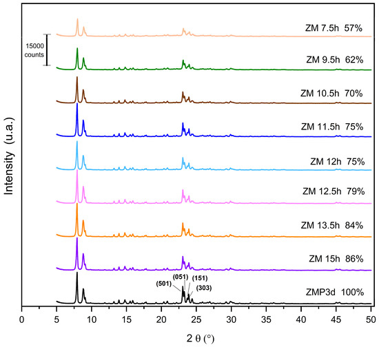
Figure 1.
X-ray diffractograms of zeolites with MFI structure in the basic medium with Aerosil®200 (ZMP) and MPI (ZM) silica with their respective relative crystallinities.
The results for the zeolites with MPI silica had lower crystallinity levels than ZMP 3 d, a characteristic behavior mainly when using natural materials. Thus, considering the optimization, the ideal synthesis condition in this work was 15 h, with a crystallinity of 86%. The crystallization time has an important influence on the synthesis of zeolites. Increasing synthesis time favors the formation of the MFI zeolite; however, in the long term, it will produce other undesirable crystalline phases [23]. Variations in the crystallinity of materials at high synthesis times may occur because some of the crystals present may undergo dissolution and recrystallization processes [24]. For the samples presented in Figure 1, we did not observe such an effect because we can see that the relative crystallinity increases linearly over time. The intensity of the peaks increases with the Si/Al ratio. This phenomenon is in accordance with a higher structural order due to the increasing number of equal Si-O-Si bonds in tetrahedral positions, thus decreasing the average length of the T-O-T bond [25].
The XRF data of the zeolites synthesized with Aerosil®200 silica (ZMP 3 d) and MPI (ZM) are presented in Table 4. The results indicate that the MFI-structured zeolites in the basic medium synthesized with MPI silica presented a similar composition to the main oxides obtained with ZMP 3 d, regardless of the crystallization time studied. The percentage variations would be associated with the characteristics of the alternative source of MPI silica.
Table 4.
XRF results of MFI-structured zeolites in the basic medium synthesized with Aerosil®200 silica and MPI at the main times studied, MPI silica, and Si/Al ratio.
The Si/Al molar ratios of ZM zeolites increase compared to zeolite with Aerosil®200 silica, and, with the increasing crystallization time, variations in the Si/Al ratio occurred. MPI silica has a high percentage of silicon in its composition, which implies a high Si/Al ratio, which makes it suitable for the synthesis of MFI-structured zeolites that have a high Si/Al ratio, ranging from 15 to infinity. In this work, this ratio varied from 30.18 to 38.78, which is in the range of results found in the literature, such as those reported by Sivalingam and Sen, (2020) [26], who obtained a Si/Al ratio of 32.24.
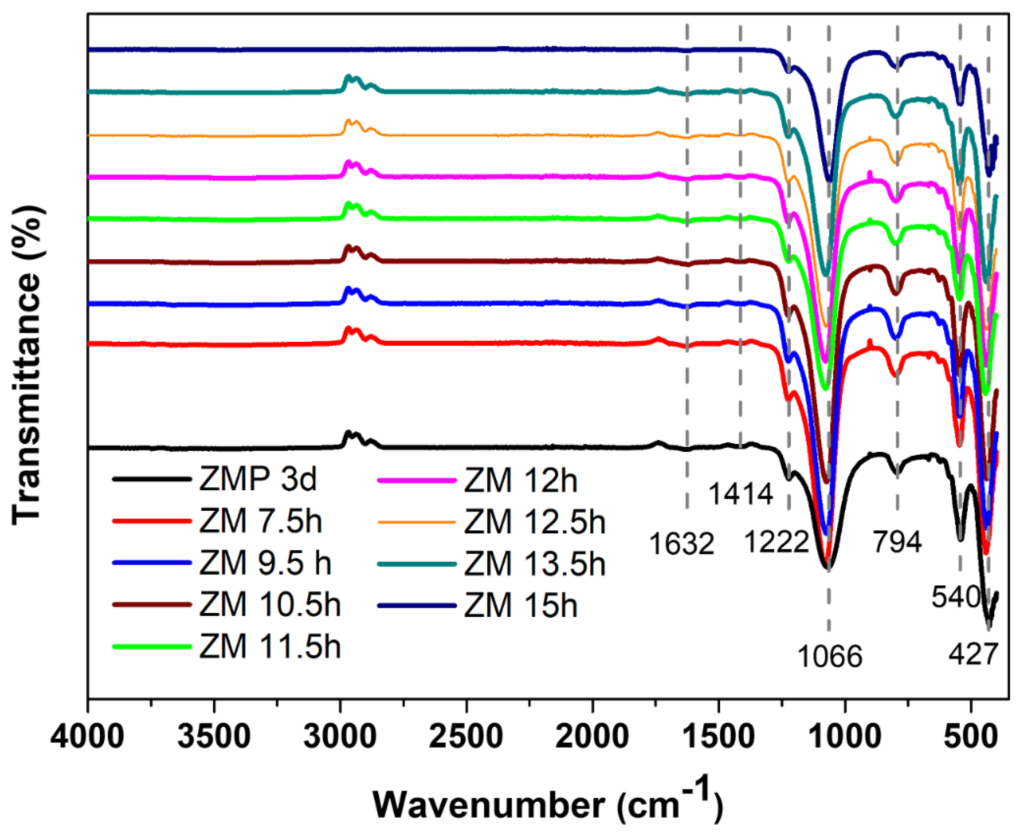
The main bands of MFI-structured zeolites in the basic medium sintered with Aerosil®200 silica (ZMP 3 d) and MPI (ZM) at the times studied were identified by FTIR, as can be seen in Figure 2. The band at 1632 cm−1 is attributed to the stretching of the water molecule that was absorbed on the surface of the zeolite structure. The band at 1222 cm−1 is related to the asymmetric bonds of siliceous materials in the T-O-T group of the TO4 tetrahedron. The bands at 1066 cm−1 and 794 cm−1 are attributed to the symmetric stretching of outer TOT bonds and the asymmetric stretching of inner TOT bonds, respectively. The band at 540 cm−1 represents the vibrations from the deformation of the TO bond of the internal tetrahedral of SiO4 and AlO4, and the vibrations at 427 cm−1 correspond to the asymmetric stretching of the two-membered rings (D5R) of the pentassyl structure of zeolites with an MFI structure and characteristics, which states the formation of its structure [27,28,29,30]. FTIR analysis thus suggests the successful formation of zeolites with MFI-type structures [31].
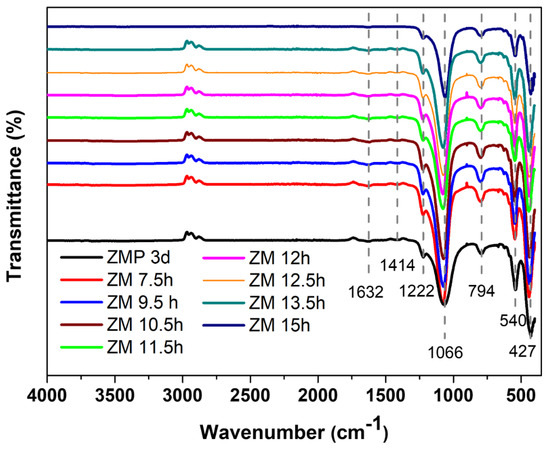
Figure 2.
FTIR spectrum of the main bands of zeolites with MFI structures in the basic medium with Aerosil®200 silica (ZMP 3 d) and MPI (ZM) at the times studied.
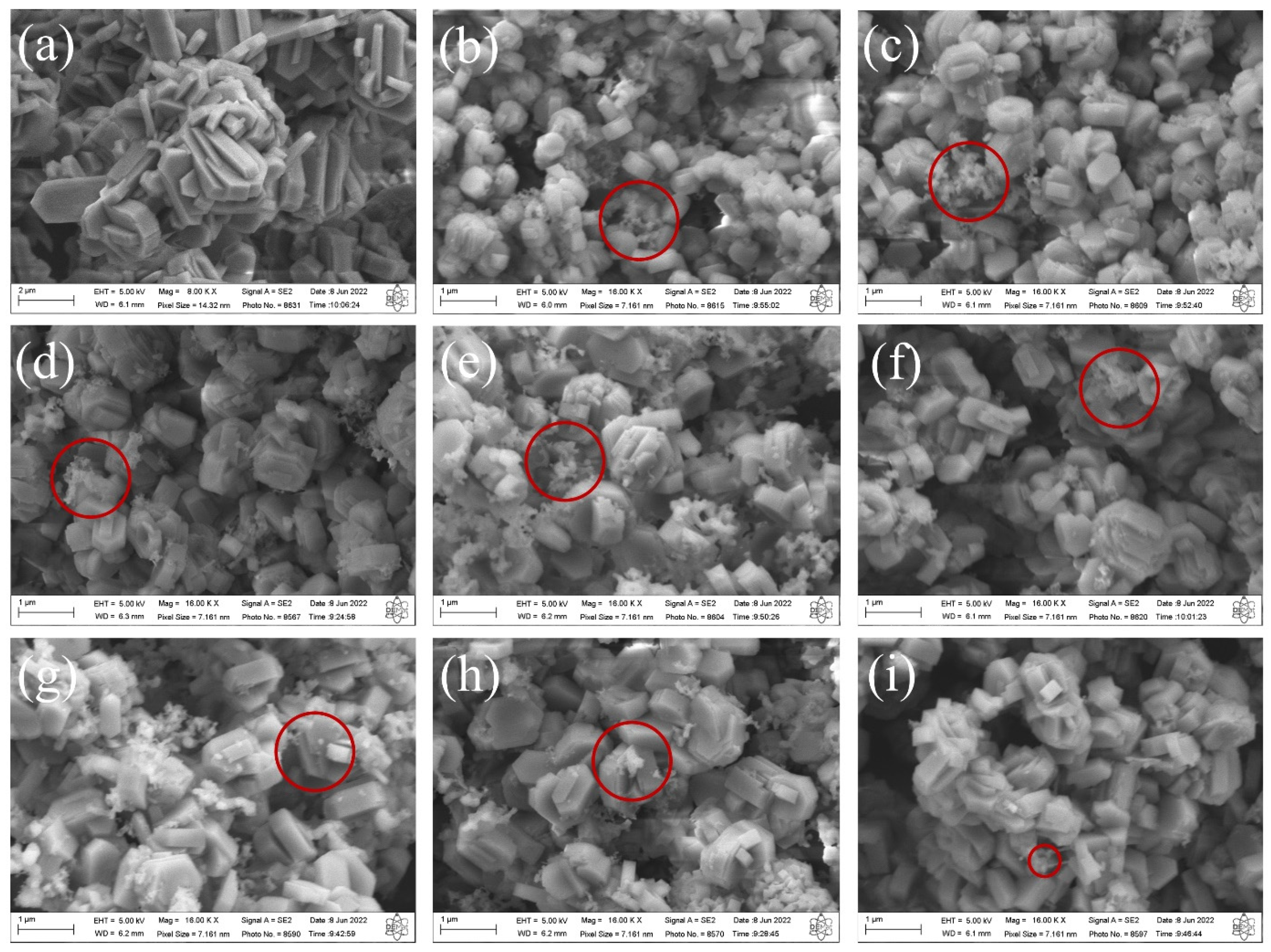
The SEM images of the synthesized MFI-structured zeolites in the basic medium are shown in Figure 3. The results indicate that the zeolite synthesized with Aerosi®200 (a) ZMP 3 d silica exhibits agglomerated hexagonal clintheriform crystals with miscellaneous particle size distribution. The zeolites obtained from MPI silica at the times studied, namely (b) ZM 7.5 h, (c) ZM 9.5 h, (d) ZM 10.5 h, (e) ZM 11.5 h, (f) ZM 12 h, (g) ZM 12.5 h, and (i) ZM 15 h, also exhibit crystals with agglomerated hexagonal clintheriform morphology with varying size distributions, being smaller than those synthesized with Aerosil®200 silica [24,32]. Furthermore, it is possible to see clusters of amorphous silica (images highlighted in red micrographs of Figure 3) with an irregular distribution that probably did not react during the synthesis or are the result of the dissolution of the tetrahedra of the zeolitic structure. The particle size does not change significantly with the extension of the crystallization time.
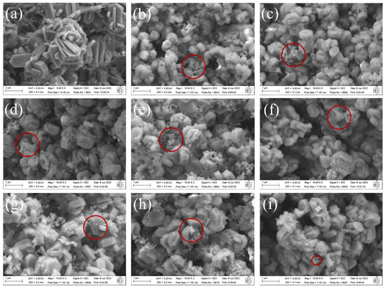
Figure 3.
SEM images of MFI-structured zeolites in the basic medium (a) Aerosil®200 silica (ZMP 3 d) and MPI silica at different times: (b) ZM 7.5 h, (c) ZM 9.5 h, (d) ZM 10.5 h, (e) ZM 11.5 h, (f) ZM 12 h, (g) ZM 12.5 h, (h) ZM 13.5 h, and (i) ZM 15 h. Red circles indicate regions with the presence of clusters of amorphous silica.
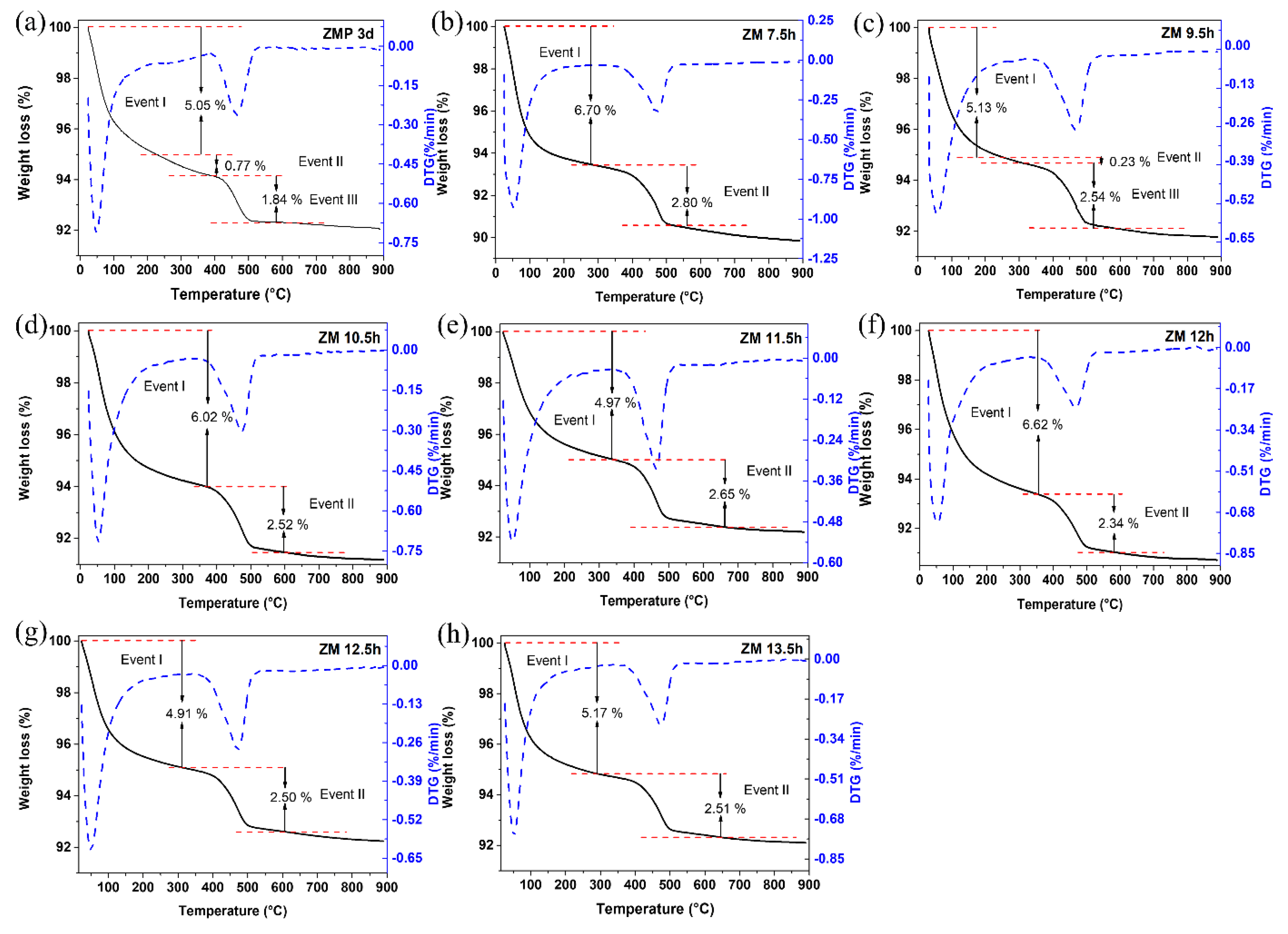
The results of the thermogravimetric and differential thermal curves of MFI-structured zeolites in the basic medium are presented in Figure 4, (a) with Aerosil®200 silica (ZMP 3 d) and with MPI silica, at different times, namely (b) ZM 7.5 h, (c) ZM 9.5 h, (d) ZM 10.5 h, (e) ZM 11.5 h, (f) ZM 12 h, and at times (g) ZM 12.5 h and (h) ZM 13.5 h. Two or three mass loss events can be observed in the gravimetric curves, which vary according to the synthesis time. For ZMP 3 d, we have the first event that occurs in the range of approximately 25 °C to 229 °C with a mass loss of 5.05%, corresponding to the desorption of H2O. The second event is in the range of approximately 229 °C to 378 °C, with a mass loss of 0.77%, and the third event is in the range of 378 °C to 526 °C, with a mass loss of 1.84%, corresponding to the degradation of the organic director TPABr [27]. Zeolites synthesized with MPI silica present similar events and mass losses to zeolites with Aerosil®200 silica. These results indicate that calcination at 550 °C can eliminate TPABr from zeolites with an MFI structure [33].
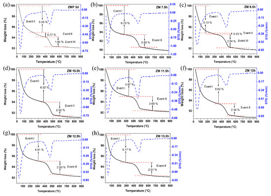
Figure 4.
TG/DTG thermal analysis of MFI-structured zeolites in the basic medium (a) Aerosil®200 silica (ZMP 3 d) and MPI silica at different times: (b) ZM 7.5 h, (c) ZM 9.5 h, (d) ZM 10.5 h, (e) ZM 11.5 h, (f) ZM 12 h, (g) ZM 12.5 h, and (h) ZM 13.5 h.
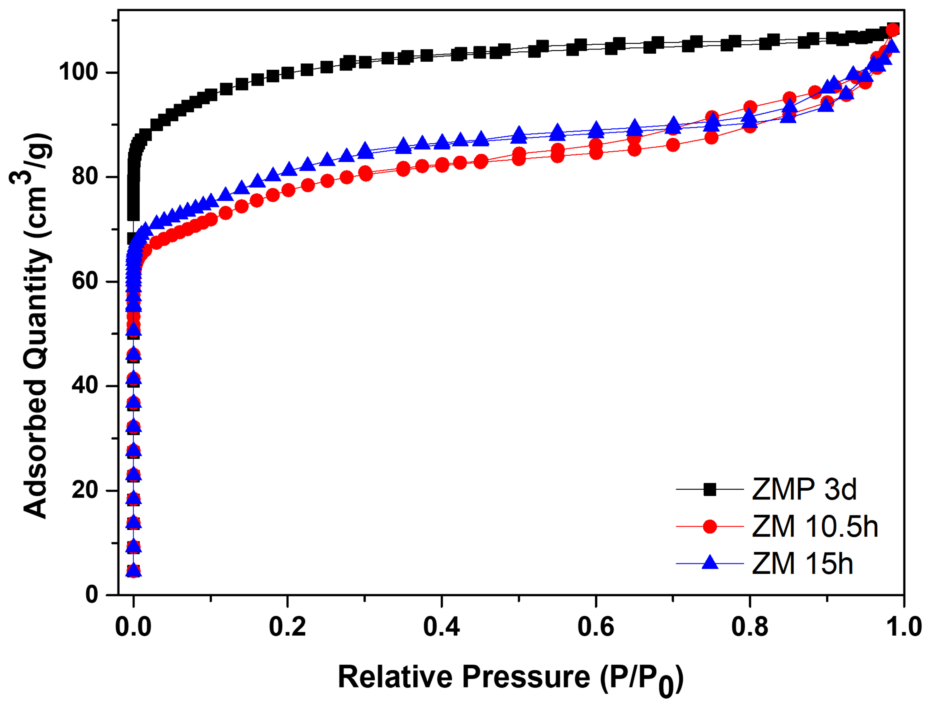
Figure 5 shows the N2 adsorption/desorption isotherms for the zeolite with Aerosil®200 silica, ZMP 3 d, and those synthesized with MPI silica, ZM 10.5 h and ZM 15 h. Table 5 contains the textural parameters. The results show that the isotherms of the materials are a combination of type I and II that have micropore characteristics and a contribution of the external area and volume between particles (typical of porous or macroporous materials) [34,35,36,37]. Furthermore, the intercrystalline pores of zeolites can be formed through aggregates of nanometric zeolitic crystals. The intercrystalline mesopores may be formed via the aggregation of nanosized zeolite crystals [38]. Another characteristic present in the isotherms is high N2 adsorption at relatively low pressures, which can be attributed to the intrinsic micropores of the zeolites [39].
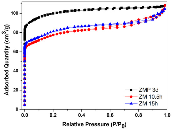
Figure 5.
N2 adsorption/desorption isotherms for MFI-structured zeolites in the basic medium with Aerosil®200 silica (ZMP 3 d) and MPI, ZM 10.5 h, and ZM 15 h.
Table 5.
Textural properties of MFI-structured zeolites in the basic medium with Aerosil®200 silica and MPI.
The zeolite with Aerosil®200 silica has a larger area of 380 m2/g, a total volume of 0.168 cm3/g, and micropores of 0.119 cm3/g, which are larger than zeolites from MPI silica but have a smaller average pore diameter. The modification with silica directed the formation of mesopores, consequently causing a smaller micropore volume. The total pore volume remained almost constant, indicating that the modification did not change this parameter [40]. Usually, when the crystallization of the zeolite exceeds the aging stage and enters the crystallized stage, the value of the specific micropore area is directly related to the crystallinity; this would be the reason for the more significant number of micropores of the ZMP 3 d zeolite, followed by the ZM 15 h zeolite [41]. Comparing the zeolites from MPI silica, ZM 15 h had more significant textural parameters, except for the total pore volume, but was approximately the same. Therefore, these results of the textural parameters are consistent with the results obtained from the calculated crystallinity and phases observed in the XRD. The materials with higher percentages of more crystallinity present higher textural parameters.
3.2. Characterizations of MFI-Structured Zeolites in Hydrofluoric Medium
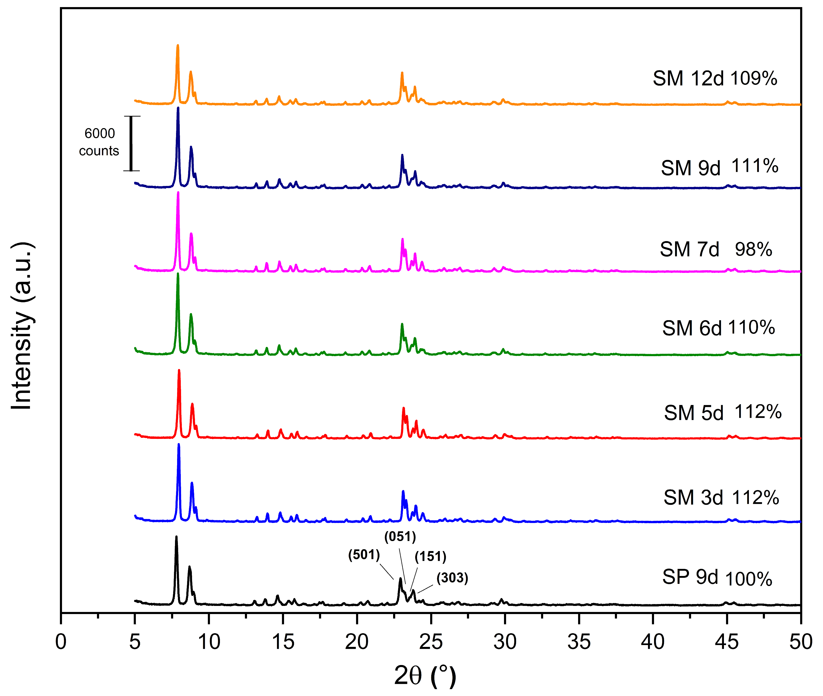
The X-ray diffractograms of the MFI-structured zeolites synthesized from Aerosil®200 and MPI silica are shown in Figure 6, as well as the relative crystallinity, with SP 9 d taken as 100%. All the synthesized zeolites have the following reflections: 2θ = 7.80°, 8.86°, 14.64°, 22.93°, 23.79°, and 24.18°, which include the hkl planes (011), (200), (051), (501), (033), and (313), respectively, of the pentasil structure of MFI-type zeolites [21,24,41,42].

Figure 6.
X-ray diffractogram for the MFI zeolites, silicalite with Aerosil®200 silica (SP 9 d), and MPI in the hydrofluoric medium with MPI silica (SM) at the crystallization times studied.
The results of the XRD patterns (Figure 6) indicate that most of the zeolites with MPI silica had a higher relative crystallinity than SP 9 d, with the best result for the SM 5 d zeolite, which occurs mainly when natural zeolites are used. Considering the optimization of the synthesis parameters, the ideal condition was 3 days with a relative crystallinity of 112%. Over the synthesis time, there was an increase and decrease in crystallinity, probably due to the dissolution and crystallization of the crystals [23]. This behavior was similar to the synthesis of zeolites with MFI structures in the basic medium.
The XRF analysis of silicalite with Aerosil®200 silica (SP 9d) and zeolites with MFI structure in the hydrofluoric medium from MPI silica (SM) at the studied times are presented in Table 6. The results indicate that the zeolites synthesized with MPI silica have compositional variations regarding those synthesized with standard silica, regardless of the crystallization time studied, but with a high percentage of silicon. The percentage variations would be associated with the characteristics of the alternative source of MPI silica. The Si/Al molar ratios of zeolites with MPI silica have higher average values than those in the basic medium.
Table 6.
XRF results of silicalite synthesized with standard silica and MPI in the hydrofluoric medium at the main times studied, MPI silica, and Si/Al ratio.
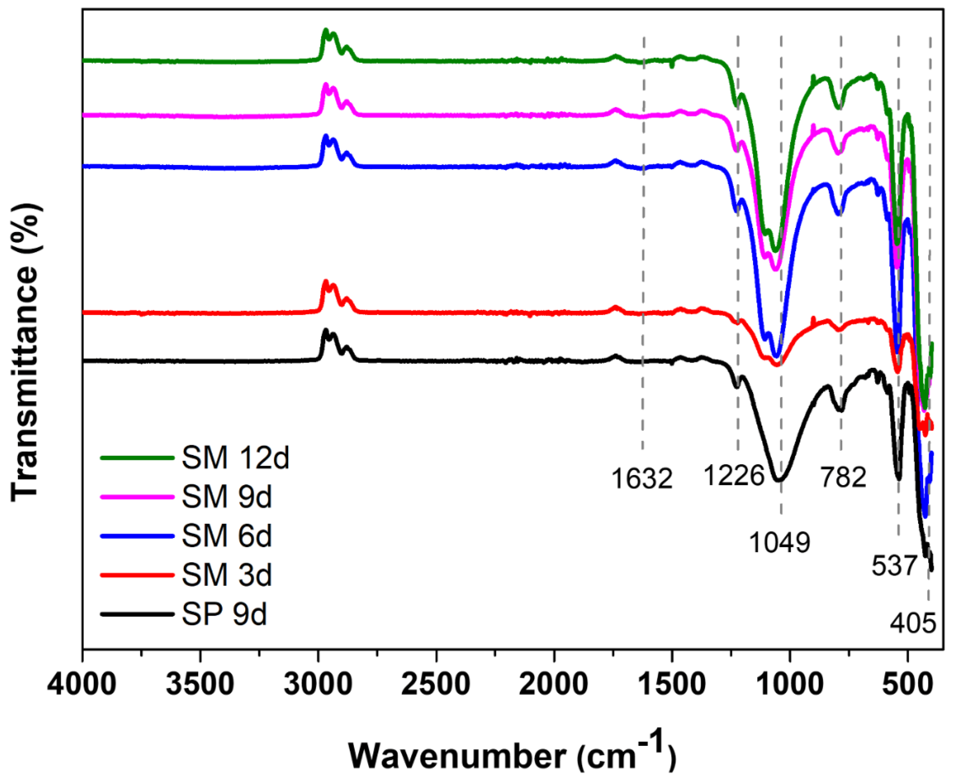
The main groups of the silicalite synthesized with Aerosil®200 silica (SP 9 d) and zeolites with MFI structures in the hydrofluoric medium from MPI silica (SM) were identified by FTIR, as can be seen in Figure 7. The band at 1632 cm−1 refers to the -OH bond of the water absorbed on the zeolite surface. The band at 1226 cm−1 is attributed to the asymmetric stretching of the Si-O-Si bond of the external SiO4 tetrahedron. The band at 1049 cm−1 arises from the asymmetric stretching of the Si–O–Si bond of the internal SiO4 tetrahedron. The band at 782 cm−1 refers to the symmetric stretching of the Si–O–Si bond of the external SiO4 tetrahedron. The band at 537 cm−1 is attributed to the vibration of the double five ring (D5R) and is characteristic of the pentasil structure of MFI-structured zeolites in the hydrofluoric medium. The intensity of this band is useful to evaluate the stability and crystallinity of the obtained samples. Similar intensities suggest that the zeolites are similar in structure, stability, and crystallinity. The band at 405 cm−1 refers to the vibration of the Si-O-Si bond [43,44,45,46,47].
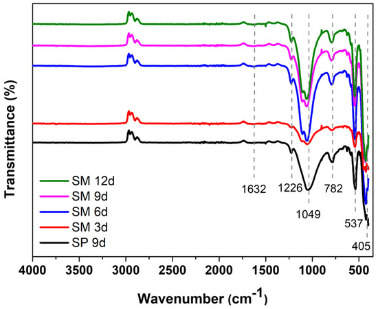
Figure 7.
FTIR spectrum of the main bands of silicalite with Aerosil®200 silica (SP 9 d) and MPI (SM) at different times.
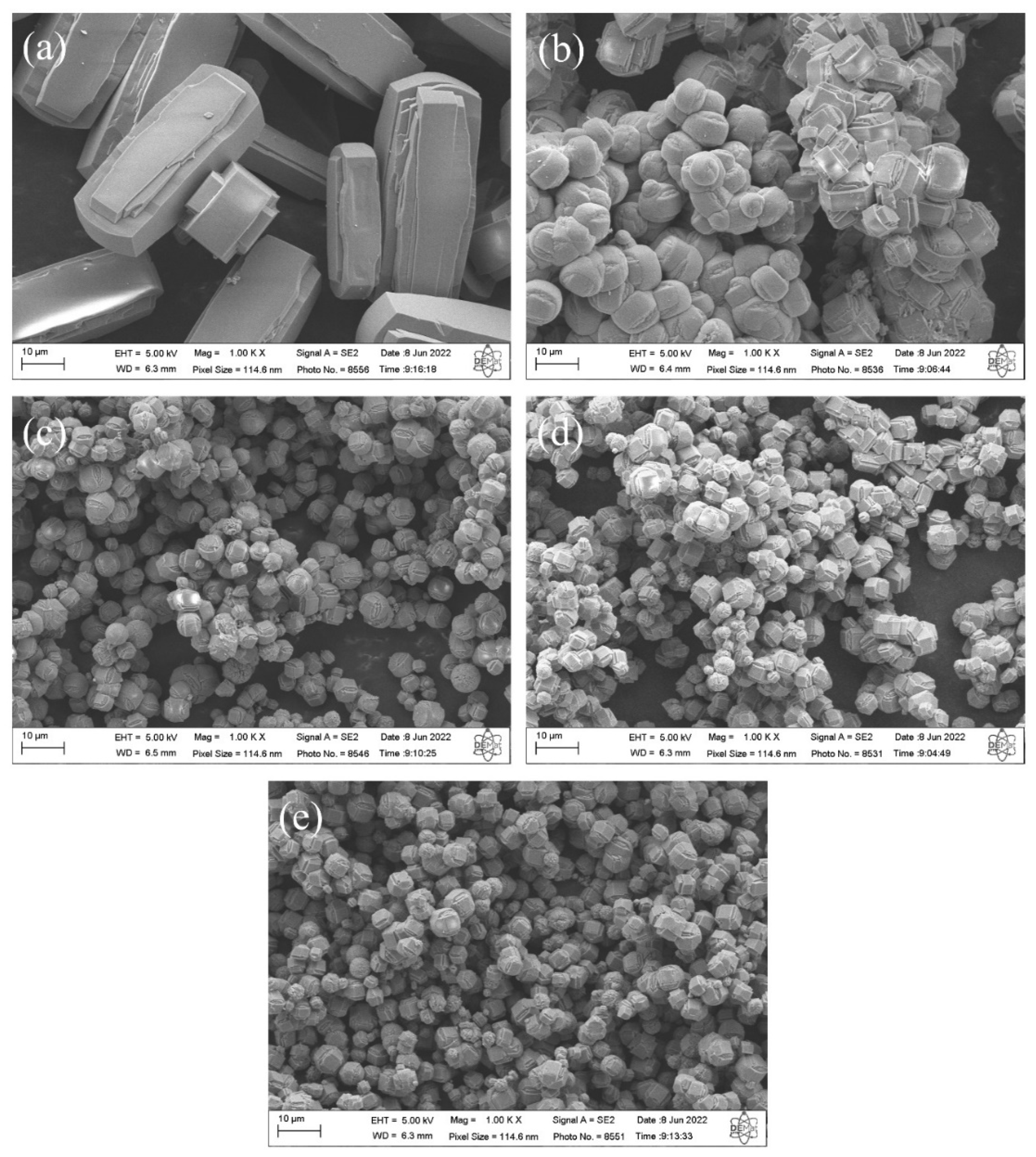
The SEM micrographs of silicalites synthesized with Aerosil®200 silica (SP 9 d) and zeolites with MFI structures in the hydrofluoric medium from MPI silica (SM) are shown in Figure 8. The results indicate that the zeolite (a) SP 9 d exhibits hexagonal elongated prismatic crystals [10]. The zeolites with MFI structures with MPI silica at the studied times, namely (b) SM 3 d, (c) SM 6 d, (d) SM 9 d, and (e) SM 12 d, also exhibit crystals with a hexagonal prismatic morphology, but that are generally more rounded, that agglomerated with a varied size distribution, that have smaller particles than those synthesized with standard silica, and that have larger particles than those in the basic medium with MPI silica. A possible explanation for the morphological changes in MFI-type zeolites includes the characteristics of MPI silica, which also contain other elements in their composition, such as aluminum, and may have led to the formation of morphological characteristics more similar to those in the basic medium.

Figure 8.
SEM images of silicalite (a) with Aerosil®200 silica (SP 9 d) and zeolites with MFI structure in the hydrofluoric medium with MPI silica at different times: (b) SM 3 d, (c) SM 6 d, (d) SM 9 d, and (e) SM 12 d.
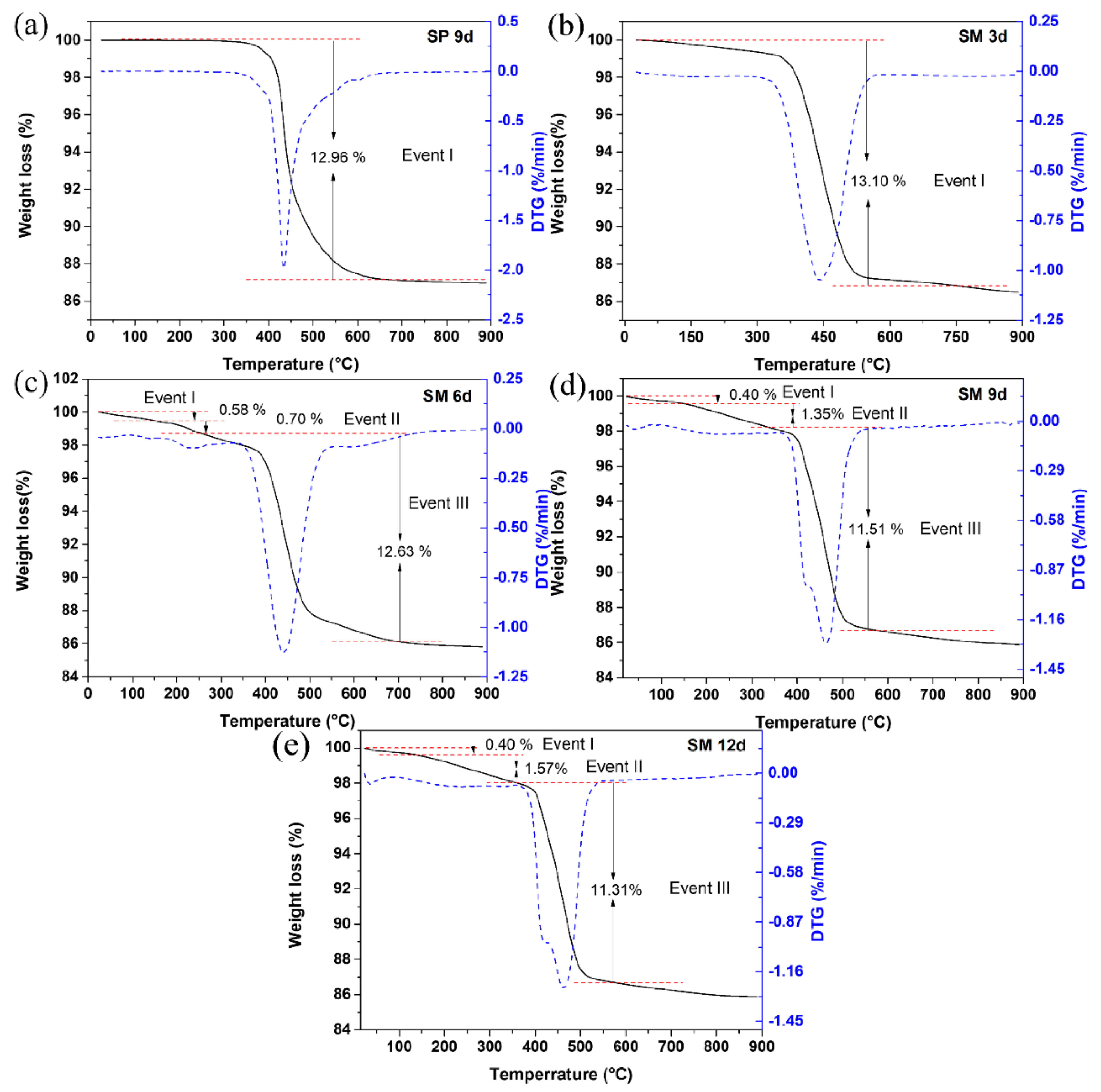
The differential thermogravimetric and thermal curves of silicalite (a) SP 9 d and zeolites with MFI structures in the hydrofluoric medium with MPI silica at different times, namely (b) SM 3 d, (c) SM 6 d, (d) SM 9 d and (e) SM 12 d, are shown in Figure 9. Most zeolites have from one to up to three mass loss events. The results indicate an event in the range approximately from 288 °C to 639 °C with a mass loss of 12.81% that corresponds to the decomposition and combustion of the organic template TPAOH and the losses of fluoride. Some zeolites synthesized with MPI silica (SM 6 d, SM 9 d, and SM 12 d) presented a first event in the range of 25 °C to 155 °C with a mass loss in the range of 0.4% to 0.58% and an event in the range of 155 °C to 247 °C with a mass loss in the range of 0.7% to 1.57%, which can be attributed to the loss of free water and water present in the zeolitic structure, respectively [10,28,33].
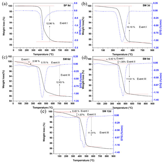
Figure 9.
Thermal TG/DTG analysis of silicalite (a) with Aerosil®200 silica (SP 9 d) and MFI-structured zeolites in the hydrofluoric medium with MPI silica at different times: (b) SM 3 d, (c) SM 6 d, (d) SM 9 d, and (e) SM 12 d.
Figure 10 contains the N2 adsorption/desorption isotherms for silicalite with Aerosil®200 silica, SP 9 d, and MFI-structured zeolites in the hydrofluoric medium from MPI silica, namely SM 3 d and SM 6 d, and Table 7 presents the textural parameters. The results show that the isotherms of the synthesized zeolites present a combination of type I and IV isotherms, which present narrow steps that are indicative of the microporous nature and capillary condensation of N2 in the primary mesopores, possibly derived from the crystal grain boundaries [48,49,50,51].
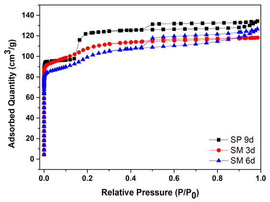
Figure 10.
N2 adsorption/desorption isotherms for silicalite with Aerosil®200 silica (SP 9 d) and MFI-structured zeolites in the hydrofluoric medium (SM) with MPI silica at different times.
Table 7.
Textural properties of Aerosil®200 silicalite with MFI structures in the hydrofluoric medium, synthesized from MPI silica.
The SP 9 d zeolite has a larger area of 407 m2/g, a total pore volume of 0.208 cm3/g, a micropore volume of 0.166 cm3/g, and an average pore diameter of 0.467 nm, which are larger compared to zeolites with MPI silica. The modification with silica, as well as those synthesized in the basic medium, led to lower mesopore formation and micropore volume. The different crystallinity values, as observed in the MFI-structured zeolite in the basic medium, may have influenced the variations in the textural parameters. Comparing the MFI-type zeolites with MPI silica, SM 3 d had a larger area and average pore diameter than SM 6 d, but had a smaller total pore volume. This variation may be related to the time variation that implies the change in the textural parameters [41].
From the characterization results, the materials synthesized with MPI silica have similar characteristics, so the main results will be used.
3.3. Application of Zeolitic Materials in CO2 Capture
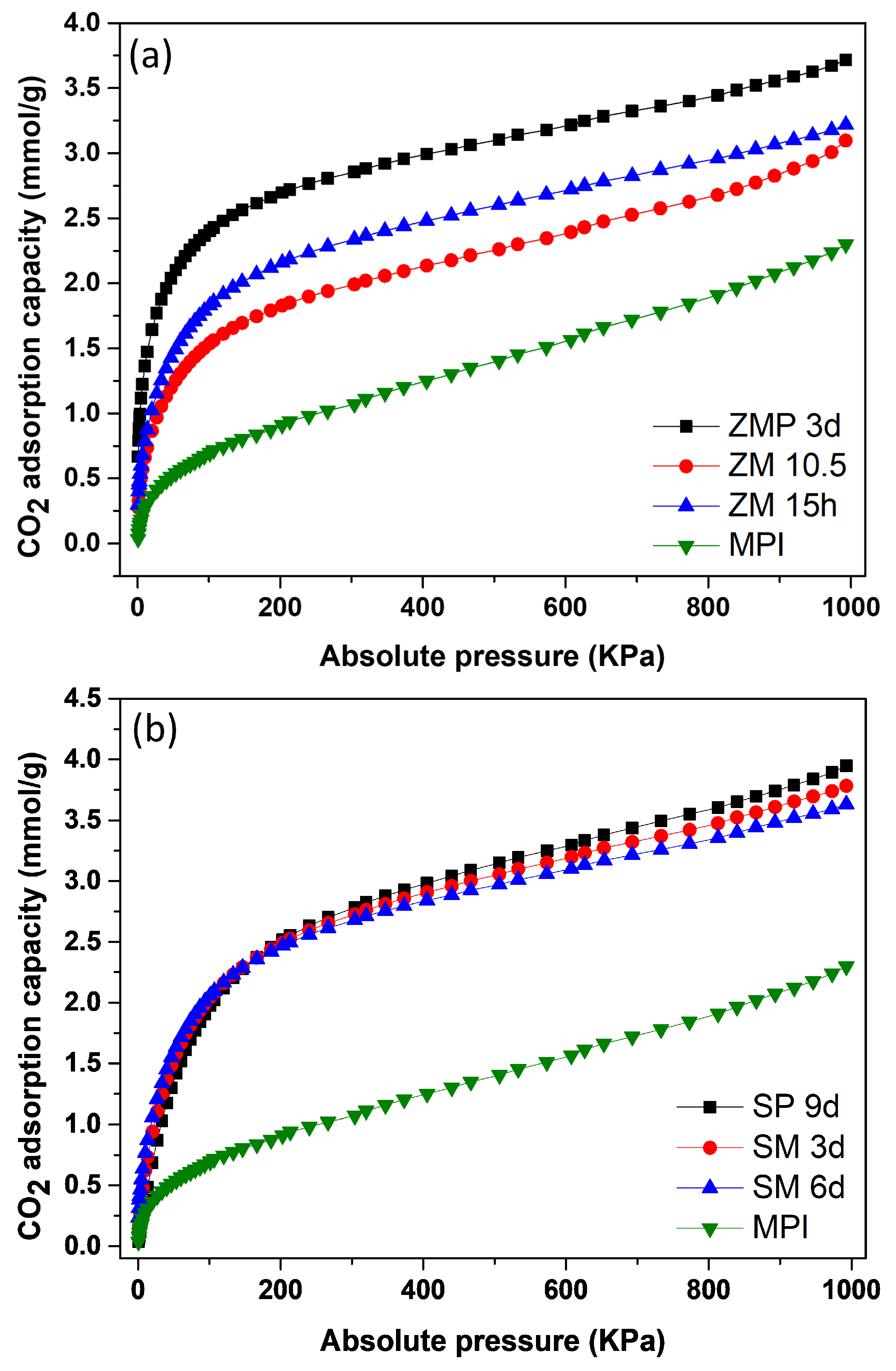
Figure 11a shows the isotherms for the MFI-structured zeolite with Aerosil®200 silica and MPI silica. The results indicate that ZMP 3 d obtained an adsorption level of 3.72 mmol/g of CO2, which was higher compared to ZM 15 h, with 3.22 mmol/g of CO2 and ZM 10.5 h, with 3.10 mmol/g of CO2. Figure 11b contains isotherms for silicalite and the MFI-structured zeolites from MPI silica. The SP 9 d zeolite had an adsorption level of 3.94 mmol/g of CO2, which was higher compared to zeolites SM 3 d, with 3.78 mmol/g of CO2 and SM 6 d, with 3.60 mmol/g of CO2. The starting material, MPI silica, showed the lowest adsorption capacity of 2.29 mmol/g CO2, indicating the advantage of using zeolites for CO2 adsorption. All adsorption curves showed type I isotherms, according to the IUPAC classification [52,53].
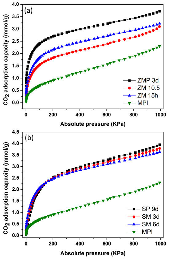
Figure 11.
CO2 isotherms: (a) zeolite with MFI structure in basic Aerosil®200 (ZPM) and MPI (SM) media and in hydrofluoric media; (b) silicalite (SP) and zeolites of the MFI type (SM) and silica MPI.
In the Supplementary Materials, Tables S1 and S2 show the results obtained regarding the CO2 adsorption capacity of materials at low pressures of up to 20 KPa and the maximum pressure reached, 1000 kPa, at a temperature of 23 °C.
Table 8 shows some of the materials in the literature used for CO2 capture with their respective adsorptive capacities. Some of the results found are inferior, similar, or better compared to those obtained in this work. On the other hand, this work uses a low-cost source that causes modifications in the characteristics of the studied zeolites, as observed in the morphology, which can be explored and modified to improve the CO2 adsorptive capacity of these materials.
Table 8.
Works found in the literature used in CO2 capture.
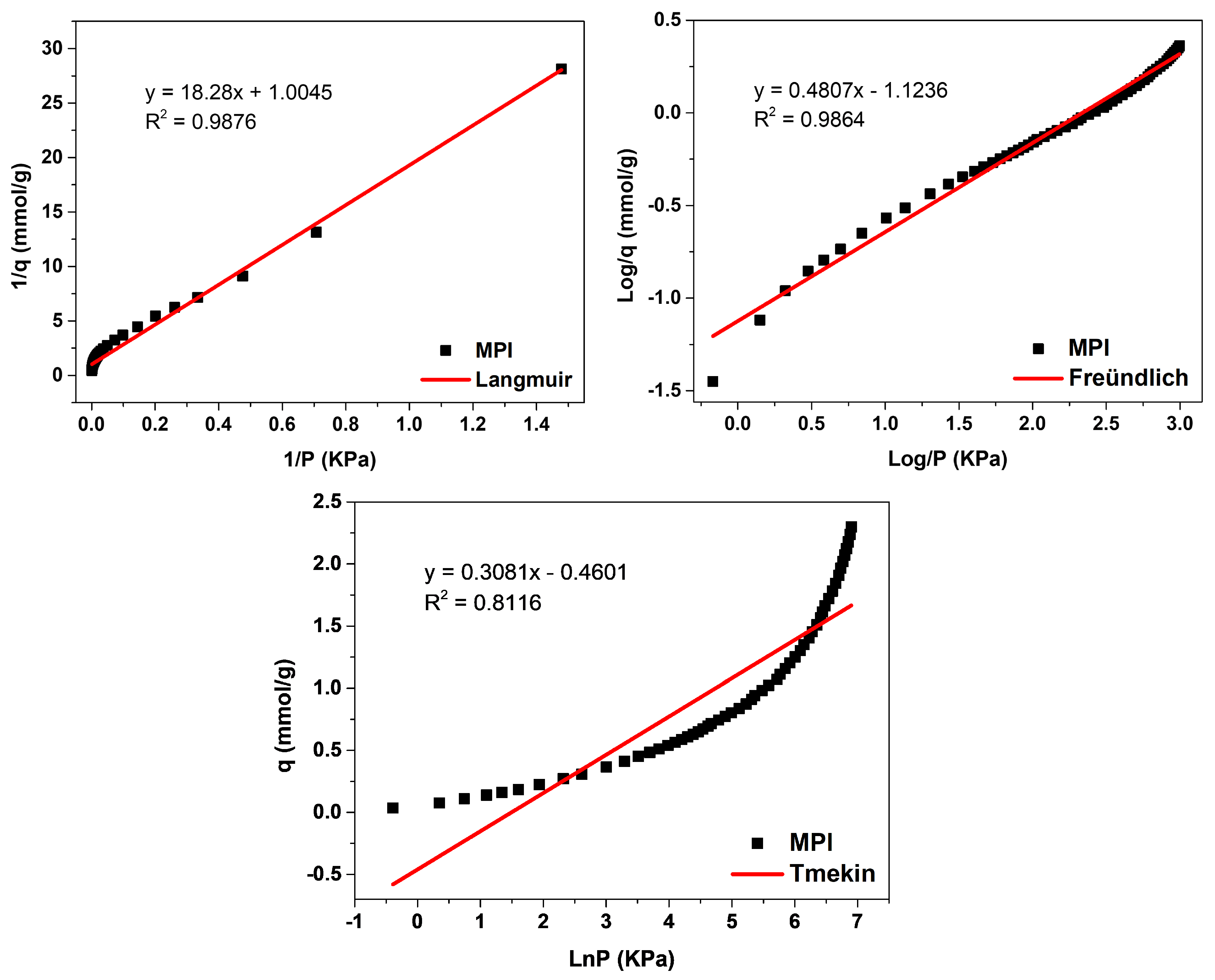
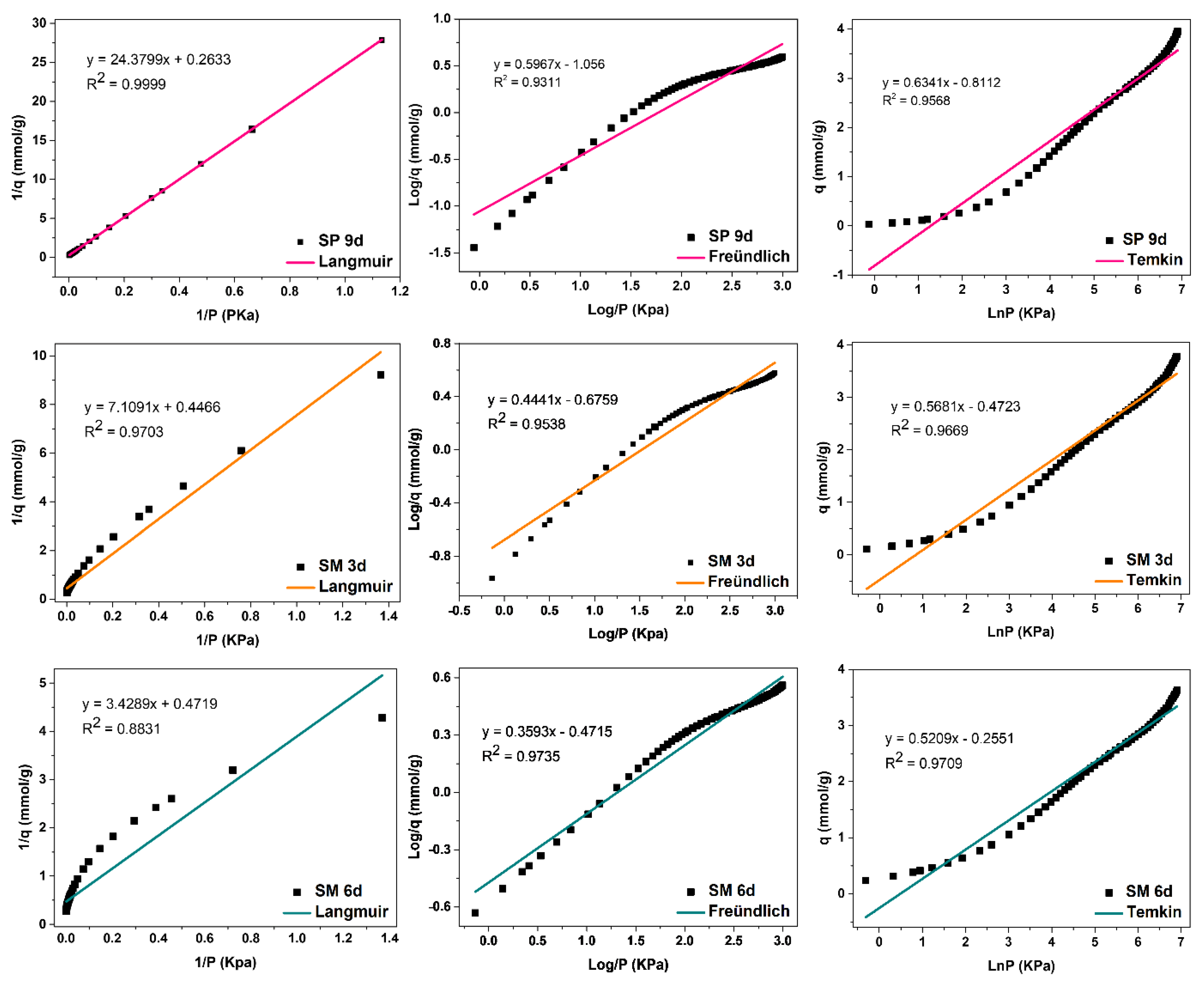
The evaluation of the adsorption mechanisms involving the adsorbent and adsorbate was obtained from the adjustments of the Langmuir, Freündlich, and Temkin linear mathematical models, shown in Figure 12, Figure 13 and Figure 14. Table 9 presents the parameters obtained. The results indicate that the highest adsorptive capacities of each type of adsorbent (qm) were for those synthesized with Aerosil®200 silica 2.56 mmol/g CO2 (ZMP 3 d) and 3.79 mmol/g CO2 (SP 9 d). Regarding those synthesized with MPI silica, the best result was for SM 3 d, with a capacity of 2.23 mmol/g CO2 and ZM 15 h, with a capacity of 1.87 mmol/g CO2. MPI silica had the lowest adsorption capacity, with 0.99 mmol/g CO2. All synthesized materials have the separation factor RL between 0 and 1, indicating that they are favorable to CO2 adsorptive processes.
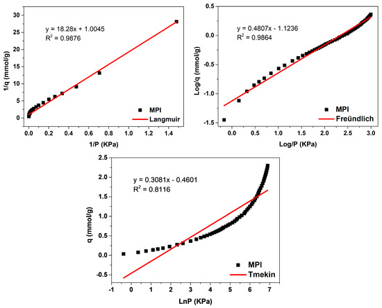
Figure 12.
Fits of the linear mathematical models of Langmuir, Freündlich, and Temkin for MPI silica.
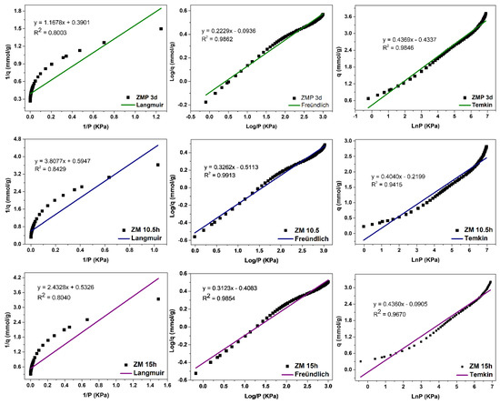
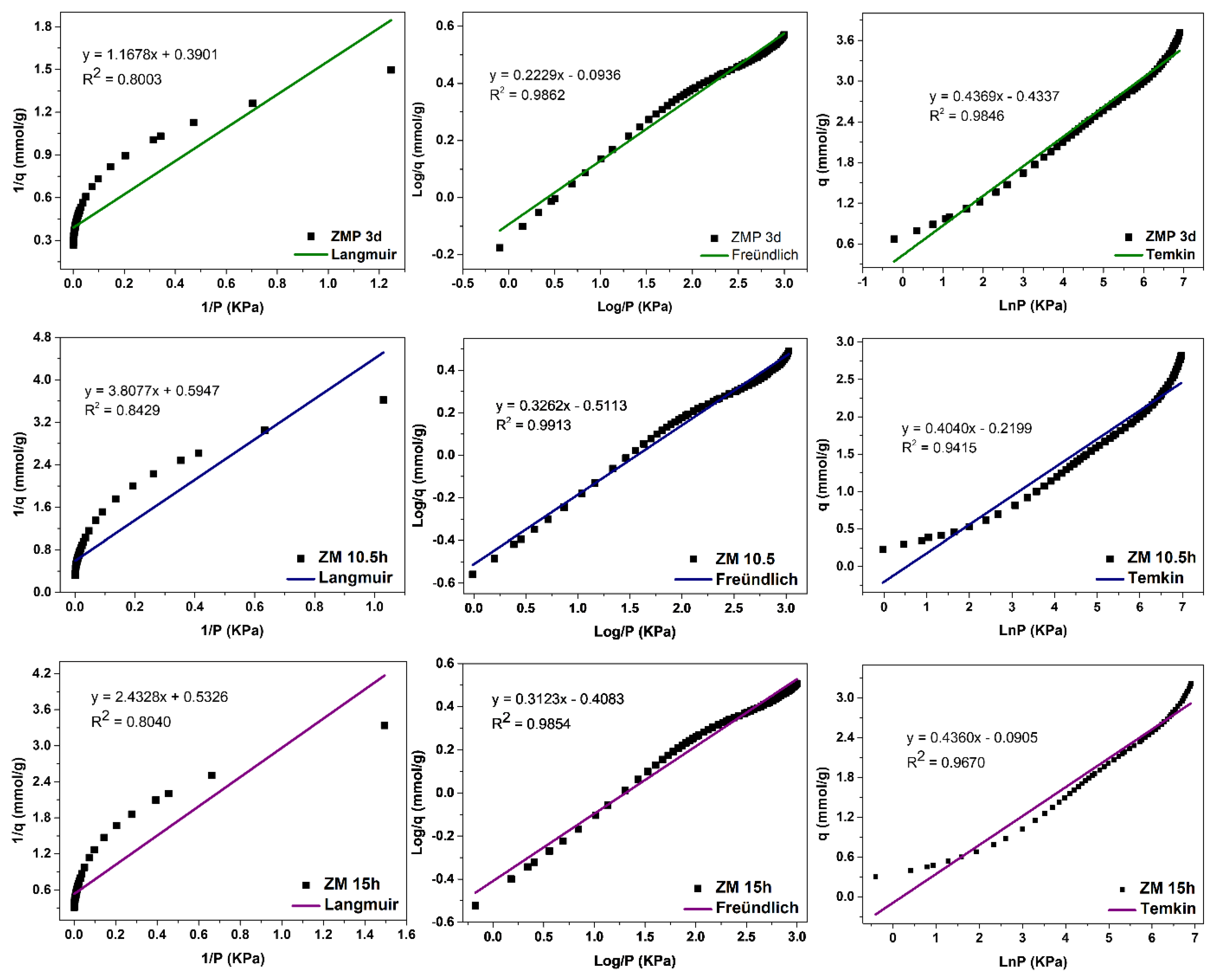
Figure 13.
Fits of the Langmuir, Freündlich, and Temkin linear mathematical models for MPI silica and MFI zeolites with Aerosil®200 (ZMP) and MPI (ZM) silica in the basic medium.
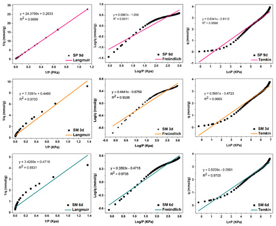
Figure 14.
Fits of the Langmuir, Freündlich, and Temkin linear mathematical models for MPI silica and MFI zeolites with Aerosil®200 (SP) and MPI (SPM) silica in hydrofluoric medium.
Table 9.
Parameters and coefficients of the determination of the Langmuir, Freündlich, and Temkin isothermal mathematical models for MPI silica and MFI-structured zeolites.
MPI silica, Figure 12, obtained the best fit for the Langmuir model, with a correlation coefficient of R2 = 0.9876, meaning that the predominant adsorption mechanism has a homogeneous distribution on the surface. Monolayer adsorption contributes to a restricted amount of adsorbent sites that are energetically equivalent. Furthermore, there is no interaction between the adsorbed molecules [12,13]. The Freündlich model was the second-best fit, with a correction coefficient of R2 = 0.9864, higher KF values indicate a greater affinity for an adsorbate and a specific temperature. The value of 1/n was greater than 0 and less than 1 (0 < 1/n < 1), indicating that the adsorptive process involved is favorable, which is in agreement with the results of the separation factor RL [17,18]. The MPI silica did not fit the Temkin model, with a coefficient of R2 = 0.8116
The MFI-structured zeolites in the basic medium, Figure 13, had the best fit to the Freündlich model, with R2 = 0.9862, R2 = 0.9913, and R2 = 0.9854 for ZMP 3 d, ZM 10.5 h, and ZM 15 h, respectively, indicating that the predominant mechanism is the adsorption on the heterogeneous surface of the adsorbent through multilayers [14]. The value of 1/n was greater than 0 and less than 1, indicating that the adsorptive process involved is favorable. Higher KF values indicate a greater affinity for an adsorbate at a specific temperature. These zeolites showed a good fit to the Temkin model, with the correlation coefficients R2 = 0.9846, R2 = 0.9415, and R2 = 0.9670, respectively, indicating that a physical nature acts in the adsorption process. The value of the Temkin constant (BT) was also lower than 8000 Kj·mmol−1, indicating that there is a contribution of physical nature in the adsorptive process. The Langmuir model did not fit the zeolites ZMP 3 d, ZM 10.5 h, and ZM 15 h, with coefficients of R2 = 0.8003, R2 = 0.8429, and R2 = 0.8040, respectively.
Silicalite SP 9 d and zeolites with MFI structures in the hydrofluoric medium with MPI silica SM 3 d, Figure 14, obtained the best fit for the Langmuir model, with correlation coefficients of R2 = 0.9999 and R2 = 0.9703, respectively. This indicates that the predominant adsorption mechanism presents a homogeneous distribution across the surface, with a monolayer formation in a restricted number of adsorbent sites that are energetically equivalent. Furthermore, there is no interaction between the adsorbed molecules [12,13]. The Temkin model also had a good fit for these zeolites with the coefficients R2 = 0.9568 and R2 = 0.9669, respectively, indicating the contribution of the physisorption process in the adsorption mechanism, since the value of the Temkin constant (BT) was also less than 8000 Kj·mmol−1. For Freündlich, the value of 1/n was greater than 0 and less than 1, indicating that the adsorption process is favorable [18].
The SM 6 d zeolite, Figure 14, had the best fit for the Temkin model, with a coefficient of R2 = 0.9753, indicating that the predominant adsorptive mechanism is physical adsorption [15]. The second-best fit was for the Freündlich model, with R2 = 0.9735, indicating a greater contribution of the monolayer and multilayer in the adsorptive process. Furthermore, n values greater than 1 indicate that adsorption is favorable. The Langmuir model did not fit the experimental data for this material, with a coefficient R2 = 0.8831 [12,18].
4. Conclusions
MPI silica obtained from beach sand was successfully used in the eco-friendly synthesis of zeolitic materials with MFI structures, being applied in CO2 capture.
The MFI-structured zeolites in the basic medium synthesized from MPI silica have pure and crystalline phases, with the best synthesis time for ZM 15 h with a relative crystallinity of 92.90%. Zeolites have a similar chemical composition with the main elements, Si, Al, and Na, in their structure that is similar to ZMP 3 d, with variations in other elements due to MPI silica. The zeolites with MPI silica have higher silicon–aluminum ratios than ZMP 3 d, but are consistent with values found in the literature. The FTIR results showed that zeolites have the characteristic bands of the MFI structure. The SEM analyses indicate that the zeolites have agglomerated hexagonal clintform morphology with a varied particle size distribution. Zeolites from MPI silica have smaller particle sizes than ZMP 3 d, and this can be associated with the characteristics of the silicon source. The TG/DTG results indicate the good thermal stability of the molecular sieves. The textural parameters were characteristic of zeolites with MFI structures, with a larger specific area for ZMP 3 d, at 380 m2/g.
The MFI-type zeolites in the hydrofluoric medium synthesized with MPI silica have pure and crystalline phases, with the best results for the SM 3 d zeolite with a relative crystallinity of 111.90% about SP 9 d. The zeolites from MPI silica have a different chemical composition from SP 9 d due to the presence of elements from MPI silica, mainly Al and Na. The Si/Al molar ratios are, on average, higher than the MFI-type zeolites in the basic medium. The FTIR analyses indicate that the zeolites contain all the characteristic bands of MFI-type zeolites. The SEM results show that the MFI-type zeolites have the characteristic morphology of hexagonal primes much smaller than the SP 9 d zeolite. A possible explanation for the morphological changes is probably the characteristics of the silicon source, which also contained other elements in its composition, such as aluminum, and may have led to the formation of morphological characteristics more similar to those synthesized in the basic medium. The largest specific area was for silicalite, at 407 m2/g.
The results of the adsorption study indicate that SP 9 d and SM 3 d in the hydrofluoric medium had the highest adsorption capacities with 3.94 mmol/g CO2 and 3.78 mmol/g CO2, respectively. And the MFI-structured zeolites in the basic medium, namely ZMP 3 d and ZM 15 h, showed good results with capacities of 3.72 mmol/g CO2 and 3.22 mmol/g CO2, respectively. Thus, the synthesized zeolites had a higher capacity regarding MPI silica, which obtained an adsorption capacity of 2.29 mmol/g CO2.
Mathematical modeling indicated that the MFI-structured zeolites in the basic medium had a better fit to the Freündlich model, indicating that the predominant mechanism was the adsorption on the heterogeneous surface of the adsorbent through multilayers. Silicalite and the MFI-structured zeolites in the hydrofluoric medium synthesized from the MPI silica SM 3 d fit better to the Langmuir model, indicating that the adsorption mechanism, monolayer adsorption, acts strongly on a restricted number of sites and that there is no interaction between the adsorbed molecules, while SM 6 d fits better to the Temkin model.
Supplementary Materials
The following supporting information can be downloaded at https://www.mdpi.com/article/10.3390/ceramics8020056/s1, Figure S1: Flowchart of the synthesis of MFI structure zeolites in basic medium; Figure S2: Flowchart of the synthesis of Silicalite and MFI structure zeolites in hydrofluoric medium; Table S1: CO2 adsorption capacities obtained at low and high pressures in temperature of 23 °C in basic medium; Table S2: CO2 adsorption capacities obtained at low and high pressures in temperature of 23 °C in hydrofluoric medium.
Author Contributions
Conceptualization, C.d.L., L.B., L.S.d.C., and S.B.C.P.; methodology, C.d.L., L.B., L.S.d.C., and S.B.C.P.; validation, C.d.L., L.B., and S.B.C.P.; formal analysis S.B.C.P.; investigation, C.d.L., A.d.S., A.B.F.C., F.G.H.S.P., L.B., L.S.d.C., and S.B.C.P.; resources, L.B., L.S.d.C., and S.B.C.P.; writing—original draft preparation, C.d.L.; writing—review and editing, C.d.L., A.d.S., A.B.F.C., F.G.H.S.P., L.B., L.S.d.C., and S.B.C.P.; visualization, C.d.L., L.B., L.S.d.C., and S.B.C.P.; supervision, L.B., L.S.d.C., and S.B.C.P.; project administration, S.B.C.P. All authors have read and agreed to the published version of the manuscript.
Funding
This research received no external funding.
Institutional Review Board Statement
Not Applicable.
Informed Consent Statement
Not Applicable.
Data Availability Statement
Data is contained within the article or Supplementary Material.
Acknowledgments
The authors thank Coordination for “Programa de Recursos Humanos da Agência Nacional do Petróleo, Gás Natural e Biocombustíveis”—PRH-ANP, management of FINEP, for the financial support supported by resources from the investment of oil companies qualified in the P, D&I Clause of ANP Resolution Nº. 50/2015.
Conflicts of Interest
The authors declare no conflicts of interest.
References
- Soon, X.Y.D.; Lee, J.J.C.; Wu, W.-Y.; Tao, L.; Wang, C.; Zhu, Q.; Bu, J. Advancements in CO2 capture by absorption and adsorption: A comprehensive review. J. CO2 Util. 2024, 81, 102727. [Google Scholar] [CrossRef]
- Bahmanzadegan, F.; Pordsari, M.A.; Ghaemi, A. Improving the efficiency of 4A-zeolite synthesized from kaolin by amine functionalization for CO2 capture. Sci. Rep. 2023, 13, 12533. [Google Scholar] [CrossRef]
- Hasan, H.F.; Al-Sudani, F.T.; Albayati, T.M.; Salih, I.K.; Hharah, H.N.; Majdi, H.S.; Saady, N.M.C.; Zendehboudi, S.; Amari, A.; Gheni, S.A. Solid adsorbent material: A review on trends of post-combustion CO2 capture. Process Saf. Environ. Prot. 2024, 182, 975–988. [Google Scholar] [CrossRef]
- Dziejarski, B.; Serafin, J.; Andersson, K.; Krzyżyńska, R. CO2 capture materials: A review of current trends and future challenges. Mater. Today Sustain. 2023, 24, 100843. [Google Scholar] [CrossRef]
- Madhu, J.; Ramakrishnan, V.M.; Palanichamy, P.; Sathanam, A.; Natarajan, M.; Ponnaian, P.; Brindhadevi, K.; Pugazhendhi, A.; Velauthapillai, D. Rubik’s cube shaped organic template free hydrothermal synthesis and characterization of zeolite NaA for CO2 adsorption. Fuel 2022, 317, 123492. [Google Scholar] [CrossRef]
- Cavallo, M.; Dosa, M.; Porcaro, N.G.; Bonino, F.; Piumetti, M.; Crocellà, V. Shaped natural and synthetic zeolites for CO2 capture in a wide temperature range. J. CO2 Util. 2023, 67, 102335. [Google Scholar] [CrossRef]
- Tsiotsias, A.; Georgiadis, A.G.; Charision, N.D.; Goula, M.A. CO2 Physisorption over an Industrial Molecular Sieve Zeolite: An Experimental and Theoretical Approach. Materials 2023, 16, 6656. [Google Scholar] [CrossRef]
- Carvalho, L.S.; Silva, E.; Andrade, J.C.; Silva, J.A.; Urbina, M.; Nascimento, P.F.; Carvalho, F.; Ruiz, J.A. Low-cost mesoporous adsorbents amines-impregnated for CO2 capture. Adsorption 2015, 8, 597–609. [Google Scholar] [CrossRef]
- Mignoni, M.L.; Detoni, C.; Pergher, S.B.C. Study of ZSM-5 zeolite synthesis from natural clays. Quim. Nova 2007, 30, 45–48. Available online: https://quimicanova.sbq.org.br/detalhe_artigo.asp?id=1676 (accessed on 15 April 2023). [CrossRef]
- Vinaches, P.; Rebitski, E.P.; Alves, J.A.B.L.R.; Melo, D.M.A.; Pergher, S.B.C. Unconventional silica source employment in zeolite synthesis: Raw powder glass in MFI synthesis case study. Mater. Lett. 2015, 159, 233–236. [Google Scholar] [CrossRef]
- Bieseki, L.; Penha, F.G.; Pergher, S.B.C. Zeolite a synthesis employing a brazilian coal ash as the silicon and aluminum source and its applications in adsorption and pigment formulation. Mater. Res. 2013, 16, 38–43. [Google Scholar] [CrossRef]
- Bergaoui, M.; Nakhli, A.; Benguerba, Y.; Khalfaoui, M.; Erto, A.; Soetaredjo, F.E.; Ismadji, S.; Ernst, B. Novel insights into the adsorption mechanism of methylene blue onto organo-bentonite: Adsorption isotherms modeling and molecular simulation. J. Mol. Liq. 2018, 272, 697–707. [Google Scholar] [CrossRef]
- Khosrowshahi, M.S.; Mashhadimoslem, H.; Emrooz, H.B.M.; Ghaemi, A.; Hosseini, M.S. Green self-activating synthesis system for porous carbons: Celery biomass wastes as a typical case for CO2 uptake with kinetic, equilibrium and thermodynamic studies. Diam. Relat. Mater. 2022, 127, 109204. [Google Scholar] [CrossRef]
- Yuan, J.; Wang, Y.; Tang, M.; Hao, X.; Liu, J.; Zhang, G.; Zhang, Y. Preparation of N, O co-doped carbon nanotubes and activated carbon composites with hierarchical porous structure for CO2 adsorption by coal pyrolysis. Fuel 2023, 333, 126465. [Google Scholar] [CrossRef]
- Suescum-Morales, D.; Cantador-Fernández, D.; Jiménez, J.M.; Fernández, J.M. Mitigation of CO2 emissions by hydrotalcites of Mg3Al-CO3 at 0 °C and high pressure. Appl. Clay Sci. 2021, 202, 105950. [Google Scholar] [CrossRef]
- Wang, X.; Ji, G.; Zhu, G.; Song, C.; Zhang, H.; Gao, C. Surface hydroxylation of SBA-15 via alkaline for efficient amidox-ime-functionalization and enhanced uranium adsorption. Sep. Purif. Technol. 2019, 209, 623–635. [Google Scholar] [CrossRef]
- Erdogan, F.O. Freundlich, Langmuir, Temkin, DR and Harkins-Jura Isotherm Studies on the Adsorption of CO2 on Various Porous Adsorbents. Int. J. Chem. React. Eng. 2018, 17, 20180134. [Google Scholar] [CrossRef]
- Feyzbar-Khalkhali-Nejad, F.; Hassani, E.; Rashti, A.; Oh, T.S. Adsorption-based CO removal: Principles and materials. J. Environ. Chem. Eng. 2021, 9, 105317. [Google Scholar] [CrossRef]
- Al-Absi, A.A.; Domin, A.; Mohamedali, M.; Benneker, A.M.; Mahinpey, N. CO2 capture using in-situ polymerized amines into pore-expanded-SBA-15: Performance evaluation, kinetics, and adsorption isotherms. Fuel 2022, 333, 126401. [Google Scholar] [CrossRef]
- Frantz, T.S.; Ruiz, W.A.; Rosa, C.A.; Mortola, V.B. Synthesis of ZSM-5 with high sodium content for CO2 adsorption. Microporous Mesoporous Mater. 2016, 222, 209–217. [Google Scholar] [CrossRef]
- Fu, T.; Ma, Z.; Wang, Y.; Shao, J.; Ma, Q.; Zhang, C.; Cui, L.; Li, Z. Si/Al ratio induced structure evolution during desilication-recrystallization of silicalite-1 to synthesize nano-ZSM-5 catalyst for MTH reaction. Fuel Process. Technol. 2019, 194, 106122. [Google Scholar] [CrossRef]
- Al-Jubouri, S.M. Synthesis of hierarchically porous ZSM-5 zeolite by self-assembly induced by aging in the absence of seeding-assistance. Microporous Mesoporous Mater. 2020, 303, 110296. [Google Scholar] [CrossRef]
- Liu, Y.; Han, S.; Guan, D.; Chen, S.; Wu, Y.; Yang, Y.; Jiang, N. Rapid green synthesis of ZSM-5 zeolite from leached illite clay. Microporous Mesoporous Mater. 2019, 208, 324–330. [Google Scholar] [CrossRef]
- Chen, H.; Zhang, Y.J.; He, P.Y.; Li, C.J. Cost-effective and facile one step synthesis of ZSM-5 from silica fume waste with the aid of metakaolin and its NOx removal performance. Powder Technol. 2020, 367, 558–567. [Google Scholar] [CrossRef]
- Mediavilla, M.; Morales, H.; Melo, L.; Sifontes, A.B.; Albornoz, A.; Llanos, A.; Moronta, D.; Solano, R.; Brito, J.L. Microwave-assisted polyol synthesis of Pt/H-ZSM5 catalysts. Microporous Mesoporous Mater. 2010, 131, 342–349. [Google Scholar] [CrossRef]
- Sivalingam, S.; Sem, S. Rice husk ash derived nanocrystalline ZSM-5 for highly efficient removal of a toxic textile dye. J. Mater. Res. Technol. 2020, 9, 14853–14864. [Google Scholar] [CrossRef]
- Barbosa, A.S.; Siqueira, L.A.M.; Medeiros, R.L.B.A.; Melo, D.M.A.; Melo, M.A.F.; Freitas, J.C.O.; Braga, R.M. Renewable aromatics through catalytic flash pyrolysis of pineapple crown leaves using HZSM-5 synthesized with RHA and diatomite. Management 2019, 88, 347–355. [Google Scholar] [CrossRef]
- Hamidzadeh, M.; Saeidi, M.; Komeili, S. Modified seeding method to produce hierarchical nanocrystalline ZSM-5 zeolite. Mater. Today Commun. 2020, 25, 101308. [Google Scholar] [CrossRef]
- Grosskreuz, I.; Gies, H.; Marler, B. Alteration and curing of framework defects by heating different as-made silica zeolites of the MFI framework type. Microporous Mesoporous Mater. 2020, 191, 109683. [Google Scholar] [CrossRef]
- Al-Jubouri, S.M.; Al-Batty, S.I.; Holmes, S.M. Using the ash of common water reeds as a silica source for producing high purity ZSM-5 zeolite microspheres. Microporous Mesoporous Mater. 2021, 316, 110953. [Google Scholar] [CrossRef]
- Radoor, S.; Karayil, J.; Jayakumar, A.; Parameswaranpillai, J.; Siengchin, S. Efficient removal of methyl orange from aqueous solution using mesoporous ZSM-5 zeolite: Synthesis, kinetics and isotherm studies. Colloids Surf. A Physicochem. Eng. Asp. 2021, 611, 125852. [Google Scholar] [CrossRef]
- Chen, H.; Zhang, Y.J.; He, P.Y.; Li, C.J. Synthesis, characterization and modification of monolithic ZSM-5 from geopolymer for CO2 capture: Experiments and DFT calculations. Energy 2019, 179, 422–430. [Google Scholar] [CrossRef]
- Yang, Y.; Jiang, W.; Jiang, J.; Qui, Q.; Mão, P.; Wu, M.; Zhang, L. Synthesis of hierarchical ZSM-5 zeolites templated by sodium alginate toward enhanced catalytic activity for esterification. J. Solid State Chem. 2020, 292, 121686. [Google Scholar] [CrossRef]
- Thommes, M.; Kaneko, K.; Neimark, A.V.; Olivier, J.P.; Rodriguez-Reinoso, F.; Rouquerol, J.; Sing, K.S.W. Physisorption of gases, with special reference to the evaluation of surface area and pore size distribution (IUPAC Technical Report). Pure Appl. Chem. 2015, 87, 1051–1069. [Google Scholar] [CrossRef]
- Dabbawala, A.A.; Ismail, I.; Vaithilingam, B.V.; Polychronopoulou, K.; Singaravel, G.; Morin, S.; Berthod, M.; Wahedi, Y.A. Synthesis of hierarchical porous Zeolite-Y for enhanced CO2 capture. Microporous Mesoporous Mater. 2020, 303, 110261. [Google Scholar] [CrossRef]
- Velaga, B.; Doley, R.; Peela, N.R. Rapid synthesis of hierarchical ZSM-5 zeolites for the reactions involving larger reactant molecules. Adv. Powder Technol. 2021, 32, 1033–1046. [Google Scholar] [CrossRef]
- Zhu, J.; Yan, S.; Qian, Y.; Zhu, X.; Yang, F. Fabrication of fluffy-ball like ZSM-5 zeolite and its application in hexane catalytic cracking. Microporous Mesoporous Mater. 2023, 351, 112465. [Google Scholar] [CrossRef]
- Xiao, X.; Sun, B.; Wang, P.; Fan, X.; Kong, L.; Xie, Z.; Liu, B.; Zhao, Z. Tuning the density of Brønsted acid sites on mesoporous ZSM-5 zeolite for enhancing light olefins selectivity in the catalytic cracking of n-octane. Microporous Mesoporous Mater. 2022, 330, 111621. [Google Scholar] [CrossRef]
- Ma, Z.; Wang, X.; Ma, X.; Tan, M.; Yang, G.; Tan, Y. Catalytic roles of acid property in different morphologies of H-ZSM-5 zeolites for syngas-to-aromatics conversion over ZnCrOx/H-ZSM-5 catalysts. Microporous Mesoporous Mater. 2023, 349, 112420. [Google Scholar] [CrossRef]
- Ghazimoradi, M.; Safari, N.; Soltanali, S.; Ghassabzadeh, H. Effect of simultaneous dealumination and metal incorporation of zeolite ZSM-5 on the catalytic performance in HTO process. Microporous Mesoporous Mater. 2023, 351, 112486. [Google Scholar] [CrossRef]
- Yang, K.; Zhou, F.; Ma, H.; Liu, C.; Ma, F.; Wu, G. Preparation of nanocrystalline ZSM-5 and its catalytic performance in fast pyrolysis of cellulose to produce aromatic hydrocarbons. Microporous Mesoporous Mater. 2022, 331, 111679. [Google Scholar] [CrossRef]
- REN, Z.; HE, Y.; YANG, M.; Deng, H.; Zhang, Y.; Yang, H.; Tang, Z.; Tan, L.; Wu, L. The investigation into the different Co species over Silicalite-1 via modulating heat-treatment atmosphere for propane dehydrogenation. Mol. Catal. 2022, 530, 112580. [Google Scholar] [CrossRef]
- Jiang, S.; Zhang, H.; Yan, Y. Separation and Puri fi cation Technology Cu-MFI zeolite supported on paper-like sintered stainless fiber for catalytic wet peroxide oxidation of phenol in a batch reactor. Sep. Purif. Technol. 2018, 190, 243–251. [Google Scholar] [CrossRef]
- Lu, Y.; Guo, D.; Zhao, Y.; Moyo, P.S.; Zhao, Y.; Wang, S.; Ma, X. Confined high dispersion of Ni nanoparticles derived from nickel phyllosilicate structure in silicalite-2 shell for dry reforming of methane with enhanced performance. Microporous Mesoporous Mater. 2021, 313, 110842. [Google Scholar] [CrossRef]
- Yang, C.; Wu, Q.; Wang, J. Enhanced shape-selective-desulfurization performance of CuY@silicalite-1 core-shell composites with highly dispersed Cu2+ active adsorption sites. J. Environ. Chem. Eng. 2022, 10, 105299. [Google Scholar] [CrossRef]
- Yang, J.; Huang, Y.; Pan, Y.; Mi, J. Green synthesis and characterization of zeolite silicalite-1 from recycled mother liquor. Microporous Mesoporous Mater. 2020, 303, 110247. [Google Scholar] [CrossRef]
- Wang, K.; Gao, W.; Chen, F.; Liu, G.; Wu, J.; Liu, N.; Kawabata, Y.; Guo, X.; He, Y.; Zhang, P.; et al. Hierarchical nano-sized ZnZr-Silicalite-1 multifunctional catalyst for selective conversion of ethanol to butadiene. Appl. Catal. B Environ. 2022, 301, 120822. [Google Scholar] [CrossRef]
- Zeng, W.; Bai, H. Swelling-agent-free synthesis of rice husk derived silica materials with large mesopores for efficient CO2 capture. Chem. Eng. J. 2014, 251, 1–9. [Google Scholar] [CrossRef]
- Li, X.; Wang, L.; Zhang, B.; Khajeh, A.; Shahbazi, A. Iron oxide supported on silicalite-1 as a multifunctional material for biomass chemical looping gasi fi cation and syngas upgrading. Chem. Eng. J. 2020, 401, 125943. [Google Scholar] [CrossRef]
- Bawah, A.R.; Malaibari, Z.O.; Muraza, O. Syngas production from CO2 reforming of methane over Ni supported on hierarchical silicalite-1 fabricated by microwave-assisted hydrothermal synthesis. Int. J. Hydrogen Energy 2018, 43, 13177–13189. [Google Scholar] [CrossRef]
- Liu, Y.; Wang, F.; Zhang, X.; Zhang, Q.; Zhai, Y.; Lv, G.; Li, M.; Li, M. One-step synthesis of anatase-free hollow titanium silicalite-1 by the solid-phase conversion method. Microporous Mesoporous Mater. 2022, 331, 111676. [Google Scholar] [CrossRef]
- Wang, Y.; Jia, H.; Fang, X.; Qiu, Z.; Du, T. CO2 and water vapor adsorption properties of framework hybrid W-ZSM-5/silicalite-1 prepared from RHA. RSC Adv. 2020, 10, 24642–24652. [Google Scholar] [CrossRef]
- Mokhtari, A.; Khatamian, M. Insights to the hydrothermal synthesis of highly crystalline aluminum-free Na[Co]ZSM-5 zeolites and their CO2 adsorption performance. J. Alloys Compd. 2021, 886, 161225. [Google Scholar] [CrossRef]
- Boer, D.G.; Langerak, J.; Bakker, B.; Pescarmona, P.P. Binderless zeolite LTA beads with hierarchical porosity for selective CO2 adsorption in biogas upgrading. Microporous Mesoporous Mater. 2022, 344, 112208. [Google Scholar] [CrossRef]
- Cecilia, J.A.; Vilarrasa-García, E.; Morales-Ospino, R.; Finocchio, E.; Busa, G.; Sapag, K.; Villarroel-Rocha, J.; Bastos-Neto, M.; Azevedo, D.C.S.; Rodríguez-Castellón. Kaolinite-based zeolites synthesis and their application in CO2 capture processes. Fuel 2022, 320, 123953. [Google Scholar] [CrossRef]
- Boer, D.G.; Pour, Z.A.; Poli, S.; Langerak, J.; Bakker, B.; Pescarmona, P.P. ZSM-5/Silicalite-1 core-shell beads as CO2 adsorbents with increased hydrophobicity. Mater. Today Chem. 2023, 32, 101621. [Google Scholar] [CrossRef]
- Yan, X.-H.; Li, P.; Yuan, H.; Huang, W.; Hu, Z.; Yang, R.T. CO2 capture by ZSM-5 with varied Si/Al molar ratios: Isothermal adsorption capacity of CO2 vs dynamic CO2 adsorption capacity. Sep. Purif. Technol. 2025, 354, 129304. [Google Scholar] [CrossRef]
- Xu, S.; Zhou, C.; Fang, H.; Zhu, W.; Shi, J.; Liu, G. Synthesis of ordered mesoporous silica from biomass ash and its application in CO2 adsorption. Environ. Res. 2023, 231, 116070. [Google Scholar] [CrossRef]
- Li, X.; Peng, K.; Zhao, X.; Zhao, K.; Li, H.; Zhao, Y.; Zhang, B. Amine-functionalized mesoporous silica derived from natural phyllosilicate for efficient CO2 adsorption. Appl. Clay Sci. 2024, 256, 107433. [Google Scholar] [CrossRef]

Disclaimer/Publisher’s Note: The statements, opinions and data contained in all publications are solely those of the individual author(s) and contributor(s) and not of MDPI and/or the editor(s). MDPI and/or the editor(s) disclaim responsibility for any injury to people or property resulting from any ideas, methods, instructions or products referred to in the content. |
© 2025 by the authors. Licensee MDPI, Basel, Switzerland. This article is an open access article distributed under the terms and conditions of the Creative Commons Attribution (CC BY) license (https://creativecommons.org/licenses/by/4.0/).