Article

Hardening of Mortars from Blended Cement with Opoka Additive in CO2 Environment

by
Raimundas Siauciunas
1,*,
Edita Prichockiene
1,
Zenonas Valancius
1 and
Arunas Elsteris
2
1
Department of Silicate Technology, Kaunas University of Technology, Radvilenu pl. 19, 50270 Kaunas, Lithuania
2
JSC Ecostone Solutions, Perkuno al. 32, 44225 Kaunas, Lithuania
*
Author to whom correspondence should be addressed.
Ceramics 2024, 7(4), 1301-1315; https://doi.org/10.3390/ceramics7040086
Submission received: 3 September 2024 / Revised: 20 September 2024 / Accepted: 23 September 2024 / Published: 26 September 2024
(This article belongs to the Special Issue Ceramic Materials for Industrial Decarbonization)

Abstract

:
The influence of the parameters of accelerated carbonization in a 99.9% CO2 environment on the hardening kinetics of blended cement with 15 wt% opoka additive, the physical and mechanical properties of the resulting products, the mineralogical composition, and the amount of absorbed CO2 were investigated. Sedimentary rock opoka was found to have opal silica and calcite as its predominant constituent parts. Therefore, these properties determine that it serves as an extremely suitable raw material and a source of both SiO2 and CaO. The strength properties of the mortars (blended cement/standard sand = 1:3) were similar or even better than those of samples based on Ordinary Portland cement (OPC): the compressive strength exceeded 50 MPa under optimal conditions. In blended cement, some of the pores are filled with fine-dispersed opoka, which can lead to an increase in strength. By reducing the amount of OPC in mixtures, the negative impact of its production on the environment is reduced accordingly. Using XRD, DSC, and TG methods, it was determined that replacing 15 wt% of OPC clinker with opoka does not affect the mineralogy of the crystalline phases as the same compounds are obtained. After determining the optimal parameters for sample preparation and hardening, in accordance with the obtained numbers, concrete pavers of industrial dimensions (100 × 100 × 50 mm) were produced. Their strength indicators were even ~10% better.

Graphical Abstract

1. Introduction

The industry of producing Ordinary Portland cement (OPC), the principal constituent part of concrete and mortars, is associated with huge CO2 emissions. It releases at least 2.4 billion tons of these gases into the atmosphere in 2022. Global cement production increased from 1.6 billion tons in 2000 up to 4.4 billion tons in 2021 [1], which represents ~5% annual growth due to the increasing population, urbanization, and infrastructure development. Cement manufacturing belongs to the ‘blacklist’ of the worst contributors to climate change, since it contributes ~7% of CO2 emissions worldwide [2]. It has been demonstrated by the latest research that such paths as traditional clinker additives [3], revolutionary types of fuel, and more efficient energy use [4] fail to reach the target contribution levels, and that engineering solutions on their own do not have sufficient potential to achieve the CO2 reduction goals [5]. Thus, the quest for new options of cementitious materials contributing a diminished CO2 footprint compared to OPC belongs to the list as one of the main ambitions and objectives of academia, as well as of cement manufacturers.
One of the ways to reduce the negative impact of OPC production on climate change is to use cements in which part of the clinker is replaced by supplementary cementitious materials (SCMs) [6], and to harden the products in a CO2 environment. The use of SCMs as a replacement for cement has been put in practice to reduce cement’s carbon footprint and enhance the all-around performance of cement-based materials, primarily regarding the criterion of durability [7]. The simplest way is to use blended cements instead of OPC, i.e., with 10–30% of various additives. Reduction of the amount of Portland cement in mixtures reduces the negative impact of its production on the environment (in the course of the production of 1 ton of OPC, 0.82–1.0 t of CO2 gas is released into the environment [8]). Second, significantly more binder can be added to the molding mixes while maintaining the usual OPC content, i.e., to produce higher strength products. In addition, such concretes and mortars should be cured in a CO2 environment rather than in the usual wet (water) conditions. From an economic point of view, it should pay off (by reducing CO2 emissions, cement producers will have to pay less for emission permits and this will reduce the cost of production, as today, the prices of 1 t of CO2 emission permits and 1 t of wholesale OPC are close). Such a binding material needs more modest amounts of limestone. Consequently, a significant decrease in CO2 emissions is achieved [9]. Moreover, it is not only the improved emission values that make such binders more environmentally acceptable; the opportunity to permanently store CO2 in the product’s structure in their carbonation hardening process is offered as well [10]. As soon as such efficient carbonation technologies are industrialized and widespread, the sector of cementitious materials is likely to evolve into a global CO2 sequestration sector of major significance [11].
Accelerated carbonation curing offers a number of essential advantages compared to moisture curing [12], and, because of a densified crystalline structure, it may provide a high early age strength along with a rapid strength gain. It is already established that durability is enhanced by carbonation curing as it decreases the capillary water uptake, chloride resistance, and also offers superior sulphate resistance [13]. As a result, accelerated carbonation of the cementitious phases of concrete is a practically superior choice for the industry to provide a short-term contribution to climate change mitigation compared to natural carbonation. Carbonation to store CO2 in cement or concrete can be implemented across a broad range of the service life of concrete [14].
Even though there are numerous suggestions in terms of how to reduce the negative impact of OPC production on the environment, only a small fraction of them have the real-life sizable possibility of achieving the desired results. One of these options is the production of alternative binder materials which, in conjunction with accelerated CO2 carbonation, can significantly reduce greenhouse emissions. Blended cements may be rather promising binders due to their contribution to emission reductions being threefold: since the amount of OPC clinker in the binder is reduced, energy consumption and CO2 emissions are correspondingly reduced, and it has the capacity to store a not-insignificant amount of CO2 in the concrete structure in the form of stable carbonates.
The blending of Portland clinker with other finely ground materials such as fly ash, granulated blast furnace slag, pozzolana, or other additives yields blended cements. The substitution of a fraction of clinker, which is not merely a costlier unit in cement, but also the one requiring elevated resource and energy levels, while being emission-intensive and with mineral additives, would raise the sustainability levels of this material. It is of importance to note that blended cements are preferred to OPC in the construction industry due to expense levels and technological and environmental gains associated with them. Above all other aspects, the performance of cements can be enhanced through this replacement, thereby making blended cements the most appealing means to deliver sustainable as well as more efficient infrastructure development. These questions have been addressed in hundreds of articles published in scientific journals. The positive and negative properties of hydraulically hardening cements, the impact on reducing energy consumption and environmental pollution, and the economic aspects have been clearly revealed in review works published in recent years [15,16,17]. Another area of extensive research is the meca-clay technology—activated clay is a new supplementary cementitious material which can contribute to the reduction of the clinker factor significantly (down to 50% in ternary cement types [18]), but also offers the opportunity to bring down carbon emissions while saving on precious raw material consumption in cement production [19]. Recently, a particularly active area of research is limestone calcined clay cements which have similar characteristics to conventional cement, but which can also reduce CO2 emissions by up to 30% [20,21].
Meanwhile, there are significantly fewer works examining the process of curing blended cements in a CO2 environment and the properties of the resulting products. Y. Piqueras and A. Gonzalez found that concrete made from blended cement with OPC, fly ash (35%), or blast furnace slag (80%), respectively, captures 47%, 41%, and 20% of carbon dioxide emissions. The service life of blended cements with high amounts of cement replacement was determined to be ca. 10% shorter considering the elevated carbonation rate coefficient. Compared to OPC, and in spite of the reduced CO2 capture and service life, blended cement with fly ash annually contributed 20% less CO2 [22]. The authors investigated CO2 uptake of carbonation-cured cement blended with ground volcanic ash. Paste samples with cement replacement of 20–50% by mass were prepared and carbonation-cured after the initial curing of 24 h. They found that, upon carbonation curing, samples showed a significant increase in the compressive strength [23]. W. Liu et al. investigated the effect of different CO2 concentrations on the carbonation results of slag-blended cement pastes [24]. They found that, for cement pastes blended with 20% slag, a higher CO2 concentration (above 3%) led to products different from those produced under natural carbonation. A further increase in CO2 concentration showed a limited variation in the generated carbonation products. E. Kuzielova et al. investigated the accelerated carbonation of cement mixtures consisting of class G cement, silica fume, metakaolin, or blast furnace slag [25]. They detected that calcite presented the prevalent crystalline carbonate, regardless of the duration of carbonation. It was detected together with amorphous calcium carbonate in the surface parts from the beginning of carbonation.
Summarizing the literature analysis data, it can be stated that each type of blended cement hardening process by mineral carbonation requires careful and thorough research since the process relies greatly on many factors and parameters that need to be adequately combined in order to obtain both ecologically and economically viable production.
In this work, OPC was not used, but 15% opoka additive was employed. During carbonization, finely dispersed CaCO3 and amorphous SiO2 are formed, which compact the structure of the product. In this case, additional amounts of calcite and silica will be introduced by mixing them into the raw mixture. By reducing the amount of OPC in mixtures, the negative impact of its production on the environment will be reduced accordingly. This should also pay off from an economic point of view (today, the prices of 1 t of CO2 pollution permits and 1 t of wholesale OPC are close). The structure of the product will contain even more CaCO3 and finely dispersed SiO2, so the open porosity will decrease and the mechanical strength and durability of the products should increase.
The aim of this work is to determine the influence of technological parameters on the process of the accelerated hardening of blended cement with an opoka additive in a CO2 environment to determine the main properties and mineralogical composition of the obtained products, and to compare them with the characteristics of samples based on Ordinary Portland cement.

2. Materials and Methods

2.1. Raw Materials, Sample Preparation, and Hardening

The following raw materials were used in the work: Ordinary Portland cement CEM 1 42.5 R (specific surface area Sa = 357 m2/kg), blended cement CEM II/A-LL 42.5R (Sa = 372 m2/kg), in which 15 wt% of the clinker is replaced by carbonate opoka from the Stoniškiai (Lithuania) deposit (both from Akmenės cementas AB, Naujoji Akmenė, Lithuania, a member of the SWENK group) and CEN Standard Sand according to EN 196-1 [26] (Normensand GmbH, Beckums, Germany). Both cements were used without additional preparation. Their oxide composition (in wt%) is presented in Table 1.
Opoka is a siliceous-calcite, hard, micro-porous Cretaceous rock of sedimentary origin, large deposits of which are located in Poland, Lithuania, and Belarus. In Lithuania alone, its reserves exceed 35 million tons [27]. The main constituent parts are opal silica (ranging between 37 and 64 wt%) and calcite (25–55 wt%), due to which it is not only a prominently suitable raw material, but also a source of silica as well as lime. Akmenės cementas AB chose opoka as an SCM due to its relatively large reserves in Lithuania and a suitable composition for silicate binder production. The composition and properties of Stoniškiai quarry opoka have already been extensively discussed by researchers [28], and the oxide composition of the opoka used in this work is given in Table 1. The research scheme is given in Figure 1.
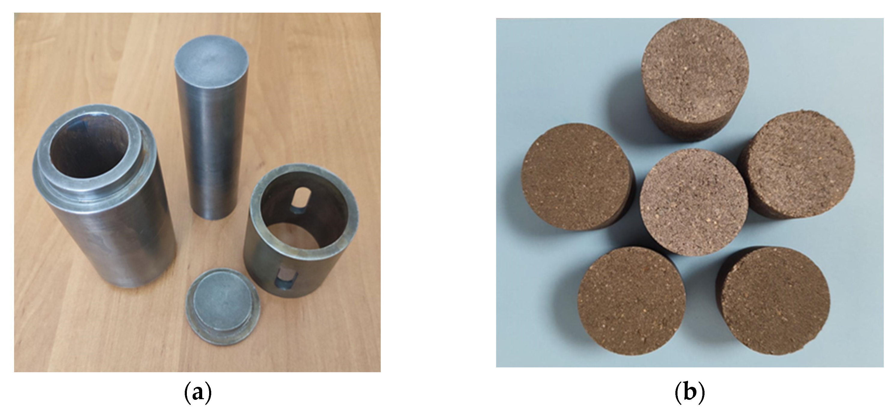
Mixtures for CO2 curing samples were prepared from binding materials and CEN standard sand; their cement content varied from 20 to 35 wt%. We weighed the required amounts of components and then poured them into sealed plastic containers. Then, 6 porcelain grinding bodies were put into them to guarantee the quality of homogenization, and the content was mixed in a homogenizer Turbula Type T2F (Willy A. Bachofen AG, Muttenz, Switzerland) for 1 h at 49 rpm. After completing this step, the mixtures were moistened to make the amount of water and binder correspond to the ratio frame w/c = 0.2–0.35. We then thoroughly mixed the content again in a porcelain dish. Then, cylinders measuring Ø36 × 36 ± 1 mm were pressed (while using 1.0 kN/s speed) to the required forming pressure with a hold of 20 s. Samples were formed and compressed (1.5 kN/s) according to Standard EN 196-1:2016 [26]; while using the universal testing machine FORM + TEST MEGA 10-400-50 (Seider&Co GmbH, Riedlingen, Germany). The formed samples were weighed to estimate the mass change after carbonization and promptly deposited in an autoclave to prevent drying. Pictures of the pressing mold and the formed samples are presented in Figure 2.
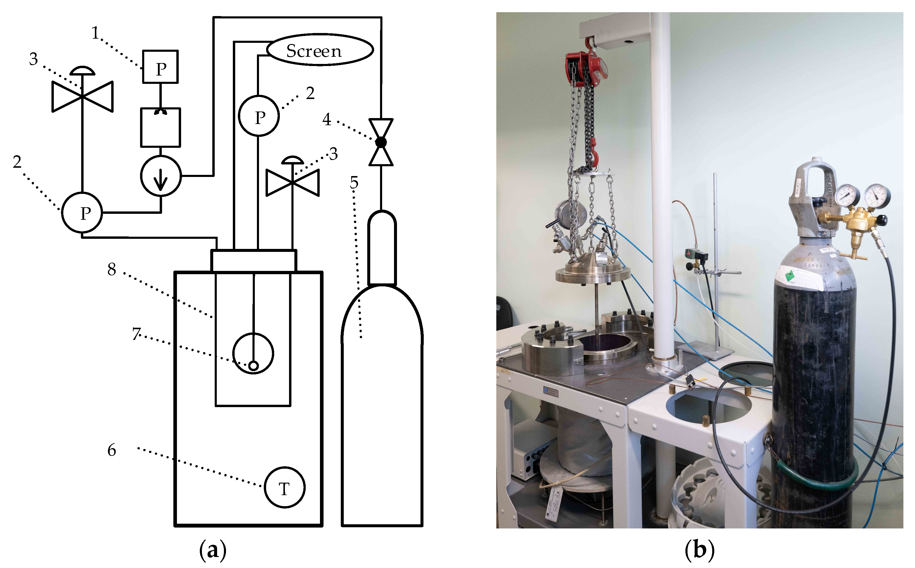
We implemented the process of carbonization in a Parr Instruments pressure reactor, model 4555 (Parr Instrument Company, Moline, IL, USA). The system diagram and a photo of the equipment in use are featured in Figure 3. Before solidification, the autoclave was filled twice with CO2 gas up to 2 bar, and immediately depressurized to atmospheric pressure so as to eliminate the presence of air. During the experiment, the reactor was filled with 99.9 wt% CO2 gas at a rate of 2.5 bar/min to the required value. At the end of the set holding time, the gas was released at the same rate. The samples were cured at a temperature of 25 and 45 °C under a pressure of 10–17.5 bar of carbon dioxide, and the holding time was 24 h (by following the procedure outlined in [29]). After completing the curing, weighing of the samples was performed, and, while the samples were still wet, their compressive strength was also determined. Each experiment involved the testing of at least 4 samples. A specimen weighing ~10 g was taken from one sample of each series, dried at a temperature of 100 ± 1 °C to a constant mass, crushed in an agate mortar, passed through a sieve with a mesh size of 80 µm, and investigated; instrumental analysis methods were employed.

2.2. Instrumental Analysis

For the investigation of the mineralogical composition of mortars (XRD, DSC, and TG), the center part of the samples was used for taking a specimen. With this objective, a hole measuring 10 mm in diameter and with a depth of 12 mm was drilled through the center towards the vertical axis. This material was extracted, and the hole was extended by a further 12 mm. This specimen, equidistant from the side walls of the cylindrical sample, was investigated.
The X-ray diffraction analysis (XRD) was implemented on the D8 Advance diffractometer (Bruker AXS GmbH, Karlsruhe, Germany) operating at a tube voltage of 40 kV and a tube current of 40 mA. The X-ray beam was filtered with a Ni 0.02 mm filter to select the CuKα wavelength. Bragg-Brentano geometry using a fast-counting detector Bruker Lynx Eye (Bruker AXS GmbH, Karlsruhe, Germany) based on the silicon strip technology served to record the diffraction patterns. The scanning of the samples over the range 2θ = 3–70° was implemented at a scanning speed of 6°·min−1 with the selection of the coupled two theta/theta scan type. The software Diffrac.Eva v3.0 (Bruker AXS GmbH, Karlsruhe, Germany) and the PDF-4 database were employed for the identification of the compounds.
The chemical composition analysis of the samples was conducted by X-ray fluorescence spectroscopy (XRF) on a Bruker X-ray S8 Tiger WD (Bruker AXS GmbH, Karlsruhe, Germany) spectrometer equipped with a Rh tube with energy of up to 60 keV. The materials were ground, put through a sieve with a 40-μm mesh, and compressed into tablets with a diameter of 40 mm, whereas a 20 kN force was being used. The measuring of the samples took place in a helium atmosphere, and the obtained data were processed with the SPECTRA Plus V.2 QUANT EXPRESS standardless software.
The thermal analyzer Linseis STA PT1000 (Linseis Massgeraete GmbH, Selb, Germany) was applied to simultaneous thermal analysis (STA; differential scanning calorimetric DSC, and thermogravimetry TG) studies. The heating was carried out under an N2 atmosphere at a heating rate of 10 °C·min−1 within the temperature range of 30 to 950 °C. Ceramic sample handlers were used for compound identification.
The amount of CO2 in the samples was determined with an automatic FOGL digital soil calcimeter (BD Inventions P.C., Thessaloniki, Greece). This method is simple and fast, and the results obtained are in good agreement with the data calculated from the mass loss from the DTG curves.
The specific surface area of the powders was measured by employing the Blaine method while using the electronic air permeability apparatus CE091 (Toni Technik Baustoff GmbH, Berlin, Germany). An Ultrapyc 1200e pycnometer (Quantachrome Instruments, Boynton Beach, FL, USA) served to establish the density of the investigated materials.

3. Results and Discussion

In theory, the carbonation process seems fairly simple, however, in reality, it is a complex process that depends on many and various parameters. The carbonation reaction of hydrated Portland cement in air is, overall, a slow process depending on the relative humidity of the environment, temperature, permeability of the concrete, and the concentration of the available CO2 [31]. In accelerated carbonation, the pressure value is an additional variable. According to Bertos et al. [32], the main factors that affect the carbonation process can be divided into two groups. The first of them is the reactivity of CO2: (1) the solid material has to possess certain chemical properties; (2) the water content in the material. Another group consists of diffusivity factors: (1) the physical properties of the solid—surface area, porosity, and compaction pressure; (2) CO2 partial pressure; (3) relative humidity; (4) temperature. As the process of carbonation is primarily diffusion-based, some of the factors affect the reaction path in a positive way, while others act contrarily. Considering the complexity of carbonation-affecting parameters, the most important point is to establish and research the coexistence and interaction of these factors upon the reaction course and kinetics.
During the research, the compressive strength of mortars was investigated based on the curing process parameters—CO2 pressure, exposure duration, and temperature, along with the sample properties itself—the binder/sand ratio, the water/cement ratio (w/c) ratio, and compaction. In order to detect the maximum conformity of all the parameters and to achieve the highest possible mechanical strength, after each experiment the condition at which the highest result was reached was chosen, and then the second parameter was changed, and so forth.
CO2 partial pressure can control the carbonation process which can be carried out at various pressure values from atmospheric to super-critical CO2 (scCO2). CO2 pressure, along with other process parameters, determines the course of the reaction [33] and, depending on the individual system, all the parameters should be set individually as well. When the temperature and pressure are increased, it is possible to increase the rate at which carbonation occurs in concrete. The obtained data are provided in Table 2.
When increasing the CO2 pressure from 10 to 17.5 bar, the strength of the mortar samples increased by ~20 wt%. Considering the compacting pressure, the samples reached the highest strength after the carbonation at 15 bar for 24 h and remained virtually stable when further increasing the pressure. The samples hardened as these conditions visually seemed to be fully carbonated, thus an increase in the pressure made no significant difference to longer-term carbonation. Considering more practical and economically viable implementation, a lower pressure for a longer period of time might be more advantageous. Thus, in the following experiments, these pressure and duration parameter values—15 bar and 24 h—were chosen as the most effective options.
In the next stage, the influence of the water content (w/c ratio) on the compressive strength of the samples and the amount of combined CO2 was determined. The data are presented in Table 3.
Changing the water-to-binder ratio had a noticeable impact on the strength of the samples (Table 3). When increasing the w/c ratio from 0.20 to 0.25, the compressive strength of 25 wt% of CEM II/A-LL 42.5R mortars increased, and it also reached the highest value of more than 38 MPa that was higher than the CEM 1 42.5 R sample strength at the same conditions. However, a further increase of the w/c ratio up to 0.35 led to a decrease in the compressive strength value. The cement samples, on the other hand, showed a continuous increase in the compressive strength value with the increasing water content and may have even failed to reach the peak value. This may be due to the fact that cement is a hydraulic material that initially forms calcium hydroxide and C-S-H, whose reactivity with CO2 might be higher than that of the initial calcium silicates. Since the blended cement contains 15% of opoka additive, a lower amount of these compounds gets formed. These results are in good agreement with data obtained by other authors [34]. An excess of water may limit the rate of carbonation by clogging the pores and reducing the diffusion of CO2, which subsequently leads to the faster accumulation of precipitation on the surface. At low water-to-cement ratios, the gas permeability is increased, and the CO2 effectively diffuses into the material, therefore, CO2 gas has to first dissolve in water to form carbonate ions (carbonic acid). When there is too little water, insufficient amounts of carbonic acid are produced for the Ca2+ ions in the pore solution to fully react. In addition, the capillary (open) porosity of cement depends on the water-to-cement ratio which also determines the transition zone porosity in the concrete structure [35]. Concrete with a high initial moisture level shows a much lower rate of carbonation due to the diffusion of CO2; carbonation becomes difficult when pores are saturated with water. Therefore, pore saturation plays a crucial role in the mechanism of carbonation. In blended cement, some of the pores are filled with finely dispersed opoka—this may be the reason why the products made from it need to be mixed with a smaller amount of water. So, a different water content may be required for different cement types in order to achieve the same degree of carbonation. Considering the above-discussed results, the water-to-binder ratio of 0.25 can be regarded as the optimum value for the CEM II/A-LL 42.5R binder system.
The diffusion efficiency of CO2 gas is also highly reliant on the structure, i.e., the porosity of the material. Therefore, compaction of the material prior to its carbonation also influences the final product. The porosity and permeability of the structure decreases with the increasing compaction, which might lead to greater strength development, however, when the compaction is high, the reaction surface is lower, and the water layer in pores is thicker. Since the diffusion of CO2 in water is slower than that in air, the early-age carbonation would be impeded [36]. However, water evaporation would become difficult, and this would provide moisture for carbonation at a later stage, thus, it would improve the total efficiency. On the other hand, the lower porosity hinders the diffusion of CO2 in the bulk material, which results in a lower carbonation rate and degree. In addition, lower compaction provides a higher reaction surface since the structure is then looser, however, water in such looser systems may evaporate faster during the carbonation process. Accordingly, to reach the highest possible compressive strength, the samples must be compacted at an optimum pressure while ensuring sufficient porosity for easy gas penetration and access to moisture.
The mortars were compacted by using different levels of pressure ranging from 7.5 to 15 MPa. The obtained results are provided in Table 4.
As can be seen in Table 3, the compressive strength of the mortars increased with the increasing compaction, and reached its highest value at 12.5–15 MPa. At a low compaction pressure of 7.5–10 MPa, the microstructure of the sample is evidently too loose, and calcium carbonate does not seem to be able to occupy the entire pore volume, which leads to the low final porosity of the sample and directly relates to the lower compressive strength. In contrast, compaction at pressures higher than 12.5 MPa seems to result in an excess sample density and low pore connectivity that most likely hindered the CO2 penetration to the sample core. Moreover, at a higher compaction, the pore volume is lower, and pores are more likely to be fully saturated with water. If the pore connectivity is poor, water has no path to move, and since it does not directly participate in the carbonation reaction, the formation of carbonates due to the low free space is also limited. Accordingly, compaction at 12.5 MPa seems to provide sufficient porosity and pore connectivity for the carbonation reaction to successfully proceed.
Since carbonation curing is a hardening process taking place in a gas environment, it is highly dependent on the diffusivity of the working gas. Thus, temperature has a significant impact on the attempt to reach a higher carbonation degree and hence to achieve increased mechanical properties of the system. A higher temperature increases CO2 diffusivity and promotes ion leaching and chemical reaction, however, it can reduce the CO2 solubility in water, thus decreasing the rate of carbonation. Due to these reasons, it is important to find the right balance between these limitations. The data are presented in Table 5.
The obtained compressive strength results (Table 2, Table 3 and Table 4) showed that the temperature increase had a negligible influence on the sample’s strength: when increasing the temperature from 25 to 45 °C, even though higher strength values were reached, the results were fluctuating and did not exhibit a linear dependence. Early-age carbonation is a highly exothermic reaction with temperature increases of up to ~60 °C for concrete [13], thus, the obtained cement result inconsistency may indicate that the ambient temperature of less than 60 °C may not exert a direct impact on the carbonation efficiency since the results fluctuated in a relatively low range of ±5 MPa. With a goal to achieve not only an efficient but also an economically balanced process, a temperature value of 25 °C was chosen for further experiments.
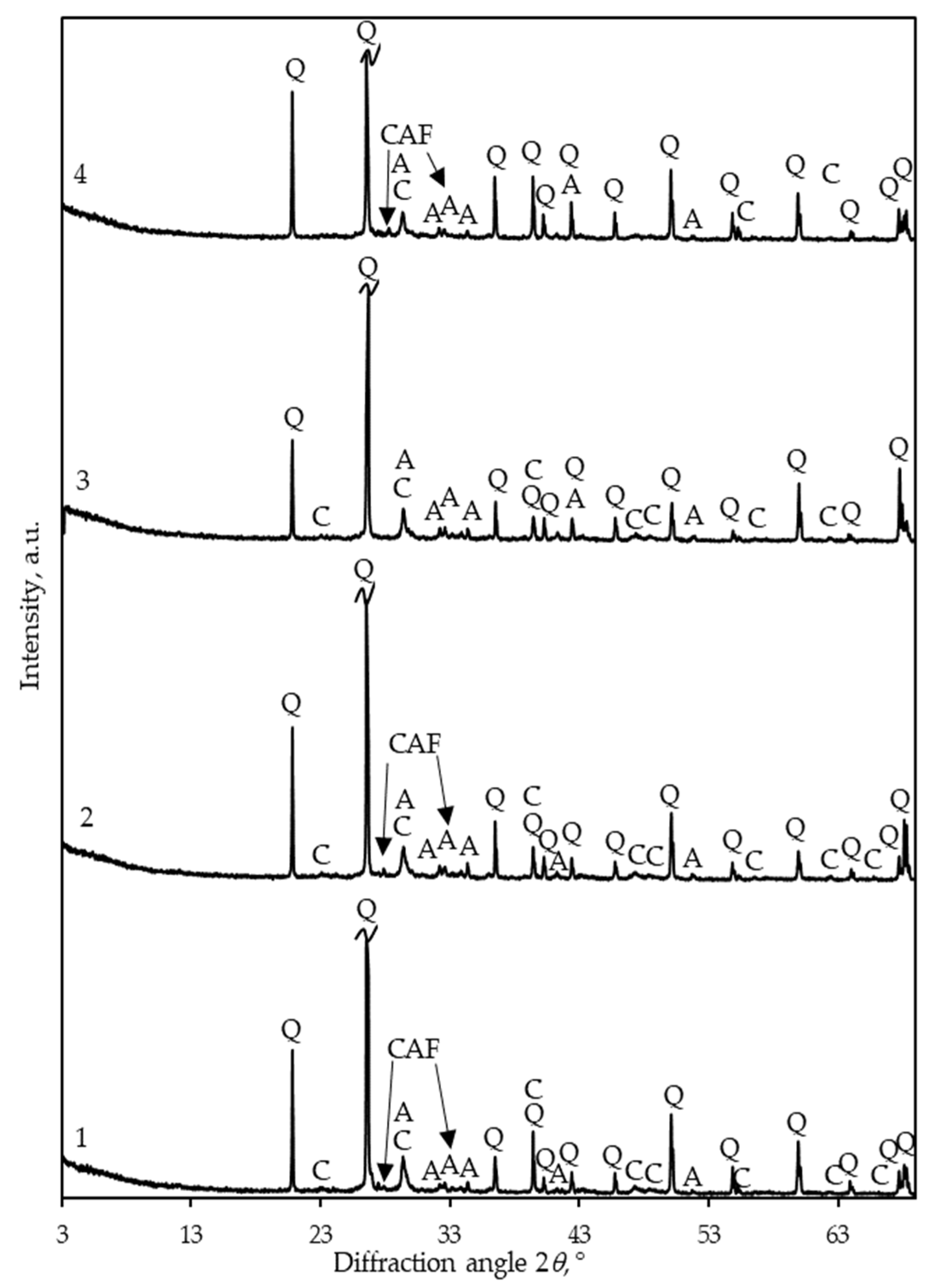
When examining the mineralogical composition of the samples hardened in the CO2 environment by the XRD method, it was found (Figure 4) that all curves are dominated by quartz peaks (d—0.335, 0.426, 0.182 nm; PDF No. 04-007-0522). This is natural because the forming mixes were made up of one part of binder and three parts of standard sand. Since the quartz peaks are very intense, it is impossible to determine in the XRD patterns what new compounds have formed. For this reason, the curves were corrected by significantly increasing their intensity and “cutting off” the quartz peaks at the same height.
The qualitative composition of the crystalline phases of the samples is close. In products with blended cement CEM II/A-LL 42.5R, regardless of its amount (Figure 4, curves 1 and 2), calcite CaCO3 (d—0.303, 0.187, 0.228 nm; PDF Nr. 04-008-0198) is formed during carbonization at a temperature of 25 °C. Small parts of unreacted alite 3CaO·SiO2 (d—0.278, 0.261, 0.275 nm; PDF Nr. 04-018-9702) and calcium aluminum iron silicate Ca5·Si2·(Fe,Al)18·O36 (d—0.260, 0.274, 0.320 nm; PDF Nr. 00-033-0250) also remain. After increasing the curing temperature to 45 °C, we identified no peaks of this compound in the XRD pattern anymore (Figure 4, curve 3). It should be noted that, when curing mortar samples in a CO2 environment, the dilution of OPC clinker by 15 wt% of opoka has no effect on the mineralogy of the crystalline phases since the same compounds are obtained anyway (Figure 4, curve 4).
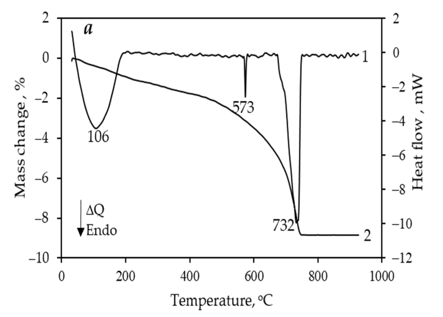
According to the thermal analysis data (Figure 5), all the samples absorb a small amount of water from the environment, as the mass loss in the temperature range of 50–200 °C is less than 1.25 wt%. The endothermic effect detected at a temperature of 573 °C is characteristic of the transition of α→β modifications of quartz. A very wide temperature range of CaCO3 decomposition (415–740 °C) means that the formed calcite is not only in crystalline, but also in amorphous form. In addition, a double exothermic effect with peaks at ∼863 and ∼896 °C was observed in the sample with CEM I 42.5 R, whereas these peaks were absent in the samples with CEM II/A-LL 42.5R. The first is typical for the formation of wollastonite CaO·SiO2, and the second for the formation of larnite 2CaO·SiO2. The reason for this difference is the composition of the cements. CEM II/A-LL 42.5R contains 15 wt% opoka (~7.5 wt% finely dispersed SiO2; Table 1). During carbonization, it does not react, but, during heat treatment, when CaCO3 is decomposed and highly active, CaO is formed, and it immediately starts to react with SiO2, even before the decarbonization process has finished. There is no such active form of silica in CEM I 42.5 R, and the CaO formed reacts with sufficiently inert quartz sand, and this takes place at a much higher temperature. The total mass loss of the samples formed from mixtures of the same composition and hardened under the same conditions, made from both cements, is very close: 7.7–7.8 wt%.
After testing laboratory samples and evaluating various factors, we are inclined to state that the optimal production conditions for mortars made of blended cement with 15% opoka additive and sand that harden in a CO2 environment are as follows: cement/sand ratio—1/3, water/cement ratio—0.3, compacting pressure—15 MPa, CO2 pressure in an autoclave—12.5 bar, duration—24 h, and temperature—25 °C.
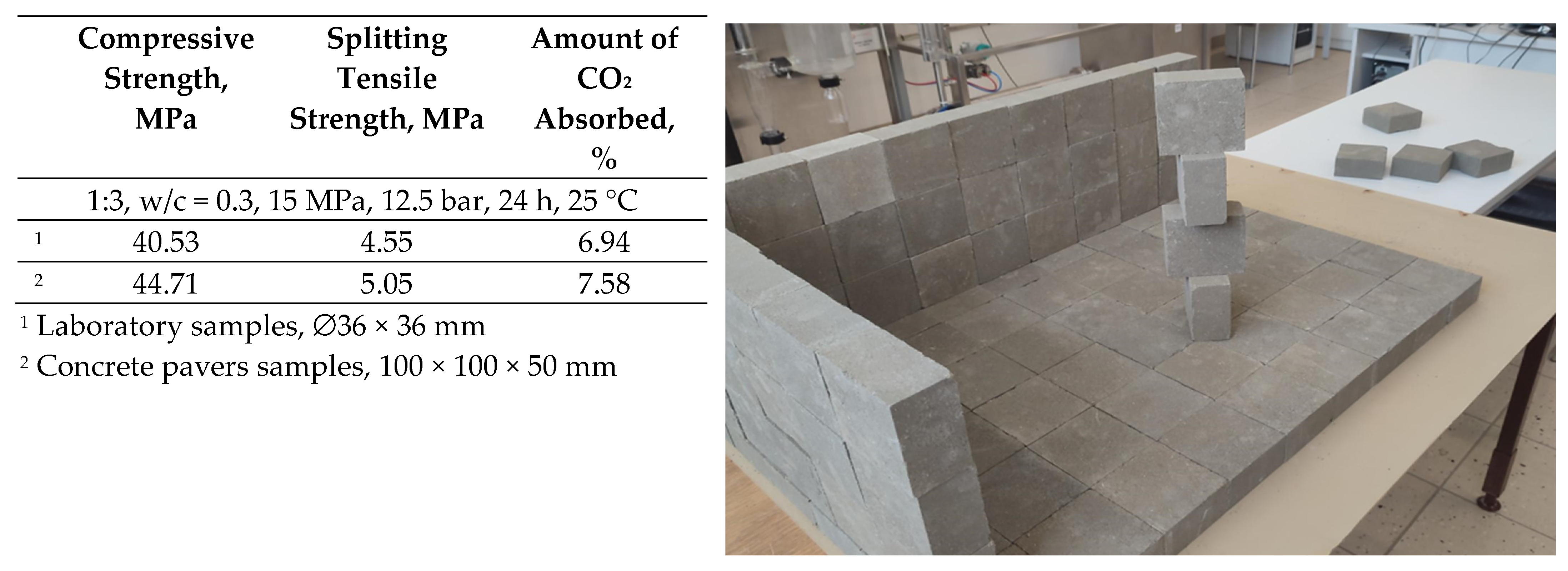
In accordance with them, concrete paver samples of industrial dimensions (100 × 100 × 50 mm) were produced. Compressive and splitting tensile strength were determined according to the methodology of the Standards EN 12390-3:2019 [37] and EN 12390-6:2023 [38]. The mineralogical composition was established by the XRD and STA methods. The main mechanical characteristics and a photo of paver samples are presented in Figure 6.
The higher strength of the concrete paver samples may be due to different dimensions from those of the laboratory specimens. Yet, there may be another reason to be considered, which is the composition of the initial mixtures. In the work, OPC was not used, but 15% opoka additive was employed. It is known that finely dispersed CaCO3 and amorphous SiO2 are formed during accelerated carbonization, which compacts the structure of the product. However, in this case, additional amounts of calcite and SiO2 were introduced by grinding the clinker with opoka, which contains up to 70% SiO2 and 20–40% calcite. The amorphous SiO2 in it is finely dispersed, therefore, it can increase the density.
In summary, it can be stated that composite cement with 15% opoka additive can be a promising binder for the production of mortars and concretes that harden in a CO2 environment. However, it is understandable that it will be possible to discuss this reliably only after durability tests have been carried out. Even though the determined mechanical properties of the carbonated mortars showed very favorable and promising results, the long-term durability performance of such a system plays a no less important part in pursuing improved alternative binder. Thus, the carbonated samples will, in the future, be exposed to water absorption by immersion, freeze–thaw, and abrasion resistance determination in order to ascertain their durability.

4. Conclusions

With increased CO2 emissions globally, there is a need to closely conduct carbonation tests on various cement-based materials. In this work, the influence of technological parameters on the process of the accelerated hardening of blended cement with an opoka additive in a CO2 environment was investigated, the main properties and the mineralogical composition of the obtained products were determined, and they were compared with the characteristics of samples based on Ordinary Portland cement (OPC). Within the scope of the present study, the following conclusions and remarks are drawn:
  • It was determined that the blended cement with a 15 wt% opoka additive is a suitable cementitious material for high-strength carbonated mortar products, and it has a lower negative impact on the environment due to the reduced amount of OPC clinker, combined with carbonation curing and permanent CO2 sequestration.
  • When curing mortar samples in a CO2 environment, the replacement of OPC clinker with 15% opoka has no effect on the qualitative composition of the crystalline phases of the products: in both cases, calcite forms, and small parts of unreacted alite and calcium aluminum iron silicate remain.
  • Concrete pavers of industrial dimensions with a compressive strength of ~45 MPa can be produced from cement blended with opoka and sand mixtures when carbonation is performed at the following conditions: cement/sand ratio—1/3, water/cement ratio—0.3, compacting pressure—15 MPa, CO2 pressure—12.5 bar, duration—24 h, and temperature—25 °C. The strength properties have been found to be similar or even better than those of samples based on OPC.

Author Contributions

Conceptualization, R.S. and A.E.; methodology, E.P. and Z.V.; formal analysis, R.S., E.P. and Z.V.; investigation, E.P. and Z.V.; resources, R.S., E.P., Z.V. and A.E.; data curation, E.P. and Z.V.; writing—original draft, E.P.; writing—review and editing, R.S.; visualization, A.E.; supervision, R.S.; funding acquisition, A.E. All authors have read and agreed to the published version of the manuscript.

Funding

This research received no external funding.

Institutional Review Board Statement

Not applicable.

Informed Consent Statement

Not applicable.

Data Availability Statement

The data that support the findings of this study are available from the corresponding author, R.S., upon reasonable request.

Conflicts of Interest

Arunas Elsteris is the Director of JSC Ecostone Solutions, but this work is not directly related to the company’s activities. The remaining authors declare that the research was conducted in the absence of any commercial or financial relationships that could be construed as a potential conflict of interest.

References

  1. World Economic Forum, Nature Positive: Role of the Cement and Concrete Sector. 2023. Available online: https://www3.weforum.org/docs/WEF_Nature_Positive_Role_of_the_Cement_and_Concrete_Sector_2023.pdf (accessed on 15 July 2024).
  2. Supriya; Chaudhury, R.; Sharma, U.; Thapliyal, P.C.; Singh, L.P. Low-CO2 emission strategies to achieve net zero target in cement sector. J. Clean. Prod. 2023, 417, 137466. [Google Scholar] [CrossRef]
  3. Dadsetan, S.; Siad, H.; Lachemi, M.; Mahmoodi, O.; Şahmaran, M. Geopolymer binders containing construction and demolition waste. In Handbook of Sustainable Concrete and Industrial Waste Management; Woodhead Publishing in Civil and Structural Engineering: Cambridge, UK, 2022; pp. 437–474. [Google Scholar] [CrossRef]
  4. Beguedou, E.; Narra, S.; Armoo, E.A.; Agboka, K.; Damgou, M.K. Alternative fuels substitution in cement industries for improved energy efficiency and sustainability. Energies 2023, 16, 3533. [Google Scholar] [CrossRef]
  5. Mohamad, N.; Muthusamy, K.; Embong, R.; Kusbiantoro, A.; Hashim, M.H. Environmental impact of cement production and solutions: A review. Matter. Today Proc. 2022, 48, 741–746. [Google Scholar] [CrossRef]
  6. Snellings, R.; Suraneni, P.; Skibsted, J. Future and emerging supplementary cementitious materials. Cem. Concr. Res. 2023, 171, 107199. [Google Scholar] [CrossRef]
  7. Song, O.; Guo, M.Z.; Gu, Y.; Ling, T.C. CO2 curing of SCMs blended cement blocks subject to elevated temperatures. Constr. Build. Mater. 2023, 374, 130907. [Google Scholar] [CrossRef]
  8. Alsalman, A.; Assi, L.N.; Kareem, R.S.; Carter, K.; Ziehl, P. Energy and CO2 emission assessments of alkali-activated concrete and Ordinary Portland Cement concrete: A comparative analysis of different grades of concrete. Clean. Environ. Syst. 2021, 3, 100047. [Google Scholar] [CrossRef]
  9. Sahu, S.; DeCristofaro, N. Solidia Cement. Solidia Technologies. 2013. Available online: https://www.semanticscholar.org/paper/Solidia-Cement-TM-Part-One-of-a-Two-Part-Series-the-Sahu-Decristofaro/691a16464fff1a9379e23f30f487cc0e9c846f5e (accessed on 7 August 2023).
  10. Ashraf, W.; Olek, J. Carbonation behavior of hydraulic and non-hydraulic calcium silicates: Potential of utilizing low-lime calcium silicates in cement-based materials. J. Mater. Sci. 2016, 51, 6173–6191. [Google Scholar] [CrossRef]
  11. El-Hassan, H.; Shao, Y. Carbon storage through concrete block carbonation. J. Clean Energy Technol. 2014, 2, 287–291. [Google Scholar] [CrossRef]
  12. Savija, B.; Lukovic, M. Carbonation of cement paste: Understanding, challenges, and opportunities. Constr. Build. Mater. 2016, 117, 285–301. [Google Scholar] [CrossRef]
  13. Zhang, D.; Ghouleh, Z.; Shao, Y. Review on carbonation curing of cement-based materials. J. CO2 Util. 2017, 21, 119–131. [Google Scholar] [CrossRef]
  14. Winnefeld, F.; Leemann, A.; German, A.; Lothenbach, B. CO2 storage in cement and concrete by mineral carbonation. Curr. Opin. Green Sustain. Chem. 2022, 38, 100672. [Google Scholar] [CrossRef]
  15. Blended Cement—Green, Durable & Sustainable. Global Cement and Concrete Association, India. 2022. Available online: https://gccassociation.org/wp-content/uploads/2022/04/Report_Blended-Cement-Green-Duratable-Sustainable_13Apr2022.pdf (accessed on 15 July 2024).
  16. Rhaouti, Y.; Taha, Y.; Benzaazoua, M. Assessment of the Environmental Performance of Blended Cements from a Life Cycle Perspective: A Systematic Review. Sustain. Prod. Consum. 2023, 36, 32–48. [Google Scholar] [CrossRef]
  17. Boscaro, F.; Palacios, M.; Robert, J. Flatt Formulation of low clinker blended cements and concrete with enhanced fresh and hardened properties. Cem. Concr. Res. 2021, 150, 106605. [Google Scholar] [CrossRef]
  18. Bizley, D. Thyssenkrupp Polysius Presents New Meca-Clay Clinker Reduction Solution. World Cement. 2023. Available online: https://www.worldcement.com/product-news/12122023/thyssenkrupp-polysius-presents-new-meca-clay-clinker-reduction-solution/ (accessed on 15 July 2024).
  19. Reddy, S.S.; Reddy, M.A.K.M. Lime calcined clay cement (LC3): A review. IOP Conf. Ser. Earth Environ Sci. 2021, 796, 012037. [Google Scholar] [CrossRef]
  20. Wang, L.; Rehman, N.U.; Curosu, I.; Zhu, Z.; Beigh, M.A.B.; Liebscher, M.; Chen, L.; Tsang, D.C.W.; Hempel, S.; Mechtcherine, V. On the use of limestone calcined clay cement (LC3) in high-strength strain hardening cement-based composites (HS-SHCC). Cem. Concr. Res. 2021, 144, 106421. [Google Scholar] [CrossRef]
  21. Yu, J.; Wu, H.L.; Mishra, D.K.; Li, G.; Leung, C.K.Y. Compressive strength and environmental impact of sustainable blended cement with high-dosage limestone and calcined clay (LC2). J. Clean. Prod. 2021, 278, 123616. [Google Scholar] [CrossRef]
  22. García-Segura, T.; Yepes, V.; Alcalá, J. Life cycle greenhouse gas emissions of blended cement concrete including carbonation and durability. Int. J. Life Cycle Assess. 2014, 19, 3–12. [Google Scholar] [CrossRef]
  23. Seo, J.H.; Amr, I.T.; Park, S.M.; Bamagain, R.A.; Fadhel, B.A.; Kim, G.M.; Hunaidy, A.S.; Lee, H.K. CO2 Uptake of Carbonation-Cured Cement Blended with Ground Volcanic Ash. Materials 2018, 11, 2187. [Google Scholar] [CrossRef] [PubMed]
  24. Liu, W.; Lin, S.; Li, Y.; Long, W.; Dong, Z.; Tang, L. Slag Blended Cement Paste Carbonation under Different CO2 Concentrations: Controls on Mineralogy and Morphology of Products. Materials 2020, 13, 3404. [Google Scholar] [CrossRef]
  25. Kuzielová, E.; Slaný, M.; Žemlička, M.; Másilko, J. Accelerated carbonation of oil-well cement blended with pozzolans and latent hydraulic materials. J. Therm. Anal. Calorim. 2023, 148, 9963–9977. [Google Scholar] [CrossRef]
  26. EN 196-1:2016; Methods of Testing Cement—Part 1: Determination of Strength. The European Committee for Standardization: Brussels, Belgium, 2016.
  27. Gasiūnienė, V.E. Lietuvos Kietosios Naudingosios Iškasenos = Lithuanian Solid Mineral Resources; Lietuvos Geologijos Tarnyba: Vilnius, Lithuania, 1998; pp. 5–14, 19–20, 30–31. (In Lithuanian) [Google Scholar]
  28. Siauciunas, R.; Mikaliunaite, J.; Urbonas, L.; Baltakys, K. Tribochemical and thermal activation of α-C2S hydrate as precursor for cementitious binders. J. Therm. Anal. Calorim. 2014, 118, 817–823. [Google Scholar] [CrossRef]
  29. Smigelskyte, A.; Siauciunas, R.; Hilbig, H.; Decker, M.; Urbonas, L.; Skripkiunas, G. Carbonated rankinite binder: Effect of curing parameters on microstructure, strength development and durability performance. Sci. Rep. 2020, 10, 14462. [Google Scholar] [CrossRef] [PubMed]
  30. Siauciunas, R.; Prichockiene, E.; Valancius, Z. The influence of Mg-impurities in raw materials on the synthesis of rankinite clinker and the strength of mortar hardening in CO2 environment. Materials 2023, 16, 2930. [Google Scholar] [CrossRef] [PubMed]
  31. Naik, T.N.; Kumar, R.; Kraus, N.R. Carbon Dioxide Sequestration in Cementitious Products. In Report Submitted to the Electric Power Research Institute, Palo Alto, California. [Interactive]. 2009. Available online: https://typeset.io/papers/carbon-dioxide-sequestration-in-cementitious-products-117rn0mb58 (accessed on 6 June 2024).
  32. Fernandez Bertos, M.; Simons, S.J.R.; Hills, C.D.; Carey, P.J. A review of accelerated carbonation technology in the treatment of cement-based materials and sequestration of CO2. J. Hazard. Mater. 2004, 112, 193–205. [Google Scholar] [CrossRef]
  33. Wang, T.; Huang, H.; Hu, X.; Fang, M.; Luo, Z.; Guo, R. Accelerated mineral carbonation curing of cement paste for CO2 sequestration and enhanced properties of blended calcium silicate. Chem. Eng. J. 2017, 323, 320–329. [Google Scholar] [CrossRef]
  34. Klemm, W.A.; Berger, R.L. Accelerated curing of cementitious systems by carbon dioxide: Part I. Portland cement. Cem. Concr. Res. 1972, 2, 567–576. [Google Scholar] [CrossRef]
  35. Kumar, R.; Bhattacharjee, B. Porosity, pore size distribution and in situ strength of concrete. Cem. Concr. Res. 2003, 33, 155–164. [Google Scholar] [CrossRef]
  36. Fang, Y.; Chang, J.; Cao, M. Influence of compaction pressure on the accelerated carbonation of calcium hydroxide. J. Wuhan Univ. Technol. 2016, 31, 1187–1192. [Google Scholar] [CrossRef]
  37. EN 12390-3:2019; Testing Hardened Concrete—Part 3: Compressive Strength of Test Specimens. The European Committee for Standardization: Brussels, Belgium, 2019.
  38. EN 12390-6:2023; Testing Hardened Concrete—Part 6: Tensile splitting Strength of Test Specimens. The European Committee for Standardization: Brussels, Belgium, 2023.
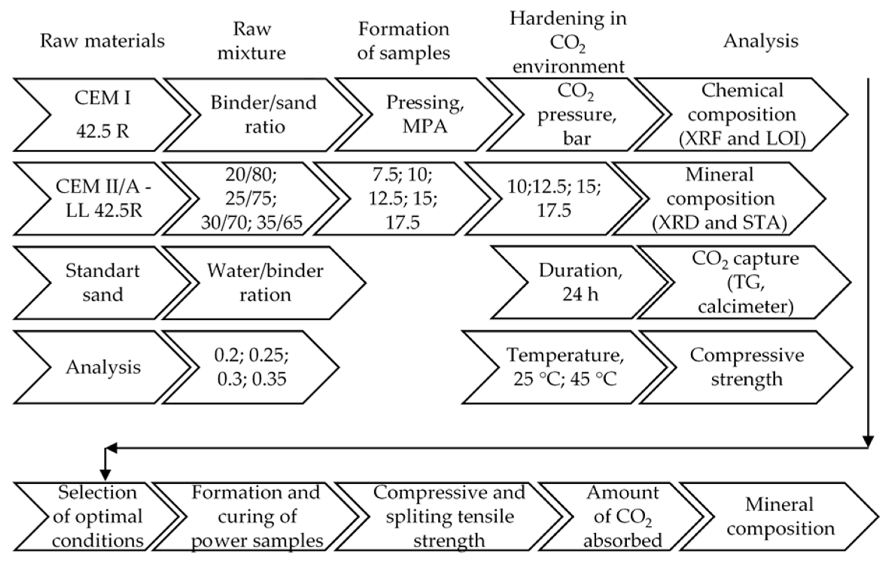
Figure 1. Raw materials, preparation of samples, their hardening parameters, and their determined properties.
Ceramics 07 00086 g001
Figure 2. Pictures of the pressing mold (a) and formed samples (b).
Ceramics 07 00086 g002
Figure 3. Technological system of samples hardening in CO2 environment adapted from [30], MDPI, 2023 (a) and picture of the Parr Instruments pressure reactor 4555 (b): 1—pneumatic pump; 2—manometers; 3—shutters; 4—ball valve; 5—CO2 gas cylinder; 6—temperature sensor; 7—autoclave; 8—heater-thermostat.
Ceramics 07 00086 g003
Figure 4. XRD patterns of samples (w/c—0.25, compacting pressure—12.5 MPa, curing time in 15 bar CO2 environment—24 h), when: 1—20 wt% CEM II/A-LL 42.5R, 25 °C; 2—30 wt% CEM II/A-LL 42.5R, 25 °C; 3—30 wt% CEM II/A-LL 42.5R, 45 °C; 4—30 wt% CEM 1 42.5 R, 25 °C. Indexes: C—calcite, A—alite, Q—quartz, CAF—calcium aluminum iron silicate.
Ceramics 07 00086 g004
Figure 5. STA (1—DSC, 2—TGA) curves of samples (cement/sand ratio—1:3, w/c—0.25, compacting pressure—12.5 MPa, curing time in 15 bar CO2 environment—24 h), when: (a) CEM II/A-LL 42.5R, 25 °C; (b) CEM II/A-LL 42.5R, 45 °C; (c) CEM 1 42.5 R, 25 °C.
Ceramics 07 00086 g005aCeramics 07 00086 g005b
Figure 6. The main characteristics and photo of concrete pawer samples.
Ceramics 07 00086 g006
Table 1. Oxide composition of binders and carbonated opoka.
MaterialCaOSiO2Al2O3K2ONa2OMgOFe2O3SO3OtherLOI
CEM 1 42.5 R64.420.45.40.770.221.42.62.70.51.87
CEM II/A-LL 42.5R62.121.95.10.740.181.532.452.60.323.08
Opoka26.150.62.530.830.090.551.660.580.7416.41
Table 2. The dependence of the compressive strength of the samples and the amount of CO2 absorbed on the CO2 pressure in a reactor; 30 wt% CEM II/A-LL 42.5R + 70 wt% sand; w/c = 0.25, curing duration—24 h; temperature—25 °C.
No.CO2 Pressure in a Reactor, BarCompacting Pressure, MPaCompressive Strength, MPaMass Increase, gAdsorbed CO2, wt%
1101544.673.266.90
212.51550.324.167.69
31512.552.713.957.40
4151553.723.906.95
517.51551.204.027.05
Table 3. The dependence of the compressive strength of the samples and the amount of CO2 absorbed on the composition and humidity of the forming mixture (compacting pressure—12.5 MPa; CO2 atmosphere—15 bar; 24 h; 25 °C.
No.Composition of the Mixturew/c RatioCompressive Strength, MPaMass Increase, gAdsorbed CO2, wt%
125 wt% of CEM II/A-LL 42.5R and 75 wt% of sand0.231.133.586.63
20.2538.533.316.94
30.332.233.076.30
40.3524.172.976.07
525 wt% of CEM I 42.5 R and 75 wt% of sand0.2535.55
60.338.12
70.3541.62
830 wt% of CEM II/A-LL 42.5R and 70 wt% of sand0.233.454.35
90.2552.713.957.40
100.344.662.89
110.3537.552.41
1235 wt% of CEM II/A-LL 42.5R and 65 wt% of sand0.265.634.80
130.2553.864.197.9
140.339.433.23
Table 4. The dependence of the compressive strength of the samples and the amount of CO2 absorbed on the composition and compacting pressure; w/c = 0.25, CO2 atmosphere—15 bar; 24 h; 25 °C.
No.Composition of the MixtureCompacting Pressure, MPaCompressive Strength, MPaMass Increase, gAdsorbed CO2, wt%
125 wt% of CEM II/A-LL 42.5R and 75 wt% of sand7.532.313.136.82
21034.213.307.11
312.538.533.356.94
41540.383.646.75
525 wt% of CEM I 42.5 R and 75 wt% of sand12.535.55
61540.88
717.532.55
830 wt% of CEM II/A-LL 42.5R and 70 wt% of sand7.538.534.517.96
91045.674.127.78
1012.552.713.927.402
111553.724.056.95
Table 5. The compressive strength of the samples and the amount of CO2 absorbed, when w/c = 0.25, compacting pressure—12.5 or 15 MPa; atmosphere—15 bar; 24 h; temperature—45 °C.
No.CEM II/A-LL 42.5R Content in the MixtureCompacting PressureCompressive Strength, MPaMass Increase, gAdsorbed CO2, wt%
12012.525.071.865.29
22512.536.692.226.25
3 *2512.535.85
4251538.422.646.64
53012.546.093.377.24
63512.552.083.727.78
* CEM I 42.5 R.
Disclaimer/Publisher’s Note: The statements, opinions and data contained in all publications are solely those of the individual author(s) and contributor(s) and not of MDPI and/or the editor(s). MDPI and/or the editor(s) disclaim responsibility for any injury to people or property resulting from any ideas, methods, instructions or products referred to in the content.