
Effects of Nanofiber Interleaving on the Strength and Failure Behavior of Co-Cured Composite Joints with Fiber Orientation Mismatch


Abstract
1. Introduction
2. Experimental Section
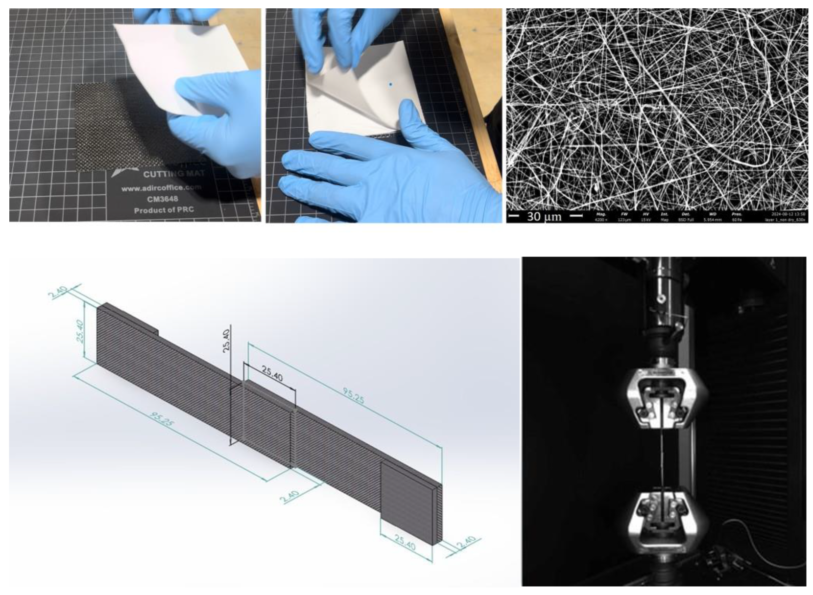
- Prepreg lay-up: Carefully layering prepreg composite materials.
- Integration of nanofibers at the bond interface: Incorporating nanofibrous veils into the bond line to enhance mechanical performance and optimize the adhesion characteristics.
- Cutting lap joint samples: Shaping the bonded samples to precise geometrical dimensions for accurate and reproducible mechanical testing.
- Tensile testing of bonded lap joints: Evaluating the mechanical strength and failure modes of the samples using tensile testing techniques.
- Scanning electron microscope (SEM) analysis: Conducting a detailed analysis of the bonded coupons post-testing to assess the bonding quality, fiber distribution, and failure mechanisms.
2.1. Material Selection
2.2. Lap Joint Design and Preparation
2.3. Manufacturing of Co-Cured SLJ Samples
2.4. Mechanical Testing
2.5. Electron Microscopy
3. Results and Discussion
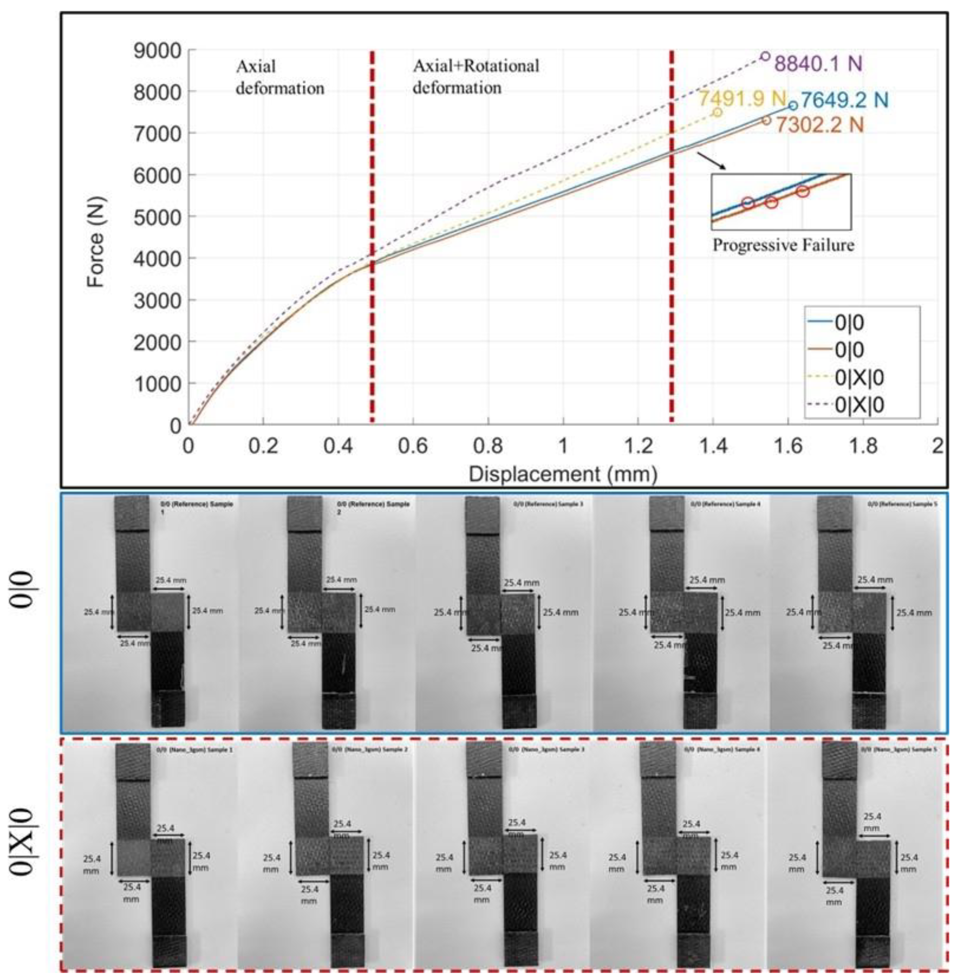
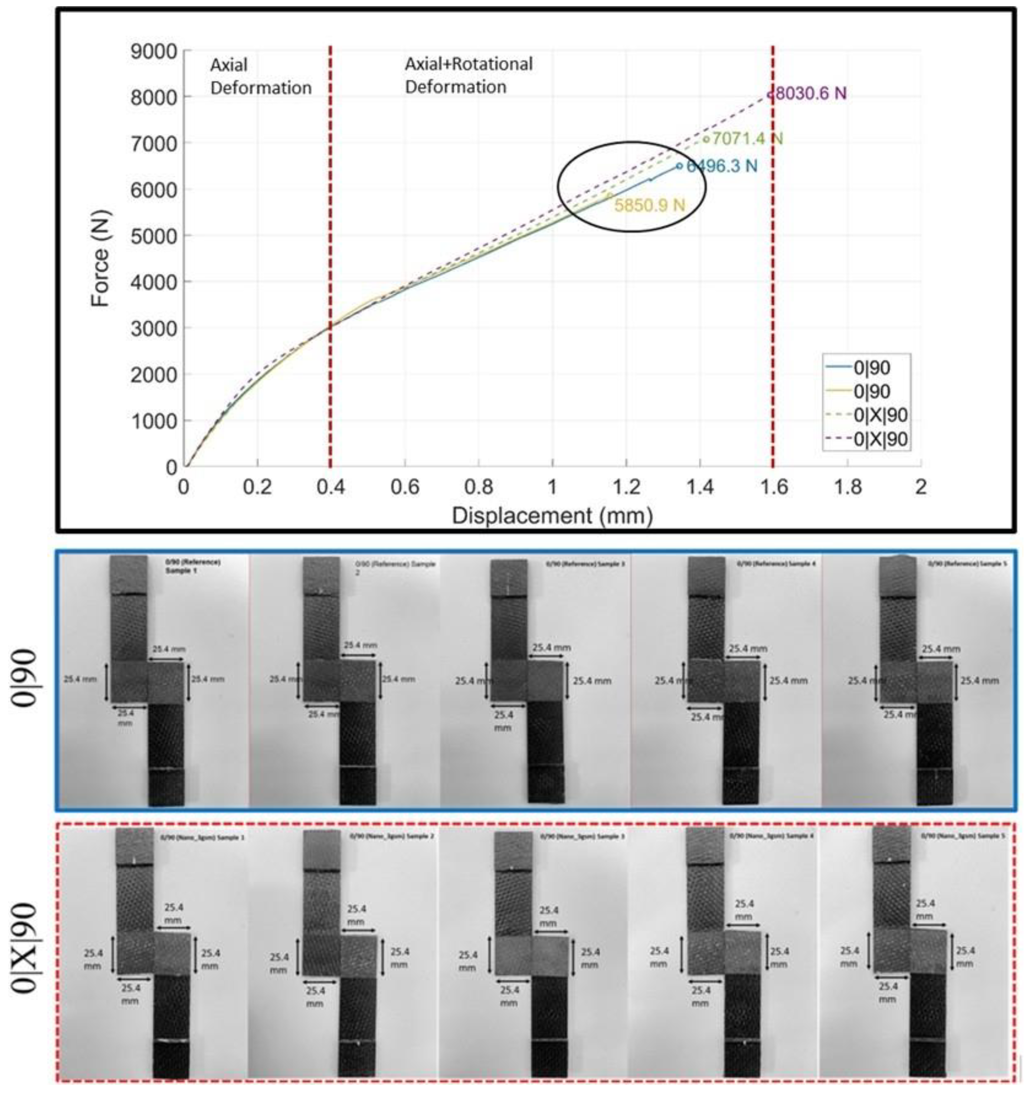
3.1. Mechanical Test Data and Statistical Analysis
3.2. (0|0) and (0|X|0) Joint Interfaces
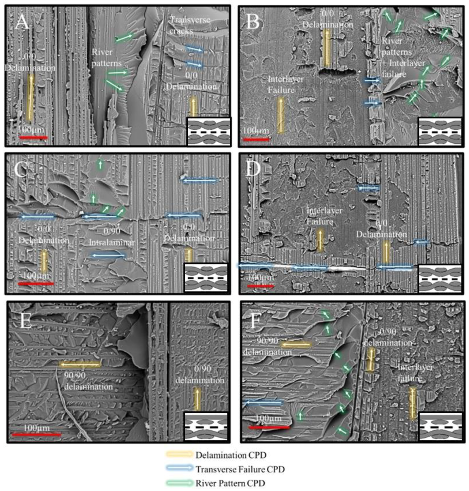
 yarn crimp toward a 0/0 delamination surface was captured in the image. Step-wise damage formation in the featureless resin phase exhibits parallel-aligned river patterns, providing direct evidence of intralaminar damage at 90° transitioning into interlaminar damage at the (0|0) interface. An investigation of the region of interest with similar damage progression in (0|X|0) (Figure 6D) suggests that the interlaminar propagation of a transverse crack at the 90° yarn crimp reveals the nanofiber-toughened nanocomposite region, rather than the weaker resin phase observed in Figure 6C. This observation provides strong evidence of the nanofibrous interlayers’ capability to toughen resin-rich interlaminar regions and enhance crack deflection.
 occurs within the 8HS ply (Figure 6E). The weft (90°) and warp (0°) yarns were distinctly separated, with a visible chunk of excess resin at their junction. Mode I-dominated 0/90 delamination was observed progressing in the 0° direction, while mode II-dominated delamination occurred on the 90° yarn. The failure at the excess resin chunk appeared smooth, lacking river pattern formations, suggesting a highly unstable crack initiation from the crimping region toward the 90° yarn. This is also evident from the decreasing size of the hackle patterns when traced from the yarn intersection site toward the 90° yarn. A similar region of interest at the yarn intersection for the (0|X|0) case is shown in Figure 6F. Unlike Figure 6E, there is no distinct separation between 0° and 90° yarns, and an excess resin phase is present, now exhibiting river patterns. The delamination pattern in the 0° yarn alternated between interlayer failure and mode II-dominated crack propagation [41] at the 0/90 interface. The reduction in the mode I component of the mixed-mode fracture may have mitigated critical separation in yarn intersections, enabling more stable crack propagation from the resin-rich regions, now characterized by distinct river patterns. However, this observation cannot be generalized due to the inherent variability in the amount of excess resin and yarn/yarn interfaces in textile-based composites [42].
3.3. (90|90) and (90|X|90) Joint Interfaces
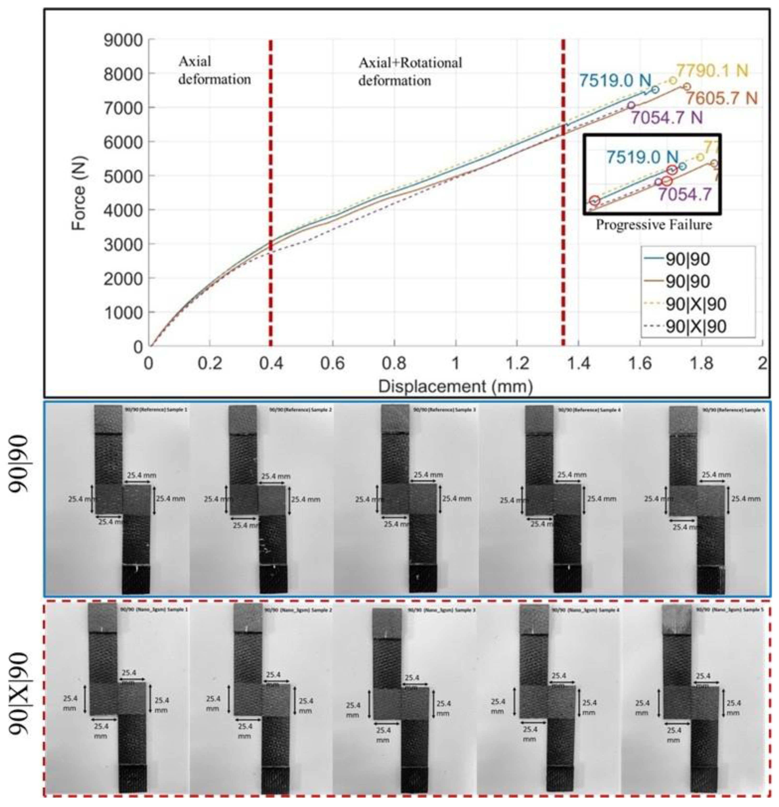
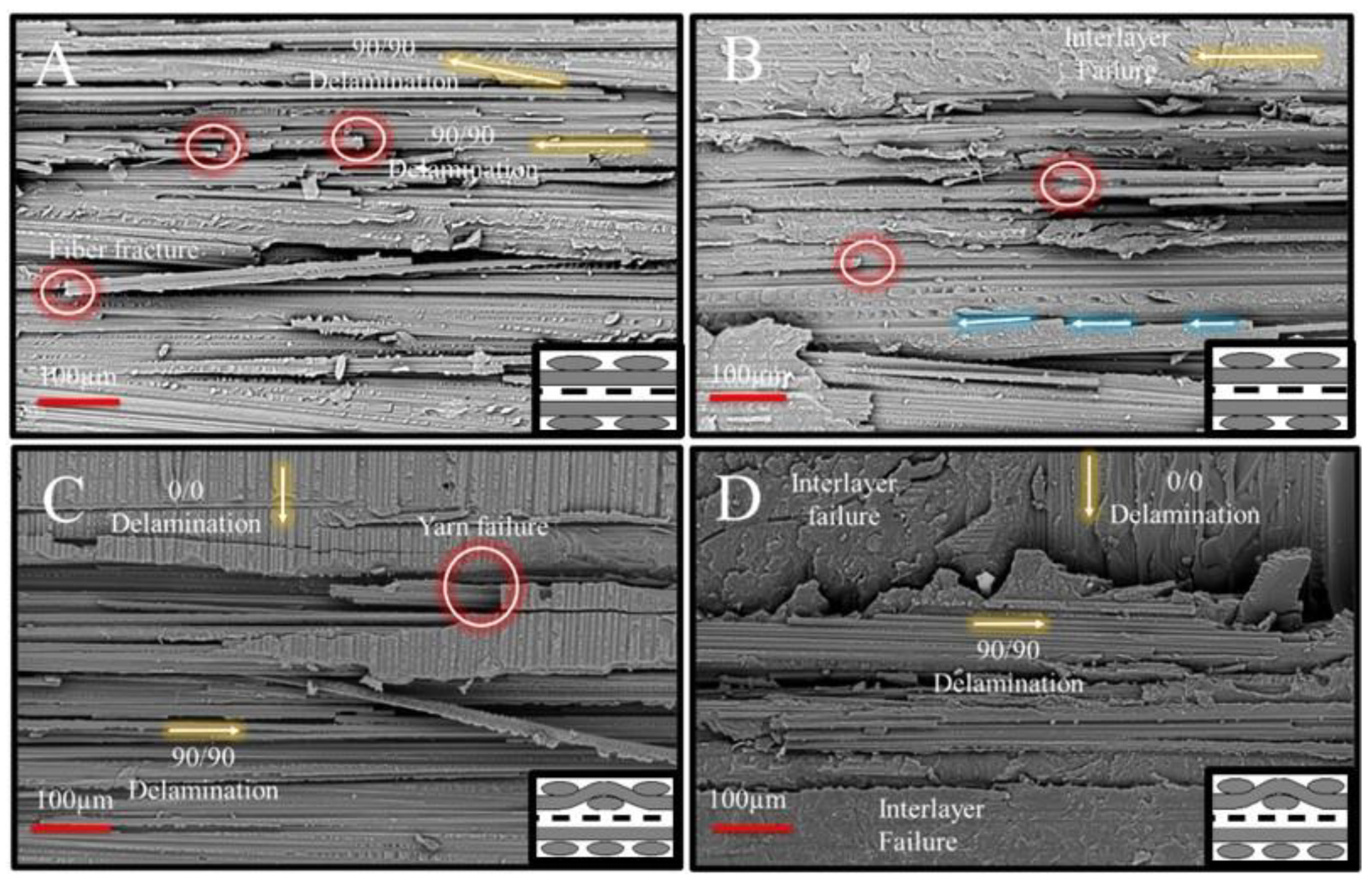
 yarns of the (90|90) adherent interface (Figure 8A). While the dominant failure mode in this region was 90/90 delamination, several other failure events occurred alongside the delamination, suggesting a more complicated progression. First, the intensity of the 90° yarn failures was notably high on the fracture surface, characterized by multiple fiber fractures (highlighted in red circles) and localized yarn splitting due to the separation of fiber blocks. Second, a change in the crack propagation direction was observed, particularly near areas exhibiting fiber fracture and yarn splitting. This indicates the coexistence of multiple failure modes during specimen failure, including 90/90 delamination, fiber fracture, yarn splitting, and shear failure. Additionally, the fracture surfaces showed no clear evidence suggesting that the transverse failure events directly caused the delamination. Therefore, it can be concluded that critical crack initiation responsible for yarn/yarn delamination originated elsewhere and propagated along the (90|90) interface, accompanied by the co-existence of 90° transverse failure and shear failure, potentially induced by specimen rotation.
 yarns. Crimping locations appear to have been critically loaded during mechanical loading, serving as potential crack initiation sites. An important region of interest, where interlayer failure dominated the fracture surface except at the crimping location, is shown in Figure 8D. In this region, two interlayer failure zones—one at the upper 90° yarn and another at the lower 0° yarns—were separated by a critical yarn failure event occurring in the 90° yarns. This observation is also significant in understanding the effectiveness of nanofibers (Table 4) to mitigate transverse failure events, whether in un-crimped 90/90 interfaces or at the yarn intersection (crack jump locations). Given this limitation, no improvements in lap shear failure load were achieved, suggesting that while nanofibers may enhance specific interfacial properties, their influence on specific critical failure mechanisms, such as transverse cracking and yarn splitting, remained minimal (Table 4).
3.4. (0|90) and (0|X|90) Joint Interfaces
 interface (Figure 10A). Two significant changes were observed: (i) a reduction in the mode II component of crack propagation and (ii) larger transverse fracture events on the 0/0 yarns compared to those in Figure 6A. Both observations strongly suggest a reduction in the fracture toughness at the intermittent 0/0 yarn interface sites of the (0|90) joint interface case. A similar region of interest in the 0/0 yarn lap of the (0|X|90) joint interface (Figure 10B), where significant interlayer failure was observed, suggested an improved ability of nanofibers to enhance delamination resistance at the 0/0 yarn interface sites. This observation was somewhat similar to the behavior seen in the (0|0) joint interface case.
 between the 0° and 90° yarns. However, it is interpreted that a direct crack propagation route exists through the split 0° fibers and excess resin. This route connects the lower 0° yarn, where the failure mode was 0/90 delamination (note the 90° marks over the warp 0° yarn, left half of Figure 10C), to the intermittent lap of the 90° yarns, which exhibited mode I-dominated 90/90 delamination. This observation suggests that the proximity of crimping and 0/90 yarn intersections facilitated frequent crack jumps at the joint interfaces. The resulting difference in mechanical test results indicates that these crack jumps had a tangible negative impact on lap shear strength. However, the nanofibrous interlayers played a crucial role in mitigating this effect: for the (0|X|90) joint interface (Figure 10D), unlike all previous cases, the nanofibrous interlayers provided significant resistance at the crack jump locations, ultimately preventing layer separation and leading a drastic increase in lap shear strength (Table 4).
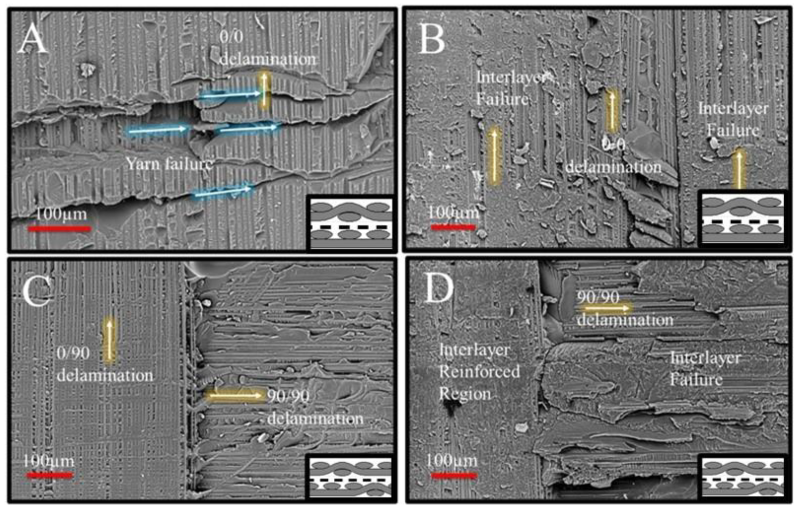
4. Conclusions
Author Contributions
Funding
Data Availability Statement
Acknowledgments
Conflicts of Interest
Nomenclature
| 8HS | Eight-Harness Satin. |
{90/0} →  | Notation for an 8HS ply (no flip)—dominance of 90° yarns on the bottom surface and 0° yarns on the top surface. |
{0/90} →  | Notation for an 8HS ply (flipped)—dominance of 0° yarns on the bottom surface and 90° yarns on the top surface. |
| X | XantuLayr nanofiber interlayer—indicating that a nanofibrous veil was co-cured at the bond line. |
| (0|0) | At the bond interface—both adherends have fibers/yarns dominantly aligned in the 0° direction (warp direction). |
| (90|90) | At the bond interface—both adherends have fibers/yarns dominantly aligned in the 90° direction (weft direction). |
| (0|90) | At the bond interface—one adherend has fibers/yarns dominantly aligned in the 90° direction (weft direction) and the other has fibers/yarns dominantly aligned in the 0° direction (warp direction). |
| (0|X|0) | (0|0) interleaved with the X nanofiber interlayer at the interface. |
| (90|X|90) | (90|90) interleaved with the X nanofiber interlayer at the interface. |
| (0|X|90) | (0|90) interleaved with the X nanofiber interlayer at the interface. |
| SLJ | Single-Lap Joint. |
| TA | Top Adherend—top substrate in the lap joint. |
| BA | Bottom Adherend—bottom substrate in the lap joint. |
| 0/0 delamination | Delamination at the zones of stacked 0° yarns, i.e., 0° yarn interaction sites |
| 90/90 delamination | Delamination at the zones of stacked 90° yarns, i.e., 90° yarn interaction sites |
| 0/90 delamination | Delamination at the zones of stacked 0 and 90° yarns, i.e., 0° and 90° yarn interaction sites |
References
- Quan, D.; Farooq, U.; Zhao, G.; Dransfeld, C.; Alderliesten, R. Co-Cured Carbon Fibre/Epoxy Composite Joints by Advanced Thermoplastic Films with Excellent Structural Integrity and Thermal Resistance. Int. J. Adhes. Adhes. 2022, 118, 103247. [Google Scholar] [CrossRef]
- Antelo, J.; Akhavan-Safar, A.; Carbas, R.J.C.; Marques, E.A.S.; Goyal, R.; da Silva, L.F.M. Replacing Welding with Adhesive Bonding: An Industrial Case Study. Int. J. Adhes. Adhes. 2022, 113, 103064. [Google Scholar] [CrossRef]
- Bregar, T.; An, D.; Gharavian, S.; Burda, M.; Durazo-Cardenas, I.; Thakur, V.K.; Ayre, D.; Słoma, M.; Hardiman, M.; McCarthy, C.; et al. Carbon Nanotube Embedded Adhesives for Real-Time Monitoring of Adhesion Failure in High Performance Adhesively Bonded Joints. Sci. Rep. 2020, 10, 16833. [Google Scholar] [CrossRef]
- Katnam, K.B.; da Silva, L.F.M.; Young, T.M. Bonded Repair of Composite Aircraft Structures: A Review of Scientific Challenges and Opportunities. Prog. Aerosp. Sci. 2013, 61, 26–42. [Google Scholar] [CrossRef]
- Kim, G.-H.; Choi, J.-H.; Kweon, J.-H. Manufacture and Performance Evaluation of the Composite Hat-Stiffened Panel. Compos. Struct. 2010, 92, 2276–2284. [Google Scholar] [CrossRef]
- Quan, D.; Alderliesten, R.; Dransfeld, C.; Murphy, N.; Ivanković, A.; Benedictus, R. Enhancing the Fracture Toughness of Carbon Fibre/Epoxy Composites by Interleaving Hybrid Meltable/Non-Meltable Thermoplastic Veils. Compos. Struct. 2020, 252, 112699. [Google Scholar] [CrossRef]
- Quan, D.; Murphy, N.; Ivanković, A.; Zhao, G.; Alderliesten, R. Fatigue Delamination Behaviour of Carbon Fibre/Epoxy Composites Interleaved with Thermoplastic Veils. Compos. Struct. 2022, 281, 114903. [Google Scholar] [CrossRef]
- Quan, D.; Bologna, F.; Scarselli, G.; Ivankovic, A.; Murphy, N. Interlaminar Fracture Toughness of Aerospace-Grade Carbon Fibre Reinforced Plastics Interleaved with Thermoplastic Veils. Compos. Part A Appl. Sci. Manuf. 2020, 128, 105642. [Google Scholar] [CrossRef]
- Wang, S.; Katnam, K.B.; İnal, O.; Zou, Z.; Taylor, J.; Sprenger, S.; Potluri, P.; Soutis, C. The Static and Fatigue Failure of Co-Cured Composite Joints with Two-Scale Interface Toughening. Compos. Part B Eng. 2024, 287, 111867. [Google Scholar] [CrossRef]
- Dzenis, Y.A.; Reneker, D.H. Delamination Resistant Composites Prepared by Small Diameter Fiber Reinforcement at Ply Interfaces. US Patent No. 6265333 B1, 24 July 2001. [Google Scholar]
- Wu, X.F. Fracture of Advanced Polymer Composites with Nanofiber Reinforced Interfaces. Ph.D. Thesis, University of Nebraska-Lincoln, Lincoln, NE, USA, 2003. [Google Scholar]
- Wu, X.F. Fracture of Advanced Polymer Composites with Nanofiber Reinforced Interfaces: Fabrication, Characterization and Modeling; VDM Publishing: Saarbrücken, Germany, 2009. [Google Scholar]
- Chen, Q.; Zhao, Y.; Zhou, Z.P.; Rahman, R.; Wu, X.F.; Wu, W.D.; Xu, T.; Fong, H. Fabrication and mechanical properties of hybrid multi-scale epoxy composites reinforced with conventional carbon fiber fabrics surface-attached with electrospun carbon nanofiber mats. Compos. Part B Eng. 2013, 44, 1–7. [Google Scholar] [CrossRef]
- Chen, Q.; Zhang, L.F.; Zhao, Y.; Wu, X.F.; Fong, H. Hybrid Multi-Scale composites developed from glass microfiber fabrics and Nano-Epoxy resins containing electrospun glass nanofibers. Compos. Part B Eng. 2012, 43, 309–316. [Google Scholar] [CrossRef]
- Chen, Q.; Zhang, L.F.; Yoon, M.K.; Wu, X.F.; Arefin, R.H.; Fong, H. Preparation and evaluation of Nano-Epoxy composite resins containing electrospun glass nanofibers. J. Appl. Polym. Sci. 2012, 124, 444–451. [Google Scholar] [CrossRef]
- Chen, Q.; Zhang, L.F.; Rahman, A.; Zhou, Z.P.; Wu, X.F.; Fong, H. Hybrid Multi-Scale epoxy composite made of conventional carbon fiber fabrics with interlaminar regions containing electrospun carbon nanofiber mats. Compos. Part A Appl. Sci. Manuf. 2011, 42, 2036–2042. [Google Scholar] [CrossRef]
- Wu, X.F.; Rahman, A.; Zhou, Z.P.; Pelot, D.D.; Sinha-Ray, S.; Chen, B.; Payne, S.; Yarin, A.L. Electrospinning of Core–Shell nanofibers for interfacial toughening and Self-Healing of Carbon-Fiber/epoxy composites. J. Appl. Polym. Sci. 2013, 129, 1383–1393. [Google Scholar] [CrossRef]
- Sinha-Ray, S.; Pelot, D.D.; Zhou, Z.P.; Rahman, A.; Wu, X.F.; Yarin, A.L. Encapsulation of self-healing materials by co-Electrospinning, emulsion electrospinning, solution blowing and intercalation. J. Mater. Chem. 2012, 22, 9138–9146. [Google Scholar] [CrossRef]
- Dzenis, Y. Structural Nanocomposites. Science 2008, 319, 419–420. [Google Scholar] [CrossRef]
- Wu, X.F.; Yarin, A.L. Recent progress in interfacial toughening and damage Self-Healing of polymer composites based on electrospun and Solution-Blown nanofibers: An overview. J. Appl. Polym. Sci. 2013, 130, 2225–2237. [Google Scholar] [CrossRef]
- Palazzetti, R.; Zucchelli, A. Electrospun Nanofibers as Reinforcement for Composite Laminates Materials—A Review. Compos. Struct. 2017, 182, 711–727. [Google Scholar] [CrossRef]
- Mahato, B.; Lomov, S.V.; Shiverskii, A.; Owais, M.; Abaimov, S.G. A Review of Electrospun Nanofiber Interleaves for Interlaminar Toughening of Composite Laminates. Polymers 2023, 15, 1380. [Google Scholar] [CrossRef]
- Bilge, K.; Papila, M. 10-Interlayer Toughening Mechanisms of Composite Materials. In Toughening Mechanisms in Composite Materials; Woodhead Publishing Series in Composites Science and Engineering; Qin, Q., Ye, J., Eds.; Woodhead Publishing: Cambridge, UK, 2015; pp. 263–294. ISBN 978-1-78242-279-2. [Google Scholar]
- Beylergil, B.; Tanoğlu, M.; Aktaş, E. Effect of Polyamide-6,6 (PA 66) Nonwoven Veils on the Mechanical Performance of Carbon Fiber/Epoxy Composites. Compos. Struct. 2018, 194, 21–35. [Google Scholar] [CrossRef]
- Bilge, K.; Venkataraman, S.; Menceloglu, Y.Z.; Papila, M. Global and Local Nanofibrous Interlayer Toughened Composites for Higher In-Plane Strength. Compos. Part A Appl. Sci. Manuf. 2014, 58, 73–76. [Google Scholar] [CrossRef]
- Bilge, K.; Ozden-Yenigun, E.; Simsek, E.; Menceloglu, Y.Z.; Papila, M. Structural Composites Hybridized with Epoxy Compatible Polymer/MWCNT Nanofibrous Interlayers. Compos. Sci. Technol. 2012, 72, 1639–1645. [Google Scholar] [CrossRef]
- Zucchelli, A.; Focarete, M.L.; Gualandi, C.; Ramakrishna, S. Electrospun Nanofibers for Enhancing Structural Performance of Composite Materials. Polym. Adv. Technol. 2011, 22, 339–349. [Google Scholar] [CrossRef]
- Arpatappeh, F.A.; Manga, E.; Bilge, K.; Aydemir, B.E.; Gülgün, M.A.; Papila, M. Morphology Evolution of Self-Same Nanocomposites Hybridized with Jumbo-Sized Particles. J. Appl. Polym. Sci. 2022, 139, e53073. [Google Scholar] [CrossRef]
- Bilge, K.; Yorulmaz, Y.; Javanshour, F.; Ürkmez, A.; Yılmaz, B.; Şimşek, E.; Papila, M. Synergistic Role of In-Situ Crosslinkable Electrospun Nanofiber/Epoxy Nanocomposite Interlayers for Superior Laminated Composites. Compos. Sci. Technol. 2017, 151, 310–316. [Google Scholar] [CrossRef]
- Javanshour, F.; Bilge, K.; Raheman, A.B.A.; Papila, M. Stiffness of In-Situ Formed Interleaving Polymeric Nanofiber-Epoxy Nanocomposites. Open J. Compos. Mater. 2024, 14, 147–157. [Google Scholar] [CrossRef]
- Bilge, K.; Javanshour, F.; Raheman, A.B.; Papila, M. A Comparative Fractographic Analysis for the Effect of Polymeric Nanofiber Reinforcements on the Tensile Behavior of Multi-Layered Epoxy Nanocomposites. Polym. Eng. Sci. 2025, 65, 2343–2352. [Google Scholar] [CrossRef]
- Beckermann, G.W.; Pickering, K.L. Mode I and Mode II Interlaminar Fracture Toughness of Composite Laminates Interleaved with Electrospun Nanofibre Veils. Compos. Part A Appl. Sci. Manuf. 2015, 72, 11–21. [Google Scholar] [CrossRef]
- Magniez, K.; de Lavigne, C.; Fox, B.L. The Effects of Molecular Weight and Polymorphism on the Fracture and Thermo-Mechanical Properties of a Carbon-Fibre Composite Modified by Electrospun Poly (Vinylidene Fluoride) Membranes. Polymer 2010, 51, 2585–2596. [Google Scholar] [CrossRef]
- Esenoğlu, G.; Tanoğlu, M.; Barisik, M.; İplikçi, H.; Yeke, M.; Nuhoğlu, K.; Türkdoğan, C.; Martin, S.; Aktaş, E.; Dehneliler, S.; et al. Investigating the Effects of PA66 Electrospun Nanofibers Layered within an Adhesive Composite Joint Fabricated under Autoclave Curing. ACS Omega 2023, 8, 32656–32666. [Google Scholar] [CrossRef]
- Minosi, S.; Moroni, F.; Pirondi, A. Evaluation of XD 10 Polyamide Electrospun Nanofibers to Improve Mode I Fracture Toughness for Epoxy Adhesive Film Bonded Joints. Processes 2023, 11, 1395. [Google Scholar] [CrossRef]
- Rao, M.P.; Pantiuk, M.; Charalambides, P.G. Modeling the Geometry of Satin Weave Fabric Composites. J. Compos. Mater. 2009, 43, 19–56. [Google Scholar] [CrossRef]
- Bilge, K.; Yilmaz, B.; Papila, M. Sound-Tracking of Failure Events in Cross-Ply Composite Laminates under Tension. Compos. Struct. 2016, 153, 421–427. [Google Scholar] [CrossRef]
- Mahesh; Singh, K.K.; Rawat, P. Effect of (0°/90°) and (+45°/–45°) Plies Position on the Failure Modes and Acoustic Signals in Carbon Fiber Reinforced Polymer Laminates under Quasi-Static Tensile Loading. Mech. Adv. Mater. Struct. 2024, 31, 12013–12040. [Google Scholar] [CrossRef]
- Yasaee, M.; Bond, I.P.; Trask, R.S.; Greenhalgh, E.S. Mode II Interfacial Toughening through Discontinuous Interleaves for Damage Suppression and Control. Compos. Part A Appl. Sci. Manuf. 2012, 43, 121–128. [Google Scholar] [CrossRef]
- Yasaee, M.; Bond, I.P.; Trask, R.S.; Greenhalgh, E.S. Mode I Interfacial Toughening through Discontinuous Interleaves for Damage Suppression and Control. Compos. Part A Appl. Sci. Manuf. 2012, 43, 198–207. [Google Scholar] [CrossRef]
- Greenhalgh, E.S. (Ed.) Failure Analysis and Fractography of Polymer Composites; Woodhead Publishing in Materials: Cambridge, UK, 2009; ISBN 978-1-84569-217-9. [Google Scholar]
- Ufuk, R.; Bilge, K.; Kıral, B.E.; Ereke, M.; Karabeyoğlu, A. Fractographic Investigation of Cryogenic Temperature Mode-II Delamination Behavior of Filament Wound CFRP Laminates with Varied Resin Systems. J. Compos. Sci. 2023, 7, 450. [Google Scholar] [CrossRef]

| Bottom Adherend | Top Adherend | Joint Interfaces |
|---|---|---|
{ }6 →{90/0}6 }6 →{90/0}6 | { }6 →{0/90}6 }6 →{0/90}6 | (0|0) (0|X|0) |
{ }6 →{0/90}6 }6 →{0/90}6 | { }6 →{90/0}6 }6 →{90/0}6 | (90|90) (90|X|90) |
{ }6 →{90/0}6 }6 →{90/0}6 | { }6 →{90/0}6 }6 →{90/0}6 | (0|90) (0|X|90) |
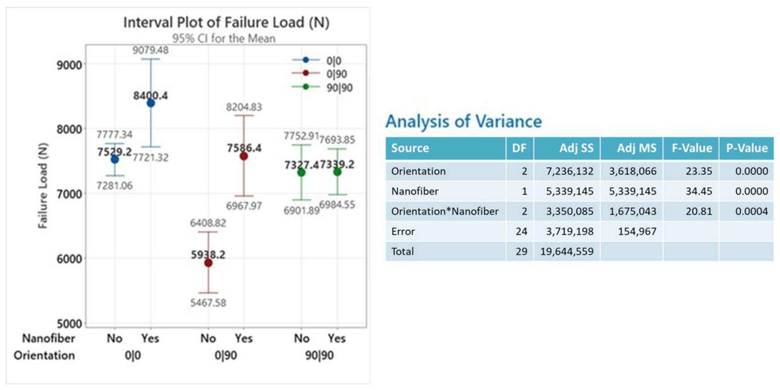
| Categorical Factor | # of Levels | Levels |
|---|---|---|
| Orientation | 3 | (0|0)–(0|90)–(90|90) |
| Nanofiber | 2 | No–Yes |
| Joint Interface Notation ANOVA Factorial Configurations [Orientation and Nanofiber] | ||||||
|---|---|---|---|---|---|---|
| (0|0) [(0|0) & No] | (0|X|0) [(0|0) & Yes] | (90|90) [(90|90) & No] | (90|X|90) [(90|90) & Yes] | (0|90) [(0|90) & No] | (0|X|90) [(0|90) & Yes] | |
| Parameters | Max_Load | Max_Load | Max_Load | Max_Load | Max_Load | Max_Load |
| Unit | (N) | (N) | (N) | (N) | (N) | (N) |
| (a) | 7649 | 7492 | 6752 | 7323 | 5950 | 7028 |
| (b) | 7302 | 8840 | 7283 | 7801 | 6496 | 7071 |
| (c) | 7599 | 8812 | 7519 | 7161 | 5433 | 8031 |
| (d) | 7758 | 8370 | 7606 | 7356 | 5961 | 7999 |
| (e) | 7338 | 8488 | 7477 | 7055 | 5851 | 7803 |
| Average | 7529 | 8400 | 7327 | 7339 | 5938 | 7586 |
| std. dev. | 217 | 547 | 343 | 286 | 379 | 498 |
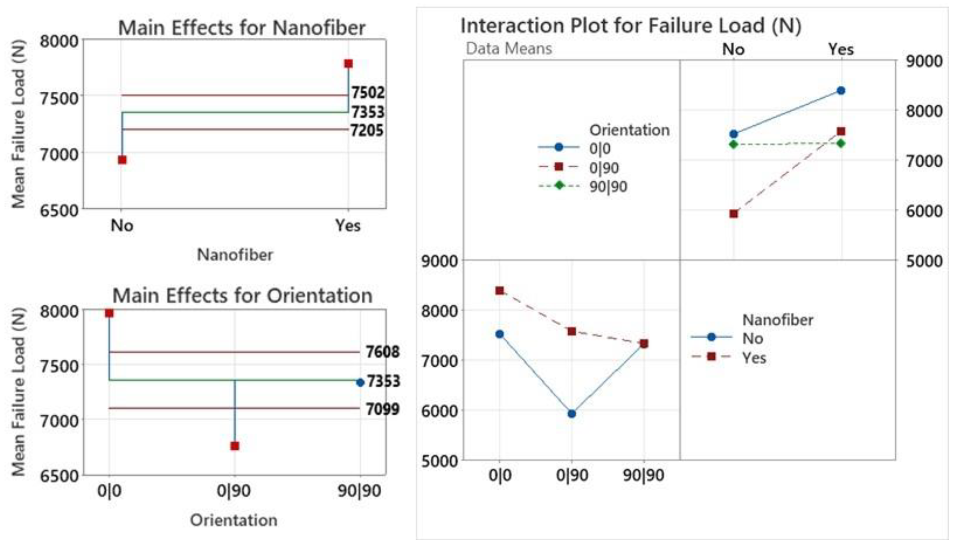
| Configuration | Failure Load (N) | % Strength Change | Key Effects of Nanofibrous Interlayers |
|---|---|---|---|
| (0|X|0) vs. (0|0) | 8400 vs. ~7500 | 12% | Increased 0/0 and 0/90 mode II delamination resistance; delayed crack coalescence due to excess resin blocks |
| (90|X|90) vs. (90|90) | ~7500 vs. ~7500 | 0% | No suppression of dominant transverse failure modes, especially at yarn interfaces |
| (0|X|90) vs. (0|90) | ~7500 vs. ~6000 | 25% | Most effective toughening; blocked crack jumps, and at yarn intersections, restored strength to (0|0)/(90|90) levels |
Disclaimer/Publisher’s Note: The statements, opinions and data contained in all publications are solely those of the individual author(s) and contributor(s) and not of MDPI and/or the editor(s). MDPI and/or the editor(s) disclaim responsibility for any injury to people or property resulting from any ideas, methods, instructions or products referred to in the content. |
© 2025 by the authors. Licensee MDPI, Basel, Switzerland. This article is an open access article distributed under the terms and conditions of the Creative Commons Attribution (CC BY) license (https://creativecommons.org/licenses/by/4.0/).
Share and Cite
Abdul Raheman, A.B.; Bilge, K.; Papila, M. Effects of Nanofiber Interleaving on the Strength and Failure Behavior of Co-Cured Composite Joints with Fiber Orientation Mismatch. J. Compos. Sci. 2025, 9, 285. https://doi.org/10.3390/jcs9060285
Abdul Raheman AB, Bilge K, Papila M. Effects of Nanofiber Interleaving on the Strength and Failure Behavior of Co-Cured Composite Joints with Fiber Orientation Mismatch. Journal of Composites Science. 2025; 9(6):285. https://doi.org/10.3390/jcs9060285
Chicago/Turabian StyleAbdul Raheman, Abdul Bari, Kaan Bilge, and Melih Papila. 2025. "Effects of Nanofiber Interleaving on the Strength and Failure Behavior of Co-Cured Composite Joints with Fiber Orientation Mismatch" Journal of Composites Science 9, no. 6: 285. https://doi.org/10.3390/jcs9060285
APA StyleAbdul Raheman, A. B., Bilge, K., & Papila, M. (2025). Effects of Nanofiber Interleaving on the Strength and Failure Behavior of Co-Cured Composite Joints with Fiber Orientation Mismatch. Journal of Composites Science, 9(6), 285. https://doi.org/10.3390/jcs9060285