Article

The In-Plane Compression Response of Thermoplastic Composites: Effects of High Strain Rate and Type of Thermoplastic Matrix

by
Svetlana Risteska
1,2,*,
Marco Peroni
3,
Sara Srebrenkoska
4,
Vineta Srebrenkoska
2,
Tatjana Glaskova-Kuzmina
5 and
Andreas Hornig
6,7
1
Laminati kom D.O.O., Aleksandar Makedonski 132, 7500 Prilep, North Macedonia
2
Faculty of Technology, Goce Delcev University, Krste Misirkov 10-A, P.O. Box 201, 2000 Stip, North Macedonia
3
Joint Research Centre Directorate E—Space, Security & Migration, Via E. Fermi 2749, 21027 Ispra, Italy
4
Faculty of Mechanical Engineering, Goce Delcev University, Krste Misirkov 10-A, P.O. Box 201, 2000 Stip, North Macedonia
5
Faculty of Science and Technology, University of Latvia, Jelgavas 3, LV-1004 Riga, Latvia
6
Institute of Lightweight Engineering and Polymer Technology, TUD Dresden University of Technology, Holbeinstr. 3, 01307 Dresden, Germany
7
Department of Engineering Science, University of Oxford, Parks Road, Oxford OX1 3PJ, UK
*
Author to whom correspondence should be addressed.
J. Compos. Sci. 2025, 9(6), 293; https://doi.org/10.3390/jcs9060293
Submission received: 24 April 2025 / Revised: 26 May 2025 / Accepted: 4 June 2025 / Published: 7 June 2025
(This article belongs to the Special Issue Additive Manufacturing of Advanced Composites, 2nd Edition)

Abstract

:
Designing thermoplastic composites for particular uses requires understanding their dynamic mechanical behaviour, which affects how well they operate in practical settings. The Split Hopkinson pressure bar (SHPB) test allows for evaluating these materials’ responses to high strain rates. In this study, an in-situ laser-assisted fibre placement (LAFP) machine has been utilised to produce laminate composites with varied designs, i.e., different angles of layers [0/45/–45/90]4s, using three types of thermoplastic tapes (UD-CF/PPS, UD-CF/PEEK, and UD-CF/PEKK). Using a servo-hydraulic testing machine and SHPB apparatus, we have examined the dynamic compressive behaviour of thermoplastic laminate composites with various matrices (PPS, PEEK, and PEKK) in in-plane directions and at strain rates of approx. 0.001, 0.1, 10, 800, 1800/s. Experimental results indicate that the type of thermoplastic matrix and strain rate significantly affect how the laminate composites behave. The in-plane compressive strength and modulus increase approximately linearly with the strain rate. According to the fracture of morphological pictures, the main failure mechanism of all three types of specimens is shear failure under in-plane compression loads, which is followed by delamination and burst.

1. Introduction

The strain rate can influence the stress–strain behaviour of FRP composite materials. Typically, the stiffness and strength increase with increasing applied strain rate. The anisotropic behaviour of FRP composite materials requires more tasks to measure all material parameters at high strain rates [1,2]. Standard test machines use strain rates up to 0.1/s, the process is considered isothermal, and inertia forces can be ignored. Above 0.1/s, inertial force must be considered in the experimental setup and the test, and for this, specialised equipment is used.
The SHPB is the preferred method from 200/s and up to 104/s, depending on the test material [3]. A list of test methods sorted by test type is given in Table 1. Reviews of FRP material testing at a high strain rate showed that the SHSB and the high-speed servo-hydraulic test machine were the preferred methods for testing FRP composite materials [4,5,6]. Combining these methods covers a strain rate regime from 0.1 to more than 1000/s. Further, these are also the standardised methods for testing metallic materials [7,8,9]. The car industry has mainly driven the standardisation of high-strain rate testing of metallic materials in the high-speed servo-hydraulic test machine [7,10,11,12,13,14].
Among the several techniques to achieve high strain rates for tests, the split-Hopkinson pressure bar testing is often used for composite materials [15,16,17,18,19,20,21,22,23,24,25,26,27], where both the specimen stress-time and the specimen strain-time response are calculated from the strain waves measured on the bars. Additionally, high-speed camera technology with high resolution allows the application of optical and contactless strain field measurement techniques, such as digital image correlation (DIC), to obtain accurate data reduction possibilities and more information on the distribution of strain over the specimen surface, which will be later employed in the dynamic material characterisation [11,28,29,30].
Comparing the obtained values for the mechanical properties calculated under the quasi-static and dynamic regimes, it is found that the PPS/Carbon Fibre Composite [31] exhibits a strain rate-insensitive mechanical behaviour concerning the strain rates applied. At the same time, the PPS/Glass Fibre Composite is strain rate dependent, which means enhancement of mechanical properties when the strain rate increases. Compressive strength increases by 38%, failure strain increases by 21%, and Young’s modulus increases by 23%.
This work focused on establishing robust experimental test methods with the high-speed servo-hydraulic test machine and the SHPB test rig used in compression. A high-speed servo-hydraulic test machine is used in material testing, structural testing, and component analysis. It combines a servo-controlled hydraulic system with a high-speed response to simulate dynamic loading conditions such as impacts, vibrations, and rapid stress changes. These machines test the performance of materials, components, and structures under high-speed, dynamic, or fatigue loading conditions. The specimen is deformed in either tension or compression by moving the piston rod [1,32]. The SHPB is based on techniques developed by Bertram Hopkinson in 1914 to study wave propagation in long elastic bars [1,32]. The method was later used by Davis and Hunter [33] and Kolsky et al. [34] to create the SHPB. The SHPB relies on a single elastic wave to load the specimen and avoids the oscillations in load measurements from the high-speed servo-hydraulic test machine. The original SHPB was designed for compression testing but was later extended to tension, torsion, multi-axial, and three-point bending tests.
The compressive rate and temperature dependence were investigated for short-fibre and hybrid carbon fibre PEEK composite materials manufactured through compression moulding [35,36,37]. In the study [37], both materials showed a clear strain rate dependence, with an increased strain rate leading to an increased compressive strength due to reduced fracture time, allowing for less matrix cracking before failure through matrix shearing. In the high-temperature quasi-static case, the strength was dramatically reduced by 64% due to the debonding of the UD reinforcement. The study shows the suitability of hybrid composites for impulsive applications and provides material parameters for the future design of composite structures subjected to impact events [37]. A dynamic tensile experiment was performed on a rectangular specimen of non-crimp fabric (NCF) thermoplastic composite T700 carbon/polyamide 6.6 specimens using a split Hopkinson pressure (Kolsky) bar (HPB). Tests were with 700, 1400, and 2100/s strain rates, and the tensile strength increases were 3.5, 24.2, and 45.1%, respectively, with strain rate [38]. References [39,40,41,42,43] present an experimental study of the effect of strain rate on the compressive properties of neat resin and the matrix-dominated tensile, compressive, and shear properties of a carbon-fibre-reinforced thermoplastic composite. Experiments were performed using a dynamic mechanical analysis at different frequencies to measure the strain-rate-dependent elastic properties of the polymer. The results show that strength and toughness decrease with increased strain rate.
The SHPB test is an excellent tool for evaluating the dynamic behaviour of composite materials, including thermoplastic polymers like Polyphenylene Sulfide (PPS), Polyetheretherketone (PEEK), and Polyetherketoneketone (PEKK). These materials are used in various applications, especially in industries that require high-performance materials capable of withstanding dynamic and high-strain rate conditions, such as aerospace, automotive, and biomedical industries. When used for composite materials, SHPB tests can provide valuable insights into their dynamic mechanical properties—such as stress–strain behaviour, failure modes, and strain rate sensitivity—under conditions similar to real-world dynamic loading scenarios. The dynamic response of composite materials is often more complex than that of pure polymers or metals, as they involve interactions between the matrix material and the reinforcement (e.g., fibres or particles).
In this paper, the evolution of the dynamic properties of LATP thermoplastic composites with strain rate is investigated. The effects of strain rate on the in-plane dynamic mechanical properties and failure mechanisms of thermoplastic composites are studied. High-strain-rate in-plane compression tests for three kinds of matrix composites (CF/PEEK, CF/PPS and CF/PEKK) were conducted over a wide range of strain rates (0.001–1800/s). This study is helpful in comprehensively understanding the dynamic mechanical properties of the thermoplastic matrix at LATP thermoplastic composites and guiding their engineering application.
In in-plane compression, the compressive forces are applied parallel to the plane of the laminate, which generally assesses how the material responds to forces acting along the laminate’s length or width. This test is valuable for components subjected to compressive forces along the plane of the laminate (e.g., fuselage or wing structures in aerospace). It is commonly used in designing parts that face continuous compressive loads in the plane, like beams or panels. In-plane compression tests are better suited for applications where continuous compressive forces are present in the plane of the laminate. The findings from this research are particularly relevant for applications in aerospace, automotive, and military industries where materials must endure high-impact forces.

2. Materials and Methods

2.1. Materials of Specimens

This work examined composite laminates made from CF/PEEK UD prepreg, CF/PEKK UD prepreg, and CF/PPS UD prepreg supplied by Suprem Company. The same type of carbon fibre (CF-AS4) was utilised in all three prepregs, but they have different matrices (PEEK, PEKK, and PPS). These UD prepregs have the same fibre weight percentage of 66 wt.%, have the same PAW 220 g/m2 and have the same thickness of 0.14 mm, but Table 2 provides an overview of the different characteristics of these UD prepregs. The 12″ UD prepreg tapes were cut to 1/4″ (6.35 mm) in width using a slitting machine. After that, they were positioned using the robotic arm and the LAFP method.

2.2. Manufacturing of Specimens

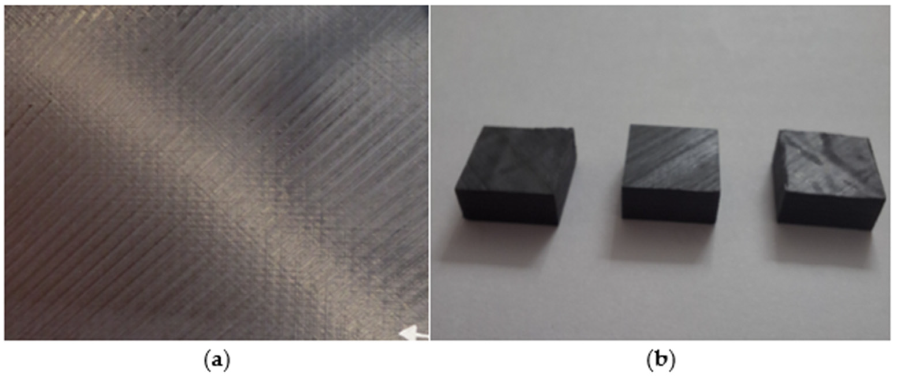
The LAFP process is an automated composite manufacturing technique often quoted for its potential ability to produce composite parts with an in-situ consolidation, which avoids an expensive time and energy-consuming step of post-consolidation [44,45,46,47,48,49,50,51,52,53,54,55,56]. However, to be competitive in this process, the quality of the fabricated parts needs to be ensured [44,45,46,50,51,52,53,54,55,56]. The laminate specimens for the experimental testing were created using the quasi-isotropic lay-up sequence [0/45/–45/90]4s and in-situ LAFP installation technology. The laminate specimens were made at the Institute of Advanced Composite Materials (IACR) in Prilep, North Macedonia. Figure 1 shows a schematic illustration of the manufacturing process. The LAFP process involved pulling thermoplastic prepreg tape from a spool via the feed and guide assembly. The tape was heated using a 3 kW laser heat source and an LDF series diode laser system (optic lens 33 × 43 mm and focal distance 200 mm) on its route to the consolidation roller. The tape was then placed on the mandrel/tool and consolidated with a roller with an outside diameter of 60 mm and four spools (4 × 6.35 mm). The LAFP technique laid up 32 layers of unidirectional prepregs, which were cured using the approved process conditions. Lay up speed (7–10 m/min), laser angle (15.8°) and consolidation pressure (400–500 N). Figure 2 shows a representation of the created laminate plate and the prepared samples for testing.
The thickness of cross-ply composite laminates is 4.5 mm, and these laminates have a void content (<3%) according to standard ASTM D2734 [57] and low moisture absorption according to standard ASTM D5229 [58].
To perform high-strain-rate compression testing, laminate specimens of 10 mm (length) × 10 mm (width) × 4.5 mm (thickness) were cut from laminate plates with a diamond saw. The specimen’s faces were polished to ensure parallel loading edges. To eliminate size effects on the impact testing, the specimens in all tests were the same size.
Figure 3 shows the specimens prepared for the in-plane compression test and the loading directions. Table 3 shows the assignation of the specimens and the related strain rates used in our investigations for each strain rate after three repetitions. A total of 45 specimens were tested for all five speeds and all three matrices and repeated three times.

2.3. Machine for Testing

FRP composite materials are highly orthotropic, which complicates the specimen design, so the standards for metallic materials cannot be used as direct guidelines for designed high-strain rate testing of FRP composite materials, and modification has to be applied. The servo-hydraulic testing machine and SHSB were provided by HopLab Laboratory of Joint Research Centre—Ispra, Italy, as shown in Figure 4.
The experiments were conducted at high strain rates representing dynamic loading conditions. These are typically much higher than the strain rates encountered in normal service conditions. The goal is to understand how the composite behaves under rapid deformation, such as during an impact event.

2.3.1. Servo-Hydraulic Testing Machine

Using a servo-hydraulic testing machine to characterise the mechanical properties of PEEK, PPS, and PEKK composites under static and quasi-static loading conditions provides a comprehensive understanding of their strength, stiffness, failure modes, and fatigue behaviour. The precision and versatility of servo-hydraulic testing machines enable the testing of these advanced materials under various mechanical conditions, helping optimise designs for reliability, durability, and performance. In this work, for small velocity (0.01, 1, 100 mm/s), a servo-hydraulic testing machine was used with a max load of 200 kN, max velocity of 200 mm/s, strain-gauge load cell, tempo sonics displacement sensors, and control system Elsa REC (Figure 4a).
For velocities 0.01 and 1 mm/s, PCO edge 5.5 camera and Veritas Constellation 120 lamps were used. For velocity V 100 mm/s, the following were used: NI USB-6366 acquisition board, ultra-high speed laser displacement sensors Keyence LK-G5000 and sensor head LK-H157, piezoelectric load cell Kistler 9106A, Charge amplifier Kistler 5015, High-speed camera IDT OS8-S3 and Veritas Constellation 120 lamps from Keyence Corporation of America (Itasca, IL, USA).

2.3.2. SHPB for High Strain Rate Testing

The SHPB is a widely used experimental setup for investigating the dynamic response of materials to high strain rates. It is especially useful for studying the mechanical behaviour of materials under conditions of high strain rate, such as those encountered in impact, crash, and blast events. The apparatus is named after its inventors, Bertram Hopkinson and John Hopkinson, who developed the basic concepts in the early 20th century [59,60,61,62,63]. The SHPB apparatus is based on the principle of stress waves propagating through a material. The specimen is placed between the ends of two straight bars, the incident bar and the transmitted bar. A stress wave is created at the end of the incident bar, propagating through the bar toward the specimen.
The SHPB setup uses strain gauges or other sensors on both the incident and transmission bars to measure the strain waves generated by the impact. These signals are processed to determine the stress–strain response of the material under high strain rates. In these tests from this work, the dynamic compression tests for velocities 8000 mm/s and 18,000 mm/s were performed with the SHPB (as shown in Figure 4b,c) apparatus with maraging 300 bars Ø 25mm (striker 2 m, input bar 2 m and output bar 4 m), Ohmic and semiconductor strain-gages, strain gage amplifier EFS SGA02 high-speed (cut-off frequency of 500 kHz) and fast transient recorder GAGE CSE8482-H2 (sample-rate 10 MHz). The specimen was sandwiched between the incident bar and the transmission bar.

3. Results

3.1. Compression Tests

3.1.1. Compressive Testing by Servo-Hydraulic Testing Machine

The samples were tested at various strain rates of loading, ranging from low to high, with the impact velocity changing. The strain rates 0.001/s, 0.1/s, and 10/s are crucial because they measure the speed at which the laminate is compressed during testing. Strain rate plays a significant role in how materials behave under stress. A low strain rate (0.001/s) means the material is compressed slowly, while a high strain rate (10/s) is compressed quickly. This could reveal how different composites handle varying stress over time, mimicking real-life conditions involving different loading speeds (e.g., fast crashes and slow compression in a controlled environment).
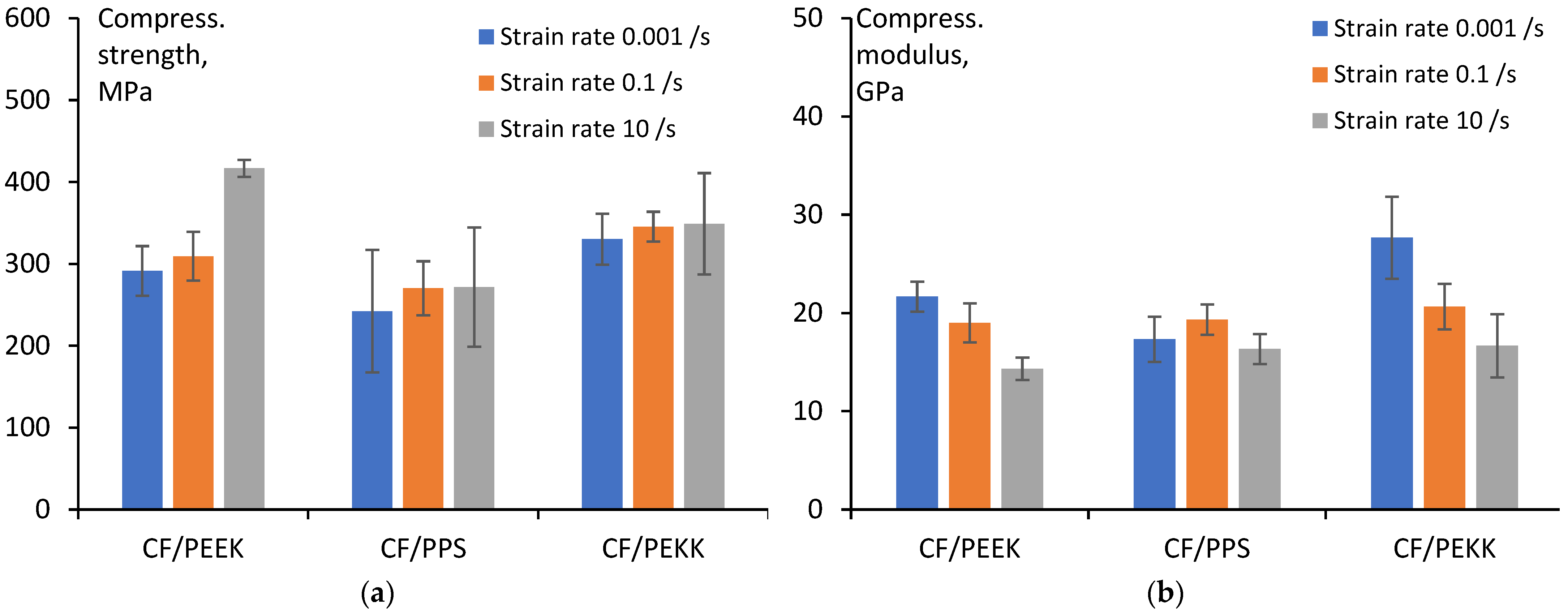
Figure 5 illustrates the representative curves of only one of the three repeat samples used for each polymer matrix in the laminate at different strain rates given by the servo-hydraulic testing machine. The composite samples with different polymer matrices (PPS, PEEK, and PEKK) behave differently when subjected to various strain rates. However, Figure 6 shows the average values in compressive strength/modulus and standard deviation from the three repeated tests for each laminate sample with different polymer matrices (PEEK, PPS, PEKK) and with different strain rates (0.001/s; 0.1/s; 10/s) from the servo-hydraulic machine.

3.1.2. SHPB Apertures for High Strain Rate Testing (800/s and 1800/s)

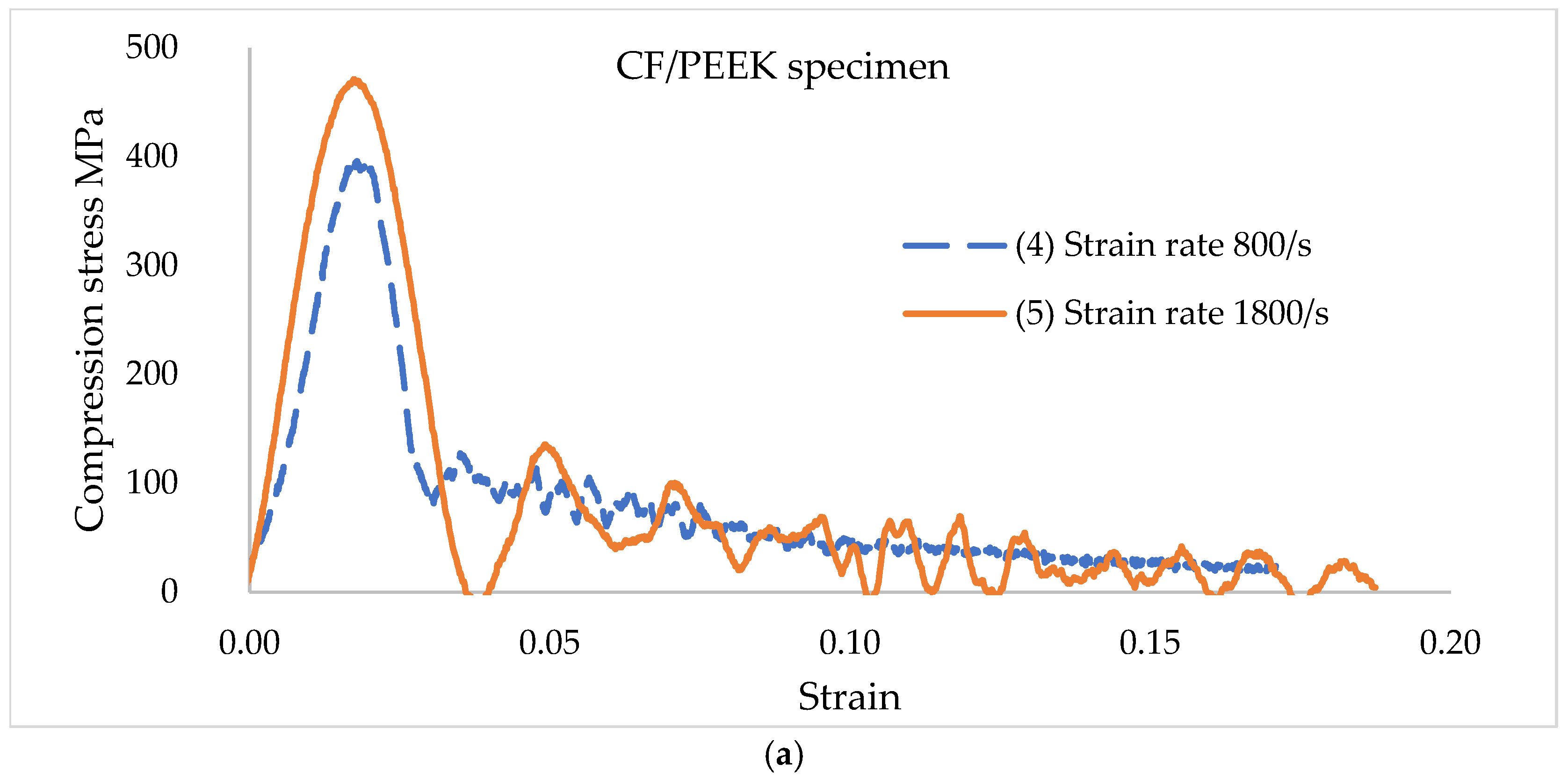
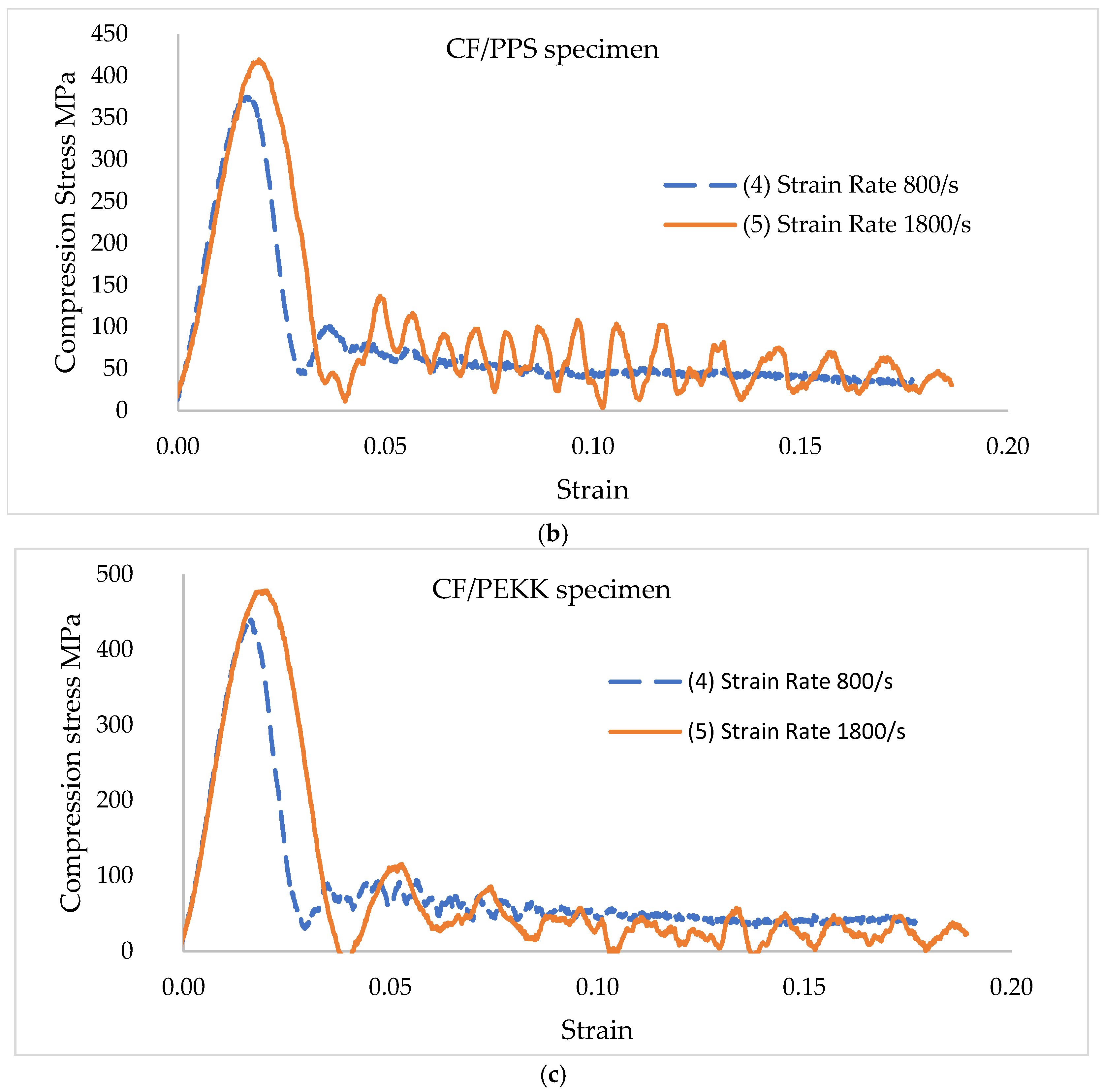
The compressive samples were mounted between flat bar ends, and a small amount of silicon grease was used to secure the samples. A cardboard pulse shaper mounted at the interface between the striker and the input bar was used to control the rise time of the stress wave. Two different strain rates were imposed, 800 and 1800/s.
Figure 7 illustrates only one of the three specimens used for each polymer matrix in the laminate at different strain rates. However, Figure 8 presents the results of the compression strength/modulus and standard deviation from the three repeated tests for each laminate sample with different polymer matrices (PEEK, PPS, PEKK) and with different strain rates (800/s; 1800/s) from SHPB apertures.

4. Discussion

4.1. Influence of All Strain Rates on Composite Samples

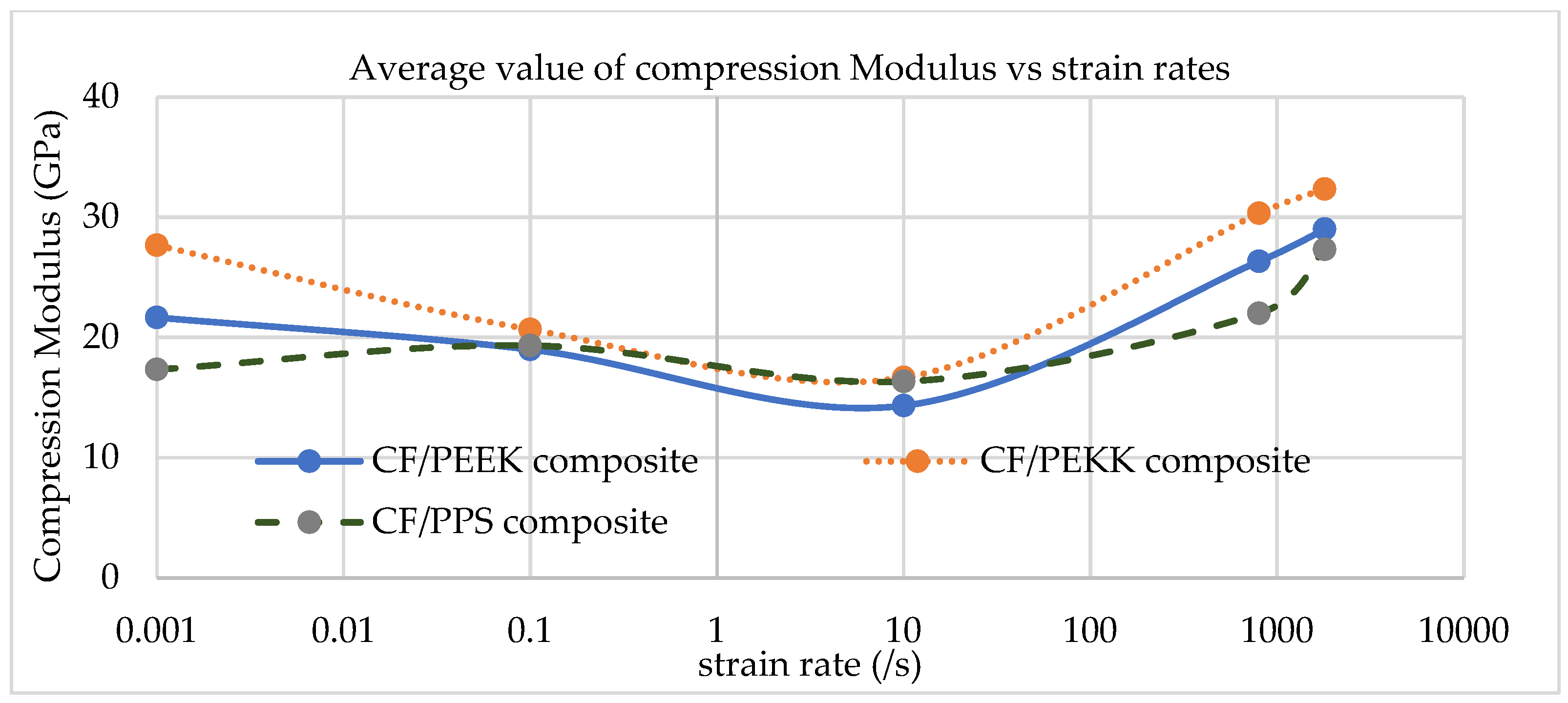
In order to see the influence of all strain rates and composite samples tested in this paper, due to the significant difference in strain rates from 0.001/s to 1800/s, the strain rates are processed in logarithms, and the diagrams are given in Figure 9 and Figure 10.
Figure 9 compares the impact of different polymer matrices on the average compression strength of the laminate samples across varying strain rates. It suggests that the type of polymer matrix used in the composite laminates plays a significant role in how the material behaves under different strain rates.
Figure 9 shows that the composite sample with PPS shows the lowest compression strength, meaning it deforms easily under slow compression. This could suggest that PPS is less rigid or less deformation-resistant than PEEK and PEKK. The composite sample with PPS has the lowest compression resistance even at higher strain rates, suggesting it does not gain significant strength when compressed quickly. This could be due to the polymer’s molecular structure or how it interacts with the reinforcement fibres in the composite.
The PPS-based composite laminates have the lowest compression value for speeds up to 20 mm/s (first crossing—strain rate 2/s), followed by PEEK-based composites, while PEKK-based composites have the highest value. This might be due to PEKK’s higher molecular weight and crystalline structure, making it more resistant to deformation under low-speed compression. At strain rates above 2/s, the performance of PEKK composites starts to decline compared to PEEK. This suggests that, while PEKK performs well at lower strain rates, its resistance to high-speed compression is less robust than PEEK, likely due to differences in polymer properties like molecular flexibility and thermal stability. The composite laminates with a PEEK matrix have the highest value at a greater strain rate of 2/s–500/s (second crossing 500/s), while the samples with a PPS matrix have the lowest value once more. At strain rate over 2/s, PEEK laminates continue to offer superior performance compared to PPS and PEKK laminates. This may be because PEEK has superior thermal stability and a more robust molecular structure, allowing it to retain its integrity even at higher compression speeds with a servo-hydraulic testing machine. However, for SHSB tests, the PEKK composite samples are the strongest compared to PPS and PEEK laminates above 500/s up to 1800/s.
The results indicate that PEEK and PEKK matrices offer better performance in resisting compression at high strain rates, suggesting they might be more suitable for applications where the material experiences high-speed loading or impact forces. In contrast, PPS might not be as resilient under these conditions.
Figure 10 shows that the compression modulus for a strain rate from 0.1/s to 10/s decreases at all three composites (CF/PPS, CF/PEEK, and CF/PEKK). All three composite materials (CF/PPS, CF/PEEK, and CF/PEKK) exhibit strain rate sensitivity, meaning their mechanical properties (e.g., strength, modulus) increase as the strain rate increases [64,65,66,67]. SHPB tests can quantify this effect, which is crucial for applications where materials are subject to dynamic loading, such as crash simulations or impact testing [68,69,70]. For example, CF/PEEK composites might exhibit enhanced performance (higher yield strength) at high strain rates compared to their behaviour in quasi-static conditions.
The findings in the paper suggest that the choice of polymer matrix directly impacts the deformation behaviour and structural integrity of composite materials under different conditions. By carefully selecting the appropriate matrix, manufacturers can tailor the material’s performance to meet the specific requirements of their application for slow compression, fast compression, or a mix of both. Design engineers often choose composite materials based on the application’s expected environmental conditions, load-bearing requirements, and specific performance needs. This study provides critical insights: PPS is less suited for high-speed or heavy-duty applications where materials experience high strain rates and heavy loads. PEKK is ideal for slower, more controlled applications where resistance to deformation at moderate speeds is essential. PEEK is versatile, performing well at various strain rates, making it an excellent choice for environments that experience mixed loading conditions.

4.2. Failure Mode and Damage Mechanism

4.2.1. SEM and Optical Images

Using optical images (partly only for samples a11, b11 and c11 present in the paper in Figure 11), it is observed that all composite structures have the same summary, which are produced with LAFP technology before testing, have a good interface fibre/matrix and a low percentage of voids below 3%.
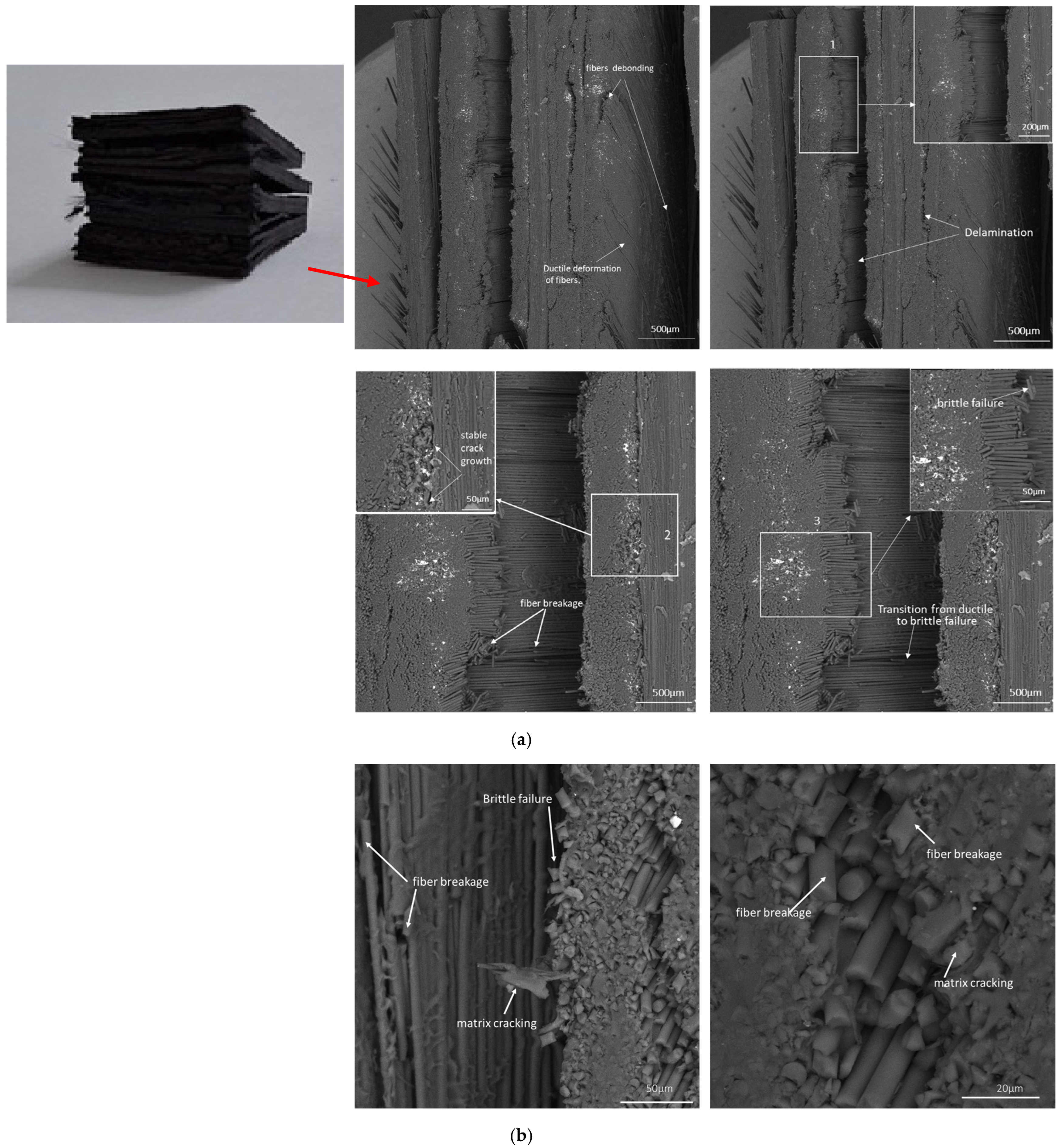
The SEM analysis of samples (Figure 12, Figure 13 and Figure 14) provides critical insights into the matrix dependency of damage mechanisms in thermoplastic composite laminates. As strain rate increases, the observed failure modes highlight the progressive transition from ductile to brittle failure. Fibre breakage (Figure 12 sample a11 PEEK matrix) is a dominant feature at strain rate 0.1/s, indicating that the fibres absorb most of the load before catastrophic failure. The multiple fracture locations (white dotted lines) suggest that stress concentrations developed at different points, leading to sequential failure rather than a single catastrophic break. The sharp, clean fracture surfaces of the fibres in SEM images indicate brittle failure, which becomes more pronounced at higher strain rates. This suggests that at extreme loading speeds, the energy absorption capacity of the composite reduces, causing fibres to fracture before significant plastic deformation can occur. The fibre breakage and fibre–matrix debonding (Figure 12 and Figure 14) is a significant damage mechanism observed in the same strain-rate samples with different matrix PEEK and PEKK. The presence of matrix cracking and delamination in sample c11 suggests that the interfacial strength between the matrix and the fibres plays a crucial role in resisting damage.
PEEK composites outperform PEKK and PPS, maintaining better load transfer even in extreme conditions. Fibre breakage-dominated failure (as seen in a11) suggests that high-strength applications (e.g., aerospace, ballistic protection) require composites with enhanced fibre toughness and interfacial bonding. The extensive delamination observed in c11, c21 highlights the need for optimised fibre-matrix adhesion to improve high-strain-rate performance.

4.2.2. Images from the DIC Camera During Testing

In composite materials, particularly those reinforced with fibres (like carbon or glass), the damage mechanisms that occur during loading can significantly affect the overall performance and strength of the material. In-plane compression tests are the most effective for detecting specific damage mechanisms, such as matrix shear failure and fibre micro-buckling.
The images obtained by the DIC camera during the testing of all composite materials were used in this study for the crack and failure analysis of the samples. Due to the large number of images, only images from six specimens (from 45) are presented in the paper (see Figure 15 sample a31; Figure 16 sample a41; Figure 17 sample b31; Figure 18 sample b41; Figure 19 sample c31 and Figure 20 sample c41).
During an in-plane compression test, the composite is subjected to compressive forces along the fibre-reinforced composite layers. This test can lead to matrix shear failure because the compressive load directly affects the shear stresses within the matrix material. If the shear strength of the matrix is exceeded, shear failure can occur, typically starting at the fibre–matrix interface or within the matrix itself. This often manifests as localised cracking or the formation of shear bands in the matrix. During an in-plane compression test, the compressive forces cause the fibres to experience compressive stress. If the fibres are imperfectly aligned or if there are flaws in the material, they can undergo buckling or local failure due to compressive stresses. Applying compressive forces along the composite plane can lead to these critical failure modes, which can significantly impact the durability and performance of composite structures.

4.2.3. Failure Mechanism Evolution Across Strain Rates

The composite exhibits progressive damage at low to moderate strain rates (0.001/s–10/s), with matrix cracking and fibre pull-out being dominant. The fibre–matrix interface fails completely at high strain rates (800/s–18,000/s, SHPB testing), leading to widespread delamination/burst and fibre fragmentation. All failure mechanism evolution across strain rates according to camera and microscope images is present at Table 4.
PPS exhibits higher matrix cracking at low strain rates (0.001/s–0.1/s) due to its relatively lower toughness and interfacial bonding. The stress is distributed more in the matrix, leading to early microcracking and debonding. PEEK displays ductile failure, with matrix yielding and controlled crack propagation. The fibre–matrix interface remains mostly intact, allowing efficient stress transfer. However, PEKK is similar to PEEK but exhibits slightly higher stiffness and better thermal stability, which can reduce microcracking under moderate loading conditions.
At intermediate strain rates (10/s), PPS shows increased fibre–matrix debonding and matrix cracking, leading to a more brittle failure mode. The matrix begins to lose its ability to deform plastically. PEEK retains some ductility, but stress concentrations can initiate microvoids at the interface, increasing the risk of fibre pull-out. Moreover, PEKK tends to have better energy absorption than PPS, with crack propagation occurring more slowly due to its tougher nature. However, the failure mode begins to transition towards brittle behaviour. PPS failure is predominantly brittle at high strain rates (800/s–1800/s), characterised by sudden fibre breakage and severe delamination. The lower interfacial strength results in significant fibre pull-out, reducing overall strength. PEEK experiences a transition to brittle failure, where delamination and matrix fragmentation become more pronounced. Fibre failure is also observed at this stage. PEKK is similar to PEEK but maintains higher toughness at slightly higher strain rates before exhibiting severe delamination. Its ability to withstand thermal and mechanical stress may delay catastrophic failure compared to PPS.
The compatibility between resin and fibre significantly influences high-strain behaviour in composite materials; good compatibility ensures efficient stress transfer at the interface, reducing the likelihood of debonding or micro-cracking under high strain, while poor compatibility can lead to premature failure and reduced mechanical performance. PEEK and PEKK show similar strain rate behaviour, likely because they both form relatively strong and stable bonds with the carbon fibres, and their molecular structures allow for consistent load transfer even under rapid deformation. In contrast, PPS at higher rates, according to poor fibre–matrix interaction, can result in early debonding, localized failures, or less energy absorption, which makes its mechanical response quite different from PEEK and PEKK.
Pictures of failed specimens (as referenced in the study) reveal that strong fibre–matrix bonding results in cohesive failure modes (shear and delamination), while weaker bonding (as in PPS composites) may show more interfacial debonding and fibre pull-out, indicating less efficient load transfer. The differences in macrostructure after high-strain-rate testing visually support the argument that fibre–matrix compatibility governs the failure mode and strain rate response. The fibre–matrix bond is a decisive factor in the strain rate response of thermoplastic composites. Enhanced compatibility leads to improved strength, toughness, and strain rate sensitivity, as clearly demonstrated by the superior performance of PEEK and PEKK over PPS in the referenced study.

5. Conclusions

In this paper, a high-strain-rate compression experiment was conducted at various strain rates (0.001–1800/s) and various thermoplastic matrices (PEEK, PPS, PEKK) to investigate the loading conditions on the mechanical properties and failure mechanism of CF/PEEK, CF/PPS and CF/PEKK composites.
The results can be summarised as follows:
  • The stress–strain curves steepen with the strain-rate increase, which is further reflected by the quasi-linear increase in dynamic strength and modulus.
  • Thermoplastic composites show significant strain rate sensitivity. At low to moderate strain rates (0.001–0.1/s), PEKK composites exhibit the highest compression strength, while PPS composites perform the weakest.
  • At medium strain rates (10/s), PEEK composites outperform PEKK and PPS, showing the highest compression strength and best resistance to dynamic loading.
  • At high strain rates (800–1800/s), PEKK-linked composites again outperform PEEK and PPS, showing the highest compressive strength.
  • PPS consistently demonstrates the lowest strength and highest susceptibility to fibre–matrix debonding and brittle failure across all strain rates.
  • The results can guide the development of more efficient composite materials and improve the design of components that must perform under dynamic loading.

Author Contributions

Conceptualisation, S.R. and M.P.; methodology, M.P.; software, M.P. and S.R.; validation, S.R., S.S. and V.S.; formal analysis, S.R. and M.P.; investigation, S.R., S.S. and V.S.; resources, S.R. and T.G.-K.; data curation, S.R., T.G.-K. and A.H.; writing—original draft preparation, S.R. and V.S.; writing—review and editing, T.G.-K. and A.H.; visualisation, S.R.; supervision, T.G.-K. and A.H., project administration, S.R., S.S. and V.S.; funding acquisition T.G.-K. and A.H. All authors have read and agreed to the published version of the manuscript.

Funding

This research received no external funding.

Data Availability Statement

Data is contained within the article. The data presented in this study are available from the corresponding author upon request.

Acknowledgments

The composite laminate production was carried out in the Institute for Advanced Composites and Robotics Prilep (North Macedonia). The mechanical analysis was performed at the company Joint Research Centre Directorate E—Space Security & Migration Via E. Fermi, 2749 21027 Ispra (VA), Italy, but the SEM analyses were performed at the Faculty of Technology, Goce Delcev University Stip (North Macedonia). These experiments are part of a HISTRATE—COST Action CA21155. The authors are very grateful to all these institutions for their support in realising this research project.

Conflicts of Interest

Author Svetlana Risteska is employed by the company Laminati Kom. D.O.O. The authors declare that the research was conducted in the absence of any commercial or financial relationships that could be construed as a potential conflict of interest.

Nomenclature

List of used abbreviations
AbbreviationDescription
SHPBSplit Hopkinson pressure bar
FRPFibre-reinforced polymeric
LAFPLaser-assisted automated fibre placement
PAWPrepreg areal weight
PEEK/PEKKPolyether ether ketone/Polyetherketoneketone
PPSPolyphenylene sulfide
CFCarbon fibre
UD prepregUnidirectional prepreg
SEMScanning electron microscope
DICDigital Image Correlation

References

  1. Eriksen, R.N.W. High Strain Rate Characterisation of Composite Materials. DTU Mechanical Engineering. DCAMM Special Report No. S179, 2014. Available online: https://backend.orbit.dtu.dk/ws/files/113893873/High_Strain_Rate_characterisation.pdf (accessed on 1 January 2020).
  2. Kolsky, H. An Investigation of the Mechanical Properties of Materials at very High Rates of Loading. Proc. Phys. Soc. Sect. B 1949, 62, 676. [Google Scholar] [CrossRef]
  3. Meyers, M.A. Dynamic Behavior of Materials; John Wiley & Sons, Inc.: Hoboken, NJ, USA, 1994; pp. 323–447. [Google Scholar]
  4. Sierakowski, R.L. Strain rate effects in composites. Appl. Mech. Rev. 1997, 50, 741–761. [Google Scholar] [CrossRef]
  5. Jacob, G.C.; Starbuck, J.M.; Fellers, J.F.; Simunovic, S.; Boeman, R.G. Strain Rate Effects on the Mechanical Properties of Polymer Composite Materials. J. Appl. Polym. Sci. 2004, 94, 296–301. [Google Scholar] [CrossRef]
  6. Barré, S.; Chotard, T.; Benzeggagh, M.L. Damage mechanisms in low energy impact of glass–fibre–reinforced thermoplastic. Compos. Part A Appl. Sci. Manuf. 1996, 27, 1169–1181. [Google Scholar] [CrossRef]
  7. Wood, P.K.C.; Schley, C.A. Strain Rate Testing of Metallic Materials and Their Modelling for Use in CAE Based Automotive Crash Simulation Tools: Recommendations and Procedures; iSmithers: Shrewsbury, UK, 2009; ISBN 978-1-84735-374-0. [Google Scholar]
  8. Zou, H.; Yin, W.; Cai, C.; Wang, B.; Liu, A.; Yang, Z.; Li, Y.; He, X. The out-of-plane compression behavior of cross-ply AS4/PEEK thermoplastic composite laminates at high strain rates. Materials 2018, 11, 2312. [Google Scholar] [CrossRef]
  9. Wang, S.; Wen, L.; Xiao, J.; Lei, M.; Liang, J. Influence of strain rate and temperature on mechanical properties of carbon woven-ply PPS thermoplastic laminates Under dynamic compression. Polym. Test. 2020, 89, 106725. [Google Scholar] [CrossRef]
  10. Wood, P.; Schley, C.A.; Smith, G.F.; Buckley, M. A new test procedure to validate dynamic tensile mechanical properties of sheet metals and alloys in light weight automotive crash applications. SAE Tech. Pap. 2008, 28, 0019. [Google Scholar] [CrossRef]
  11. Stasicki, B.; Charvat, A.; Faubel, M.; Abel, B. Visualization of laser-induced liquid micro-jet disintegration by means of high-speed video stroboscopy. In Proceedings of the 26th International Congress on High-Speed Photography and Photonics, Alexandria, VA, USA, 19–24 September 2004; Volume 5580. [Google Scholar] [CrossRef]
  12. Eriksen, R.N.W.; Berggreen, C.; Boyd, S.W.; Dulieu-Barton, J.M. Towards high velocity deformation characterisation of metals and composites using Digital Image Correlation. EPJ Web Conf. 2010, 6, 31013. [Google Scholar] [CrossRef]
  13. Bardenheier, R.; Rogers, G. Dynamic impact testing with servohydraulic testing machines. J. Phys. IV Fr. 2006, 134, 693–699. [Google Scholar] [CrossRef]
  14. Hamouda, A.M.S.; Hashmi, M.S.J. Testing of composite materials at high rates of strain: Advances and challenges. J. Mater. Process. Technol. 1998, 77, 327–336. [Google Scholar] [CrossRef]
  15. Hosur, M.V.; Alexander, J.; Jeelani, S.; Vaidya, U.K.; Mayer, A. High strain compression responses of affordable woven carbon/epoxy composites. J. Reinf. Plast. Compos. 2003, 22, 271–296. [Google Scholar] [CrossRef]
  16. Bandaru, A.K.; Chouhan, H.; Bhatnagar, N. High strain rate compression testing of intra-ply and inter-ply hybrid thermoplastic composites reinforced with Kevlar/basalt fibers. Polym. Test. 2020, 84, 106407. [Google Scholar] [CrossRef]
  17. Dash, K.; Sukumaran, S.; Ray, B.C. Effect of loading speed on deformation of composite materials: A critical review. J. Adv. Res. Manuf. Mater. Sci. Metall. Eng. 2014, 1, 1–22. Available online: https://dspace.nitrkl.ac.in/dspace/handle/2080/2126 (accessed on 3 June 2025).
  18. Brown, K.A.; Brooks, R.; Warrior, N.A. The static and high strain rate behavior of a commingled E-glass/polypropylene woven fabric composite. Compos. Sci. Technol. 2010, 70, 272–283. [Google Scholar] [CrossRef]
  19. Nemat-Nasser, S. Introduction to high strain rate testing. In ASM Handbook Volume 8 Mechanical Testing and Evaluation; ASM International: Novelty, OH, USA, 2000. [Google Scholar]
  20. Qian, X.; Wang, H.; Zhang, D.; Wen, G. High strain rate out-of-plane compression properties of aramid fabric reinforced polyamide composite. Polym. Test. 2016, 53, 314–322. [Google Scholar] [CrossRef]
  21. Woo, S.C.; Kim, T.W. High strain rate failure in carbon/Kevlar hybrid woven composites via a novel SHPB-AE coupled test. Compos. Part B Eng. 2016, 97, 317–328. [Google Scholar] [CrossRef]
  22. Gray, G.T., III. Classic split-Hopkinson pressure bar testing. In ASM Handbook Volume 8 Mechanical Testing and Evaluation; ASM International: Novelty, OH, USA, 2000. [Google Scholar]
  23. Gray, G.T., III; Blumenthal, W.R. Split-Hopkinson pressure bar testing of soft materials. In ASM Handbook Volume 8 Mechanical Testing and Evaluation; ASM International: Novelty, OH, USA, 2000. [Google Scholar]
  24. Chen, W.W.; Song, B. Split Hopkinson (Kolsky) Bar: Design, Testing and Applications; Springer: New York, NY, USA, 2011. [Google Scholar]
  25. Hou, J.P.; Ruiz, C. Measurement of the properties of woven CFRP T300/914 at different strain rates. Compos. Sci. Technol. 2000, 60, 2829–2834. [Google Scholar] [CrossRef]
  26. Gama, B.A.; Lopatnikov, S.L.; Gillespie, J.W., Jr. Hopkinson bar experimental technique: A critical review. Appl. Mech. Rev. 2004, 57, 223–250. [Google Scholar] [CrossRef]
  27. Reis, V.L.; Marini, L.F.; Donadon, M.V.; Dutra, T.A.; Baldo Junior, J.E.; Nunes de Mello, W.L. Experimental investigation on the influence of the geometry of carbon fiber specimen used in split Hopkinson pressure bar tests. In Proceedings of the 23rd ABCM International Congress of Mechanical Engineering, Rio de Janeiro, Brazil, 6–11 December 2015. [Google Scholar]
  28. Koerber, H.; Xavier, J.; Camanho, P.P.; Essa, Y.E.; Martín de la Escalera, F. High strain rate behaviour of 5-harness satin weave fabric carbon–epoxy composite under compression and combined compression–shear loading. Int. J. Solids Struct. 2015, 54, 172–182. [Google Scholar] [CrossRef]
  29. Jerabek, M.; Major, Z.; Lang, R.W. Strain determination of polymeric materials using digital image correlation. Polym. Test. 2010, 29, 407–416. [Google Scholar] [CrossRef]
  30. Ploeckl, M.; Kuhn, P.; Koerber, H. Characterization of unidirectional carbon fiber reinforced polyamide-6 thermoplastic composite under longitudinal compression loading at high strain rate. EPJ Web Conf. 2015, 94, 01041. [Google Scholar] [CrossRef]
  31. Ramirez, C.; Reis, V.; Opelt, C.; Santiago, R.; Almeraya, F.; Donadon, M.V.; Gaona, C.; Croche, R.; Baltazar, M.A. High strain rate characterisation of thermoplastic fiber-reinforced composites under compressive loading. In Fiber-Reinforced Plastic; Intech Open: London, UK, 2018. [Google Scholar] [CrossRef]
  32. Hopkinson, B. A method of measuring the pressure produced in the detonation of high explosives or by the impact of bullets. Proc. R. Soc. Lond. Ser. A 1914, 89, 411–413. [Google Scholar]
  33. Davies, R.M. A critical study of the Hopkinson pressure bar. Philos. Trans. R. Soc. Lond. Ser. A Math. Phys. Sci. 1948, 240, 375–457. [Google Scholar] [CrossRef]
  34. Kordas, P.D.; Lampeas, G.N.; Fotopoulos, K.T. Numerical Investigation of an Experimental Setup for Thermoplastic Fuselage Panel Testing in Combined Loading. Aerospace 2024, 11, 175. [Google Scholar] [CrossRef]
  35. Sitohang, R.D.R.; Grouve, W.J.B.; Warnet, L.L.; Koussios, S.; Akkerman, R. An experimental approach to reproduce in-plane fiber waviness in thermoplastic composites test coupons using a reverse forming method. J. Compos. Mater. 2022, 56, 561–574. [Google Scholar] [CrossRef]
  36. Samak, S.; Risteska, S.; Dukovski, V.; Trajkoski, S. Some experimental investigation of products from thermoplastic composite materials manufactured with robot and LAFP. Int. J. Eng. Res. Technol. 2020, 9, 1082–1088. [Google Scholar]
  37. Pheysey, J.; De Cola, F.; Pellegrino, A.; Martinez-Hergueta, F. Strain rate and temperature dependence of short/unidirectional carbon fibre PEEK hybrid composites. Compos. Part B Eng. 2024, 268, 111080. [Google Scholar] [CrossRef]
  38. Mohsin, M.A.A.; Iannucci, L.; Greenhalgh, E.S. On the dynamic tensile behaviour of thermoplastic composite carbon/polyamide 6.6 using split Hopkinson pressure bar. Materials 2021, 14, 1653. [Google Scholar] [CrossRef]
  39. Perry, J.I.; Walley, S.M. Measuring the effect of strain rate on deformation and damage in fibre-reinforced composites: A review. J. Dyn. Behav. Mater. 2020, 8, 178–213. [Google Scholar] [CrossRef]
  40. Mario, R.R. Experimental and Computational Micromechanics of Fiber-Reinforced Polymer Composites at High Strain Rate. Ph.D. Thesis, Universidad Politecnica de Madrid, Madrid, Spain, 2021. [Google Scholar]
  41. Ma, L.L.; Liu, F.; Liu, D.; Liu, Y. Review of Strain Rate Effects of Fiber-Reinforced Polymer Composites. Polymers 2021, 13, 2839. [Google Scholar] [CrossRef]
  42. Marina, P. Effect of Strain Rate on the Tensile, Compressive, and Shear Response of Carbon-Fiber-Reinforced Thermoplastic Composites. Ph.D. Thesis, Technische Universität München, München, Germany, 2019. [Google Scholar]
  43. Hosur, M.V.; Alexander, J.; Vaidya, U.K.; Jeelani, S. High strain rate compression response of carbon/epoxy laminate composites. J. Compos. Struct. 2001, 52, 405–417. [Google Scholar] [CrossRef]
  44. Risteska, S. Unidirectional carbon fiber reinforced thermoplastic tape in automated tape placement process. In Fiber-Reinforced Plastic; Intech Open: London, UK, 2021; pp. 1–16. [Google Scholar] [CrossRef]
  45. Ma, H.; Bandaru, A.K.; Weaver, P.M. The effect of laser assisted tape placement processing conditions on microstructural evolution, residual stress and interlaminar shear strength of carbon fibre/PEEK laminates. Compos. Part B Eng. 2024, 276, 111293. [Google Scholar] [CrossRef]
  46. Srebrenkoska, S.; Dukovski, V.; Risteska, S. Influence of the process parameters on laser-assisted automated tape placement process. Int. J. Eng. Res. Technol. 2020, 9, 638–644. [Google Scholar]
  47. Risteska, S.; Trajkovska Petkoska, A.; Samak, S.; Drienovsky, M. Annealing effects on the crystallinity of carbon fiber-reinforced polyether ether ketone and polyphenylene laminate composites manufactured by laser automatic tape placement. Mater. Sci. (Medžiagotyra) 2020, 26, 314–322. [Google Scholar] [CrossRef]
  48. Pourahmadi, E.; Ganesan, R.; Shadmehri, F. Effect of in-situ consolidation on the in-plane elastic moduli of Carbon/PEEK thermoplastic composites made by Automated Fiber Placement (AFP) process. In Proceedings of the 21st European Conference on Composite Materials (ECCM21), Nantes, France, 2–5 July 2024. [Google Scholar]
  49. Stelter, C.J.; Sreekantamurthy, T.; Hudson, T.B.; Grimsley, B.W. Thermal modelling of the in-situ consolidation of automated fiber placement of thermoplastic composites. In Proceedings of the Society for the Advancement of Material and Process Engineering (SAMPE), Long Beach, CA, USA, 20–23 May 2024. [Google Scholar] [CrossRef]
  50. Saffar, F.; Sonnenfeld, C.; Beauchêne, P.; Park, C.H. In-situ monitoring of the out-of-autoclave consolidation of carbon/poly-ether-ketone-ketone prepreg laminate. Front. Mater. 2020, 7, 195. [Google Scholar] [CrossRef]
  51. Thor, M.; Sause, M.G.R.; Hinterhölzl, R.M. Mechanisms of origin and classification of out-of-plane fiber waviness in composite materials—A review. J. Compos. Sci. 2020, 4, 130. [Google Scholar] [CrossRef]
  52. Celik, O.; Peeters, D.; Dransfeld, C.; Teuwen, J. Intimate contact development during laser assisted fiber placement: Microstructure and effect of process parameters. Compos. Part A Appl. Sci. Manuf. 2020, 134, 105888. [Google Scholar] [CrossRef]
  53. Baho, O.; Ausias, G.; Grohens, Y.; Férec, J. Simulation of laser heating distribution for a thermoplastic composite: Effects of AFP head parameters. Int. J. Adv. Manuf. Technol. 2020, 110, 2105–2117. [Google Scholar] [CrossRef]
  54. Croft, K.; Lessard, L.; Pasini, D.; Hojjati, M.; Chen, J.; Yousefpour, A. Experimental study of the effect of automated fiber placement induced defects on performance of composite laminates. Compos. Part A Appl. Sci. Manuf. 2011, 42, 484–491. [Google Scholar] [CrossRef]
  55. Hoang, M.D. Procedure for Making Flat Thermoplastic Composite Plates by Automated Fiber Placement and Their Mechanical Properties. Master’s Thesis, Concordia University Montreal, Montreal, QC, Canada, 2015. [Google Scholar]
  56. Feuillerat, L.; De Almeida, O.; Fontanier, J.C.; Schmidt, F. Effect of poly (ether-ether ketone) degradation on commingled fabrics consolidation. J. Compos. Part A 2021, 149, 106482. [Google Scholar] [CrossRef]
  57. ASTM Standard D 2734-11; Standard Test Methods for Void Content of Reinforced Plastics. ASTM International: West Con shohocken, PA, USA, 2011.
  58. ASTM Standard D5229-14; Standard Test Method for Moisture Absorption Properties and Equilibrium Conditioning of Polymer Matrix Composite Materials. ASTM International: West Con shohocken, PA, USA, 2014.
  59. Yang, Y.; Li, Q.; Qiao, L. Review of SHPB dynamic load impact test characteristics and energy analysis methods. Processes 2023, 11, 3029. [Google Scholar] [CrossRef]
  60. Pankow, M.; Attard, C.; Waas, A.M. Specimen size and shape effect in split Hopkinson pressure bar testing. J. Strain Anal. Eng. Des. 2009, 44, 689–698. [Google Scholar] [CrossRef]
  61. Tarfaoui, M. Dynamic composite materials characterization with Hopkinson bars: Design and development of new dynamic compression systems. J. Compos. Sci. 2023, 7, 33. [Google Scholar] [CrossRef]
  62. Hannes, K. Mechanical Response of Advanced Composites Under High Strain Rates; Faculdade de Engenharia da Universidade do Porto Departamento de Engenharia Mechanica: Porto, Portugal, 2010; p. 262. [Google Scholar]
  63. Xiao, D.; Li, Y.; Hu, S. Study of small dimension specimens on SHPB test. J. Appl. Phys. 2007, 955, 1151. [Google Scholar] [CrossRef]
  64. Wang, S.; Wen, L.; Xiao, J.; Lei, M.; Hou, X.; Liang, J. The out-of-plane compression response of woven thermoplastic composites: Effects of strain rates and temperature. Polymers 2021, 13, 264. [Google Scholar] [CrossRef]
  65. Chouhan, H.; Bhalla, N.A.; Bandaru, A.K.; Bhatnagar, N. Influence of conditioning on the high strain rate compression response of Kevlar thermoplastic composites. Polym. Compos. 2020, 41, 191–204. [Google Scholar] [CrossRef]
  66. Massaq, A.; Rusinek, A.; Klosak, M.; Bahi, S.; Arias, A. Strain rate effect on the mechanical behavior of polyamide composites under compression loading. Compos. Struct. 2019, 214, 114–122. [Google Scholar] [CrossRef]
  67. Afrough, M.; Pandya, T.S.; Daryadel, S.S.; Mantena, P.R. Dynamic response of pultruded glass-graphite/epoxy hybrid composites subjected to transverse high strain-rate compression loading. Mater. Sci. Appl. 2015, 6, 953–962. [Google Scholar] [CrossRef]
  68. Chen, X.; Li, Y.; Zhi, Z.; Guo, Y.; Ouyang, N. The compressive and tensile behavior of a 0/90 C fiber woven composite at high strain rates. J. Carbon 2013, 61, 97–104. [Google Scholar] [CrossRef]
  69. Kim, W.; Argento, A.; Lee, E.; Flanigan, C.; Houston, D.; Harris, A.; Mielewski, D.F. High strain-rate behavior of natural fiber-reinforced polymer composites. J. Compos. Mater. 2011, 45, 1051–1065. [Google Scholar] [CrossRef]
  70. Tarfaoui, M.; Choukri, S.; Neme, A. Effect of fiber orientation on mechanical properties of the laminated polymer composites subjected to out-of-plane high strain rate compressive loadings. Compos. Sci. Technol. 2008, 68, 477–485. [Google Scholar] [CrossRef]
Figure 1. Scheme for the LAFP process [44].
Jcs 09 00293 g001
Figure 2. (a) Laminate plate; (b) specimens.
Jcs 09 00293 g002
Figure 3. Macrostructure morphologies of a composite at different strain rates in compression (a) before in-plane loading, (b) a11 after 0.1/s, (c) a31 after 800/s.
Jcs 09 00293 g003
Figure 4. (a) Servo-hydraulic testing machine for test specimens at velocity 0.01, 1, 100 mm/s, (b) compression SHPB apparatus and (c) specimen assembly scheme.
Jcs 09 00293 g004
Figure 5. Representative stress–strain curves of samples in the in-plane direction at the strain rates (1) 0.001/s, (2) 0.1/s, and (3) 10/s for (a) CF/PEEK specimens, (b) CF/PPS specimens and (c) CF/PEKK specimens.
Jcs 09 00293 g005
Figure 6. Analysis of average compressive strength (a) and modulus (b) vs. strain rates (0.001, 0.1, 10/s) of CF/PEEK, CF/PPS and CF/PEKK composite samples from servo-hydraulic testing machine.
Jcs 09 00293 g006
Figure 7. Representative stress–strain curves of specimens in in-plane direction at the strain rates ($) 800/s and (5) 1800/s for (a) CF/PEEK specimens, (b) CF/PPS specimens and (c) CF/PEKK specimens.
Jcs 09 00293 g007aJcs 09 00293 g007b
Figure 8. Analysis of average compressive strength (a) and modulus (b) vs. strain rates (800/s and 1800/s) of CF/PEEK, CF/PPS and CF/PEKK composite samples from SHPB apertures.
Jcs 09 00293 g008
Figure 9. Compression strength vs strain rates of the CF/PEEK, CF/PPS and CF/PEKK composite samples.
Jcs 09 00293 g009
Figure 10. Compression modulus vs strain rates of the CF/PEEK, CF/PPS and CF/PEKK composite samples.
Jcs 09 00293 g010
Figure 11. Optical images of composite samples: (a) a11CF/PEEK; (b) b11 CF/PPS; (c) c11CF/PEKK before tests.
Jcs 09 00293 g011
Figure 12. SEM images of composite (a) sample a11 and (b) sample a31 after testing.
Jcs 09 00293 g012
Figure 13. SEM images of composite sample (a) sample b11 and (b) sample b31 after testing.
Jcs 09 00293 g013
Figure 14. SEM images of composite sample: (a) sample c11 and (b) sample c31 after testing.
Jcs 09 00293 g014aJcs 09 00293 g014b
Figure 15. Optical DIC camera high-speed photography. Typical failure process of specimen in 800/s, three stages of sample a31 (CF/PEEK): deformation under compression at different times.
Jcs 09 00293 g015
Figure 16. Optical DIC camera high-speed photography. Typical failure process of specimen in 1800/s, three stages of sample a41 (CF/PEEK): deformation under compression at different times.
Jcs 09 00293 g016
Figure 17. Optical DIC camera high-speed photography. Typical failure process of specimen in 800/s, three stages of sample b31 (CF/PPS): deformation under compression at different times.
Jcs 09 00293 g017
Figure 18. Optical DIC camera high-speed photography. Typical failure process of specimen in 1800/s, three stages of sample b41 (CF/PPS): deformation under compression at different times.
Jcs 09 00293 g018
Figure 19. Optical DIC camera high-speed photography. Typical failure process of specimen in 800/s, four three stages of sample c31 (CF/PEKK): deformation under compression at different times.
Jcs 09 00293 g019
Figure 20. Optical DIC camera high-speed photography. Typical failure process of specimen in 1800/s, three stages of sample c41 (CF/PEKK): deformation under compression at different times.
Jcs 09 00293 g020
Table 1. Strain rate and different testing techniques adopted from [1].
Applicable Strain Rate, /sTesting Technique
Compression tests
<0.1Conventional load frames
0.1–500High-speed servo-hydraulic test machine
0.1–500Cam plastometer
200–104Split Hopkinson PressureBar
103–105Taylor impact test
Tension testdata
<0.1Conventional load frames
0.1–500High-speed servo-hydraulic test machine
200–5 × 10³Split Hopkinson Tension Bar
104Expanding ring
>105Flyer plate
Shear and multi-axial tests
<0.1Conventional load frames
0.1–500High-speed servo-hydraulic test machine
10–103Torsional impact
100–104Split Hopkinson PressureBar (Shear/Torsion)
103–104Double-notch shear and punch
104–107Pressure-shear plate impact
Table 2. Different characteristics of UD prepregs.
MaterialsCF/PEKK UD PrepregCF/PEEK UD
Prepreg
CF/PPS UD
Prepreg
Matrix glass transition temperature (Tg), °C16014385
Matrix melting
temperature (Tm), °C
360345285
Table 3. The composite specimens of all composites are assigned an in-plane direction at different strain rates.
SpecimensThermoplastic
Resin
Velocity
mm/s
Strain Rates (/s)
a01, a02, a03 0.010.001
a11, a12, a13 10.1
a21, a22, a23PEEK10010
a31, a32, a33 8000800
a41, a42, a43 18,0001800
b01, b02, b03 0.010.001
b11, b12, b13 10.1
b21, b22, b23PPS10010
b31, b32, b33 8000800
b41, b42, b43 18,0001800
c01, c02, c03 0.010.001
c11, c12, c13 10.1
c21, c22, c23PEKK10010
c31, c32, c33 8000800
c41, c42, c43 18,0001800
Table 4. Failure mechanism evolution across strain rates.
Strain RateCF/PPS CompositeCF/PEEK CompositeCF/PEKK Composite
Low
(0.001/s–0.1/s)
Matrix cracking, fibre–matrix debondingDuctile deformation, stable crack growthSimilar to PEEK but slightly stiffer
Medium
(0.1/s–10/s)
Increased fibre pull-out, brittle fractureTransition from ductile to brittle failureDelamination and matrix cracking increase
High
(10/s–100/s)
Brittle failure, fibre breakage, delaminationBrittle failure, fibre-dominated failureSimilar to PEEK, but slightly better energy absorption
Extreme
(800/s–1800/s)
Sudden fracture, significant delaminationHighest stress, best performance under dynamic loadingWeaker than PEEK at extreme strain rates
Disclaimer/Publisher’s Note: The statements, opinions and data contained in all publications are solely those of the individual author(s) and contributor(s) and not of MDPI and/or the editor(s). MDPI and/or the editor(s) disclaim responsibility for any injury to people or property resulting from any ideas, methods, instructions or products referred to in the content.