Abstract
The purpose of this study was to investigate the effect of hole offset of a square hole with rounded corners on stress concentration in a finite-width [03/(±45)3/903]S quasi-isotropic composite laminate using finite element analysis (FEA). The corner radius of the square hole and its offset location were varied. For comparison, a circular hole, with its diameter equal to the sides of the square hole, was also considered. It is observed that the maximum stress concentration factor occurs in the 0° laminas, and it increases with decreasing hole edge-to-laminate edge distance. For the offset holes, both lamina and laminate stress concentration factors increase with decreasing hole edge-to-laminate edge distance, i.e., with increasing offset. The laminate stress concentration factor for the square holes decreases with increasing corner radius, and after reaching a minimum value, it starts to increase and approaches that of a circular hole. A square hole has a lower stress concentration at its corners than do the edges of a circular hole, if the corner radius is higher than a minimum value, which is dependent on the offset distance.
1. Introduction
The use of holes, cutouts, and other geometric discontinuities is very common in engineering designs. Under external loading, the presence of such discontinuities causes a redistribution and localization of stresses, resulting in stress concentrations close to the discontinuity and often comprise the failure initiation zones in many structures. Stress concentrations in isotropic materials have been widely studied using elasticity models and experiments, and the results are usually summarized in the form of stress concentration factor charts and tables [1]. Significantly fewer studies are available for stress concentrations in fiber-reinforced composite laminates that are either orthotropic or anisotropic in their material behavior. Among these studies, stress concentration due to circular holes has been considered more often [2,3,4,5] than other geometric discontinuities, such as square holes. Lekhnitskii [6] studied an orthotropic plate with a square opening under tension and obtained approximate expressions for the tangential stress at various points on the periphery of the opening. Muskhelishvili [4] used a complex variable approach in two-dimensional elastic theory, which was later adopted by Savin [7] to obtain estimations for the stress concentration around a rectangular hole. Rowlands et al. [8] experimentally determined the stress concentration factor due to a centrally located 25.4 mm square hole in a 254 mm wide [0/±45/0/]S boron fiber-epoxy plate and found it to be lower than that resulting from a centrally located circular hole of equivalent size. They also observed that the plate with the square hole exhibited a higher strength than the plate with the circular hole. Barker et al. [9] investigated circular, square, and diamond holes of equivalent dimensions in [90/0]S and [−45/45]S boron fiber-epoxy laminates subjected to uniaxial tension and found that the normal stress concentration factors for square holes were the lowest in both laminates. The greatest reduction in plate strength occurred when the loading was parallel to the fiber orientation angle. Pan et al. [10] used the complex variables method developed in Ref. [4] to study the stress distribution in a finite plate containing a rectangular hole subjected to uniaxial tension and compared the stress results to those of a finite element simulation. De Jong [11] studied stress concentrations around centered rectangular and square holes with rounded corners in carbon fiber-epoxy plates of various stacking sequences and observed that rectangular and square holes with sufficiently rounded corners do not produce significantly higher stress concentrations than do circular holes. Furthermore, the highest stresses were found to occur mainly in general proximity to the rounded corners. Cannon [12] used finite element analysis to study the effect of stacking sequence and different corner radii on the stress concentration factor due to a single centered square hole in carbon fiber-epoxy laminates. It was found that the laminate stress concentration factor decreases with increasing corner radius, and quasi-isotropic laminates with a square hole exhibit lower stress concentration factors than do isotropic plates with a square hole with the same dimensions. Additionally, it was found that decreasing the percentage of 0° laminas and/or increasing the percentage of ±45° laminas reduced the stress concentration factors for each hole shape. Zamanian and Salehi [13] analyzed a unidirectional glass fiber-epoxy laminate subjected to uniaxial tension using FEM to estimate the stress concentration factor due a square hole in a laminate of various fiber orientation angles and found that the addition of two smaller circular holes, located in line with and on each side of a larger centrally located circular hole, can decrease the stress concentration factor inherent in the larger central hole. Chauhan and Sharma [14] studied rectangular holes in a finite anisotropic plate and used a complex variable approach and a least square boundary collocation method to derive stress functions that could be used to estimate stress concentrations and predict the effect of material properties, stacking sequence, hole geometry, plate size, and loading conditions on stress distribution around the rectangular hole. Rao et al. [15] investigated square and rectangular cutouts in graphite-epoxy and glass-epoxy symmetric laminates subjected to in-plane biaxial loading using a basic solution for anisotropic plates [7] to derive generalized mapping functions for the hole and loading orientation, determining that for the square hole, the maximum stress decreased with increasing corner radius. Chauhan and Sharma [16] used a complex variable approach and a boundary collocation method to determine the stresses around polygonal shaped holes (triangular, square, pentagonal, etc.) in a finite anisotropic plate. They found that the corners of the polygonal holes were the points of stress concentration and that the curvature of the corners significantly affected the stress field.
While the effects of corner radius and the size of the centered square holes on stress concentration factors in various composite laminates have been explored, to the knowledge of the authors, the effect of off-centered square holes that are offset from the central axis of the laminate has not been investigated. As the hole axis is shifted from the axis of loading, the combined effect of axial loading and bending moment due to off-centering creates higher nominal stresses at the hole location and a higher stress concentration at the hole boundary. Additionally, there may also be an “edge effect” on the maximum stresses as the hole is moved closer to the laminate edge. The combined effect of hole offset and close proximity to the laminate edge can exert a great influence upon the magnitude of the resultant stress concentration and laminate strength.
The objective of the current study is to determine the effect of hole offset on stress concentrations due to a square hole in a finite-width [03/(±45)3/903]S quasi-isotropic composite laminate. Both lamina-level and laminate-level stress concentrations, based on the in-plane stresses, are determined using ANSYS 2019 R1 Academic, a current industry-standard finite element analysis (FEA) software. In the case of the square hole, the effects of corner radius size and hole edge-to-laminate edge distance on both lamina and laminate stress concentrations are considered. For comparison, the effect of the hole edge-to-laminate edge distance of a single circular hole, with its diameter equal to the sides of the square hole, on both lamina and laminate stress concentration factors is also considered.
2. Methodology
2.1. Material Properties
The quasi-isotropic composite plate used in this study is made of a glass fiber-reinforced epoxy, Fiberite/HyE 9082Af. The material properties used to model the laminate via ANSYS are given in Table 1. The laminate construction is [03/(±45)3/903]S, which has a symmetric configuration with 12 laminas on each side of its mid-plane. The lamina thickness is 0.127 mm, which gives a total laminate thickness () of 3.048 mm.

Table 1.
Elastic and strength properties of unidirectional glass fiber-epoxy lamina [17,18].
2.2. Geometry and Loading
The geometry and loading configuration for the single square hole with rounded corners is shown in Figure 1. The length () and width () of the laminated plate are 127 mm × 38.1 mm, so that and the loading edges of the plate are at a sufficiently large distance from the central plane of the hole. The hole dimension, is 6.35 mm. The plate thickness, , is 3.048 mm. The model follows the open-hole physical specimen test methods from ASTM D5766/D5766M-23 [19] for polymer matrix composite laminates, where it is recommended that and mm. ASTM D8509/D8509-23 [20] recommends . For this study, . The hole edge-to-laminate edge distance, , is varied over four different values: 15.875, 7.938, 3.969, and 1.984 mm, so that = 2.5, 1.25, 0.625, and 0.312, respectively. When is equal to 15.875 mm and = 2.5, the hole is centrally located, and as is decreased, the hole offset increases. For each edge distance, the corner radius, , is varied over twelve different values ranging from 0.25 mm to 3 mm in increments of 0.25 mm. The dimension of the square hole, , is held constant for all cases. For all values of, the center of the square hole is located at the mid-length of the laminate, at. Lastly, A through D are the points of interest at the hole corners, where stress field measurements are obtained. For the circular hole, also shown in Figure 1, the diameter of the hole is 6.35 mm, which is equal to the sides of the square hole, and the hole edge-to-laminate edge distances are the same as those of the square hole. For the circular hole, the stress fields at points A and B at the edges of the hole are of interest. The remote tensile load applied in the -direction of the laminate is 2.1 N/mm of the width.
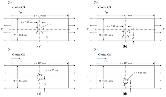
Figure 1.
Geometry, position, and loading condition related to the longitudinal axis for (a) a single symmetric square hole with rounded corners, (b) a single offset square hole with rounded corners, (c) a single symmetric circular hole, and (d) a single offset circular hole.
The various geometric parameters considered in this study are listed below.
- Plate width () = 38.1 mm.
- Hole dimension () = 6.35 mm.
- Hole edge-to-laminate edge distance () = 15.875, 7.938, 3.969, and 1.984 mm.
- () = 2.5, 1.25, 0.625, and 0.312.
- Corner radius () = 0.25, 0.5, 0.75, 1, 1.25, 1.5, 1.75, 2, 2.25, 2.5, 2.75, and 3 mm.
Figure 2 shows the corner radii considered in the finite element analysis in this study.
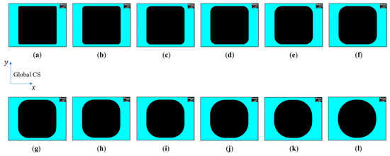
Figure 2.
Square hole corner radii considered in the finite element analysis: (a) = 0.25 mm, (b) = 0.5 mm, (c) = 0.75 mm, (d) = 1 mm, (e) = 1.25 mm, (f) = 1.5 mm, (g) = 1.75 mm, (h) = 2 mm, (i) = 2.25 mm, (j) = 2.5 mm, (k) = 2.75 mm, and (l) = 3 mm. The load is applied in the global -direction.
2.3. Stress Concentration Factors (SCFs)
Two different types of stress concentration factors are calculated, one for each lamina in the laminate, and the other for the laminate. To obtain the stress concentration factor for each lamina, the nominal stresses in the x–y directions and then in the 1–2 directions in each lamina, with no hole present, are first calculated using both finite element analysis and classical laminate analysis [21]. The nominal x–y stresses are designated as , , and , and the nominal 1–2 stresses are designated as , , and . Excellent agreement was obtained between the numerically calculated nominal stresses and the theoretical calculations based on laminate analysis.
In order to calculate the stress concentration factor for each individual lamina, the maximum lamina stresses , , and in each lamina with the hole are divided by the applied stress in that lamina with no hole. This approach is consistent with the method used by Barker [9] and Lal et al. [22] to determine the stress concentration factor of a unidirectional composite plate. In this study, = 0, 45, −45, and 90°. The lamina stress concentration factors in each lamina are defined in Equation (1).
At the laminate level, the stress concentration factor is obtained by dividing the maximum -direction stress in the laminate by the applied remote stress . The laminate SCF is given by Equation (2).
2.4. Finite Element Model
In this study, quadrilateral shell elements with eight nodes (SHELL281 in ANSYS) [23] and reduced integration were used to model the quasi-isotropic composite laminate. Each shell element (and therefore, each lamina) contained five through-thickness integration points: one at each of the top and bottom surfaces with the remaining points equidistant between the top and bottom surfaces. All stress field data were taken from the middle layer of the element; however, because the external loading is in-plane only, the stress results from the top, middle, and bottom layers of the elements were equal. When the middle layer is chosen for stress results, ANSYS averages the stresses from the top and bottom of the element [24]. A mapped meshing approach was used to ensure that the finite element model was computationally well-behaved, as well as time efficient. The plate was divided into several regions. This is shown in Figure 3 for a plate with a square hole with a 2 mm corner radius located at the center of the plate so that 15.875 mm. The total number of elements in the mapped mesh of this plate is 7680 and is comprised of the element sizes and numbers listed in Table 2. The area surrounding the hole is Region 3 in this figure and displays the finest mesh size, while larger element sizes are used in Regions 1 and 2. To ensure reliable results, the mesh in Region 3 was refined until convergence was achieved.
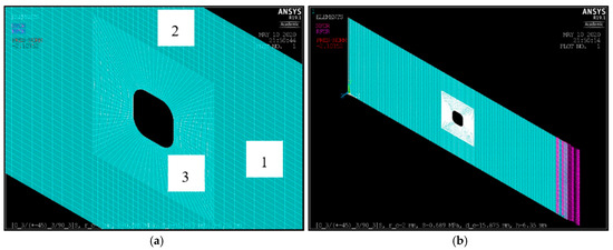
Figure 3.
(a) Element distribution in the three regions of the plate with a single centered square hole, with 2 mm and 15.875 mm; (b) remote tensile load applied at the left end (), with nodal and reaction forces on the constrained edge at the right end ().

Table 2.
Number and dimensions of elements per region in Figure 3a.
To ensure the integrity of the finite element model, simulation results for a single centered square hole with rounded corners in an isotopic plate and a quasi-isotropic laminate were compared to an existing closed form solution for an isotropic plate. Equations from Young et al. [25] for a stress concentration factor based on gross area for a rectangular hole with rounded corners in an infinitely wide thin plate subjected to in-plane uniaxial tension were used to calculate the theoretical . Equation (2) in Section 2.3 was used to calculate the for the finite isotropic plate and finite quasi-isotropic laminate. The square hole size was 6.35 mm, and three different corner radii were considered: 1, 2, and 3 mm. These three corner radii were selected only to validate the finite element model used in this study. The stress concentration factors listed in Table 3 show close agreements between the isotropic and quasi-isotropic values for all three corner radii.

Table 3.
Theoretical infinite width SCFs vs. FEA finite width SCFs for a single centered square hole with rounded corners in an isotropic plate and quasi-isotropic laminate.
3. Results
3.1. Maximum Stresses
3.1.1. Maximum
The behavior of the stress field for the single square hole depends on the corner radius , as well as the edge distance . The location of the greatest stress in the laminate for any given and occurs in the 0° laminas, specifically in the vicinity of the transition from the horizontal straight edge (parallel to the central axis of the laminate) of the hole to the curvature of the corner radius (Figure 4). This is consistent with the results from de Jong [11] in that the location of the highest stress is found in the neighborhood of the rounded corner. Similarly, Ref. [14] found that the location of the maximum stress for a rectangular hole in a [0] glass fiber-epoxy plate occurs in the vicinity of the rounded corner. Further, Savin [26] investigated curvilinear square holes in an isotropic plate subjected to uniaxial tension and found that the maximum stress occurs near the angles of the square and that as the radius of the rounding angles gets smaller, the stress concentrations near the hole increase substantially. Goyat et al. [27] studied the stress concentration in an infinite homogenous panel of titanium mono-boride containing a rounded rectangular hole reinforced with a functionally graded material layer of titanium and titanium mono-boride under uniaxial loading and found that the maximum stress occurs near the rounded corner. Finally, Brock [28] and Sobey [29] investigated square holes with rounded corners in an isotropic plate subjected to uniaxial tension and found that for a given hole, the maximum stress occurs near the beginning of the rounded corner. Such behavior can be seen in Figure 4 for the centered square hole with different values of corner radius in the quasi-isotropic laminate studied here.
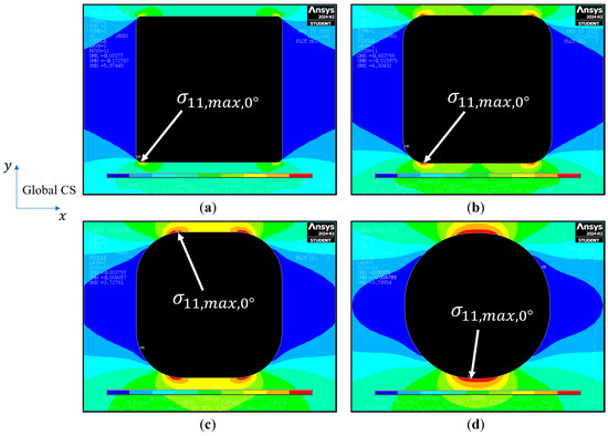
Figure 4.
Location of maximum stress in the 0° lamina with 15.875 mm (i.e., the hole is centrally located) for: (a) 0.25 mm, (b) 1 mm, (c) 2 mm, and (d) 3 mm. The load is applied in the global -direction.
For the case of the centered square hole, the magnitude of the stress in the 0° lamina is the same at each corner due to symmetry about the central axis. For the offset square holes, the maximum also occurs in the 0° lamina. This is because the fibers in the 0° lamina are parallel to the loading axis, and therefore carry most of the load applied to the laminate. For any given hole offset distance in the 0° lamina, the magnitude of the maximum reduces with increasing for 0.039 ≤ < 0.276 or 0.25 mm mm, but then increases for or mm. The maximum decreases as the edge distance increases or the hole offset decreases. This agrees with the results from Xiwu et al. [30], who found that the greater the eccentricity of a circular hole in a [04/±45]S finite laminated plate, the greater the stress concentration. Hong and Crews [31] found that the normalized maximum stress in a quasi-isotropic laminate with a centered circular hole increased as the width of the laminate decreased. A similar observation was made by Nguyen-Hoang and Becker [32] for a quasi-isotropic carbon fiber-epoxy laminate with a single centered circular hole. Additionally, Ref. [10] studied the stress distribution around a rectangular hole in a finite isotropic plate and found that the stress concentration factor increased as the plate’s aspect ratio decreased from 1 to 0.25. The “edge effect” has less of an influence on the 90° lamina, as is lower than for any given . This is similar to results from Hong et al. [33], where pin-loaded 90° laminates with varying ratios of width to circular hole diameter were shown to be less sensitive to the “edge effect” than were the 0° laminates.
For the centered square hole, the maximum stresses at all four corners of the hole follow the symmetry condition, as shown in Figure 5. For example, for the 0° lamina, the maximum displays the same magnitude at corners A, B, C, and D. As the hole is shifted from the central axis toward the laminate edge, the symmetry relationships are lost due to the combined influence of secondary bending arising from the hole offset from the loading axis and “edge effect”. For the offset holes, the maximum in the 0° lamina is also found at corners C and D, located closer to the laminate edge. The stress is lower at corners and , which are on the opposite side of the square hole, closer to the central axis of the laminate. Additionally, and . The difference in maximum stresses at C and D vs. A and B are plotted as a function of the hole edge-to-laminate edge distance normalized against the hole dimension in Figure 6.
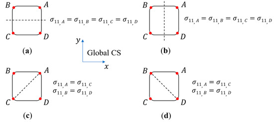
Figure 5.
Stress symmetry conditions based on fiber orientation directions for a single centered square hole: (a) 0° fiber, (b) 90° fiber, (c) 45° fiber, and (d) −45° fiber. The dashed lines indicate the direction of fiber orientation. Note that the side CD of the hole is closer to the laminate edge.
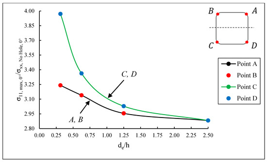
Figure 6.
Normalized stress in the 0° lamina at corners A through D for 2 mm. Note that side CD of the hole is closer to the laminate edge, and side AB is closer to the loading axis.
As with square holes, the maximum in the laminate containing a circular hole also decreases as the hole edge-to-laminate edge distance de increases or the hole offset decreases. The maximum on the periphery of the circular hole occurs in the 0° lamina at locations where the 0° fibers are tangent to the hole. However, the locations of the maximum in the ±45° laminas are not at the tangent points with the 45° or −45° fibers; instead, they are closer to points where the 0° fibers are tangent to the hole. The change in position of the maximum agrees with results from Ko [34], which determined that the locations of the maximum tangential stress points of a circular hole in an anisotropic composite plate shift with the change in fiber direction in relation to the loading axis.
3.1.2. Maximum
For the square hole with rounded corners, the maximum occurs in the 90° lamina, and the lowest stress is always found in the 0° lamina. Also, for any given hole offset distance in the 90° lamina, the magnitude of reduces with increasing for 0.039 ≤ < 0.276 or 0.25 mm mm, but then increases for or mm. The maximum decreases as the edge distance increases or the hole offset decreases.
3.1.3. Maximum
For the square hole with rounded corners, the greatest maximum always occurs in the 45° and −45° lamina; however, they are in opposite directions. The positive is in the −45° lamina, whereas the negative of is in the 45° lamina.
3.2. Lamina Stress Concentration Factors
The maximum SCFs for the various for each lamina as a function of the normalized corner radius, , are shown in Figure 7, Figure 8 and Figure 9. It can be seen that the maximum SCF values increase with decreasing , i.e., as the hole edge becomes closer to the laminate edge. Furthermore, as increases, i.e., the square hole corners become more rounded, the SCF curves approach the behavior of a circular hole. In general, there is a decreasing–increasing behavior in the SCF in the 0° lamina as the corner radius is increased for any given . This is consistent with the results from Ref. [14], where a [0] glass fiber-epoxy plate with a centrally located rectangular hole was found to produce a decreasing–increasing stress concentration behavior as the corner radius was increased. Figure 7 indicates that although the majority of the applied load is transferred through the 0° lamina, the highest SCF is found in the ±45° lamina. This is similar to the results from Sharma [35], which determined that for a circular hole in infinite graphite-epoxy and glass-epoxy laminated composite plates subjected to arbitrary biaxial loading at infinity, the stress concentration factor was greatly affected by fiber orientation. Further, Kaltakci [36] studied stress concentrations in a composite plate with a circular hole subjected to tension and found that the stress at failure of the composite plate is affected significantly by the fiber orientation angle.
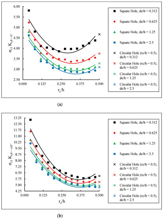
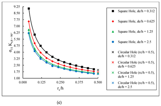
Figure 7.
SCFs in (a) 0° lamina, (b) ±45° lamina, and (c) 90° lamina.
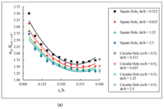
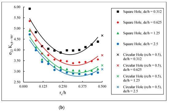
Figure 8.
SCFs in (a) ±45° lamina and (b) 90° lamina.
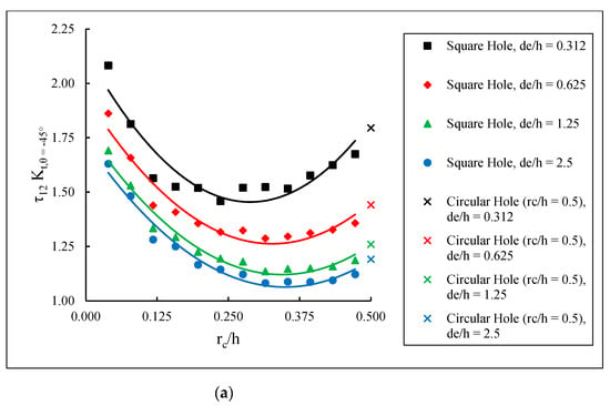
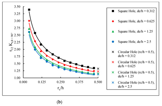
Figure 9.
SCFs in (a) −45° lamina and (b) 90° lamina.
For the square holes with rounded corners, the worst-case scenario is for = 0.25 mm. The maximum lamina SCF for the various cases of and = 0.25 mm are listed in Table 4. The maximum SCF occurs in the ±45° lamina, the maximum SCF occurs in the 90° lamina, and the maximum SCF occurs in the 90° lamina.

Table 4.
Effect of square hole edge-to-laminate edge distance on the maximum lamina stress concentration factor for = 0.25 mm.
The stress distributions for the most critical cases for the square hole with rounded corners are shown in Figure 10.
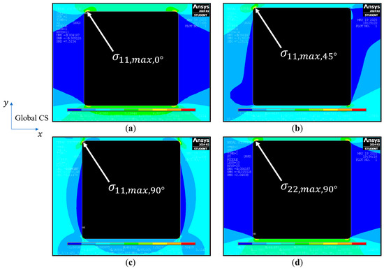
Figure 10.
Stress distributions for the most critical cases of 2.5 where 0.25 mm for: (a) in the 0° lamina, (b) in the 45° lamina, (c) in the 90° lamina, and (d) in the 90° lamina. The load is applied in the global -direction.
3.3. Laminate Stress Concentration Factors
The SCFs for the laminate with the square hole and various corner radii, along with the laminate containing the circular hole, were calculated using Equation (2) and are plotted in Figure 11. The laminate SCFs are based on the maximum at the hole edge, which for offset holes, occurs on the edge closer to the laminate edge. The combined effects of hole offset and “edge effect” can be observed in Figure 11. The laminate SCF is the highest at the lowest hole edge-to-laminate edge distance and is the lowest when the hole is at the center of the laminate, with the hole axis coinciding with the loading axis. It can be noted in Figure 11 that for each , the SCF of the laminate decreases with increasing corner radius until a minimum value is reached, after which it increases for increasing corner radius and approaches the corresponding SCF for a circular hole. This is consistent with the results from Heller et al. [37], where a similar behavior was found in a uniformly loaded finite width isotropic plate containing a centered square hole with rounded corners. The minimum SCF and the corner radius at which it occurs depends on . At all values investigated, a significant increase in SCF occurs for a between 0.312 and 0.625, i.e., for an edge distance between 0.312 and 0.625 of the square hole side. Furthermore, Figure 11 indicates that for any given , square holes can produce stress concentrations that are lower than those for circular holes. The minimum corner radius needed for this to occur depends on the hole edge-to-laminate edge distance. As Table 5 shows, they are 1.343, 1.294, 1.117, and 0.688 mm for equal to 15.875, 7.938, 3.969, and 1.984 mm, respectively. The corresponding offset distance from the center of the laminate to the center of the square hole is 0, 7.937, 11.906, and 13.891 mm. Walsh and Ochoa [38] observed in their study that a square hole has a lower stress concentration factor than a circular hole but did not consider the effect of its corner radius. The current study shows that this observation is valid only if the corner radius is higher than the minimum value, which depends on the offset distance or the closeness of the square hole to the edge of the laminate.
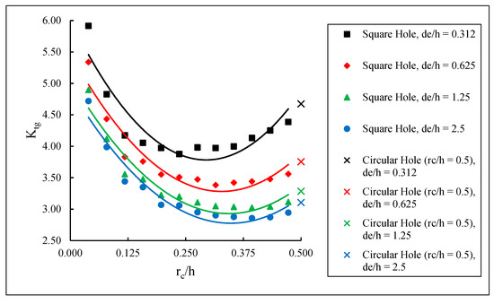
Figure 11.
Laminate SCFs for a 6.35 mm side square hole with rounded corners and for a 6.35 mm diameter circular hole.

Table 5.
Minimum corner radius of 6.35 mm side square holes with the same laminate stress concentration factor as that for the 6.35 mm diameter circular holes.
Figure 11 also shows that the corner radius of the square hole that produces the minimum SCF depends on . To consider the effect of corner radius on the minimum SCF more closely, the SCF of the laminate with the centered square hole is plotted in Figure 12. It shows that the minimum SCF for the laminate with a centered square hole occurs with a corner radius equal to 2.208 mm, which is approximately one-third of its width. This is consistent with the observations from Pilkey and Pilkey [1], in that an isotropic plate containing a square hole with corner radius equal to about one-third its width has a lower SCF than that of a circular hole of equivalent diameter. Further, Ref. [28] found that for an infinite isotropic plate subjected to uniaxial stress, the minimum stress occurs when the ratio of the corner radius to the width of the hole is equal to 0.375. In this study, that ratio becomes 0.35. For a single centered circular hole in a finite width isotropic plate, the Heywood formula from Ref. [1] yields 3.094. This value is within a 0.355% error of the SCF for the finite width laminate containing a single centered circular hole obtained from Equation (2), i.e., 3.105.
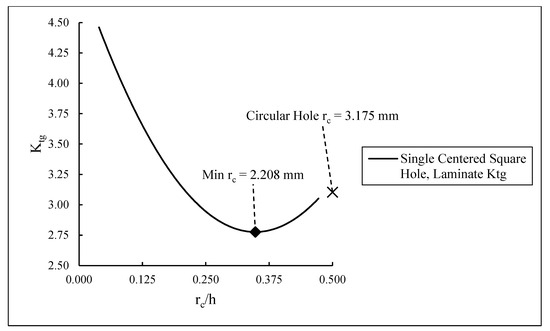
Figure 12.
Effect of corner radius on laminate SCFs for the quasi-isotropic laminate containing a centered square hole ( 15.875 mm).
Table 6 lists the corner radius needed to achieve the minimum SCF for the centered and offset square holes. The minimum SCF that can be achieved with square holes increases with decreasing , i.e., with higher offset. For the centered square hole, the minimum SCF is 2.776, and for the square hole closest to the edge, the minimum SCF is 3.783, which is 36.3% higher. This agrees with results from Brock [39], which showed that the minimum SCF for a square hole with rounded corners in an infinite isotropic plate subjected to uniaxial tension is 2.8. For the centered square hole, a corner radius of 2.208 mm produces the minimum SCF, while for the square hole closest to the edge, a higher minimum SCF occurs at a corner radius of 1.871 mm.

Table 6.
Effect of hole center offset on the minimum laminate stress concentration factor and the corresponding corner radius of 6.35 mm side square holes.
4. Conclusions
Stress distributions, maximum stress locations, and stress concentrations due to a single offset square hole with rounded corners in a finite width quasi-isotropic [03/(±45)3/903]S laminate subjected to an in-plane uniaxial tensile stress are explored here. For comparison, a single circular hole, with its diameter equivalent to the sides of the square hole, is also considered. In order to investigate the effect of hole offset, four different hole edge-to-laminate edge distances are considered. For the centered square hole, the maximum fiber-direction () stresses occur at the transition from the hole edges parallel to the loading direction to the rounded corners. For the circular holes, they occur at the hole edges parallel to the loading direction. In all cases, the maximum stress in the laminate is found in the 0° lamina, but the largest lamina stress concentration factor is found in the ±45° laminas. For the offset holes, the secondary bending effect due to load eccentricity, in addition to the direct stress, increases the magnitude of the maximum stresses for both the square hole and the circular hole. The presence of the laminate edge close to the hole edge gives rise to a marked increase in the maximum stress values, most notably in the 0° lamina.
The results of this study show that in general, both lamina and laminate stress concentration factors for the offset holes are higher at the hole edge that is closer to the laminate edge, and they increase with decreasing hole edge-to-laminate edge distance, i.e., with increasing offset. The laminate stress concentration factor for the square holes decreases with increasing corner radius, and after reaching a minimum value, it starts to increase. The minimum stress concentration factor increases with increasing offset. Depending on the hole dimensions and the edge distance, the stress concentration factor for square holes can be lower than that of circular holes.
The stress concentration information generated in this study will be useful in the design of quasi-isotropic composite laminates with square holes. A square hole has a lower stress concentration factor than a circular hole, provided that its corner radius is higher than a minimum value, which depends on the hole offset, i.e., the closeness of the square hole edge to the laminate edge. The stress concentration factor due to the presence of a square hole increases with increasing hole offset, and using a corner radius higher than the minimum value, it is possible to attain a stress concentration factor lower than that for a circular hole of the same size as the square hole. To avoid high stress concentration, the edge distance of the offset square hole should not be lower than one-quarter the square hole side, and the corner radius should be at least one-third the square hole side.
It should be noted that in addition to the in-plane stresses, there are also interlaminar stresses in laminates that are generally high at the hole edges and can initiate failure. In this research, only the stress concentrations due to in-plane stresses are considered. They can be applied to determine the notched tensile strength of the laminate using failure models, such as the point stress criterion or the average stress criterion [40,41], and also to design the hole dimensions and locations that will provide the maximum notched tensile strength. Our future research direction related to this topic is to consider the effect of multiple square holes with asymmetric and axisymmetric configurations.
Author Contributions
Conceptualization, P.K.M. and M.K.P.; methodology, P.K.M. and M.K.P.; software, M.K.P.; validation, M.K.P.; formal analysis, M.K.P.; investigation, M.K.P.; resources, P.K.M.; data curation, M.K.P.; writing—original draft, M.K.P.; writing—review and editing, P.K.M.; visualization, M.K.P.; supervision, P.K.M. All authors have read and agreed to the published version of the manuscript.
Funding
The authors received no funding for the research and authorship of this article.
Data Availability Statement
The original contributions presented in this study are included in the article. Further inquiries can be directed to the corresponding author.
Acknowledgments
The authors acknowledge the University of Michigan–Dearborn for providing the computing resources used in conducting the research reported in this article.
Conflicts of Interest
The authors declare that they have no known competing financial interests or personal relationships that could have appeared to influence the work reported in this paper.
Abbreviations
The following abbreviations are used in this manuscript:
| FEM | finite element models |
| FEA | finite element analysis |
| SCFs | stress concentration factors |
| SCF | stress concentration factor |
Nomenclature
The following nomenclature is used in this manuscript:
| laminate stress concentration factor | |
| lamina stress concentration factor, where = 0, 45, −45, and 90° | |
| normal stress in the fiber direction | |
| normal stress transverse to the fiber direction | |
| shear stress in the 1–2 plane |
References
- Pilkey, W.D.; Pilkey, D.F. Peterson’s Stress Concentration Factors, 3rd ed.; John Wiley & Sons, Inc.: Hoboken, NJ, USA, 2008. [Google Scholar]
- Tan, S.C. Stress Concentrations in Laminated Composites, 1st ed.; CRC Press: Boca Raton, FL, USA, 1994. [Google Scholar]
- Muskhelishvili, N.I. Some Basic Problems of Mathematical Theory of Elasticity, 2nd English, ed.; P. Noordhoff Ltd.: Groningen, The Netherlands, 1962. [Google Scholar]
- Kheradiya, M. Effects of Edge Distance, Hole Size Ratio and Hole Spacing on Peak Stresses of Composite Laminate with Multiple Holes. Master’s Thesis, The University of Texas at Arlington, Arlington, TX, USA, 2008. [Google Scholar]
- Ogonowski, J. Analytical study of finite geometry plates with stress concentrations. In Proceedings of the 21st Structures, Structural Dynamics, and Materials Conference, Seattle, WA, USA, 12–14 May 1980; pp. 694–698. [Google Scholar]
- Lekhnitskii, S.G. Anisotropic Plates; Tsai, S.W.; Cheron, T., Translators; Gordon and Breach Science Publishers: New York, NY, USA, 1968. [Google Scholar]
- Savin, G.N. Stress Concentration Around Holes; Pergamon Press: New York, NY, USA, 1961. [Google Scholar]
- Rowlands, R.E.; Daniel, I.M.; Whiteside, J.B. Geometric and Loading Effects on Strength of Composite Plates with Cutouts. In Proceedings of the Third Conference on Composite Materials: Testing and Design, Williamsburg, VA, USA, 21–22 March 1973; pp. 361–375. [Google Scholar] [CrossRef]
- Barker, R.M.; Dana, J.R.; Pryor, C.W. Stress concentrations near holes in laminates. J. Eng. Mech. Div. 1974, 100, 477–488. [Google Scholar] [CrossRef]
- Pan, Z.; Cheng, Y.; Liu, J. Stress analysis of a finite plate with a rectangular hole subjected to uniaxial tension using modified stress functions. Int. J. Mech. Sci. 2013, 75, 265–277. [Google Scholar] [CrossRef]
- de Jong, T. Stresses around rectangular holes in orthotropic plates. J. Compos. Mater. 1981, 15, 311–328. [Google Scholar] [CrossRef]
- Cannon, C.P. Stress Concentrations Around a Square Cutout in a Composite Plate. Master’s Thesis, The University of Texas at Arlington, Arlington, TX, USA, 2012. [Google Scholar]
- Zamanian, H.; Salehi, M. Modification to Heywood’s equations to estimate the stress concentration factors for unidirectional glass epoxy laminates with circular and square holes. Int. Res. J. Adv. Eng. Sci. 2016, 1, 18–25. [Google Scholar]
- Chauhan, M.M.; Sharma, D.S. Stresses in finite anisotropic plate weakened by rectangular hole. Int. J. Mech. Sci. 2015, 101–102, 272–279. [Google Scholar] [CrossRef]
- Rao, D.K.N.; Babu, M.R.; Reddy, K.R.N.; Sunil, D. Stress around square and rectangular cutouts in symmetric laminates. Compos. Struct. 2010, 92, 2845–2859. [Google Scholar] [CrossRef]
- Chauhan, M.M.; Sharma, D.S. Stress concentration at the corners of polygonal hole in finite plate. Aerosp. Sci. Tech. 2016, 58, 197–206. [Google Scholar] [CrossRef]
- Barbero, E.J.; Shahbazi, M. Determination of Material Properties for ANSYS Progressive Damage Analysis of Laminated Composites. Compos. Struct. 2017, 176, 768–779. [Google Scholar] [CrossRef]
- Barbero, E.J. Finite Element Analysis of Composite Materials Using ANSYS®, 2nd ed.; CRC Press: Boca Raton, FL, USA, 2014. [Google Scholar]
- ASTM D5766/D5766M-23; Standard Test Method for OpenHole Tensile Strength of Polymer Matrix Composite Laminates. ASTM International: West Conshohocken, PA, USA, 2023; Volume 15.03.
- ASTM D8509/D8509M-23; Standard Guide for Test Method Selection and Test Specimen Design for Bolted Joint Related Properties. ASTM International: West Conshohocken, PA, USA, 2023; Volume 15.03.
- Mallick, P.K. Fiber Reinforced Composites: Materials, Manufacturing, and Design, 3rd ed.; CRC Press: Boca Raton, FL, USA, 2008. [Google Scholar]
- Lal, A.; Sutaria, B.M.; Kumar, R. Stress analysis of composite plate with cutout of various shape. IOP Conf. Ser. Mater. Sci. Eng. 2020, 814, 012011. [Google Scholar] [CrossRef]
- SHELL281, ANSYS Mechanical APDL Element Reference, Release 14.0; ANSYS, Inc.: Canonsburg, PA, USA, 2011.
- SHELL, ANSYS Mechanical APDL Command Reference, Release 13.0; ANSYS, Inc.: Canonsburg, PA, USA, 2010.
- Young, W.C.; Budynas, R.G.; Sadegh, A.M. Roark’s Formulas for Stress and Strain, 8th ed.; McGraw Hill: New York, NY, USA, 2012; p. 817. [Google Scholar]
- Savin, G.N. Stress Distribution Around Holes, NASA/TT F-607; National Aeronautics and Space Administration: Washington, DC, USA, 1970. [Google Scholar]
- Goyat, V.; Verma, S.; Garg, R.K. Reduction of stress concentration for a rounded rectangular hole by using a functionally graded material layer. Acta Mech. 2017, 228, 3695–3707. [Google Scholar] [CrossRef]
- Brock, J.S. Analytical Determination of the Stresses Around Square Holes with Rounded Corners, Structural Mechanics Laboratory Research and Development Report 1149; Navy Department, David Taylor Model Basin: Bethesda, MD, USA, 1957. [Google Scholar]
- Sobey, A.J. Stress-Concentration Factors for Rounded Rectangular Holes in Infinite Sheets; Aeronautical Research Council Reports & Memoranda No. 3407; Aeronautical Research Council: London, UK, 1963. [Google Scholar]
- Xu, X.; Sun, L.; Fan, X. Stress concentration of finite composite laminates with elliptical hole. Comput. Struct. 1995, 57, 29–34. [Google Scholar] [CrossRef]
- Hong, C.S.; Crews, J.H., Jr. Stress-Concentration Factors for Finite Orthotropic Laminates with a Circular Hole and Uniaxial Loading, NASA/TP-1469; National Aeronautics and Space Administration, Langley Research Center: Hampton, VA, USA, 1979. [Google Scholar]
- Nguyen-Hoang, M.; Becker, W. Open holes in composite laminates with finite dimensions: Structural assessment by analytical methods. Arch. Appl. Mech. 2022, 92, 1101–1125. [Google Scholar] [CrossRef]
- Hong, C.S.; Crews, J.H., Jr.; Raju, I.S. Stress-Concentration Factors for Finite Orthotropic Laminates with a Pin-Loaded Hole, NASA/TP-1862; National Aeronautics and Space Administration, Langley Research Center: Hampton, VA, USA, 1981. [Google Scholar]
- Ko, W.L. Stress Concentration Around a Small Circular Hole in the HiMAT Composite Plate, NASA/TM-86038; National Aeronautics and Space Administration, Ames Research Center: Edwards, CA, USA, 1985. [Google Scholar]
- Sharma, D.S. Stress Concentration around Circular/Elliptical/Triangular cutouts in Infinite Composite Plate. In Proceedings of the World Congress on Engineering (WCE 2011), London, UK, 6–8 July 2011; Volume III. [Google Scholar]
- Kaltakci, M.Y. Stress concentrations and failure criteria in anisotropic plates with circular holes subjected to tension or compression. Comput. Struct. 1996, 61, 67–78. [Google Scholar] [CrossRef]
- Heller, S.R., Jr.; Brock, J.S.; Bart, R. The Stresses Around a Rectangular Opening with Rounded Corners in a Uniformly Loaded Plate, Structural Mechanics Laboratory Research and Development Report 1290; Navy Department, David Taylor Model Basin: Bethesda, MD, USA, 1959. [Google Scholar]
- Walsh, T.J.; Ochoa, O.O. Composites with multiple cutouts. Compos. Struct. 1993, 24, 117–124. [Google Scholar] [CrossRef]
- Brock, J.S. The Stresses Around Square Holes with Rounded Corners. J. Ship Res. 1958, 2, 37–41. [Google Scholar] [CrossRef]
- Whitney, J.M.; Nuismer, R.J. Stress fracture criteria for laminated composites containing stress concentrations. J. Compos. Mater. 1974, 8, 253–265. [Google Scholar] [CrossRef]
- Nuismer, R.J.; Whitney, J.M. Uniaxial Failure of Composite Laminates Containing Stress Concentrations, Fracture Mechanics of Composites; ASTM STP 593; ASTM: West Conshohocken, PA, USA, 1975; pp. 117–142. [Google Scholar] [CrossRef]
Disclaimer/Publisher’s Note: The statements, opinions and data contained in all publications are solely those of the individual author(s) and contributor(s) and not of MDPI and/or the editor(s). MDPI and/or the editor(s) disclaim responsibility for any injury to people or property resulting from any ideas, methods, instructions or products referred to in the content. |
© 2025 by the authors. Licensee MDPI, Basel, Switzerland. This article is an open access article distributed under the terms and conditions of the Creative Commons Attribution (CC BY) license (https://creativecommons.org/licenses/by/4.0/).