Article

Effects of Nanofiber Interleaving on the Strength and Failure Behavior of Co-Cured Composite Joints with Fiber Orientation Mismatch

1
Mechanical Engineering Department, California State University, Northridge, CA 91330, USA
2
Insight Technology Development, Kozyatagi, 34744 Istanbul, Turkey
*
Authors to whom correspondence should be addressed.
J. Compos. Sci. 2025, 9(6), 285; https://doi.org/10.3390/jcs9060285
Submission received: 28 March 2025 / Revised: 24 May 2025 / Accepted: 28 May 2025 / Published: 2 June 2025
(This article belongs to the Special Issue Feature Papers in Journal of Composites Science in 2025)

Abstract

This study investigates the effect of nanofiber interleaving on the mechanical performance of co-cured composite lap joints with effective fiber orientation mismatch at the joint interface. Joint configurations were defined by dominant yarn orientations at the bond line—denoted as (lower-substrate|upper-substrate)—and tested in (0|0), (90|90), and mismatched (0|90) setups using an 8-harness satin (8HS) fabric architecture, with and without nanofiber interlayers. Mechanical testing revealed an over ~25% reduction in lap shear strength for the (0|90) configuration relative to the matched (0|0) and (90|90) joints. Nanofiber interleaving effectively restored this loss, achieving strength levels comparable to the matched cases. Statistical analysis using two-way ANOVA and ANOM confirmed that both fiber orientation and nanofiber interleaving significantly influence joint strength, with a notable interaction effect (p < 0.001). Fractographic analysis further showed that nanofibers enhanced delamination resistance by stabilizing crack paths and suppressing crack jumps at crimping sites, especially in (0|90) joints where 0/90 yarn intersections are prone to early failure. These findings underscore the role of nanofiber interleaving in mitigating mismatch-induced failure mechanisms and improving the structural integrity of composite bonded interfaces.

1. Introduction

Advanced composite materials are indispensable for demanding applications in various sectors, including aerospace, automotive, and energy. Despite well-established practices and continuously advancing technology, the complex mechanical and thermal behavior of advanced composites, combined with a broad spectrum of design possibilities, continues to present challenges in achieving their full potential. One area that offers significant benefits, yet brings its own challenges, is the joining of composite materials both for high-performing structural assemblies and in-service repairs. Two types of joining techniques are typically used to assemble thermoset matrix composites: mechanical fastening and adhesive bonding. Adhesive bonding is arguably preferable, provided that strong bonding interfaces are created. It eliminates the need for drilling and the weight penalty associated with the mechanical fastening components [1,2,3]. In the case of bonded repairs, procedures should efficiently replace the damaged area while recovering structural integrity and performance [4].
Developing robust, reliable, and repeatable bonding techniques is essential for advanced composite applications. One of the main approaches for achieving effective bonded joints is co-curing, which combines the curing and joining processes into a single curing cycle. This method often utilizes a supported film adhesive requiring a compatible, if not the same, curing temperature as the composite substrates. However, a mismatch between the ideal curing pressure for the composite and the optimal pressure for the adhesive can result in adhesive overflow, leading to manufacturing defects within the composite substrates [1]. To address this potential issue in structural joints, such as those in stiffened panels, co-curing can be performed using the resin of the composite material itself, eliminating the need for additional adhesives [5].
The present study explores the co-cured lap joints of substrates without the use of adhesives but with the integration of a joint interfacial nonwoven veil made of polymeric nanofibers. The use of nonwoven polymeric veils has been of great interest for enhancing the mechanical behavior of laminated composites by various manufacturing techniques. Self-supporting thin thermoplastic nonwoven veils placed between fiber-reinforced epoxy matrix prepreg plies have been extensively studied and proven effective without causing significant weight penalties [6,7,8]. For example, Quan et al. [6] demonstrated that 15 g/m2 (GSM) PA-based microfiber veils improved the mode I fatigue resistance energy of unidirectional carbon–epoxy composites by 143%, attributed to enhanced crack deflection and bridging mechanisms. Wang et al. [9] investigated the failure behavior of composite joints. They reported that it was affected by two-scale toughening using CSR (core–shell rubber) nanoparticles and microfiber veils compared to untoughened and single-scale toughened joints.
As an alternative to microfiber interleaving veils in composites, lighter and thinner veils made from electrospun polymeric nanofibers have been explored. The concept of using electrospun polymer nanofibers to enhance the interfacial strength and toughness of polymer matrix composites (PMCs) was first introduced by Dzenis and Reneker in a 2001 patent [10]. Building on this idea, Wu [11,12] conducted extensive Ph.D. research in the early 2000s, systematically investigating the toughening effects of electrospun nanofibers embedded at the interfaces of carbon–fiber-reinforced PMCs under quasi-static, dynamic, impact, and fatigue loading conditions, along with associated toughening mechanisms. Further studies by Qi et al. [13,14,15,16] focused on carbonized polymer nanofibers and electrospun glass nanofibers, assessing their impact on interfacial toughness when incorporated into fiber-reinforced PMCs. Wu et al. [17] and Sinha-Ray et al. [18] also examined the potential for both interfacial toughening and self-healing, utilizing core–shell nanofibers loaded with healing agents and embedded at composite interfaces. The early developments of electrospun nanofiber applications for toughening and self-healing in PMCs, particularly before 2014, were comprehensively reviewed in [19,20]. Additional studies [21,22,23,24,25,26,27,28,29] conducted across different periods have further demonstrated the potential of electrospun nanofibers to enhance the toughness of resin-dominated interlaminar bonding regions between adjacent reinforcing plies in structural composites. These nanofibrous veils are typically porous, with fiber diameters ranging from 100 to 500 nm [27]. In some cases, they are designed as multiscale, highly hybridized structures that can also incorporate spatially well-distributed larger particles, such as milled carbon fibers [28]. During the curing cycle of the host composite, epoxy resin infiltrates these veils, resulting in the in situ formation of thin, nanofiber-reinforced epoxy nanocomposite interlayers [30,31]. Within these interlayers, the nanofibers generally retain their nonwoven morphology and high surface area, thereby increasing the energy required to initiate and propagate microcracks and delamination between adjacent structural plies [22,23,24,25,26,27,28,29,32,33].
Esenoglu et al. [34] demonstrated that coating their in-house produced PA66 nanofibers onto the joining region significantly enhanced the mechanical behavior of the composite joints, including improvements in single-lap shear strength, Charpy impact energy, and mode I fracture toughness. Minosi et al. [35] investigated the effect of commercially available XantuLayr electrospun XD 10 polyamide nanofibers on the mode I fracture toughness of epoxy adhesive joints. Their results showed that nanofibers applied at the substrate/adhesive interface improved fracture toughness by 32%, but no improvement was observed when nanofibers were placed in the middle of the adhesive layer.
In line with the importance of the joint interfaces, an impactful factor to consider is the fiber orientation mismatch between the joining surfaces. This challenge can be effectively addressed through deliberate design decisions and the appropriate selection of fiber-reinforcement architectures. For instance, neighbor unidirectional plies are effective in aligning/controlling fiber orientations with respect to each other. On the other hand, standard-tow plain-woven fabrics interlace fiber/yarns in perpendicular directions, creating a crisscross pattern. While this weave provides balanced strength in two directions, it introduces slight undulations or ‘crimps’ where the fibers interlace. These crimps are uniformly distributed throughout the fabric interfaces, leading to minor, localized mismatches in fiber alignment [35]. Despite these minor deviations, plain weave fabric plies at the interfaces maintain overall effective fiber orientation control with respect to each other. However, more complex reinforcement architectures, such as non-crimp fiber multidirectional/multi-layer reinforcement packs or single-layer weaves like 8-harness satin (8HS) [36] and spread-tow plain weave arguably require additional attention to ensure compatibility and optimal performance at the joint interfaces. In particular, achieving proper surface alignment or deliberately flipping layers during lay-up can be effective strategies to avoid fiber orientation mismatches. Figure 1 illustrates the rationale behind the 8HS weave pattern, starting with a comparison to plain weave in terms of the yarn exposure characteristics observed at the top and bottom surfaces of a single ply. Although it is a single layer, the dominant yarn orientations on the two surfaces of the 8HS fabric are orthogonal. When standard stacking procedures are followed, this characteristic can lead to joint interfaces with significant fiber orientation mismatches (i.e., 0° and 90°), potentially compromising joint integrity.
This study hypothesizes that the potential compromise in mechanical performance caused by fiber orientation mismatch at bonded joint interfaces can be effectively mitigated through the incorporation of nanofibrous interleaving layers. Specifically, we examine the performance of electrospun nanofiber veils interleaved within single-lap joints (SLJs) fabricated from 8-harness satin (8HS) fabric prepregs. The use of 8HS fabric enables alternating surface fiber orientations at the joint interface—even though the substrates possess identical in-plane stiffness—providing a unique opportunity to investigate the effects of yarn-level mismatch. This is achieved by simply flipping the plies during lay-up without altering the ply-level orientation. Furthermore, this material system allows us to explore how nanofiber interleaving performs in the presence of typical manufacturing and architectural imperfections such as voids, yarn undulations, and resin-rich pockets at the bond line. Three distinct interface configurations were studied, (0|0), (90|90), and (0|90), where the notation represents the dominant fiber/yarn orientation on the lower and upper substrate surfaces at the bond line, respectively (see Figure 1D for schematic yarn-level interaction scenarios). We present comparative analyses of failure loads for these SLJ specimens, including statistical assessments of the influence of joint interface configuration via dominant yarn orientation and the presence of nanofibrous interleaves. Detailed fracture surface characterizations support our discussion of the governing failure mechanisms and demonstrate the effectiveness of nanofiber interleaving in enhancing joint performance.

2. Experimental Section

This experiment-based research encompasses several branches of hands-on work involving interconnected efforts to ensure the high-quality preparation and testing of bonded lap joint samples. The primary tasks include the following:
  • Prepreg lay-up: Carefully layering prepreg composite materials.
  • Integration of nanofibers at the bond interface: Incorporating nanofibrous veils into the bond line to enhance mechanical performance and optimize the adhesion characteristics.
  • Cutting lap joint samples: Shaping the bonded samples to precise geometrical dimensions for accurate and reproducible mechanical testing.
  • Tensile testing of bonded lap joints: Evaluating the mechanical strength and failure modes of the samples using tensile testing techniques.
  • Scanning electron microscope (SEM) analysis: Conducting a detailed analysis of the bonded coupons post-testing to assess the bonding quality, fiber distribution, and failure mechanisms.

2.1. Material Selection

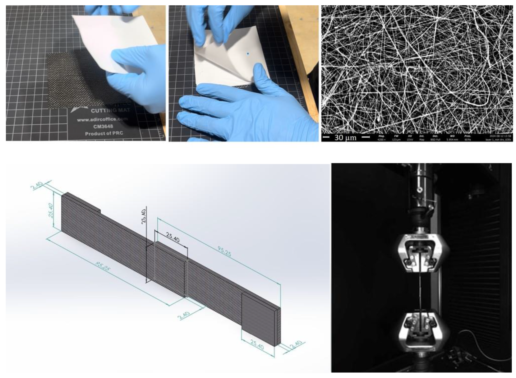
The goal is to investigate the effects of polymeric nanofibrous interleaving veils in co-cured bonded joints. In these joints, the bonding interface of the substrates may inherently present fiber orientation mismatches. To address this, the base composite material with 8HS fabric was selected. Specifically, Cycom 5320-1 prepregs T650-35 3K 8HS Fabric 36% RW by SYENSQO, USA. CYCOM 5320 (Anaheim, CA, USA) is a toughened epoxy designed for vacuum-bag-only or out-of-autoclave processing. Cytec Thornel® T-650/35 3K carbon fiber (SYENSQO, Anaheim, CA, USA), produced from a polyacrylonitrile (PAN) precursor for the 8HS weave pattern, has a filament diameter of 6.8 µm, a tensile strength of 4550 MPa, and a tensile modulus of 241 GPa. The prepreg contains 36% resin by weight, corresponding to a fiber volume fraction of approximately 57%. Secondly, as the other essential material component, tough thermoplastic electrospun nanofiber interleaving veils XantuLayr®, denoted herein as X, were purchased from NANOLAYR Ltd., Auckland, New Zealand. The XantuLayr® used in this study has an areal weight of 3 GSM (g/m2). It is a thermoplastic PA66 nanofiber veil made via electrospinning. The average nanofiber diameter is about 252 ± 40 nm. The total surface area of nanofibers in a planar area of 0.6 × 10⁻³ m2 (1″ × 1″) is about 29.7 × 10⁻³ m2. Figure 2 exemplifies the manual integration of the X on 8HS prepreg and shows an SEM image of XantuLayr®.

2.2. Lap Joint Design and Preparation

This study utilizes single-lap joint (SLJ) specimens to evaluate the bond interface structural property and to validate the nanofiber performance, which typically plays a crucial role in resisting the crack and delamination of laminates [21,22,23,24,25,26,27,28,29]. The dimensions of the single-lap joint specimens are shown in Figure 2. The bond region has dimensions of 25.4 × 25.4 mm2. Tabs of 25.4 × 25.4 mm2 were also co-cured at the top and bottom adherends’ gripping ends in order to eliminate the eccentricity of the bond line.

2.3. Manufacturing of Co-Cured SLJ Samples

Composite adherend stacks were made of Cycom 5320-1 carbon fiber 8HS prepreg plies. Table 1 summarizes the stacks of the bottom and top adherends, (BA) and (TA), respectively, in reference to Figure 1. A total of six different joint interfaces were created: three with and three without nanofiber veils, X. Note that the in-plane stiffness of the adherents is identical. The SLJ specimen panels were vacuum-bagged and cured for 2 h between the heated platens of a hot press (20 ton capacity with 7 × 7″ Heated Platens by DABPRESS, Shenzhen, China), without the application of additional mechanical pressure. All composite specimens were fabricated using 8-harness satin (8HS) prepreg under full vacuum-bagging conditions. A single-stage curing protocol was employed at 135 °C for 2 h and 30 min. Each batch consisted of five lap joint specimens, systematically labeled (a to e). During this manufacturing process, no foreign adhesives were used for bonding; the resin of the prepreg material formed the lap joints. The SLJ specimens were cut according to the desired dimensions using a diamond-coated circular saw with an automated cutting speed. Then, a visual inspection of the lap joint was carried out to check its dimensions and finishing.
The experimental campaign was effectively aligned with a categorical two-factor factorial design, incorporating two independent variables: orientation and nanofiber. These factors were defined for statistical screening through ANOVA using Minitab (version 22.2.2.), as summarized in Table 2. Orientation was treated as a three-level categorical factor corresponding to the joint interface configurations: (0|0), (90|90), and (0|90). Nanofiber was treated as a two-level categorical factor—Yes and No—indicating the presence or absence of nanofiber interleaving (X-interleaving), respectively. The six factorial configurations, each represented by five specimens, resulted in a total of thirty samples.

2.4. Mechanical Testing

As shown in Figure 2, SLJ specimens were tested in tension mode until failure at a 2 mm/min loading rate using a 100 kN AGX-V Universal Testing Machine (Shimadzu, Kyoto, Japan) with wedge grips. The tensile-tested samples were then segregated as upper and bottom adherends.

2.5. Electron Microscopy

Scanning electron microscopy (SEM) samples of 25.4 × 25.4 mm2 failure surfaces were cut by a diamond-coated saw. The failure surface coupons were cleaned and gold-coated before being fed into the Phenom XL G2 Desktop SEM (Thermo Fisher Scientific, Waltham, MA, USA).

3. Results and Discussion

3.1. Mechanical Test Data and Statistical Analysis

The tensile test results for the co-cured single-lap joint specimens are summarized in Table 3. Comparisons between joints with and without nanofiber interleaving reveal a significant enhancement in the maximum load-bearing capacity when nanofibers are incorporated at the bond interface.
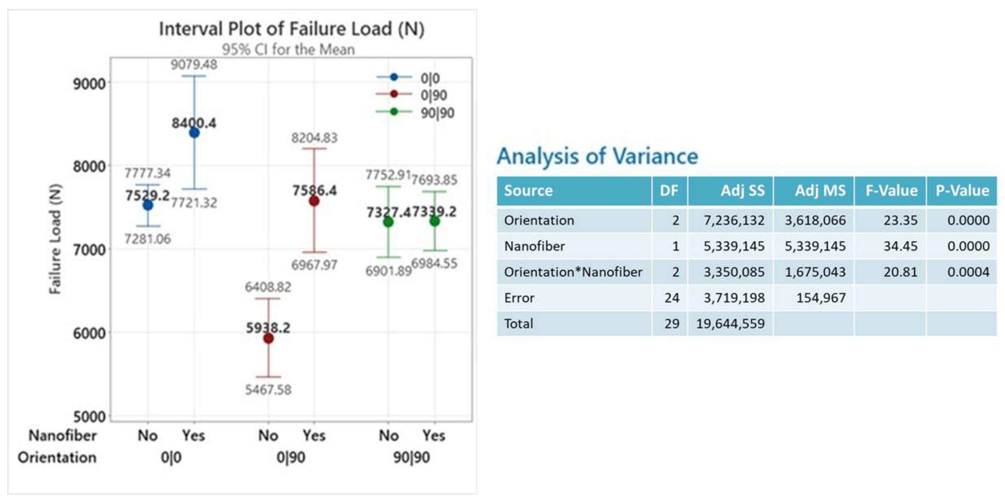
A statistical analysis of our data was performed using Minitab. Figure 3 (left) illustrates the interval plot of a single-lap joint (SLJ) failure load showing mean values and 95% confidence intervals for each configuration. Notable increases in mean failure loads are observed with nanofiber interleaving, especially for the (0|90) configuration. Figure 3 (right) also presents the ANOVA table, which clearly demonstrates the statistical significance (near-zero p-values) of both main factors—orientation and nanofiber interleaving—as well as their interaction (p-value < 0.001) in influencing the SLJ failure load.
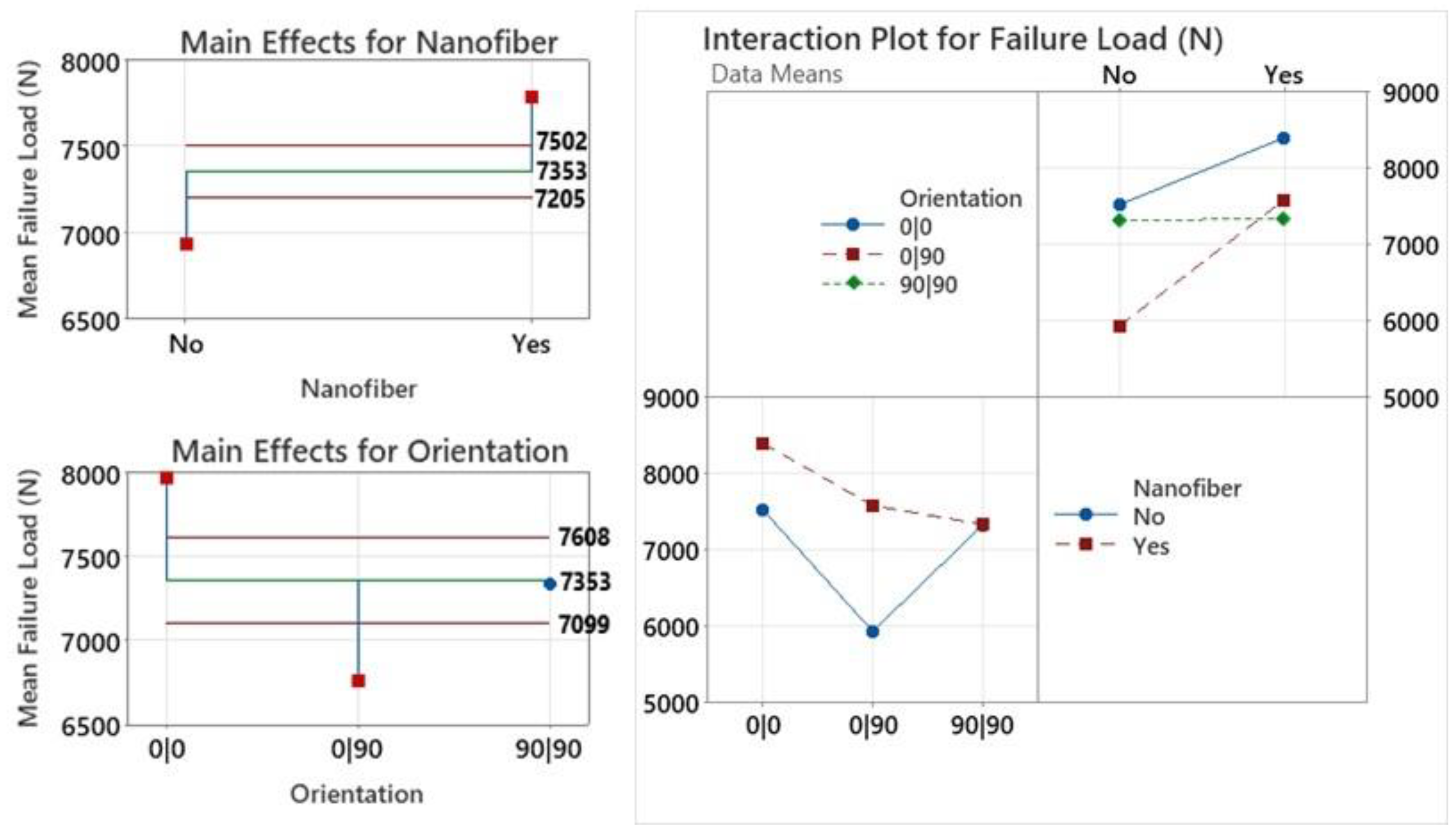
In the main effects plot for the nanofiber factor shown in Figure 4 (upper left), the mean failure loads for the absence and presence of nanofiber interleaving are 6932 N and 7775 N, respectively. Both values fall outside the decision band (7205 N to 7502 N) calculated at a significance level of α = 0.05 (indicated by red lines). This result confirms that the deviation of each group mean from the overall mean is statistically significant. Therefore, we have strong statistical evidence that the presence of nanofibers significantly increases the mean failure load of the joints, while their absence leads to a significantly lower mean. Similarly, in the main effects plot for orientation (Figure 4, lower left), the mean failure loads for the (0|0) (7965 N) and (0|90) (6762 N) configurations fall outside the decision limits (7099 N to 7608 N) at a significance level of α = 0.05 (indicated by the red lines). This indicates that the main effects for these two configurations are statistically significant. In contrast, the mean failure load for the (90|90) configuration (7333 N) lies within the decision limits band, suggesting that this orientation does not produce a statistically significant main effect. Moreover, Figure 4 (right) presents the interaction effects between the fiber orientation and the presence of nanofibers. While all configurations show strength improvement with nanofiber interleaving, the degree of enhancement varies—most notably in the (0|90) configuration. The interaction plot demonstrates a statistically significant interplay between the two factors. Nanofiber inclusion increases the failure load across all orientations; however, the (0|90) configuration, which initially exhibits the weakest performance, shows the most substantial improvement. With nanofibers, its strength approaches that of the stronger (0|0) and (90|90) configurations. This underscores the effectiveness of nanofiber reinforcement, particularly in mitigating weaknesses at mismatched joint interfaces.
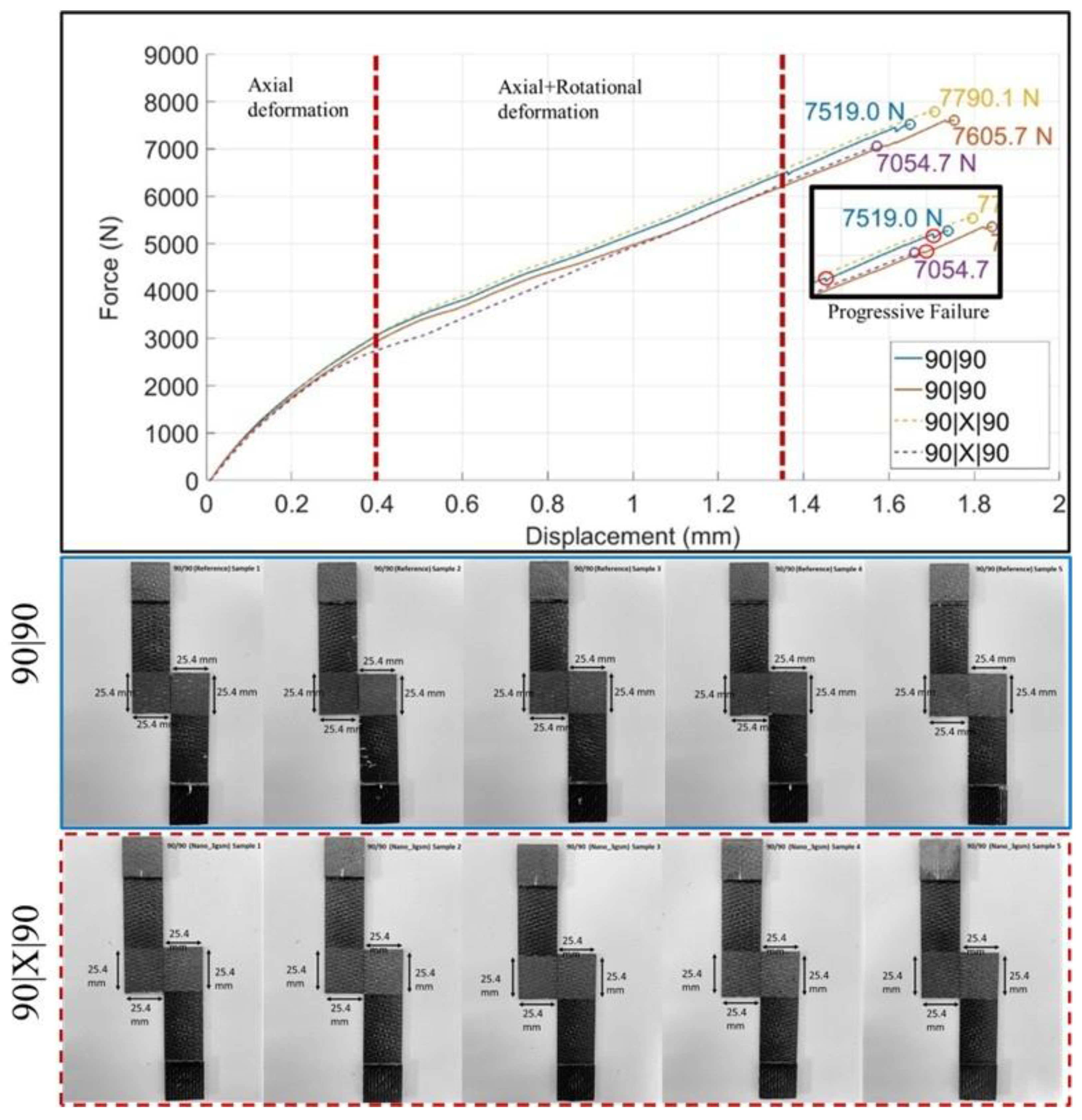
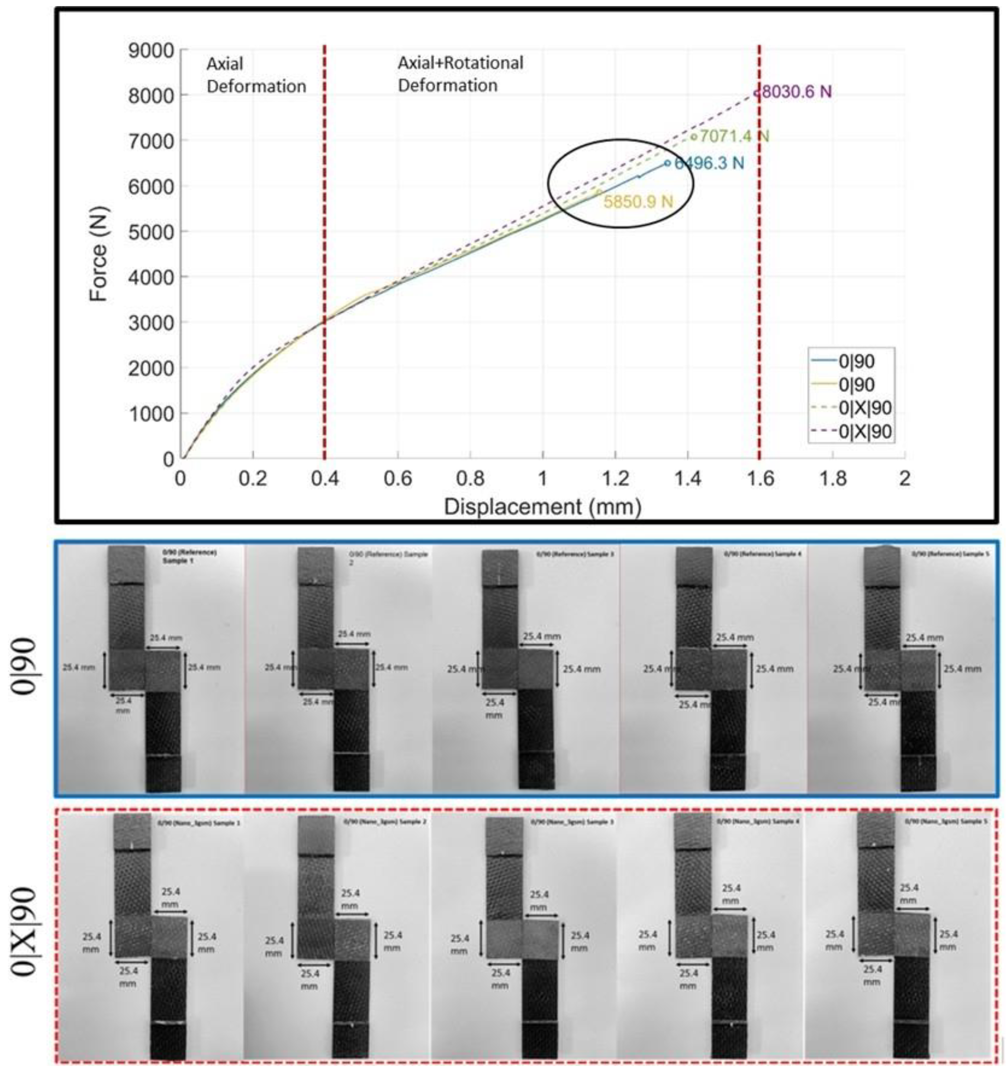
In single-lap joint tests, the force–displacement curves (Figure 5, Figure 7 and Figure 9) exhibit two distinct regions. The initial non-linear segment—referred to as the “axial deformation dominant region”—is characterized by axial stretching combined with bending, while the specimen remains relatively straight. This is followed by a region of nearly constant slope, marking a transition in the deformation behavior. Although this transition is gradual, a turning point or “knee” was nominally identified on the figures to aid in discussion. The region beyond the knee is termed the “axial and rotational deformation region,” distinguished by increased joint rotation due to the asymmetric geometry of the single-lap configuration. In metallic adherends, such a knee/transition typically signals the onset of plastic deformation. However, in composite adherends, as in the present study, it is attributed to a shift in the deformation mode at the joint—primarily due to rotation of the bonded plane relative to the loading axis. Importantly, no evidence of progressive failure was observed to suggest that it contributed to the change in slope in the composite specimens. Note that when the effective smeared stiffness of the woven plies remains unchanged regardless of ply flipping, the resulting [ABD] stiffness matrices for the three stacking configurations are expected to be nearly identical. However, this assumption does not fully hold for the 8HS architecture (except for the in-plane stiffness matrix [A]), as flipping the plies alternates the dominant fiber/yarn orientation at the surfaces, as illustrated in Figure 1. This characteristic introduces variations in surface-level stiffness and potentially alters joint deformation behavior, suggesting that joint rotations among the configurations may differ. For example, the joint regions formed by stacking the top and bottom adherends in the (0|0), (0|X|0), (90|90), and (90|X|90) configurations are symmetric with respect to their midplanes. In contrast, the mismatched configurations, (0|90) and (0|X|90), lack midplane symmetry, which can influence the rotational response and failure mechanisms at the bond line.
The subsequent sections provide a detailed fractographic analysis to examine how nanofiber interleaving affects these deformation interactions at the bond line and adjacent ply interfaces.

3.2. (0|0) and (0|X|0) Joint Interfaces
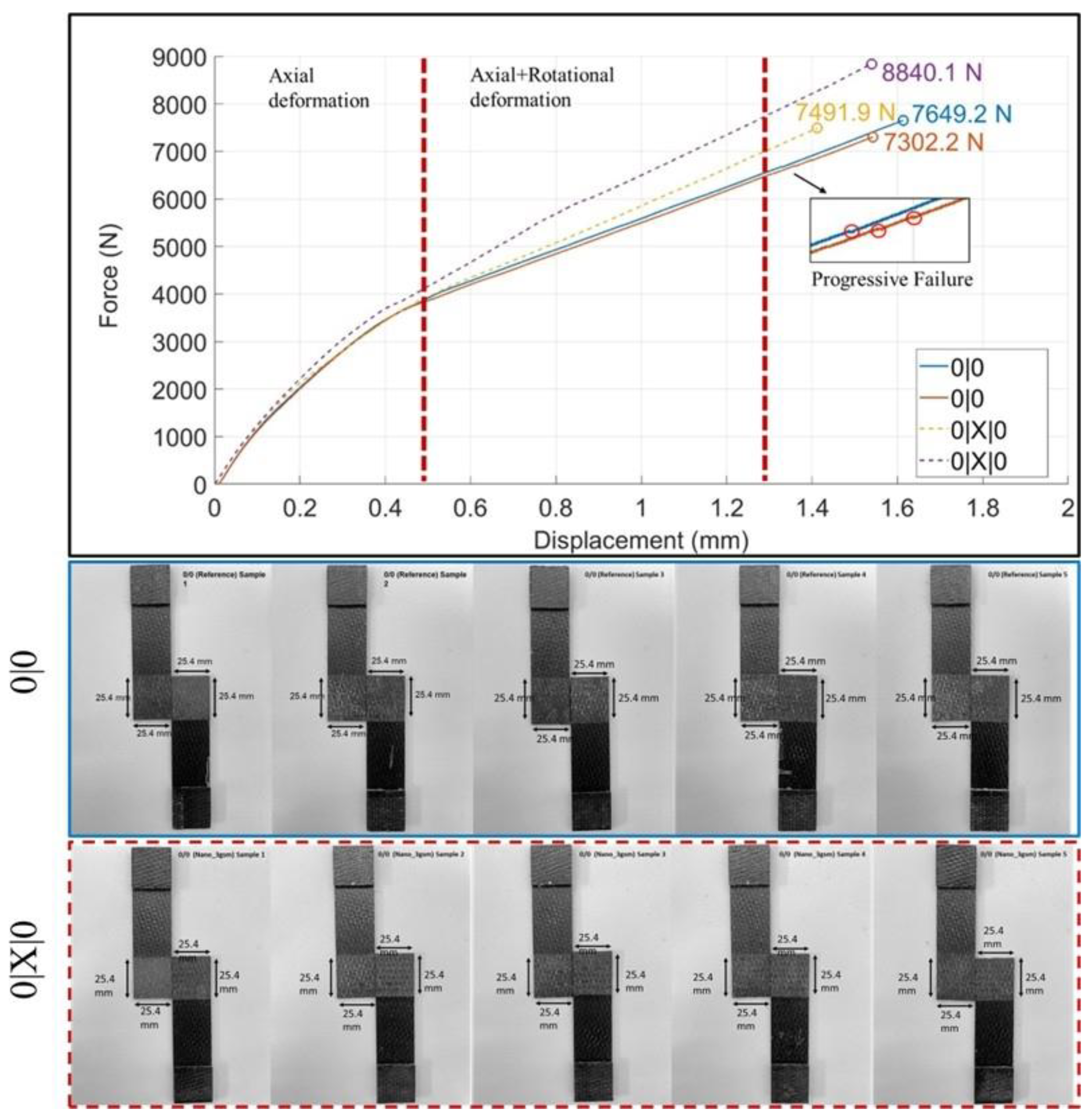
Test results indicate that the (0|X|0) configuration in Table 3 leads to an approximately 12% increase in the average failure load. However, as evident in Figure 6B, the standard deviation is higher, with the failure load averaging 8400 ± 547 N. The lowest failure load for the interleaved joint interface, 7492 N, was very close to the average failure load of the reference configuration. It reached as high as 8840 N, demonstrating significant enhancement but with potential variability.
When the (0|0) and (0|X|0) joint interface samples are compared with reference to the force–displacement curves, it can be concluded that they exhibit similar behavior in the initial deformation region prior to the nominal knee point. However, their responses after the knee point are significantly different, as the (0|X|0) joint interfaces demonstrated the ability to sustain higher loads during the rotational movement. On the curves of the (0|0) joint interface specimens, minor subsequent force drops (in the inset of Figure 5) are noticeable. These can be attributed to the progressive formation of critical damage in the joint interface, which occurs prior to final failure. They were suppressed in the (0|X|0) bonding interface configuration. These observations suggest that nanofibrous interlayers effectively mitigate micro-damage coalescence, typically leading to intermediate failure events [37]. Such local failure events are generally highly dependent on the topological features and bond quality at ply-to-ply interfaces [38]. They are further discussed in detail in Figure 6 to fully understand the failure modes influenced by the presence of interleaving nanofibers. Fractographic observations are presented with reference to the sampled portrayals of possible yarn-scale interactions specific to the 8HS weave (recall Figure 1).
Figure 5. Representative load vs. displacement curves for the (0|0) and (0|X|0) joint interface samples and views from the fractured specimens.
Jcs 09 00285 g005
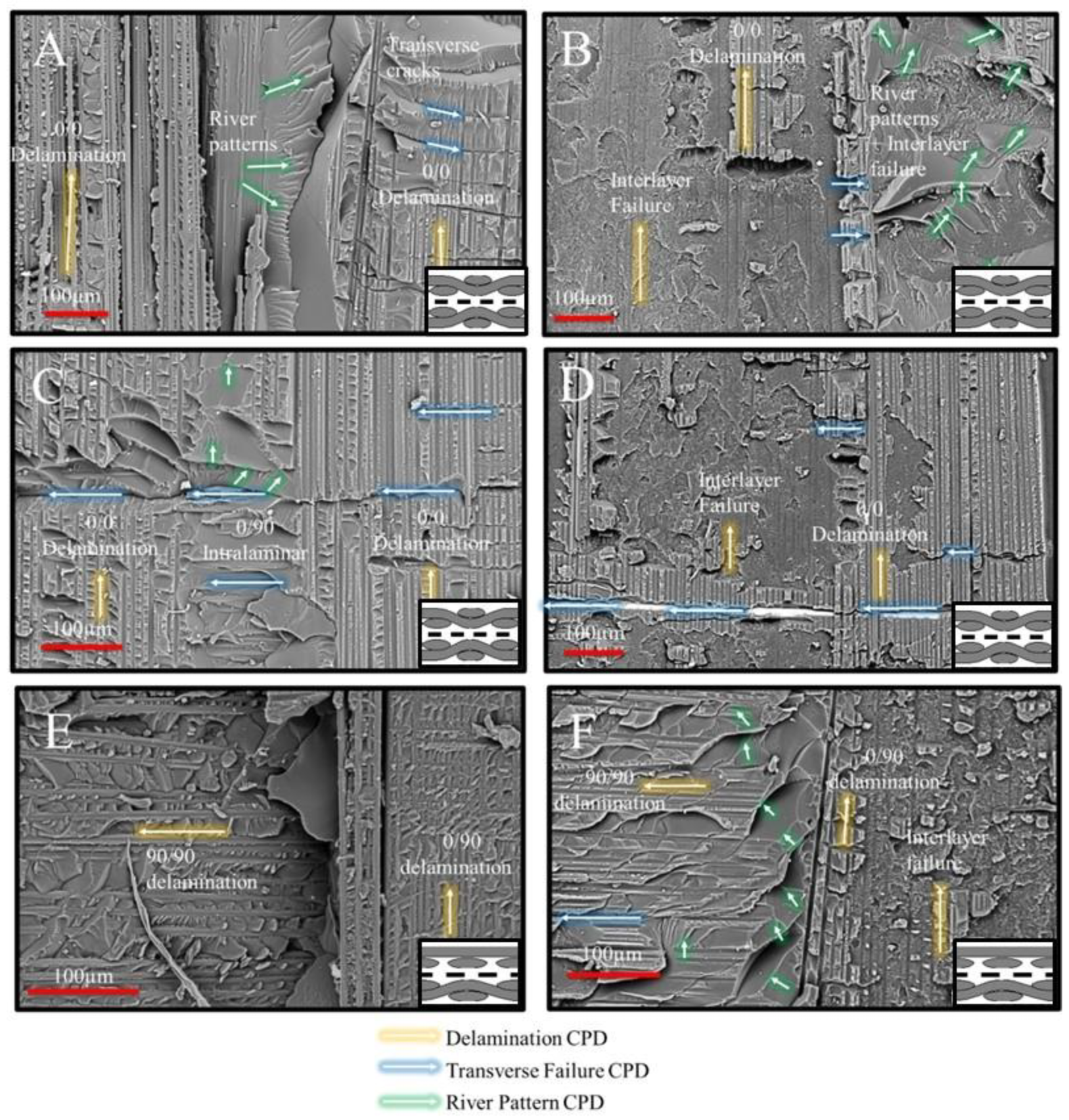
A representative region of interest on the fracture surface of the (0|0) joint interface sample is depicted in Figure 6A, highlighting a potential crack jump site caused by local yarn crimping. The intermittent occurrences of un-crimped warp yarn (0°) at the (0|0) joint interfaces are separated by an in situ-formed resin film. On the left-hand side, the failure mode is identified as 0/0 delamination (zone of stacked 0 yarns, i.e., 0° yarn interaction sites). The delamination mode in this region is mode II dominant, as evidenced by the presence of hackles in between the carbon fiber imprints [39]. The orientation of the river patterns (highlighted by green arrows) and the featureless appearance of the resin-rich zone suggest an unstable crack-front jump between the yarn interfaces [40]. The observed 0/0 delamination on the right suggests mode I dominance, intermittently interrupted by transverse failure events occurring at the interface of the 0° yarns of the adherends, above which the neighboring 90° yarn crimp influences the failure progression. It is also essential to highlight the rotational change in the fiber direction in this region, suggesting the occurrence of yarn rotation under lap shear loading at fiber crimping sites.
A similar region of interest near a crimping site in the (0|X|0) joint interface is shown in Figure 6B. A resin-rich region partially reinforced with the nanofibers is clearly distinguishable, once again highlighting the formation of river patterns. Unlike the (0|0) case in Figure 6A, the river patterns appear more scattered, and the surface is noticeably rougher than in the non-interleaved sample. This observation suggests that nanofibers enhance the resistance of (0|0) yarn interfaces in crimping regions against unstable crack propagation, which could otherwise significantly reduce the joint strength. Moreover, the failure regime of the nanofibrous interlayer on the 0/0 delamination surfaces exhibited shallow carbon fiber imprints, indicating a favorable interaction between the yarn and the nanocomposite interlayer. Additionally, the complete transition of the failure mode to interlayer failure suggests cohesive failure within the nanofiber/resin nanocomposite region, which is expected to exhibit higher strength compared to adhesion failure at the fiber/matrix interfaces [40].
Figure 6. Fracture surfaces: (A) resin-rich region on intermittent un-crimped warp yarn (0°) in the (0|0) joint interface case, (B) corresponding region in the nanocomposite interlayered (0|X|0) joint interface case, (C,D) interlayer failure-dominant regions in (0|0) and (0|X|0) joint interfaces, respectively, and (E,F) yarn intersection location in (0|0) and (0|X|0) joint interfaces, respectively (CPD: crack propagation direction).
Jcs 09 00285 g006
The top adherend’s flipped-over stack of plies increases the effective number and length of 0/0 yarn interaction sites at the joint interface with the bottom adherend stack. A region of interest on such an intermittent un-crimped 0° yarn interface in a (0|0) joint sample is shown in Figure 6C. The presence of long-transverse failure marks (highlighted by blue arrows) interfering with 0/0 delamination shows the degradation of 0° yarns triggered by the transverse failure of neighboring crimp-to-crimp 90/90 yarns. This mode is even more noticeable as an intralaminar failure progression from a 90° Jcs 09 00285 i007 yarn crimp toward a 0/0 delamination surface was captured in the image. Step-wise damage formation in the featureless resin phase exhibits parallel-aligned river patterns, providing direct evidence of intralaminar damage at 90° transitioning into interlaminar damage at the (0|0) interface. An investigation of the region of interest with similar damage progression in (0|X|0) (Figure 6D) suggests that the interlaminar propagation of a transverse crack at the 90° yarn crimp reveals the nanofiber-toughened nanocomposite region, rather than the weaker resin phase observed in Figure 6C. This observation provides strong evidence of the nanofibrous interlayers’ capability to toughen resin-rich interlaminar regions and enhance crack deflection.
The final region of interest in this case was at the crimp where the 90/0 yarn intersection Jcs 09 00285 i008 occurs within the 8HS ply (Figure 6E). The weft (90°) and warp (0°) yarns were distinctly separated, with a visible chunk of excess resin at their junction. Mode I-dominated 0/90 delamination was observed progressing in the 0° direction, while mode II-dominated delamination occurred on the 90° yarn. The failure at the excess resin chunk appeared smooth, lacking river pattern formations, suggesting a highly unstable crack initiation from the crimping region toward the 90° yarn. This is also evident from the decreasing size of the hackle patterns when traced from the yarn intersection site toward the 90° yarn. A similar region of interest at the yarn intersection for the (0|X|0) case is shown in Figure 6F. Unlike Figure 6E, there is no distinct separation between 0° and 90° yarns, and an excess resin phase is present, now exhibiting river patterns. The delamination pattern in the 0° yarn alternated between interlayer failure and mode II-dominated crack propagation [41] at the 0/90 interface. The reduction in the mode I component of the mixed-mode fracture may have mitigated critical separation in yarn intersections, enabling more stable crack propagation from the resin-rich regions, now characterized by distinct river patterns. However, this observation cannot be generalized due to the inherent variability in the amount of excess resin and yarn/yarn interfaces in textile-based composites [42].
Overall, these observations suggest that the crimp sites of the adherend surface plies at the interface are the most critical regions for damage initiation in the bond line. The addition of a nanofibrous interlayer was most effective in areas where through-thickness transverse cracks from the 90° yarns coalesced with mode II-dominant crack propagation at the 0/0 interfaces. Moreover, the nanofibers helped prevent significant crack jumps at the crimping locations (Table 4). However, since the primary source of crack initiation was the 0/90 yarn intersections, where the influence of nanofibers was minimal, the observed lap shear strength improvements were limited to 12%.

3.3. (90|90) and (90|X|90) Joint Interfaces

The measured failure load of the (90|90) joint interface case was quite similar to that of the (0|0) case, with the addition of nanofibers having little to no significant impact, as also revealed by the statistical significance evaluation. The force vs. displacement curves indicated that the out-of-plane deformation of the (90|90) samples was initiated at lower force and displacement values compared to the (0|0) samples. Similarly to the (0|0) case, the final fracture of the (90|90) samples was preceded by intermediate failure events (highlighted in Figure 7 inset) that preceded the final fracture. Although the formation of these events appeared suppressed in the (90|X|90) samples, this did not lead to a significant change in failure load. These observations suggest that intermediate failure mechanisms, present in both (90|90) and (0|0) samples, play a key role in driving the final mechanical performance, with nanofibers having a limited effect compared to the (0|90) samples (presented in the next section).
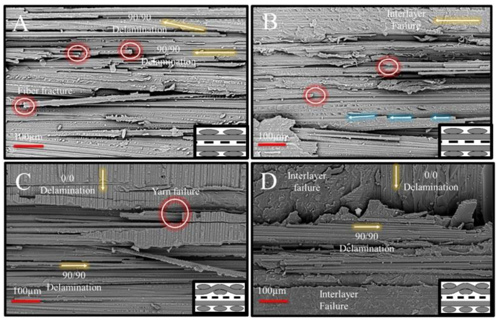
To identify the failure mechanisms, the focus was initially placed on the intermittent un-crimped 90° Jcs 09 00285 i009 yarns of the (90|90) adherent interface (Figure 8A). While the dominant failure mode in this region was 90/90 delamination, several other failure events occurred alongside the delamination, suggesting a more complicated progression. First, the intensity of the 90° yarn failures was notably high on the fracture surface, characterized by multiple fiber fractures (highlighted in red circles) and localized yarn splitting due to the separation of fiber blocks. Second, a change in the crack propagation direction was observed, particularly near areas exhibiting fiber fracture and yarn splitting. This indicates the coexistence of multiple failure modes during specimen failure, including 90/90 delamination, fiber fracture, yarn splitting, and shear failure. Additionally, the fracture surfaces showed no clear evidence suggesting that the transverse failure events directly caused the delamination. Therefore, it can be concluded that critical crack initiation responsible for yarn/yarn delamination originated elsewhere and propagated along the (90|90) interface, accompanied by the co-existence of 90° transverse failure and shear failure, potentially induced by specimen rotation.
The investigation of a similar region of interest in (90|X|90) (Figure 8B) suggested that the addition of nanofibers did not cause any significant changes in the overall appearance of the fracture surfaces when compared to (90|90). The only difference captured was the presence of nanofiber/resin composite regions on the 90/90 delamination surfaces instead of un-reinforced resin (Figure 8A). This observation suggested that although nanofibers were able to locally toughen the resin phase, this toughening was not sufficient to prevent the formation of transverse yarn failure and splitting events and increase the failure load (Table 4).
A crack jump location at a crimping site in the (90|90) adherent interface case is shown in Figure 8C, where yarn failure in the 0° yarns is visible. This observation suggests the susceptibility of the stronger 0° yarns to failure, influenced by both yarn crimping and the intense transverse cracking occurring in the neighboring 90° Jcs 09 00285 i010 yarns. Crimping locations appear to have been critically loaded during mechanical loading, serving as potential crack initiation sites. An important region of interest, where interlayer failure dominated the fracture surface except at the crimping location, is shown in Figure 8D. In this region, two interlayer failure zones—one at the upper 90° yarn and another at the lower 0° yarns—were separated by a critical yarn failure event occurring in the 90° yarns. This observation is also significant in understanding the effectiveness of nanofibers (Table 4) to mitigate transverse failure events, whether in un-crimped 90/90 interfaces or at the yarn intersection (crack jump locations). Given this limitation, no improvements in lap shear failure load were achieved, suggesting that while nanofibers may enhance specific interfacial properties, their influence on specific critical failure mechanisms, such as transverse cracking and yarn splitting, remained minimal (Table 4).

3.4. (0|90) and (0|X|90) Joint Interfaces

Previous investigations on (0|0) and (90|90) lap joint interfaces clearly indicated that yarn crimping locations were the most critical crack initiation sites due to the crimping inherent in the 8HS architecture. Additionally, it has been shown that transverse failure of the 90° yarns significantly impacts performance, arguably driven by the 0° yarns, which are aligned with the load path.
From this perspective, the mechanical test results suggested that the lap shear failure load of the (0|90) joint was 25–27% lower than that of the (0|0) and 90|90 joints. However, this strength loss was fully compensated by interleaving nanofibers at the joint, bringing it back to similar levels to those of the non-interlayered (0|0) and (90|90) joints (Table 4). The force vs. displacement curves also exhibited intermediate failure event marks at significantly earlier force and displacement values (Figure 9). To clarify the reasons for this strength drop with varying yarn architecture and the effects of interlayer toughening, the fracture surface analysis of the (0|90) samples was also conducted.
Similarly to previous cases, initial attention was given to the fracture surfaces of intermittent un-crimped 0/0 yarn Jcs 09 00285 i011 interface (Figure 10A). Two significant changes were observed: (i) a reduction in the mode II component of crack propagation and (ii) larger transverse fracture events on the 0/0 yarns compared to those in Figure 6A. Both observations strongly suggest a reduction in the fracture toughness at the intermittent 0/0 yarn interface sites of the (0|90) joint interface case. A similar region of interest in the 0/0 yarn lap of the (0|X|90) joint interface (Figure 10B), where significant interlayer failure was observed, suggested an improved ability of nanofibers to enhance delamination resistance at the 0/0 yarn interface sites. This observation was somewhat similar to the behavior seen in the (0|0) joint interface case.
The most striking effect of nanofibers was observed at the yarn intersection locations in the (0|90) joint interface. In Figure 10B, a failure location at the yarn intersection with similarity to Figure 6E is portrayed. The common feature between this location and Figure 6E is the presence of a resin-rich region Jcs 09 00285 i012 between the 0° and 90° yarns. However, it is interpreted that a direct crack propagation route exists through the split 0° fibers and excess resin. This route connects the lower 0° yarn, where the failure mode was 0/90 delamination (note the 90° marks over the warp 0° yarn, left half of Figure 10C), to the intermittent lap of the 90° yarns, which exhibited mode I-dominated 90/90 delamination. This observation suggests that the proximity of crimping and 0/90 yarn intersections facilitated frequent crack jumps at the joint interfaces. The resulting difference in mechanical test results indicates that these crack jumps had a tangible negative impact on lap shear strength. However, the nanofibrous interlayers played a crucial role in mitigating this effect: for the (0|X|90) joint interface (Figure 10D), unlike all previous cases, the nanofibrous interlayers provided significant resistance at the crack jump locations, ultimately preventing layer separation and leading a drastic increase in lap shear strength (Table 4).
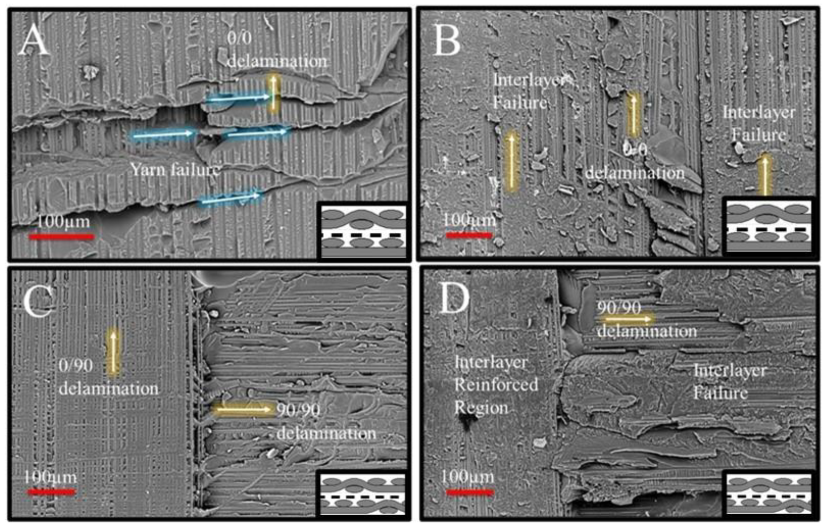
Figure 10. Fracture surfaces showing an intermittent un-crimped 0/0 yarn interface in (A) (0|90) and (B) (0|X|90) and a crimping region in (C) (0|90) and (D) (0|X|90). (yellow arrows indicate direction of main crack propagation).
Jcs 09 00285 g010
Fractographic analyses showed that while the yarn intersection locations are common in all cases, their impact and how the interleaving nanofibers interact with them varied depending on the joint interface configuration. Table 4 summarizes the case-by-case failure loads and observations.
From a broader perspective, the results of the fractographic analysis emphasize that the incorporation of nanofibers was particularly effective in mitigating mode II delamination at the yarn interfaces in both (0|0) and (0|90) configurations. Additionally, the interleaving strategy effectively addressed inherent challenges associated with layer-by-layer textile reinforcement, such as resin-rich regions forming between crimp locations. The crack-deflection capabilities of the nanofibrous veils appeared to disrupt these excess resin pockets, enhancing joint integrity. However, in the (90|90) configuration, the benefits of nanofiber reinforcement were less pronounced. This was attributed to premature local yarn failure initiated at yarn intersection sites, which occurred at a scale larger than that of the nanofiber layer. As a result, the toughening contribution of the interleaved veils was overshadowed, likely due to a mismatch in scale. Future work should therefore focus on optimizing the veil thickness to better match the size and geometry of the crimping features in various textile composite architectures, thereby enhancing their effectiveness in joint reinforcement. Matching the veil thickness to in situ crimp dimensions could maximize the toughening effects. Furthermore, exploring alternative base polymers for the nanofibrous veils may provide opportunities to tailor bond line properties and further enhance joint strength in diverse composite systems.

4. Conclusions

This study investigated the effects of nanofiber interleaving on the mechanical performance and failure mechanisms of co-cured composite lap joints with fiber orientation mismatch, a condition inherent to reinforcement architectures like 8HS fabric. The alternating dominance of the 90° and 0° yarns across layers provided a unique opportunity to evaluate how mismatches at the yarn level influence interface bonding.
Statistical analyses using ANOVA and ANOM confirmed that both fiber orientation and nanofiber interleaving significantly affect joint strength. ANOVA revealed strong main effects and significant interaction (p < 0.001), indicating that the benefits of nanofiber interleaving depend on fiber alignment. ANOM further identified the (0|90) configuration as the most sensitive to enhancement, with failure loads exceeding decision limits. These findings demonstrate that nanofiber interleaving is particularly effective in mitigating the strength reductions caused by orientation mismatches.
Fractography showed that while ply flipping can reduce ply-level mismatch, yarn-level interactions remain critical. In the (0|0) and (90|90) joints, crack initiation was localized near yarn crimping sites, yet both configurations exhibited comparable failure loads. The mismatched (0|90) joints, however, experienced significantly lower lap shear strength due to frequent crack jumps at yarn intersections and premature crack initiation. Nanofiber interleaving suppressed crack propagation at these critical sites, improved delamination resistance, and increased lap shear strength in the (0|0) and (0|90) joints by 12% and 25%, respectively. Fracture surface analysis confirmed more stable crack paths in nanofiber-enhanced joints, particularly along yarn interfaces. However, limited improvement was observed in mitigating local 90° yarn failure at yarn intersection edges, where matrix cracking dominated failure behavior.
Overall, nanofiber interleaving enhances the mechanical robustness of co-cured composite joints by improving adhesion and resisting crack propagation. It is especially beneficial in configurations compromised by fiber orientation mismatch due to its in situ adaptability. Future studies should explore veil design/choice optimization (polymer type, nanofiber diameter, veil thickness) and their effectiveness in other joint geometries or bonding test scenarios to maximize interfacial integrity.

Author Contributions

Conceptualization, M.P.; Data Curation, A.B.A.R., K.B. and M.P.; Formal Analysis, A.B.A.R., K.B. and M.P.; Funding Acquisition, M.P.; Investigation, A.B.A.R., K.B. and M.P.; Methodology, A.B.A.R., K.B. and M.P.; Project Administration, A.B.A.R., K.B. and M.P.; Resources, M.P.; Supervision, K.B. and M.P.; Validation, A.B.A.R., K.B. and M.P.; Visualization, A.B.A.R., K.B. and M.P.; Writing—Original Draft, A.B.A.R., K.B. and M.P.; Writing—Review and Editing, A.B.A.R., K.B. and M.P. All authors have read and agreed to the published version of the manuscript.

Funding

This work was supported by internal startup funding from the College of Engineering and Computer Science, California State University, Northridge.

Data Availability Statement

The original contributions presented in this study are included in the article. Further inquiries can be directed to the corresponding author.

Acknowledgments

The authors would like to thank Jesus Gonzales Barrera for his contributions to test specimen preparation. Appreciation is also extended to the Multi-Scale Materials Characterization Laboratory of Mechanical Engineering Department at CSUN for providing access to equipment for SEM imaging and mechanical testing.

Conflicts of Interest

The authors declare no conflicts of interest.

Nomenclature

8HSEight-Harness Satin.
{90/0} → Jcs 09 00285 i013Notation for an 8HS ply (no flip)—dominance of 90° yarns on the bottom surface and 0° yarns on the top surface.
{0/90} → Jcs 09 00285 i014Notation for an 8HS ply (flipped)—dominance of 0° yarns on the bottom surface and 90° yarns on the top surface.
XXantuLayr nanofiber interlayer—indicating that a nanofibrous veil was co-cured at the bond line.
(0|0)At the bond interface—both adherends have fibers/yarns dominantly aligned in the 0° direction (warp direction).
(90|90)At the bond interface—both adherends have fibers/yarns dominantly aligned in the 90° direction (weft direction).
(0|90)At the bond interface—one adherend has fibers/yarns dominantly aligned in the 90° direction (weft direction) and the other has fibers/yarns dominantly aligned in the 0° direction (warp direction).
(0|X|0)(0|0) interleaved with the X nanofiber interlayer at the interface.
(90|X|90)(90|90) interleaved with the X nanofiber interlayer at the interface.
(0|X|90)(0|90) interleaved with the X nanofiber interlayer at the interface.
SLJSingle-Lap Joint.
TATop Adherend—top substrate in the lap joint.
BABottom Adherend—bottom substrate in the lap joint.
0/0 delaminationDelamination at the zones of stacked 0° yarns, i.e., 0° yarn interaction sites
90/90 delaminationDelamination at the zones of stacked 90° yarns, i.e., 90° yarn interaction sites
0/90 delaminationDelamination at the zones of stacked 0 and 90° yarns, i.e., 0° and 90° yarn interaction sites

References

  1. Quan, D.; Farooq, U.; Zhao, G.; Dransfeld, C.; Alderliesten, R. Co-Cured Carbon Fibre/Epoxy Composite Joints by Advanced Thermoplastic Films with Excellent Structural Integrity and Thermal Resistance. Int. J. Adhes. Adhes. 2022, 118, 103247. [Google Scholar] [CrossRef]
  2. Antelo, J.; Akhavan-Safar, A.; Carbas, R.J.C.; Marques, E.A.S.; Goyal, R.; da Silva, L.F.M. Replacing Welding with Adhesive Bonding: An Industrial Case Study. Int. J. Adhes. Adhes. 2022, 113, 103064. [Google Scholar] [CrossRef]
  3. Bregar, T.; An, D.; Gharavian, S.; Burda, M.; Durazo-Cardenas, I.; Thakur, V.K.; Ayre, D.; Słoma, M.; Hardiman, M.; McCarthy, C.; et al. Carbon Nanotube Embedded Adhesives for Real-Time Monitoring of Adhesion Failure in High Performance Adhesively Bonded Joints. Sci. Rep. 2020, 10, 16833. [Google Scholar] [CrossRef]
  4. Katnam, K.B.; da Silva, L.F.M.; Young, T.M. Bonded Repair of Composite Aircraft Structures: A Review of Scientific Challenges and Opportunities. Prog. Aerosp. Sci. 2013, 61, 26–42. [Google Scholar] [CrossRef]
  5. Kim, G.-H.; Choi, J.-H.; Kweon, J.-H. Manufacture and Performance Evaluation of the Composite Hat-Stiffened Panel. Compos. Struct. 2010, 92, 2276–2284. [Google Scholar] [CrossRef]
  6. Quan, D.; Alderliesten, R.; Dransfeld, C.; Murphy, N.; Ivanković, A.; Benedictus, R. Enhancing the Fracture Toughness of Carbon Fibre/Epoxy Composites by Interleaving Hybrid Meltable/Non-Meltable Thermoplastic Veils. Compos. Struct. 2020, 252, 112699. [Google Scholar] [CrossRef]
  7. Quan, D.; Murphy, N.; Ivanković, A.; Zhao, G.; Alderliesten, R. Fatigue Delamination Behaviour of Carbon Fibre/Epoxy Composites Interleaved with Thermoplastic Veils. Compos. Struct. 2022, 281, 114903. [Google Scholar] [CrossRef]
  8. Quan, D.; Bologna, F.; Scarselli, G.; Ivankovic, A.; Murphy, N. Interlaminar Fracture Toughness of Aerospace-Grade Carbon Fibre Reinforced Plastics Interleaved with Thermoplastic Veils. Compos. Part A Appl. Sci. Manuf. 2020, 128, 105642. [Google Scholar] [CrossRef]
  9. Wang, S.; Katnam, K.B.; İnal, O.; Zou, Z.; Taylor, J.; Sprenger, S.; Potluri, P.; Soutis, C. The Static and Fatigue Failure of Co-Cured Composite Joints with Two-Scale Interface Toughening. Compos. Part B Eng. 2024, 287, 111867. [Google Scholar] [CrossRef]
  10. Dzenis, Y.A.; Reneker, D.H. Delamination Resistant Composites Prepared by Small Diameter Fiber Reinforcement at Ply Interfaces. US Patent No. 6265333 B1, 24 July 2001. [Google Scholar]
  11. Wu, X.F. Fracture of Advanced Polymer Composites with Nanofiber Reinforced Interfaces. Ph.D. Thesis, University of Nebraska-Lincoln, Lincoln, NE, USA, 2003. [Google Scholar]
  12. Wu, X.F. Fracture of Advanced Polymer Composites with Nanofiber Reinforced Interfaces: Fabrication, Characterization and Modeling; VDM Publishing: Saarbrücken, Germany, 2009. [Google Scholar]
  13. Chen, Q.; Zhao, Y.; Zhou, Z.P.; Rahman, R.; Wu, X.F.; Wu, W.D.; Xu, T.; Fong, H. Fabrication and mechanical properties of hybrid multi-scale epoxy composites reinforced with conventional carbon fiber fabrics surface-attached with electrospun carbon nanofiber mats. Compos. Part B Eng. 2013, 44, 1–7. [Google Scholar] [CrossRef]
  14. Chen, Q.; Zhang, L.F.; Zhao, Y.; Wu, X.F.; Fong, H. Hybrid Multi-Scale composites developed from glass microfiber fabrics and Nano-Epoxy resins containing electrospun glass nanofibers. Compos. Part B Eng. 2012, 43, 309–316. [Google Scholar] [CrossRef]
  15. Chen, Q.; Zhang, L.F.; Yoon, M.K.; Wu, X.F.; Arefin, R.H.; Fong, H. Preparation and evaluation of Nano-Epoxy composite resins containing electrospun glass nanofibers. J. Appl. Polym. Sci. 2012, 124, 444–451. [Google Scholar] [CrossRef]
  16. Chen, Q.; Zhang, L.F.; Rahman, A.; Zhou, Z.P.; Wu, X.F.; Fong, H. Hybrid Multi-Scale epoxy composite made of conventional carbon fiber fabrics with interlaminar regions containing electrospun carbon nanofiber mats. Compos. Part A Appl. Sci. Manuf. 2011, 42, 2036–2042. [Google Scholar] [CrossRef]
  17. Wu, X.F.; Rahman, A.; Zhou, Z.P.; Pelot, D.D.; Sinha-Ray, S.; Chen, B.; Payne, S.; Yarin, A.L. Electrospinning of Core–Shell nanofibers for interfacial toughening and Self-Healing of Carbon-Fiber/epoxy composites. J. Appl. Polym. Sci. 2013, 129, 1383–1393. [Google Scholar] [CrossRef]
  18. Sinha-Ray, S.; Pelot, D.D.; Zhou, Z.P.; Rahman, A.; Wu, X.F.; Yarin, A.L. Encapsulation of self-healing materials by co-Electrospinning, emulsion electrospinning, solution blowing and intercalation. J. Mater. Chem. 2012, 22, 9138–9146. [Google Scholar] [CrossRef]
  19. Dzenis, Y. Structural Nanocomposites. Science 2008, 319, 419–420. [Google Scholar] [CrossRef]
  20. Wu, X.F.; Yarin, A.L. Recent progress in interfacial toughening and damage Self-Healing of polymer composites based on electrospun and Solution-Blown nanofibers: An overview. J. Appl. Polym. Sci. 2013, 130, 2225–2237. [Google Scholar] [CrossRef]
  21. Palazzetti, R.; Zucchelli, A. Electrospun Nanofibers as Reinforcement for Composite Laminates Materials—A Review. Compos. Struct. 2017, 182, 711–727. [Google Scholar] [CrossRef]
  22. Mahato, B.; Lomov, S.V.; Shiverskii, A.; Owais, M.; Abaimov, S.G. A Review of Electrospun Nanofiber Interleaves for Interlaminar Toughening of Composite Laminates. Polymers 2023, 15, 1380. [Google Scholar] [CrossRef]
  23. Bilge, K.; Papila, M. 10-Interlayer Toughening Mechanisms of Composite Materials. In Toughening Mechanisms in Composite Materials; Woodhead Publishing Series in Composites Science and Engineering; Qin, Q., Ye, J., Eds.; Woodhead Publishing: Cambridge, UK, 2015; pp. 263–294. ISBN 978-1-78242-279-2. [Google Scholar]
  24. Beylergil, B.; Tanoğlu, M.; Aktaş, E. Effect of Polyamide-6,6 (PA 66) Nonwoven Veils on the Mechanical Performance of Carbon Fiber/Epoxy Composites. Compos. Struct. 2018, 194, 21–35. [Google Scholar] [CrossRef]
  25. Bilge, K.; Venkataraman, S.; Menceloglu, Y.Z.; Papila, M. Global and Local Nanofibrous Interlayer Toughened Composites for Higher In-Plane Strength. Compos. Part A Appl. Sci. Manuf. 2014, 58, 73–76. [Google Scholar] [CrossRef]
  26. Bilge, K.; Ozden-Yenigun, E.; Simsek, E.; Menceloglu, Y.Z.; Papila, M. Structural Composites Hybridized with Epoxy Compatible Polymer/MWCNT Nanofibrous Interlayers. Compos. Sci. Technol. 2012, 72, 1639–1645. [Google Scholar] [CrossRef]
  27. Zucchelli, A.; Focarete, M.L.; Gualandi, C.; Ramakrishna, S. Electrospun Nanofibers for Enhancing Structural Performance of Composite Materials. Polym. Adv. Technol. 2011, 22, 339–349. [Google Scholar] [CrossRef]
  28. Arpatappeh, F.A.; Manga, E.; Bilge, K.; Aydemir, B.E.; Gülgün, M.A.; Papila, M. Morphology Evolution of Self-Same Nanocomposites Hybridized with Jumbo-Sized Particles. J. Appl. Polym. Sci. 2022, 139, e53073. [Google Scholar] [CrossRef]
  29. Bilge, K.; Yorulmaz, Y.; Javanshour, F.; Ürkmez, A.; Yılmaz, B.; Şimşek, E.; Papila, M. Synergistic Role of In-Situ Crosslinkable Electrospun Nanofiber/Epoxy Nanocomposite Interlayers for Superior Laminated Composites. Compos. Sci. Technol. 2017, 151, 310–316. [Google Scholar] [CrossRef]
  30. Javanshour, F.; Bilge, K.; Raheman, A.B.A.; Papila, M. Stiffness of In-Situ Formed Interleaving Polymeric Nanofiber-Epoxy Nanocomposites. Open J. Compos. Mater. 2024, 14, 147–157. [Google Scholar] [CrossRef]
  31. Bilge, K.; Javanshour, F.; Raheman, A.B.; Papila, M. A Comparative Fractographic Analysis for the Effect of Polymeric Nanofiber Reinforcements on the Tensile Behavior of Multi-Layered Epoxy Nanocomposites. Polym. Eng. Sci. 2025, 65, 2343–2352. [Google Scholar] [CrossRef]
  32. Beckermann, G.W.; Pickering, K.L. Mode I and Mode II Interlaminar Fracture Toughness of Composite Laminates Interleaved with Electrospun Nanofibre Veils. Compos. Part A Appl. Sci. Manuf. 2015, 72, 11–21. [Google Scholar] [CrossRef]
  33. Magniez, K.; de Lavigne, C.; Fox, B.L. The Effects of Molecular Weight and Polymorphism on the Fracture and Thermo-Mechanical Properties of a Carbon-Fibre Composite Modified by Electrospun Poly (Vinylidene Fluoride) Membranes. Polymer 2010, 51, 2585–2596. [Google Scholar] [CrossRef]
  34. Esenoğlu, G.; Tanoğlu, M.; Barisik, M.; İplikçi, H.; Yeke, M.; Nuhoğlu, K.; Türkdoğan, C.; Martin, S.; Aktaş, E.; Dehneliler, S.; et al. Investigating the Effects of PA66 Electrospun Nanofibers Layered within an Adhesive Composite Joint Fabricated under Autoclave Curing. ACS Omega 2023, 8, 32656–32666. [Google Scholar] [CrossRef]
  35. Minosi, S.; Moroni, F.; Pirondi, A. Evaluation of XD 10 Polyamide Electrospun Nanofibers to Improve Mode I Fracture Toughness for Epoxy Adhesive Film Bonded Joints. Processes 2023, 11, 1395. [Google Scholar] [CrossRef]
  36. Rao, M.P.; Pantiuk, M.; Charalambides, P.G. Modeling the Geometry of Satin Weave Fabric Composites. J. Compos. Mater. 2009, 43, 19–56. [Google Scholar] [CrossRef]
  37. Bilge, K.; Yilmaz, B.; Papila, M. Sound-Tracking of Failure Events in Cross-Ply Composite Laminates under Tension. Compos. Struct. 2016, 153, 421–427. [Google Scholar] [CrossRef]
  38. Mahesh; Singh, K.K.; Rawat, P. Effect of (0°/90°) and (+45°/–45°) Plies Position on the Failure Modes and Acoustic Signals in Carbon Fiber Reinforced Polymer Laminates under Quasi-Static Tensile Loading. Mech. Adv. Mater. Struct. 2024, 31, 12013–12040. [Google Scholar] [CrossRef]
  39. Yasaee, M.; Bond, I.P.; Trask, R.S.; Greenhalgh, E.S. Mode II Interfacial Toughening through Discontinuous Interleaves for Damage Suppression and Control. Compos. Part A Appl. Sci. Manuf. 2012, 43, 121–128. [Google Scholar] [CrossRef]
  40. Yasaee, M.; Bond, I.P.; Trask, R.S.; Greenhalgh, E.S. Mode I Interfacial Toughening through Discontinuous Interleaves for Damage Suppression and Control. Compos. Part A Appl. Sci. Manuf. 2012, 43, 198–207. [Google Scholar] [CrossRef]
  41. Greenhalgh, E.S. (Ed.) Failure Analysis and Fractography of Polymer Composites; Woodhead Publishing in Materials: Cambridge, UK, 2009; ISBN 978-1-84569-217-9. [Google Scholar]
  42. Ufuk, R.; Bilge, K.; Kıral, B.E.; Ereke, M.; Karabeyoğlu, A. Fractographic Investigation of Cryogenic Temperature Mode-II Delamination Behavior of Filament Wound CFRP Laminates with Varied Resin Systems. J. Compos. Sci. 2023, 7, 450. [Google Scholar] [CrossRef]
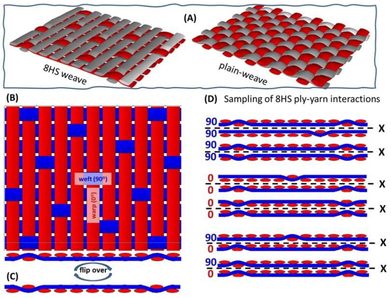
Figure 1. (A) Eight-harness satin (8HS) vs. plain-weave architecture; (B) 8HS woven fabric ply reference sketch, top view with warp (0°) yarns dominantly on top surface, and → denoted as {90/0}; (C) 8HS ply sketch; flipped-over cross-section view → denoted as {0/90}; (D) schematic representations of three primary ply-level interface configurations in composite laminates or bonded joints of 8HS plies, illustrating samples of potential yarn interactions at the ply interface: (from top to bottom) (90|90), (0|0), and (0|90) aligned yarns; X refers to the cases with the nanofibrous veil. Figures were prepared by open source software TexGen.v3.13.1.
Jcs 09 00285 g001
Figure 2. Experimental: (top) prepreg and Xantulyr integration, (bottom) lap joint design configuration adapted from ASTM D5868, and specimen gripped at UTM prior to testing.
Jcs 09 00285 g002
Figure 3. Statistical failure load analysis of single-lap joint (SLJ) specimens with and without nanofibrous interleaving across different substrate surface orientations: (left) interval plot of failure load; (right) analysis of variance (ANOVA) table.
Jcs 09 00285 g003
Figure 4. Statistical failure load analysis of single-lap joint (SLJ) specimens with and without nanofibrous interleaving across different substrate surface orientations: (left) main effects by two-way normal analysis of means (ANOM) compared to overall mean (green line) and decision limits at a significance level of α = 0.05 (red lines); (right) interaction plots by analysis of variance (ANOVA).
Jcs 09 00285 g004
Figure 7. Representative load vs. displacement curves for (90|90) and (90|X|90) joint interface samples.
Jcs 09 00285 g007
Figure 8. Fracture surfaces in (A) (90|90) and (B) (90|X|90) joint interface cases. A yarn crimping region with yarn failure both on 90° and 0° yarns in (C) (90|90) and (D) (90|X|90) joint interface cases. (red circle indicates local yarn failure at 90-degree yarns, blue arrows indicate crack jump across CF interfaces causing splitting).
Jcs 09 00285 g008
Figure 9. Representative load vs. displacement curves for the (0|90) and (0|X|90) joint interface samples and views from the fractured samples after testing.
Jcs 09 00285 g009
Table 1. Stacking sequences for adherends associated with the joint interface cases.
Bottom AdherendTop AdherendJoint Interfaces
{Jcs 09 00285 i001}6 →{90/0}6{Jcs 09 00285 i002}6 →{0/90}6(0|0)
(0|X|0)
{Jcs 09 00285 i003}6 →{0/90}6{Jcs 09 00285 i004}6 →{90/0}6(90|90)
(90|X|90)
{Jcs 09 00285 i005}6 →{90/0}6{Jcs 09 00285 i006}6 →{90/0}6(0|90)
(0|X|90)
Table 2. Categorical two-factor factorial design.
Categorical Factor# of LevelsLevels
Orientation3(0|0)–(0|90)–(90|90)
Nanofiber2No–Yes
Table 3. Single-lap joint (SLJ) test results for the joint interface configurations due to Table 1.
Joint Interface Notation
ANOVA Factorial Configurations [Orientation and Nanofiber]
(0|0)
[(0|0) & No]
(0|X|0)
[(0|0) & Yes]
(90|90)
[(90|90) & No]
(90|X|90)
[(90|90) & Yes]
(0|90)
[(0|90) & No]
(0|X|90)
[(0|90) & Yes]
ParametersMax_LoadMax_LoadMax_LoadMax_LoadMax_LoadMax_Load
Unit(N)(N)(N)(N)(N)(N)
(a)764974926752732359507028
(b)730288407283780164967071
(c)759988127519716154338031
(d)775883707606735659617999
(e)733884887477705558517803
Average752984007327733959387586
std. dev.217547343286379498
Table 4. Summary of single-lap joint (SLJ) performance and observed failure modes at representative yarn-level intersection regions across tested configurations.
ConfigurationFailure
Load (N)
% Strength
Change
Key Effects of Nanofibrous Interlayers
(0|X|0)
vs. (0|0)
8400 vs. ~750012%Increased 0/0 and 0/90 mode II delamination resistance; delayed crack coalescence due to excess resin blocks
(90|X|90)
vs. (90|90)
~7500 vs. ~75000%No suppression of dominant transverse failure modes, especially at yarn interfaces
(0|X|90)
vs. (0|90)
~7500 vs. ~600025%Most effective toughening; blocked crack jumps, and at yarn intersections, restored strength to (0|0)/(90|90) levels
Disclaimer/Publisher’s Note: The statements, opinions and data contained in all publications are solely those of the individual author(s) and contributor(s) and not of MDPI and/or the editor(s). MDPI and/or the editor(s) disclaim responsibility for any injury to people or property resulting from any ideas, methods, instructions or products referred to in the content.