Article

Free Vibration Characteristics of Functionally Graded Material (FGM) Beams on Three-Parameter Viscoelastic Foundation

1
College of Civil Engineering, Lanzhou Institute of Technology, Lanzhou 730050, China
2
Gansu Civil Engineering Science Research Institute Co., Ltd., Lanzhou 730010, China
*
Author to whom correspondence should be addressed.
J. Compos. Sci. 2025, 9(5), 215; https://doi.org/10.3390/jcs9050215
Submission received: 2 April 2025 / Revised: 27 April 2025 / Accepted: 27 April 2025 / Published: 28 April 2025

Abstract

:
This study numerically investigated free vibration characteristics of functionally graded material (FGM) beams on Winkler–Pasternak three-parameter elastic foundations using the modified generalized differential quadrature (MGDQ) method. To compare the effects of different beam theories on the predicted frequency responses, an nth order generalized beam theory was employed to establish the governing equations of the system’s dynamic model within the Hamilton framework. As a pioneering effort, a MATLAB (version 2021a) computational program implementing the MGDQ method was developed to obtain the free vibration responses of foundation-supported FGM beams. Parametric analyses were conducted through numerical simulations to systematically examine the influences of various factors, including beam theories, damping coefficients, foundation stiffness parameters, boundary conditions, gradient indices, and span-to-thickness ratios, on the natural frequencies and damping ratios of FGM beams. The findings provide an essential theoretical foundation for dynamic characteristic analysis and functional design of foundation-supported FGM beam structures.

1. Introduction

Dynamic characteristics analysis of beams on elastic foundations has garnered significant attention owing to their broad range of applications in civil engineering, rail transit, mechanical systems, and biomedical engineering [1,2,3,4]. Current elastic foundation models primarily include the Winkler–Pasternak [1], Kelvin [2], Vlasov [3], and Kerr [4] models. Among these, the Winkler–Pasternak two-parameter model is widely adopted by researchers [5,6], as it effectively characterizes both the compressive and shear interactions between the foundation and beam, thus offering a realistic representation of elastic foundation behavior. Notably, Thambiratnam & Zhuge [7] pioneered dynamic analysis of beams under moving loads on elastic foundations; they established a theoretical framework for time-domain response prediction. Kim & Roesset [8] further quantified the influence of frequency-independent damping in foundation models on dynamic responses, highlighting the necessity of viscosity characterization. Furthermore, the damping effects of foundation viscosity are unavoidable in practical engineering. For instance, studies [9,10,11] employed Euler beam theory (also known as classical beam theory (CBT)) to numerically investigate the vibration characteristics of homogeneous beams on viscoelastic foundations using diverse analytical approaches. Recent advances in viscoelastic modeling emphasize the importance of fractional calculus, as demonstrated by Sorrentino & Fasana [12], who integrated fractional derivative models into finite element analysis of vibrating systems, capturing frequency-dependent damping effects more accurately than classical integer-order approaches.
Functionally graded material (FGM) beams, featuring spatially continuous gradation of multiphase materials, enable tailored material parameter distributions. This customizable feature has led to innovative applications in cutting-edge fields, such as aerospace thermal protection systems and heterogeneous interfaces in energy equipment. Extending this concept to plate structures, a recent work [13] investigated free vibration of FGM plates on elastic foundations, revealing micromechanical model sensitivity in predicting mode shapes—a finding that underscores the need for refined modeling in FGM beam studies. Precise analysis of the dynamic behavior of FGM beams holds critical theoretical value for overcoming multi-objective optimization challenges under extreme conditions and ensuring operational safety, thus making it a frontier topic in smart material mechanics.
Existing research predominantly adopts forward analysis frameworks, combining analytical and numerical methods to explore the dynamic mechanisms of FGM beams [14,15,16,17,18,19,20,21,22,23,24,25,26]. In theoretical modeling, Simsek [14] pioneered a unified Lagrange frequency equation system encompassing seven shear deformation theories. Kahya et al. [15] developed finite element models for free vibration and buckling analysis based on Timoshenko’s first-order shear beam theory (FSBT). The integration of advanced viscoelastic models was facilitated by Lesieutre & Lee [16], who developed a finite element method with frequency-dependent constrained layer damping and demonstrated enhanced energy dissipation modeling capabilities for beam structures. For coupled-field analysis, some studies [17,18,19] systematically investigated vibration responses under thermo-mechanical multiphysical coupling. Pu Yu et al. [20] resolved the dynamic prediction challenges of porous FGM beams under hygro-thermo-mechanical coupling using the n-th order generalized beam theory (GBT) and Navier’s analytical method.
Some notable advancements in elastic foundation effects include the following: Ying et al. [21] established a free vibration model for FGM simply supported beams on elastic foundations using state-space methods based on 2D linear elasticity theory, while Pu Yu et al. [22] revealed the regulatory effects of Winkler–Pasternak foundation parameters on vibration modes via 2D differential quadrature methods. Zahedinejad [23] quantified thermal effects on spectral characteristics of foundation beams by integrating Reddy’s third-order shear theory (TBT) with differential quadrature techniques. Sun et al. [24] provided critical insights into memory-dependent behaviors through comparative analysis of constant-order versus variable-order fractional models, thus establishing theoretical foundations for selecting viscoelastic constitutive models in foundation-beam interactions. Deng et al. [25] pioneered quantitative stability evaluation of dual-FGM beam systems using the FSBT-based dynamic stiffness matrices. Recently, Pu Yu et al. [26] employed GBT and a modified generalized differential quadrature (MGDQ) method to numerically study the vibration characteristics of FGM beams on elastic foundations under initial axial loads; specifically, they unveiled the dual coupling between buckling and vibrational static-dynamic behaviors.
Moreover, Duc et al. [27] developed a nonlinear dynamic model for piezoelectric FGM hyperbolic shells embedded in elastic foundations under damping-thermal-electrical-mechanical loads. Using stress functions, the Galerkin method, and the fourth-order Runge-Kutta method, they solved the nonlinear vibration problem, emphasizing the effects of material properties and coupled loads on nonlinear dynamic responses. Loghman et al. [28] considered the viscoelastic internal damping of materials and, based on modified couple stress theory and Von Kármán nonlinear relations, applied finite difference and finite element methods to analyze the influence of fractional damping coefficients, scale parameters, and material gradient indices on the nonlinear free and forced vibration characteristics of FGM microbeams. Despite these advancements, research on the vibration behavior of FGM beams on viscoelastic foundations remains limited.
This work introduces a novel approach by incorporating the foundation’s damping effect from an energy dissipation perspective. As an exploratory effort, we developed the system’s dynamic model based on n-th order GBT and Hamilton’s principle. Through the introduction of boundary condition control parameters, we achieved unified derivation of modified weighting coefficients for beams with three boundary configurations: clamped-clamped (C-C), clamped-supported (C-S), and supported-supported (S-S). This study pioneers the application of the MGDQ method to numerically solve the frequency response of free vibrations in FGM beams resting on Winkler–Pasternak three-parameter elastic foundations. Finally, comprehensive parametric analyses were conducted to investigate the effects of multiple factors, including beam theories, damping coefficients, foundation stiffness parameters, boundary conditions, gradient indices, and span-to-thickness ratios, on the frequency characteristics of FGM beams.

2. Governing Differential Equations

2.1. Governing Equations of Dynamic System

As illustrated in Figure 1, consider an FGM beam resting on a three-parameter viscoelastic foundation, with length L, width B, and height H. The beam comprises a ceramic-rich upper surface and a metal-rich lower surface. A Cartesian coordinate system is defined such that the x-axis aligns with the beam’s longitudinal direction; the z-axis corresponds to the thickness direction, and the x-y plane coincides with the geometric midplane of the beam. The beam is subjected to a transversely distributed dynamic load q(x,t). The foundation is characterized by three parameters: the Winkler stiffness coefficient kw, Pasternak shear stiffness coefficient kp, and transverse viscous damping coefficient cd.
The material properties (elastic modulus E, Poisson’s ratio ν, and density ρ) vary continuously along the thickness direction (z) following the Voigt-type power-law mixture model. These graded properties are expressed as:
P ( z ) = P m + ( P c P m ) ( 1 2 + z h ) p ,
where p denotes the material gradient index, and the subscripts m and c represent the metallic and ceramic constituents, respectively.
To compare the predictive differences among various beam theories regarding free vibration responses, this study employs an n-th order GBT framework, where the displacement field at any point within the beam can be expressed as:
u x ( x , z , t ) = u ( x , t ) z w x + f ( z ) [ φ ( x , t ) + w x ] u y ( x , z , t ) = 0 u z ( x , z , t ) = w ( x , t ) ,
f ( z ) = z h 2 n ( 2 z h ) n ,
where u(x,t) denotes the axial displacement at time t; φ(x,t) represents the cross-sectional rotation; and ω(x,t) corresponds to the generalized transverse displacements associated with the i-th deformation mode. The function f(z) represents the transverse shear stress shape function corresponding to the n-th order GBT [29]. When shear deformation effects are neglected (i.e., n = 1), the GBT reduces to the CBT; when a parabolic distribution of shear strain is assumed through the beam thickness (i.e., n = 3), the GBT degenerates into Timoshenko Beam Theory (TBT). For a constant shear strain assumption across the beam thickness (i.e., n = ∞).
Based on the geometric equations of small deformation, the expressions for non-zero strain components can be derived as:
ε x = u x z 2 w x 2 + f ( z ) ( φ x + 2 w x 2 ) γ x z = g ( z ) ( w x + φ ) ,
where g(z) denotes the transverse shear strain shape function.
The constitutive relations are expressed as:
σ x = E ( z ) ε x τ x z = G ( z ) γ x z ,
G ( z ) = E ( z ) 2 1 + μ ( z ) ,
where G(z) represents the shear modulus varying along the thickness direction.
The variation in the system’s kinetic energy (δT), strain energy (δVε), and external work and viscoelastic foundation potential (δV) are expressed as:
δ T = 0 L A ρ ( z ) ( u x t δ u x t + u z t δ u z t ) d A d x ,
δ V ε = 0 L A ( σ x δ ε x + τ x z δ γ x z ) d A d x ,
δ V = 0 L ( k w w c d w t + q ) δ w + k p w x δ w x d x .
Applying Hamilton’s principle:
t 1 t 2 ( δ T δ V ε δ V ) d t = 0 .
Substituting Equations (2)–(9) into Equation (10), followed by simplification and rearrangement, yields the governing dynamic equation of the system:
S 1 d 2 u d x 2 + S 3 d 2 φ d x 2 S 7 d 3 w d x 3 I 0 u ¨ I 2 φ ¨ I 6 d w ¨ d x = 0 , S 3 d 2 u d x 2 + S 6 d 2 φ d x 2 S 0 ( φ + d w d x ) + S 8 d 3 w d x 3 I 2 u ¨ I 5 φ ¨ I 7 d w ¨ d x = 0 , S 7 d 3 u d x 3 S 8 d 3 φ d x 3 + S 9 d 4 w d x 4 + S 0 ( d φ d x + d 2 w d x 2 ) k w w + k p d 2 w d x 2 c d w ˙ I 0 w ¨ + I 6 d u ¨ d x + I 7 d φ ¨ d x I 8 d 2 w ¨ d x 2 = q ( x , t ) ,
The elastic coefficients are defined as:
S i = A E ( z )   1 , z , f , z 2 , z f , f 2 d A , ( i = 1 , 2 , 6 ) , S 0 = A G ( z ) g 2 d A ,   S 7 = S 2 S 3 ,   S 8 = S 6 S 5 , S 9 = 2 S 5 S 4 S 6 .
The inertia coefficient is defined as:
I i = A ρ ( z ) 1 ,   z ,   f ,   z 2 ,   z f ,   f 2 d A , ( i = 0 , 1 , 5 ) , I 6 = I 2 I 1 ,   I 7 = I 5 I 4 ,   I 8 = 2 I 4 I 3 I 5 .
Equation (11) governs the forced vibration of a three-parameter viscoelastic foundation-FGM beam under a transverse dynamic load q(x,t). Specific cases include free damped vibration (q(x,t) = 0) and free undamped vibration (q(x,t) = 0 and Cd = 0). Notably, the elastic and inertia coefficients embed tension/compression-shear-bending coupling effects.
Based on Hamilton’s principle, the boundary conditions derived from Equation (10) are simplified and categorized into three beam configurations for investigation:
(i) Clamped-Clamped (C-C):
u = φ = w = d w d x = 0 ,   x = 0   and   x = L .
(ii) Clamped-Supported (C-S):
u = φ = w = d w d x = 0 ,   x = 0 . d u d x = d φ d x = w = d 2 w d x 2 = 0 ,   x = L .
(iii) Supported-Supported (S-S):
d u d x = d φ d x = w = d 2 w d x 2 = 0 ,   x = 0 and   x = L .

2.2. Governing Equations of Damped Free Vibration System

For a freely vibrating FGM beam, the displacement components can be assumed as:
u ( x , t ) φ ( x , t ) w ( x , t ) = U ( x ) Ψ ( x ) W ( x ) exp i ω t ,
where ω is the complex characteristic frequency of the damped free vibration of the FGM beam; U(x), Ψ(x), W(x) are the displacement mode shape functions; and i = 1 is the imaginary unit.
By setting q(x,t) = 0 and substituting Equation (17) into Equation (11), the governing differential equation for the free vibration of the FGM beam on a three-parameter viscoelastic foundation is derived as shown below:
S 1 d 2 U d x 2 + S 3 d 2 Ψ d x 2 S 7 d 3 W d x 3 + ω 2 ( I 0 U + I 2 Ψ + I 6 d W d x ) = 0 , S 3 d 2 U d x 2 + S 6 d 2 Ψ d x 2 S 0 ( Ψ + d W d x ) + S 8 d 3 W d x 3 + ω 2 ( I 2 U + I 5 Ψ + I 7 d W d x ) = 0 , S 7 d 3 U d x 3 S 8 d 3 Ψ d x 3 + S 9 d 4 W d x 4 + S 0 ( d Ψ d x + d 2 W d x 2 ) k w W + k p d 2 W d x 2 i c d ω W + ω 2 ( I 0 W I 6 d U d x I 7 d Ψ d x + I 8 d 2 W d x 2 ) = 0 .
Clearly, the governing differential equation (Equation (18)), combined with the boundary equations (Equations (14)–(16)), forms a boundary value problem for the damped free vibration of the FGM beam on a three-parameter viscoelastic foundation under three typical boundary conditions.

3. MGDQ Method for Solving for Complex Characteristic Frequencies

3.1. Introduction of Beam Boundary Condition Control Parameters

First, based on the generalized differential quadrature method [29], the k-th order derivatives of the displacement mode shape functions at discrete nodes xi can be expressed as:
d k d x k U ( x ) Ψ ( x ) W ( x ) x = x i = j = 1 N C i j ( k ) U j ( x j ) Ψ j ( x j ) W j ( x j ) ,
where C i j ( k ) is the weighting coefficient for the k-th order derivative of the displacement mode shape function, and N is the total number of discrete nodes.
Second, the weighting coefficients for the 0-th order derivative of any unknown function at x = 0 and x = L are defined as:
C 1 j ( 0 ) = 1 ( j = 1 ) 0 ( e l s e ) ;   C N j ( 0 ) = 1 ( j = N ) 0 ( e l s e ) .
Using these definitions, the boundary equations (Equations (14)–(16)) for C-C, C-S, and S-S beams, respectively, can be uniformly discretized via the GDQ method as:
j = 1 N C 1 j ( n 0 ) U j = 0 j = 1 N C 1 j ( n 0 ) Ψ j = 0 W 1 = 0 j = 1 N C 1 j ( n 0 + 1 ) W j = 0 ,   j = 1 N C N j ( n 1 ) U j = 0 j = 1 N C N j ( n 1 ) Ψ j = 0 W N = 0 j = 1 N C N j ( n 1 + 1 ) W j = 0 ,
where n0 and n1 are the boundary condition control parameters. By assigning n0 = 0 or 1, and n1 = 0 or 1, the boundary conditions are defined as follows: n0 = 0 and n1 = 0 for the C-C beam; n0 = 0 and n1 = 1 for the C-S beam; and n0 = 1 and n1 = 0 for the S-S beam.

3.2. Weighting Coefficients in the MGDQ Method

To address the case wherein the total number of discretized equations exceeds the number of unknown displacements (thereby preventing a direct conversion to an eigenvalue problem), this study introduces improved weighting coefficients for the displacement mode shape functions under C-C, C-S, and S-S boundaries. These coefficients are derived [29] as:
P i j ( k ) = C i j ( k ) + C i 1 ( k ) C U K   1 + C i N ( k ) C U K N C U N Q i j ( k ) = P i j ( k ) R i j ( k ) = C i j ( k ) + C i 2 ( k ) C W K   1 + C i ( N 1 ) ( k ) C W K N C W N ,
C U K 1 = C 1 N ( n 0 ) C N j ( n 1 ) C N N ( n 1 ) C 1 j ( n 0 ) C U K N = C N 1 ( n 1 ) C 1 j ( n 0 ) C 11 ( n 0 ) C N j ( n 1 ) C U N = C 11 ( n 0 ) C N N ( n 1 ) C 1 N ( n 0 ) C N 1 ( n 1 ) ,
C W K 1 = C 1 ( N 1 ) ( n 0 + 1 ) C N j ( n 1 + 1 ) C N ( N 1 ) ( n 1 + 1 ) C 1 j ( n 0 + 1 ) C W K N = C N 2 ( n 1 + 1 ) C 1 j ( n 0 + 1 ) C 12 ( n 0 + 1 ) C N j ( n 1 + 1 ) C W N = C 12 ( n 0 + 1 ) C N ( N 1 ) ( n 1 + 1 ) C 1 ( N 1 ) ( n 0 + 1 ) C N 2 ( n 1 + 1 ) ,
where P i j ( k ) , Q i j ( k ) , and R i j ( k ) are the improved weighting coefficients for the m-th order derivatives of the displacement mode shape functions U(x), Ψ(x), W(x), respectively, at internal nodes, x = 0, and x = L, respectively.

3.3. Unified Discretized Equations via the MGDQ Method

Applying the MGDQ method to discretize Equation (18), the unified discretized equations for C-C, S-S, and C-S boundary beams are obtained as follows:
S 1 j = 2 N 1 P i j ( 2 ) U j + S 3 j = 2 N 1 Q i j ( 2 ) Ψ j S 7 j = 3 N 2 R i j ( 3 ) W j + ω 2 I 0 U i + I 2 Ψ i I 6 j = 3 N 2 R i j ( 1 ) W j = 0 ,   ( i = 2 , 3 , , N 1 ) ,
S 3 j = 2 N 1 P i j ( 2 ) U j + S 6 j = 2 N 1 Q i j ( 2 ) Ψ j + S 8 j = 3 N 2 R i j ( 3 ) W j S 0 Ψ i S 0 j = 3 N 2 R i j ( 1 ) W j + ω 2 I 2 U i + I 5 Ψ i + I 7 j = 3 N 2 R i j ( 1 ) W j = 0 ,   ( i = 2 , 3 , , N 1 ) ,
S 7 j = 2 N 1 P i j ( 3 ) U j S 8 j = 2 N 1 Q i j ( 3 ) Ψ j + S 9 j = 3 N 2 R i j ( 4 ) W j + S 0 j = 2 N 1 Q i j ( 1 ) Ψ j + j = 3 N 2 R i j ( 2 ) W j k w W i i c d ω W i + k p j = 3 N 2 R i j ( 2 ) W j + ω 2 I 0 W i I 6 j = 2 N 1 P i j ( 1 ) U j I 7 j = 2 N 1 Q i j ( 1 ) Ψ j + I 8 j = 3 N 2 R i j ( 2 ) W j = 0 ,   ( i = 3 , 4 , , N 2 ) .

3.4. Complex Characteristic Frequency Equation

After discretization, the total number of algebraic equations in the system equals the number of unknown displacement mode shape quantities (3N − 8). This system can be expressed as a matrix equation:
[ K ] + i ω [ C ] + ω 2 [ M ] X = 0 , X = { U 2 , U 3 , , U N 1 , Ψ 2 , Ψ 3 , , Ψ N 1 , W 3 , W 4 , , W N 2 } T ,
where K is the sub-stiffness matrix, C is the sub-damping matrix, M is the sub-mass matrix, and X is the nodal displacement vector.
The non-trivial solution condition for Equation (28) yields the complex characteristic frequency equation:
det [ K ] + i ω [ C ] + ω 2 [ M ] = 0 .
Solving Equation (29) provides the frequency response of the damped free vibration of the FGM beam.
For generality, the following non-dimensional parameters are adopted:
λ = L h ,   K w = k w L 4 E c I ,   K p = k p L 2 E c I ,   C d = c d L 2 E c I ρ c A ,   Ω = ω L 2 ρ c A E c I ,   ω ¯ = Ω ( ζ ± i 1 ζ 2 ) ,   Ω R = Ω ζ ,   Ω I = Ω 1 ζ 2 ,   δ = Ω R ,
where λ is the span-to-thickness ratio, Kw and Kp are non-dimensional foundation stiffness coefficients, Cd is the non-dimensional viscous external damping coefficient, I is the moment of inertia, A is the cross-sectional area, Ω is the undamped natural frequency, ΩR is the real part of and reflects the damping-induced decay, ΩI is the imaginary part of ω ¯ and represents the underdamped natural frequency, ζ is the damping ratio, and δ is the decay coefficient.
From the non-dimensional frequency definition in Equation (30), the real part of A is evidently negative, reflecting the influence of the external damping on the decay characteristics of the displacement response. When 0 < ζ < 1, the imaginary part of ω ¯ corresponds to the underdamped natural frequency, when ζ = 1, the system reaches the critical damping state, and when ζ > 0, the system is in an overdamped state.

4. Analysis and Discussion

In the examples considered in this study, N was taken as 17. An FGM beam composed of metal and ceramic was considered, with the following physical coefficients: Em = 70 GPa; ρm = 2702 kg/m3; Ec = 380 GPa; ρc = 3960 kg/m3; and μm = μc = 0.3 [20].

4.1. Validation of Numerical Results

To address the lack of data on the natural frequencies of FGM beams under viscoelastic damping effects, this study established a multi-dimensional validation framework. First, theoretical self-consistency verification was performed by degenerating the three-parameter foundation model into the classical Euler–Bernoulli beam (Kw = Kp = Cd = 0) under a short and thick beam condition with a λ of 5 to establish a baseline model. Subsequently, the numerical convergence was verified. As shown in Table 1, when Reddy’s third-order shear deformation theory (TBT, n = 3) was adopted and the dimensionless frequency definition was consistent with [14], and the relative errors of the dimensionless fundamental frequencies under C-C and S-S boundary conditions were both less than 0.5%, thereby significantly outperforming the 1.2% error level of the traditional differential quadrature method. This dual verification mechanism not only confirmed the computational stability of the MGDQ algorithm under geometrically constrained conditions but also revealed the physical consistency of the viscoelastic parameter modeling in this study, thus providing a reliable numerical benchmark for subsequent research on complex damping scenarios.

4.2. Influence of GBT Order n on Output Response Parameters

Next, the influence of the GBT order n on the free vibration response parameters of the three-parameter viscoelastic foundation FGM beam was explored, considering p = 1, λ = 5, Kw = 25, Kp = 5, and Cd = 10. Figure 2 illustrates the relationship curves of the dimensionless characteristic fundamental frequency (imaginary part ΩI, real part ΩR, and damping ratio ζ versus the GBT order n) for a clamped FGM short beam in an underdamped state.
From Figure 2a, it can be observed that ΩI exhibited minor fluctuations and gradually stabilized as the positive integer n increased, eventually approaching the prediction of the FSBT. The maximum ΩI value occurred at n = 2, and the minimum at n = 3, with an extreme difference of 0.43006. Additionally, for λ = 5 (a short and thick beam), the CBT neglected the effects of shear deformation, thereby overestimating the overall beam stiffness. Compared to the FSBT and TBT, the CBT overestimated ΩI (underestimating the period of underdamped decay vibration in the FGM beam). From Figure 2b, unlike the undamped free vibration, the real part ΩR of the fundamental frequency in the underdamped state was negative, indicating amplitude decay due to damping. Figure 2b,c show that, except for n = 1, the variations in the predicted values of ΩR and ζ were negligible with changes in n. However, the CBT significantly overestimated ΩR (underestimating the decay coefficient δ), thereby overestimating the amplitude; furthermore, it underestimated ζ, leading to an overestimation of the fundamental frequency ΩI. Compared with the TBT, the relative errors in ΩR and ζ predicted by the CBT reached 13.96% and 13.81%, respectively, which are not negligible.

4.3. Influence of Other Factors on Output Response Parameters

All examples considered herein adopted TBT to explore the influence of parameters, such as beam boundary conditions Cd, p, λ and foundation elastic stiffness on the free vibration response parameters of the FGM beam. Figure 3 describes the relationships between ΩI, ΩR, and ζ, and Cd for FGM beams under the three boundary conditions. With given parameters p = 1, λ = 20, Kw = 25, Kp = 5, the following observations were made.
From Figure 3a: ΩI monotonically decreased as Cd increased. When Cd was equal to critical damping Ccr, ΩI reached its minimum value. Increasing Cd further led to an overdamped state, where ΩI approached zero, thereby indicating purely decaying motion of the beam. Under different boundary conditions, ΩI was largest for C-C beams, intermediate for C-S beams, and smallest for S-S beams. The values of Ccr also varied across the boundary conditions, with C-C beams having the highest Ccr, S-S beams the lowest, and C-S beams falling in between.
From Figure 3b: In the underdamped stage, ΩR was negative for all three boundary conditions and decreased linearly with increasing Cd. This implies that the decay coefficient increased with Cd, reflecting a gradual reduction in the vibrational energy. In other words, the underdamped free vibration of the FGM beam manifested as an amplitude-decaying motion, with densely packed linear segments in the ΩRCd plot.
From Figure 3c: ζ of the three boundary-conditioned FGM beams increased linearly with Cd. For small damping (e.g., Cd < 5), boundary conditions had limited influence on ζ. For larger damping (e.g., Cd > 10), at the same Cd value, the S-S beams exhibited the highest ζ, C-C beams the lowest, and C-S beams falling in between.
Figure 4 shows the relationship curves of ΩI, ΩR, and ζ versus Cd for clamped FGM beams with different gradient index values. The parameters were set as λ = 20, Kw = 25, and Kp = 5.
From Figure 4a: For p = 0, 0.2, 1, and 10, ΩI decreased monotonically with increasing Cd in the underdamped stage until ΩI = 0 at their respective critical damping states. At the same Cd, a larger p resulted in a smaller ΩI and lower Ccr. When the FGM beam entered the overdamped state, ΩI = 0.
From Figure 4b: At Cd = 0, ΩR = 0. In the underdamped stage (0 < Cd < Ccr), ΩR was negative and decreased linearly with Cd. For the same Cd, a larger p led to a smaller ΩR. In the overdamped stage (Cd > Ccr), ΩR assumed two negative real numbers, and the ΩRCd curves opened to the right with significant separation, indicating a pronounced influence of p on displacement decay. Notably, larger p-values resulted in wider curve openings. Furthermore, Ccr corresponded to the abscissa of the intersection point between the underdamped linear segment and overdamped curve segment of ΩRCd.
From Figure 4c: ζ increased linearly with Cd. For small damping (e.g., 0 < Cd < 2), the ζCd linear segments were densely packed, suggesting a limited influence of p on ζ. However, for large damping (e.g., Cd > 20), the linear segments diverged significantly, highlighting a strong dependence of ζ on p.
In general, small damping (e.g., Cd < 5) had a negligible effect on the natural frequencies and could be ignored in routine calculations. However, the influence of small damping on amplitude decay could not be neglected, as the amplitudes diminished exponentially.
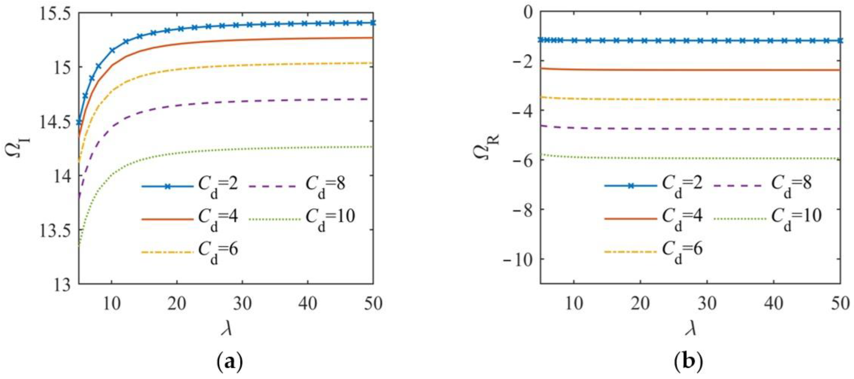
Figure 5 illustrates the relationship curves of ΩI and ΩR versus λ for a clamped-simply supported FGM beam in an underdamped state, with parameters p = 1, Kw = 25, and Kp = 5.
From Figure 5a: As λ increased, the ΩI curves initially rose significantly. When λ > 20, the increase in ΩI slowed down, indicating that the period of underdamped decay vibration decreased with λ, but became less sensitive for λ > 20. Additionally, for the same λ, a larger Cd resulted in a smaller ΩI.
From Figure 5b: The ΩRλ curves are nearly flat, suggesting that λ had minimal influence on the amplitude decay. For the same λ, a larger Cd led to a smaller ΩR (i.e., a larger decay coefficient δ), thereby accelerating the amplitude attenuation.
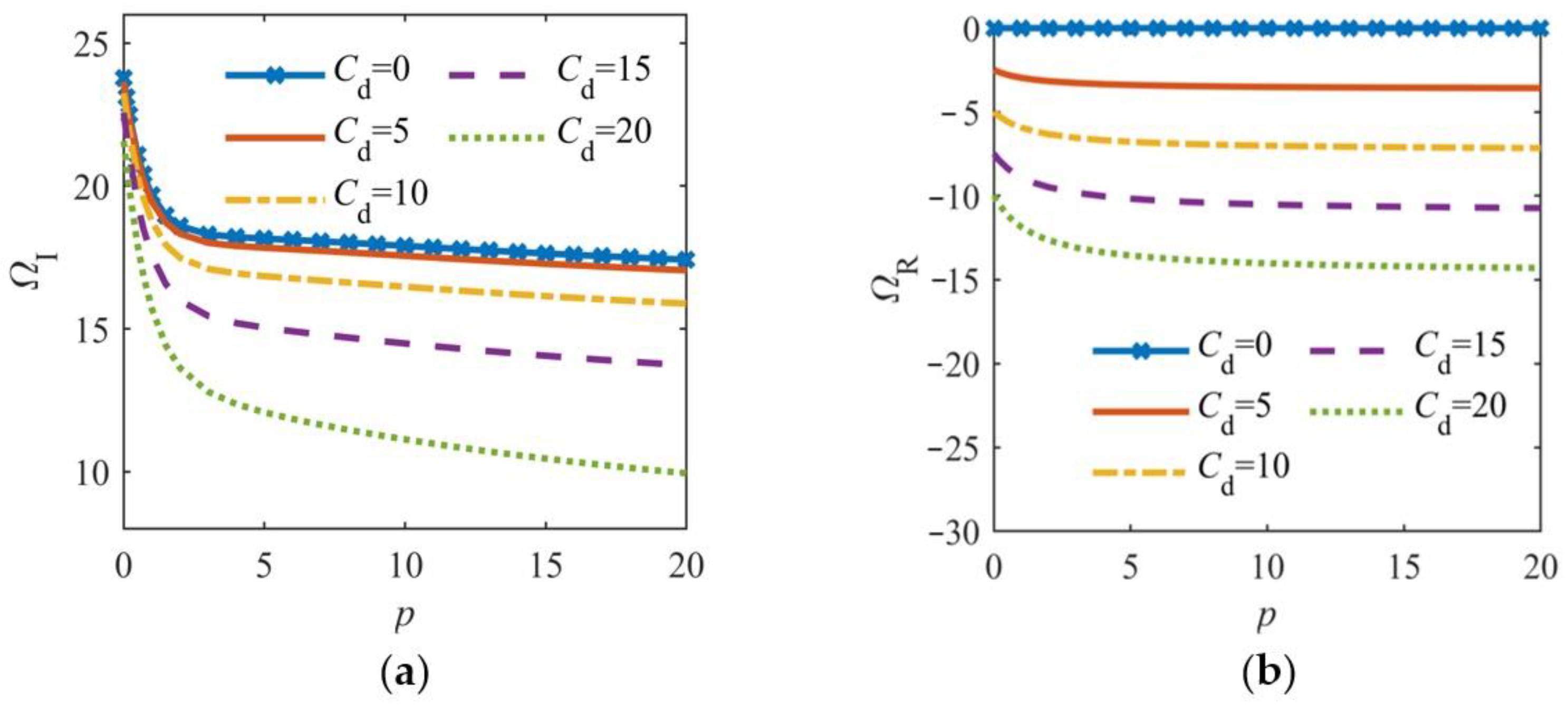
Figure 6 shows the relationship curves of ΩI and ΩR versus p for a clamped FGM beam in an underdamped state, with parameters λ = 20, Kw = 25, and Kp = 5.
From Figure 6a: The ΩI curves monotonically decreased as p increased (i.e., the ceramic content decreased). The most significant reduction occurred in the range 0 ≤ p ≤ 2, which could be attributed to the rapid weakening of the FGM beam’s overall stiffness due to the sharp decline in its alumina (Al2O3) content.
From Figure 6b: When Cd = 0, ΩR = 0 (a horizontal line), indicating undamped free vibration with a constant amplitude. With damping, ΩR decreased with p, most notably in the range 0 ≤ p ≤ 2. For p > 2, the decrease in ΩR slowed down, reflecting that amplitude attenuation diminished gradually as the ceramic content reduced further.
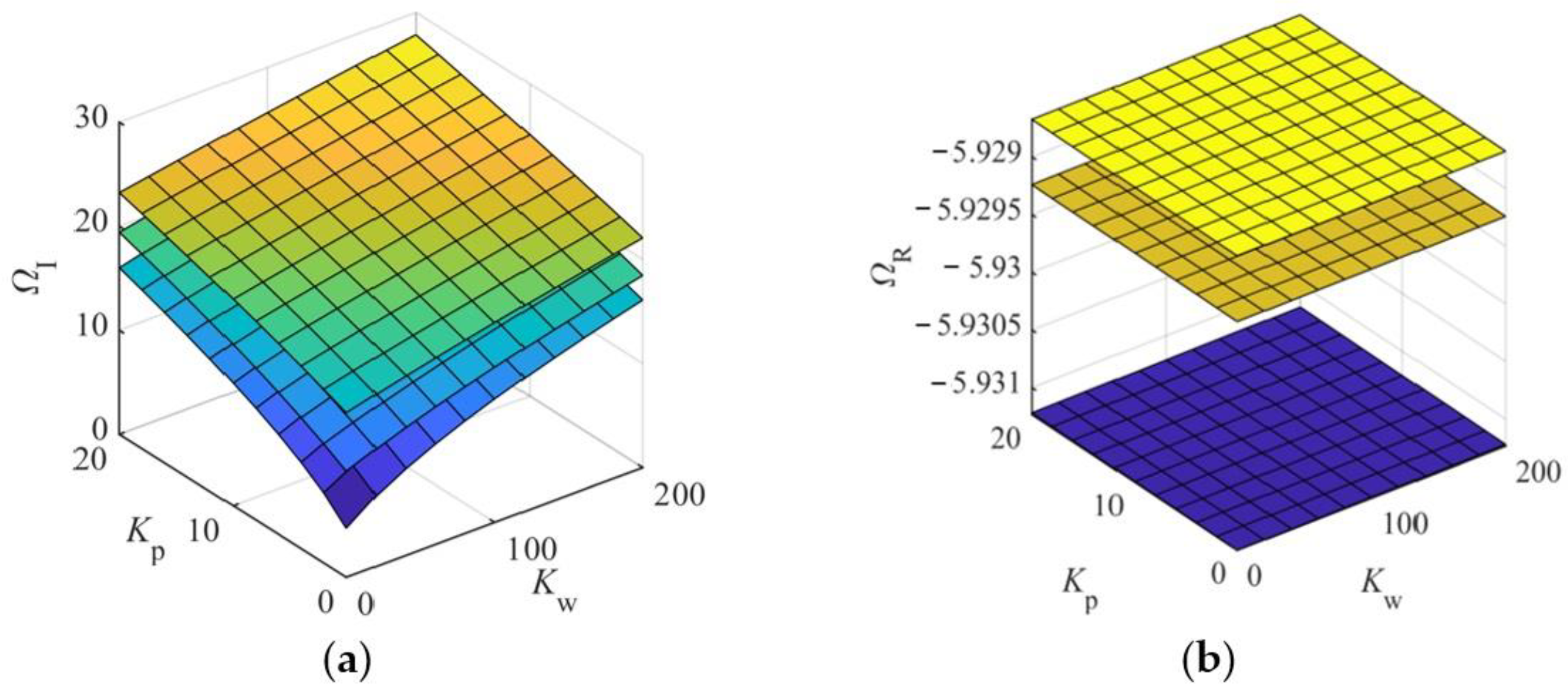
Figure 7 illustrates the relationship surfaces of ΩI and ΩR versus the Winkler–Pasternak foundation elastic stiffness coefficients Kw and Kp for the three typical boundary conditions (C-C, C-S, S-S) of the FGM beams in an underdamped state, with parameters p = 1, λ = 20, and Cd =10.
From Figure 7a: As Kw and Kp increased, ΩI rose, leading to a gradual reduction in the period of underdamped decay vibration. For a given foundation elastic stiffness, the ΩI surface values were significantly higher for the C-C boundaries, intermediate for C-S boundaries, and lowest for S-S boundaries. This was attributed to the enhanced equivalent stiffness of the beam structure under strongly constrained boundaries, which would increase the vibrational frequency.
From Figure 7b: The ΩR surfaces for all three boundary conditions are flat planes, indicating that increasing the foundation elastic stiffness had no effect on amplitude attenuation. Additionally, the ΩR values were slightly lower for the C-C boundaries, slightly higher for the S-S boundaries, and intermediate for the C-S boundaries. However, the differences in ΩR across the boundaries were minimal, reaffirming that the boundary conditions had a negligible influence on the amplitude attenuation in the underdamped states.
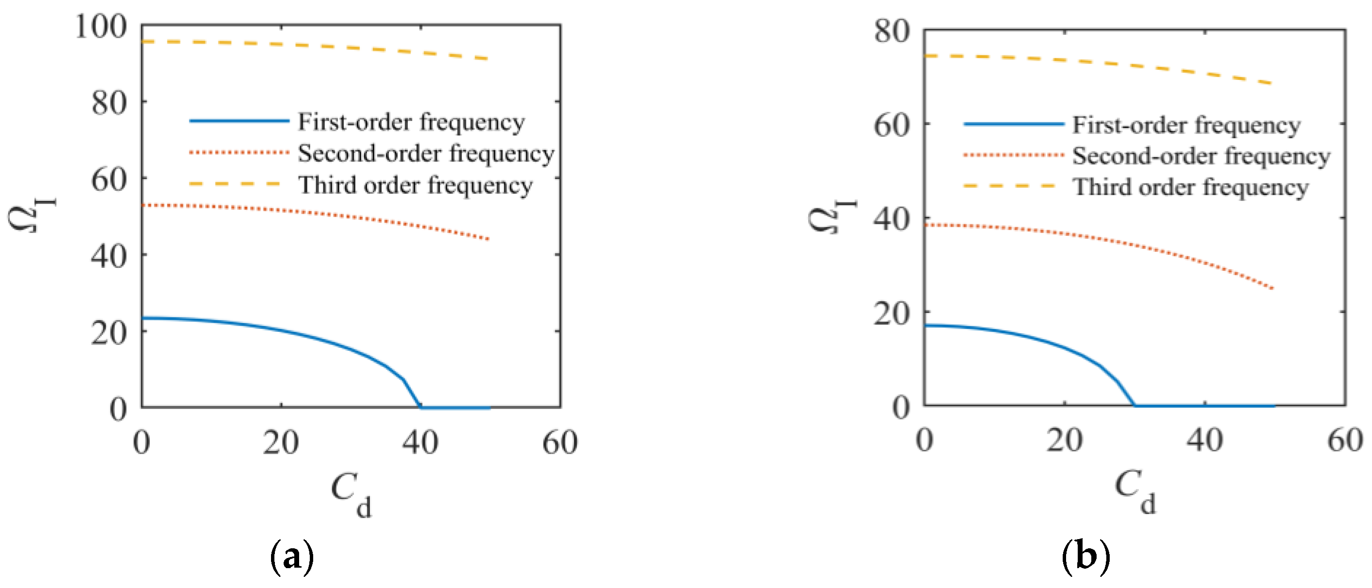
Figure 8 shows the relationship curves of ΩI versus Cd for the clamped (C-C) and simply-supported (S-S) FGM beams, with parameters p = 1, λ = 20, Kw = 100, and Kp = 10.
The first three frequencies of the FGM beams under both these boundary conditions decreased gradually with increasing Cd. The first-order frequency decreased most rapidly, reaching zero at Ccr, after which it remained at zero in the overdamped state. However, the second- and third-order frequencies did not reach their respective critical damping states. This indicates that external damping effects more readily attenuated low-order vibrational mode frequencies, while higher-order frequencies were less significantly affected.

5. Conclusions

Based on the n-th order GBT, a systematic dynamic model was established under the Hamiltonian framework. The free vibration characteristics of a three-parameter viscoelastic foundation FGM beam were numerically analyzed using the MGDQ method. The key results are as follows:
(1) Compared to the FSBT and TBT, the CBT overestimated the frequency of underdamped free vibration in short FGM beams, thereby underestimating the period. It significantly underestimated the decay coefficient, leading to an overestimation of the vibration amplitude; moreover, it notably underestimated the damping ratio.
(2) As the external damping coefficient increased, the FGM beam transitioned through underdamped, critical damping, and overdamped states. The characteristic frequency equation exhibited complex roots of different forms. Vibrational behavior was observed only in the underdamped state.
(3) The C-C beams exhibited lower damping ratios and higher critical damping values, while the S-S beams showed higher damping ratios and lower critical damping values; the C-S beams lay between these extremes, thus demonstrating intermediate damping characteristics.
(4) The natural frequencies decreased with increasing external damping coefficient (Cd) and gradient index (p), but increased with span-to-thickness ratio (λ) and foundation elastic stiffness (Kw, Kp). Amplitude decay is significantly influenced by Cd and p, while boundary conditions, λ, and foundation stiffness have minimal impact on attenuation.
(5) Small damping (Cd < 5) negligibly affected the natural frequencies and can be ignored in routine calculations. However, its effect on the amplitude decay remained significant due to exponential attenuation.

Author Contributions

Methodology, Software, Investigation, Writing—original draft, Writing—review and editing, Funding acquisition, S.J.; Conceptualization, Writing—review and editing, G.Y.; Formal analysis, Project administration, Y.P.; Supervision, Writing—review and editing, P.M.; Resources, Writing—review and editing, K.L. All authors have read and agreed to the published version of the manuscript.

Funding

This study was funded by the Innovation Fund of the Education Department of Gansu Province, China (Grant No. 2025A-237) and the Natural Science Foundation of Gansu Province, China (Grant No. 25JRRA984).

Data Availability Statement

The original contributions presented in the study are included in the article; further inquiries can be directed to the corresponding authors.

Conflicts of Interest

S.J. and P.M. were employed by Lanzhou Institute of Technology, Lanzhou, China. G.Y. was employed by Gansu Civil Engineering Science Research Institute Co., Ltd., Lanzhou, China. The remaining authors declare that the research was conducted in the absence of any commercial or financial relationships that could be construed as a potential conflict of interest.

Appendix A

To conserve space in the main text, the matrix elements of Equation (28) have been relocated to Appendix A, with the detailed expressions provided below:
K = K u 11 K φ 12 K w 13 K u 21 K φ 22 K w 23 K u 31 K φ 31 K w 33 ,
where: K u 11 = S 1 P i   j ( 2 ) (i, j = 2:N − 1); K φ 12 = S 3 Q i   j ( 2 ) (i, j = 2:N − 1); K w 13 = S 7 R i   j ( 3 ) (i = 2:N − 1, j = 3:N − 2); K u 21 = S 3 P i   j ( 2 ) (i, j = 2:N − 1); K φ 22 = S 6 Q i   j ( 2 ) S 0 (i, j = 2:N − 1); K w 23 = S 8 R i   j ( 3 ) S 0 R i   j ( 1 ) (i = 2:N − 1, j = 3:N − 2); K u 31 = S 7 P i   j ( 3 ) (i = 3:N − 2, j = 2:N − 1); K φ 32 = S 0 Q i   j ( 1 ) S 8 Q i   j ( 3 ) (i = 3:N − 2, j = 2:N − 1); K w 33 = S 0 + k p   R i   j ( 2 ) + S 9 R i   j ( 4 ) k w (i = 3:N − 2, j = 3:N − 2);
M = M u 11 M φ 12 M w 13 M u 21 M φ 22 M w 23 M u 31 M φ 31 M w 33 ,
where: M u 11 = I 0 (i, j = 2:N − 1); M φ 12 = I 2 (i, j = 2:N − 1); M w 13 = I 6 R i   j ( 1 ) (i = 2:N − 1, j = 3:N − 2); Μ u 21 = I 2 (i, j = 2:N − 1); M φ 22 = I 5 (i, j = 2:N − 1); M w 23 = I 7 R i   j ( 1 ) (i = 2:N − 1, j = 3:N − 2); M u 31 = I 6 P i   j ( 1 ) (i = 3:N − 2, j = 2:N − 1); M φ 32 = I 7 Q i   j ( 1 ) (i = 3:N − 2, j = 2:N − 1); M w 33 = I 0 + I 8 R i   j ( 2 ) (i = 3:N − 2, j = 3:N − 2);
C = 0 0 0 0 0 0 0 0 C w 33 ,
where: C w 33 = c d (i = 3:N − 2, j = 3:N − 2).

References

  1. De Rosa, M.A.; Maurizi, M.J. The Influence of Concentrated Masses and Pasternak Soil on the Free Vibrations of Euler Beams—Exact Solution. J. Sound Vib. 1998, 212, 573–581. [Google Scholar] [CrossRef]
  2. Zhou, H.; Jiang, J.; Zhang, T. Steady-state response of infinite beam on Kelvin foundation under moving loads. J. Zhejiang Univ. 2004, 38, 91–96. [Google Scholar]
  3. Ayvaz, Y.; Özgan, K. Application of Modified Vlasov Model to Free Vibration Analysis of Beams Resting on Elastic Foundations. J. Sound Vib. 2002, 255, 111–127. [Google Scholar] [CrossRef]
  4. Huang, Q.; Huang, H.; Zhang, D.; Huang, X. Steady-state response of an infinite Euler-Bernoulli beam on Kerr foundation subjected to a moving oscillating load. J. Vib. Shock 2018, 37, 14–20. [Google Scholar] [CrossRef]
  5. Wang, C.M.; Lam, K.Y.; He, X.Q. Exact Solutions for Timoshenko Beams on Elastic Foundations Using Green’s Functions∗. Mech. Struct. Mach. 1998, 26, 101–113. [Google Scholar] [CrossRef]
  6. Chen, W.Q.; Lü, C.F.; Bian, Z.G. A Mixed Method for Bending and Free Vibration of Beams Resting on a Pasternak Elastic Foundation. Appl. Math. Model. 2004, 28, 877–890. [Google Scholar] [CrossRef]
  7. Thambiratnam, D.; Zhuge, Y. Dynamic Analysis of Beams on an Elastic Foundation Subjected to Moving Loads. J. Sound Vib. 1996, 198, 149–169. [Google Scholar] [CrossRef]
  8. Kim, S.-M.; Roesset, J.M. Dynamic Response of a Beam on a Frequency-Independent DAMPED elastic Foundation to Moving Load. Can. J. Civ. Eng. 2003, 30, 460–467. [Google Scholar] [CrossRef]
  9. Sun, L. A Closed-Form Solution of Beam on Viscoelastic Subgrade Subjected to Moving Loads. Comput. Struct. 2002, 80, 1–8. [Google Scholar] [CrossRef]
  10. Peng, L.; Ding, H.; Chen, L. Transverse free vibration of a beam resting on a three-parameter viscoelastic foundation. J. Vib. Shock 2014, 33, 101–105. [Google Scholar] [CrossRef]
  11. Zhang, D.; Lie, Y. Free vibration characteristics of an euler-bernoulli beam on a viscoelastic foundation based on nonlocal continuum theory. J. Vib. Shock 2017, 36, 88–95. [Google Scholar] [CrossRef]
  12. Sorrentino, S.; Fasana, A. Finite Element Analysis of Vibrating Linear Systems with Fractional Derivative Viscoelastic Models. J. Sound Vib. 2007, 299, 839–853. [Google Scholar] [CrossRef]
  13. Mahmoudi, A.; Benyoucef, S.; Tounsi, A.; Benachour, A.; Bedia, E.A.A. On the Effect of the Micromechanical Models on the Free Vibration of Rectangular FGM Plate Resting on Elastic Foundation. Earthq. Struct. 2018, 14, 117–128. [Google Scholar] [CrossRef]
  14. Şimşek, M. Fundamental Frequency Analysis of Functionally Graded Beams by Using Different Higher-Order Beam Theories. Nucl. Eng. Des. 2010, 240, 697–705. [Google Scholar] [CrossRef]
  15. Kahya, V.; Turan, M. Finite Element Model for Vibration and Buckling of Functionally Graded Beams Based on the First-Order Shear Deformation Theory. Compos. Part B Eng. 2017, 109, 108–115. [Google Scholar] [CrossRef]
  16. Lesieutre, G.A.; Lee, U. A Finite Element for Beams Having Segmented Active Constrained Layers with Frequency-Dependent Viscoelastic Material Properties; Davis, L.P., Ed.; IOP Publishing Ltd.: San Diego, CA, USA, 1997; pp. 315–328. [Google Scholar]
  17. Trinh, L.C.; Vo, T.P.; Thai, H.-T.; Nguyen, T.-K. An Analytical Method for the Vibration and Buckling of Functionally Graded Beams under Mechanical and Thermal Loads. Compos. Part B Eng. 2016, 100, 152–163. [Google Scholar] [CrossRef]
  18. Pu, Y.; Zhou, F. Vibration and stability characteristics of FGM beams under thermal-mechanical loads based on a n-th generalized shear beam theory. J. Vib. Eng. 2020, 33, 64–73. [Google Scholar] [CrossRef]
  19. Ebrahimi, F.; Jafari, A. A Four-Variable Refined Shear-Deformation Beam Theory for Thermo-Mechanical Vibration Analysis of Temperature-Dependent FGM Beams with Porosities. Mech. Adv. Mater. Struct. 2018, 25, 212–224. [Google Scholar] [CrossRef]
  20. Zhou, F.; Pu, Y. Dynamic behaviors of porous FGVM beams ubjected to thermal mechanical viscoelastic effects. Eng. Mech. 2021, 38, 16–26. [Google Scholar]
  21. Ying, J.; Lü, C.F.; Chen, W.Q. Two-Dimensional Elasticity Solutions for Functionally Graded Beams Resting on Elastic Foundations. Compos. Struct. 2008, 84, 209–219. [Google Scholar] [CrossRef]
  22. Pu, Y.; Teng, Z. Two-dimensional elasticity solutions for free vibration of FGM beams resting on Winkler-Pasternak elastic foundation. J. Vib. Shock 2015, 34, 74–79. [Google Scholar] [CrossRef]
  23. Zahedinejad, P. Free Vibration Analysis of Functionally Graded Beams Resting on Elastic Foundation in Thermal Environment. Int. J. Struct. Stab. Dyn. 2016, 16, 1550029. [Google Scholar] [CrossRef]
  24. Sun, H.G.; Chen, W.; Wei, H.; Chen, Y.Q. A Comparative Study of Constant-Order and Variable-Order Fractional Models in Characterizing Memory Property of Systems. Eur. Phys. J. Spec. Top. 2011, 193, 185–192. [Google Scholar] [CrossRef]
  25. Deng, H.; Chen, K.; Cheng, W.; Zhao, S. Vibration and Buckling Analysis of Double-Functionally Graded Timoshenko Beam System on Winkler-Pasternak Elastic Foundation. Compos. Struct. 2017, 160, 152–168. [Google Scholar] [CrossRef]
  26. Pu, Y.; Zhou, F. Vibration characteristics of FGM beams under the action of initial axial load based on a n-th generalized shear beam theory. J. Vib. Shock 2020, 39, 100–106. [Google Scholar] [CrossRef]
  27. Duc, N.D.; Quan, T.Q.; Luat, V.D. Nonlinear Dynamic Analysis and Vibration of Shear Deformable Piezoelectric FGM Double Curved Shallow Shells under Damping-Thermo-Electro-Mechanical Loads. Compos. Struct. 2015, 125, 29–40. [Google Scholar] [CrossRef]
  28. Loghman, E.; Kamali, A.; Bakhtiari-Nejad, F.; Abbaszadeh, M. Nonlinear Free and Forced Vibrations of Fractional Modeled Viscoelastic FGM Micro-Beam. Appl. Math. Model. 2021, 92, 297–314. [Google Scholar] [CrossRef]
  29. Pu, Y. Static and Dynamic Responses of Functionally Graded Micro-Beams Subjected to Multi-Field Coupling Effects. Ph.D. Thesis, Lanzhou University of Technology, Lanzhou, China, 2020. [Google Scholar]
Figure 1. Model of FGM beam on three-parameter viscoelastic foundation.
Jcs 09 00215 g001
Figure 2. Curves of dimensionless fundamental frequency and damping ratio versus GBT order n for a clamped FGM beam: (a) ΩIn; (b) ΩRn; (c) ζn.
Jcs 09 00215 g002
Figure 3. Curves of dimensionless fundamental frequency and damping ratio versus external damping coefficient for FGM beams under different boundary conditions: (a) ΩICd; (b) ΩRCd; (c) ζCd.
Jcs 09 00215 g003
Figure 4. Curves of dimensionless fundamental frequency and damping ratio versus external damping coefficient for clamped FGM beams with different gradient index values: (a) ΩICd; (b) ΩRCd; (c) ζCd.
Jcs 09 00215 g004
Figure 5. Curves of dimensionless fundamental frequency versus span-to-thickness ratio for a clamped-simply supported FGM beam: (a) ΩIλ; (b) ΩRλ.
Jcs 09 00215 g005
Figure 6. Curves of dimensionless fundamental frequency versus gradient index for a clamped FGM beam: (a) ΩIp; (b) ΩRp.
Jcs 09 00215 g006
Figure 7. Influence of foundation elastic stiffness coefficients on dimensionless fundamental frequency imaginary and real parts of FGM beams: (a) ΩIKwKp; (b) ΩRKwKp.
Jcs 09 00215 g007
Figure 8. Relationship curves of the first three dimensionless characteristic frequency imaginary parts versus the external damping coefficient: (a) C-C beam; (b) S-S beam.
Jcs 09 00215 g008
Table 1. Comparison of dimensionless fundamental frequencies for undamped free vibration in FGM beams (λ = 5).
BoundaryMethodp = 0p = 0.2p = 1p = 10
C-CRef. [14] *10.07059.466417.950346.16515
This study10.07569.469327.953956.16797
S-SRef. [14] *5.152744.809243.990423.28160
This study5.152744.808073.990413.28160
* The data source is open access and comes from Ref. [14].
Disclaimer/Publisher’s Note: The statements, opinions and data contained in all publications are solely those of the individual author(s) and contributor(s) and not of MDPI and/or the editor(s). MDPI and/or the editor(s) disclaim responsibility for any injury to people or property resulting from any ideas, methods, instructions or products referred to in the content.