Article

Cold Forming Hybrid Aluminium–Carbon Fibre-Reinforced Polymer Sheets Joined by Mechanical Interlocking

1
Eurecat, Centre Tecnològic de Catalunya, Parc Tecnològic del Vallès, Av. Universitat Autònoma, 23, 08290 Cerdanyola del Vallès, Spain
2
AMADE Research Group, Polytechnic School, University of Girona, Campus Montilivi s/n, 17003 Girona, Spain
3
Division of Mechanics of Solid Materials, Luleå University of Technology, 971 87 Luleå, Sweden
*
Author to whom correspondence should be addressed.
J. Compos. Sci. 2025, 9(5), 204; https://doi.org/10.3390/jcs9050204
Submission received: 24 March 2025 / Revised: 15 April 2025 / Accepted: 18 April 2025 / Published: 24 April 2025
(This article belongs to the Special Issue Feature Papers in Journal of Composites Science in 2025)

Abstract

:
Forming hybrid structures into complex shapes is key to address lightweighting of automotive parts. Recently, an innovative joining technique between aluminium and Carbon Fibre-Reinforced Polymer (CFRP) based on mechanical interlocking through sheet punching has been developed. However, scaling up the solution requires the assessment of challenges, such as multi-material forming and joint integrity, after forming operations. Therefore, this work proves the feasibility of forming aluminium–CFRP prepreg panels into complex omega-shaped profiles following a conventional cold-stamping process. Forming without defects was possible even in specimens featuring mechanical joints generated through punching. The effect of the CFRP position (in the inner or the outer side of the formed profile), the number of mechanical joints, the addition of a Glass Fibre-Reinforced Polymer (GFRP) intermediate layer to prevent galvanic corrosion and adequate lubrication on necking, cracking, springback behaviour and the final geometry after curing were studied. Compression tests were performed to assess the mechanical response of the hybrid profile, and the results showed that the addition of CFRP in the aluminium omega profile changed the buckling behaviour from global bending to axial folding, increasing the maximum compression load. Additionally, the presence of mechanical interlocking joints further improved the mechanical performance and led to a more controlled failure due to buckling localization in the geometric discontinuity.
Keywords:
metal; CFRP; forming

1. Introduction

Current environmental concerns are pushing automotive manufacturers to reduce vehicle weight while maintaining performance and safety. One effective strategy is the combination of metallic sheets with carbon fibre-reinforced polymers (CFRP), which enhances the performance-to-weight ratio of structural components. This growing interest in multi-material parts highlights the importance of developing efficient forming and joining technologies for dissimilar materials [1]. Conventional mechanical joining techniques between metals and CFRP—such as bolting [2], self-piercing rivets [3], and mechanical clinching [4]—often require drilling through the composite, risking delamination, reduced structural strength, and premature failure [5]. These methods may also increase overall weight due to the use of fasteners. To overcome these limitations, alternative methods, such as pin joints [6,7] and loop joints [8], have been explored. However, their complexity and high production cost limit industrial adoption.
To address these challenges, the authors proposed a novel mechanical joining technique using a single-step punching process for aluminium and CFRP. This method avoids perforating the composite, preserving its integrity and avoiding additional weight. Moreover, punching is a well-established and cost-effective process in the automotive industry. This mechanical interlocking joint demonstrated an increase in shear strength of 41–57% and an energy absorption improvement of 94–205% in co-cured samples [9].
Despite promising results, prior studies were limited to simple flat coupons. For industrial relevance, the joining process must accommodate more complex geometries and be compatible with the forming processes of both constituent materials. Various forming approaches for hybrid metal–CFRP components have been explored. In one method, a resin transfer molding (RTM) process integrates the steel forming and surface treatment with the preforming of carbon fibre reinforcement. Resin injection and co-curing then occur simultaneously [10]. Although effective, RTM is limited to medium production volumes due to its lengthy cycle time. Another approach involves forming the metal and CFRP components separately, followed by adhesive bonding. While simpler, this three-step process again leads to extended cycle times and long process chains [11]. To streamline the process, CFRP prepregs [12] or thermoplastic organosheets [13] can be directly formed onto pre-shaped metal sheets, using them as the lower die. Here, the epoxy matrix serves both as adhesive and structural resin, allowing partial curing during forming (in 3–5 min), followed by post-curing during the cataphoretic painting stage [14]. Kondo et al. proposed a further innovation by utilizing the residual heat from hot-stamping a steel blank to cure a CFRP prepreg, forming a hybrid structure in a modified press-hardening cycle [15]. This method reduces infrastructure requirements, cycle time, and energy consumption [11]. A similar concept has also been proposed for thermoplastic CFRP [16]. However, these processes still rely on two forming stages.
A promising direction to reduce complexity and cycle time lies in forming both materials in a single-step process. Deep drawing of metal-composite sandwich plates has been investigated, revealing that forming at room temperature often causes aluminium fracture, while preheating reduces fracture but increases wrinkling [17,18]. Additionally, if stamping tools are preheated, resin flow-out can occur before the tool is fully closed, and full in-tool curing remains time consuming and costly. Cold forming offers advantages such as better surface finish and dimensional accuracy compared to hot forming [19]. However, aluminium’s limited room-temperature formability demands higher pressures and increases energy consumption [20]. Furthermore, aluminium is prone to adhesive and abrasive wear, even at room temperature [21]. Proper lubrication is crucial for preventing galling [22], though hard ceramic coatings also help by reducing friction and tool wear [23,24].
This study demonstrates the feasibility of cold stamping hybrid aluminium–CFRP prepreg components into omega-shaped profiles using a one-shot stamping process. It shows how mechanical interlocking via pre-punching strengthens the bond between the two materials. Additionally, it evaluates the effects of several variables, including lubricant application, the positioning of the CFRP (inner or outer surface), the number of mechanical joints, and the inclusion of a GFRP layer. Outcomes are assessed in terms of galling, necking, edge fracture, part geometry, and compression mechanical properties. The results of this study demonstrate that the proposed one-shot cold-stamping technology is a feasible solution for manufacturing automotive hybrid aluminium–CFRP structures, offering mechanical performance advantages while remaining compatible with existing industrial manufacturing procedures.

2. Materials and Methods

2.1. Materials

The hybrid panels consist of a 1.95 mm-thick aluminium sheet, with a 0.60 mm CFRP prepreg and/or a 0.30 mm-thick GFRP layer added in some of the specimens.
The AA5754 H111 aluminium alloy was selected in this work. This material is commonly used in the automotive industry as a non-heat-treatable aluminium alloy to produce medium-strength parts due to its high formability and corrosion resistance. The chosen CFRP was a twill 2 × 2 carbon fibre prepreg of 650 g/m2 with 36% weight of MTC275 toughened epoxy matrix. The GFRP was an 8-harness satin glass fibre prepreg of 300 g/m2 with a 38% in weight of FRVC411 fire retardant epoxy resin.
The lubricant used in the cold-stamping process was the RENOFORM 10ALWF 40LB (20%) from Fuchs.

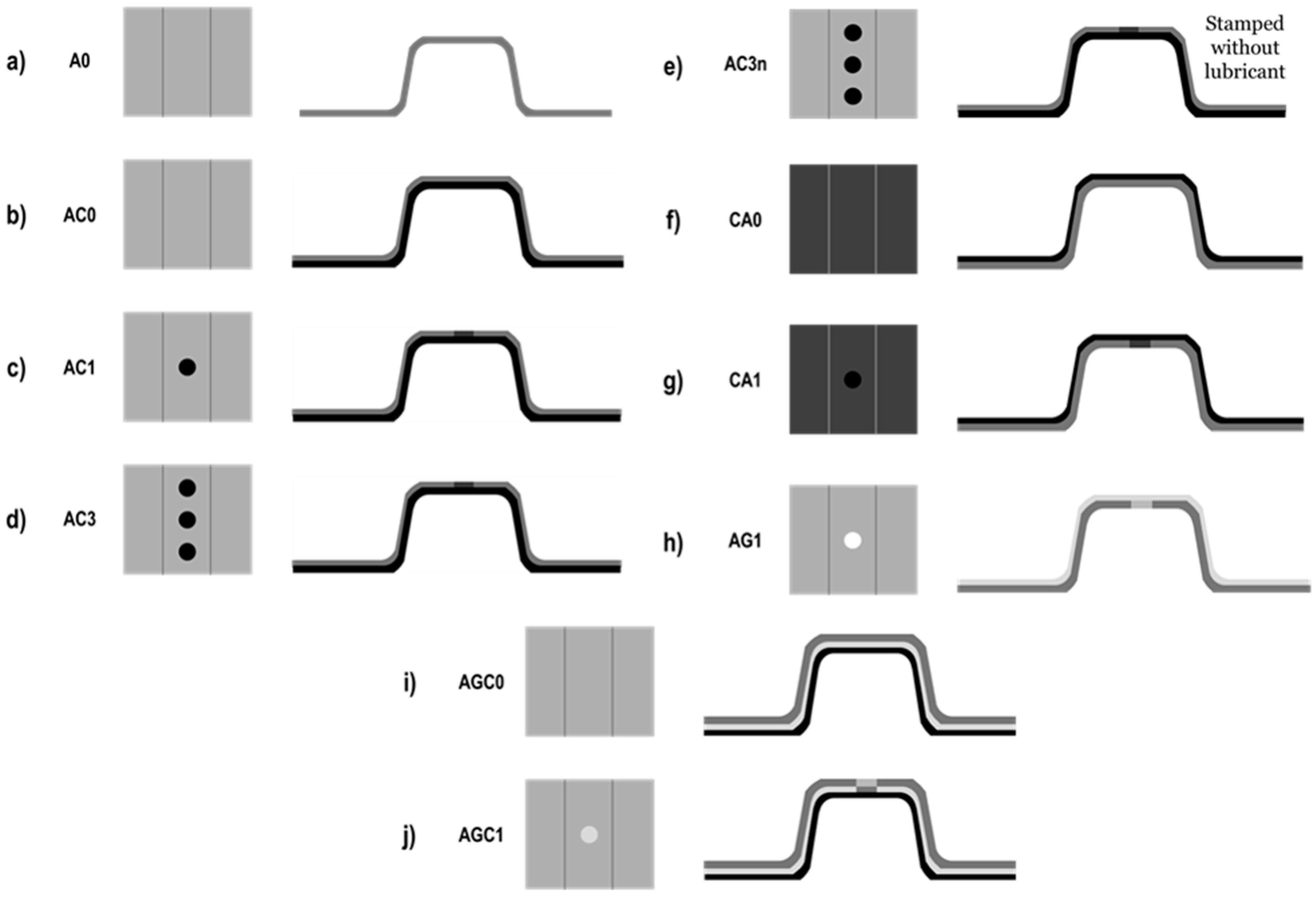
2.2. Specimen Preparation

Specimen processing consisted of three steps: blank preparation, joining by punching, and the stamping of omega parts (Figure 1). Different types of specimens were manufactured considering the variables described in Figure 2 (material lay-up, location of the CFRP reinforcement, lubricant application and number of mechanical joints).
Four specimens of each type were produced, with careful consideration given to the order in which each specimen was stamped, aiming to assess the impact of adhesive friction and galling on the stamped specimens of the same type.

2.2.1. Blank Preparation

Blanks measuring 125 mm × 250 mm were cut from the aluminium sheet. The blanks were thoroughly cleaned with acetone to remove any surface contamination and the uncured prepreg layers were placed on the blanks, except for the reference specimens, which only consisted of aluminium. To prevent the prepreg from adhering to the punch, a silicone paper was placed on top of the composite prepregs.

2.2.2. Joining by Punching

Some of the specimens featured a mechanical joint performed by punching, as detailed in previous work [9]. In this study, the joining process was performed with a punching tooling mounted on a universal testing machine equipped with a 50 kN loadcell, employing a constant punching speed of 10 mm/min, a 10 mm diameter punch (dp) and an 11.3 mm die (dd). This setup resulted in a 24% clearance when Al-CFRP specimens were punched, a 29% clearance for the Al-GFRP specimens and a 21% clearance for the Al-GFRP-CFRP specimens.

2.2.3. Stamping of Omega Parts

The flat sheets were cold formed into omega-shaped profiles at 30 Tn using a Hydrogarne 150 Tn press (Figure 3). This hydraulic press is typically used to assess sheet metal formability, and the obtained results can be considered as demonstrations at a pilot plant level. Stamping operations were performed with the specimens still uncured to prevent delamination and tearing of the composite material.
Lubricant application was carried out using a roller on the aluminium side of the specimen prior to stamping. However, in specimens containing mechanical joints, special caution was adopted to leave the central 15 mm width unlubricated to prevent any potential contamination of the composite epoxy by the lubricant. Furthermore, the silicon paper layer was maintained on top of the composite prepreg to avoid the adhering of the epoxy matrix to the stamping tooling and to allow the composite material to slide freely when stamping.

2.2.4. Specimen Curing

In this study, specimens were cured in a vacuum bag inside an oven with vacuum lines (Figure 4). Nonetheless, in an industrial environment, a more automated process could be implemented by precuring in the stamping tooling, followed, if necessary, by post-curing in the automotive paint shop.
Prior to curing, the silicon paper layer placed on the composite’s surface for punching and stamping was removed. Peel ply was carefully pressed against the composite material surface with a spatula to absorb the excess resin and to ease demoulding. Peel ply was also placed on top of the aluminium side. A rubber pad was placed on top of the mechanical joints on the aluminium side of the specimen to avoid the vacuum from pressing the fibres outside of the aluminium hole (Figure 4).
A vacuum of 0.98 bar was applied for 10 min prior to curing to degas the specimens. Subsequently, the specimens were cured at 150 °C for 30 min.

2.3. Geometrical Characterization

The joint diameter was measured with a calliper after stamping in the x-direction and in the y-direction (Figure 1c) to assess potential joint deformation. The thickness of each specimen was measured using a K4R50 digital gauge from Kröeplin.
The flange springback and deformation of the specimens after curing were assessed by measuring the α angle (Figure 3c) using a protractor. The α angle correlates with the flange springback. Additionally, Rf is the bend radius, which has more influence on the α angle (Figure 3c).

2.4. Compression Test

Mechanical performance of the specimens was evaluated through quasi-static axial compression tests as an approach to assess buckling behaviour of crash components, such as automotive crash-boxes. Crash-boxes are usually made with metals, taking advantage of their ability to dissipate energy through progressive plastic deformation. Their main disadvantage lies in the difficulty of directing the collapse mode. However, composite materials excel in absorbing a higher amount of energy per unit mass compared to metallic structures, dissipating energy through different combined fracture mechanisms (delamination, fibre breakage, fibre debonding and pull-out, and matrix cracking) [25]. Previous literature shows that combining both materials allows higher energy absorption with the high specific strength of composites and metal ductility [26,27]. Moreover, dynamic and static testing of such structures lead to similar collapse modes and differ in the energy absorption capability, which is higher in dynamic testing because of the strain rate effect [28].
Coupons were loaded in compression with displacement control at a 5 mm/min rate. Three specimens of each type were tested with an Instron 5585H with a 250 kN loadcell (Figure 5). Load-displacement curves were registered during testing, and the maximum compression load was extracted and compared among the specimens. True stain was measured by the DIC technique as a qualitative way to assess the buckling behaviour of each type of specimen. DIC measurements were performed on the outer side of the omega profile. Therefore, this side of the specimens was spray painted in white with a black speckle pattern.

3. Results

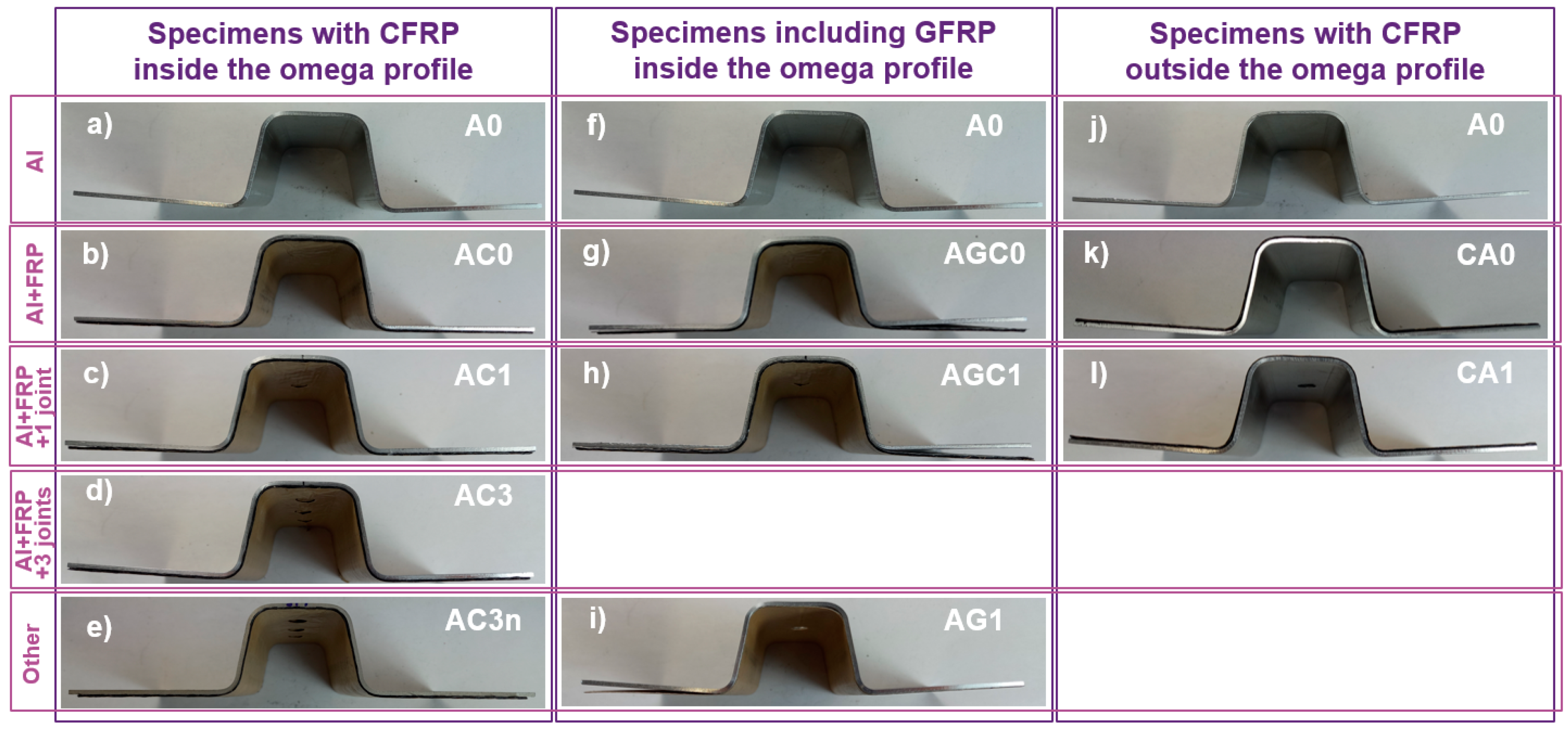
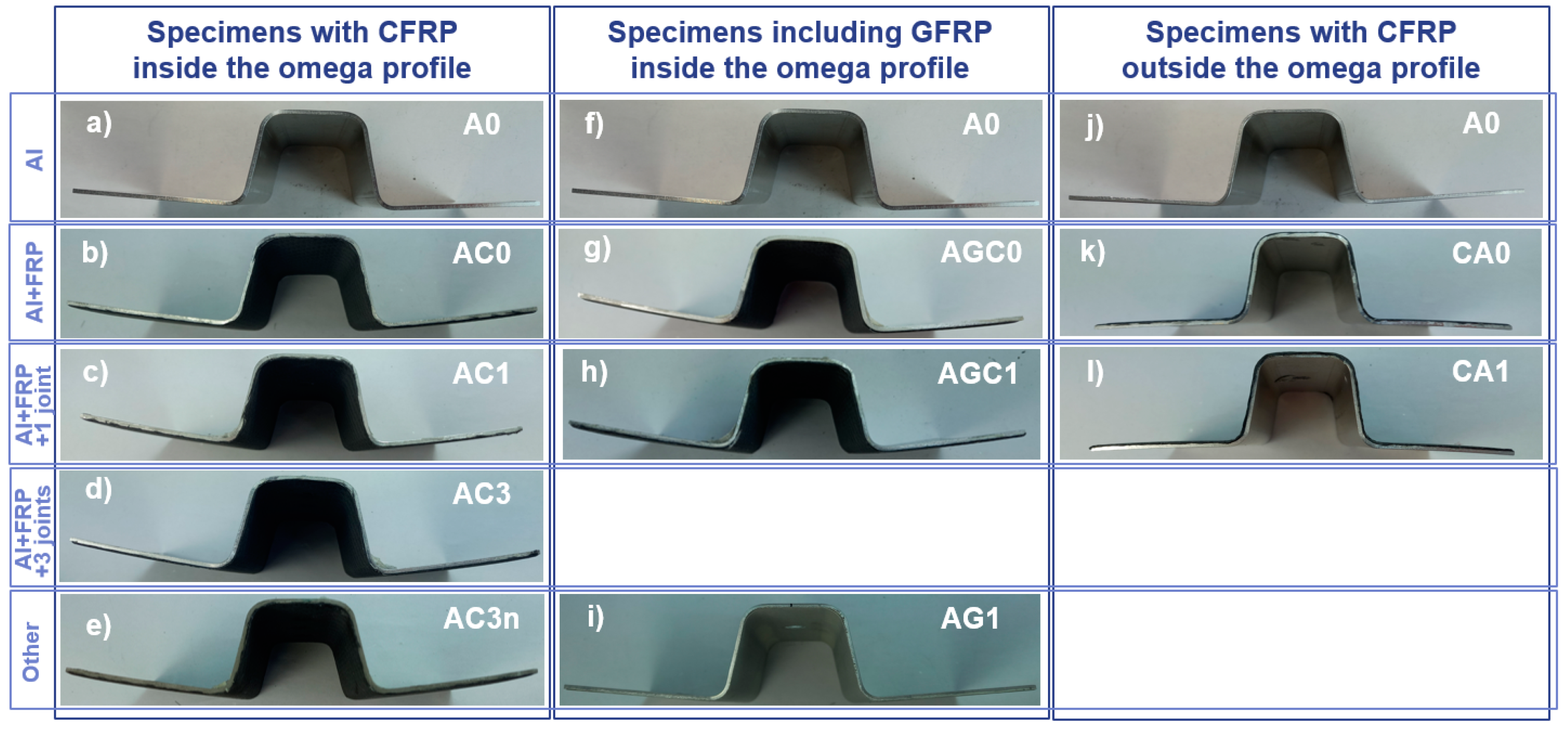
3.1. Multi-Material Forming of Omega Profiles

All specimens were successfully formed into omega-shaped profiles, regardless of the material lay-up and joining configuration. However, aluminium and CFRP specimens with three mechanical joints stamped without using lubricant (AC3n) experienced severe necking and edge cracking after the second stamp, with this phenomenon becoming more severe with each subsequent stamping (Figure 6a). These defects were not present in analogous specimens stamped without lubricant (Figure 6b).
In addition, it was not possible to perform the joint in specimens that incorporated GFRP without a CFRP backup layer (AG1). In these specimens, both the aluminium and CFRP were completely perforated, and no mechanical interlocking is developed at the punched hole.
Analysis of the joint diameter for the specimens with three mechanical joints (Figure 6 and Figure 7) showed that the diameter in the y-direction remained constant both when stamping with (AC3) and without lubricant (AC3n) regardless of the number of stamps. Nevertheless, the joint diameter in the x-direction increased significantly with each successive stamping for specimens stamped without lubricant (Figure 6a and Figure 7a), indicating high plastic deformation in the aluminium sheet in this direction. In this case, only the first AC3n specimen that was stamped had the same diameter in the x- and y- directions. Conversely, the joint diameter in the x-direction of specimens stamped with lubricant remained constant and equal to the diameter in the y-direction, irrespective of the number of stamps.
Visual inspection of the side of the specimens after stamping and prior to curing (Figure 8), together with α angle measurements (Figure 9), showed that specimens without CFRP (A0 and AG1) exhibited large geometry distortion due to springback (Figure 8a,i). This distortion is maintained in specimens featuring CFRP on the outer part of the omega profile (Figure 8j,k). All the aforementioned specimens exhibit a 3° α angle. Yet, there is a notable reduction in the springback effect upon the addition of a CFRP layer on the inner side of the aluminium profile (AC0, AC1, AC3, AC3n, Figure 8b–e). This decrease in springback is also seen in specimens that incorporate a GFRP layer in between the aluminium and the CFRP (AGC0 and AGC1, Figure 8g,h and Figure 7b). Furthermore, Figure 7a shows an increase in the α angle with an increasing number of joints (αAC0 < αAC1 < αAC3) and that the α angle when stamping specimens with three mechanical joints without lubricant (AC3n) was the same as when no joint was applied (AC0).
Post-curing side images (Figure 10) and α angle measurements (Figure 11) revealed significant changes in the flange geometry throughout the curing process. All the specimens where the CFRP was positioned on the inner side of the omega profile experienced an increase of approximately 7° in the α angle, regardless of the number of joints, the use of lubricant when stamping or the presence of a GFRP layer between the CFRP and the aluminium, leading to final α angles in the range of 7–9°. When only GFRP was placed on the inner side of the profile, the increase in the α angles was 2°. Meanwhile, in specimens where the CFRP was placed on the outer side of the profile, the α angle experienced a decrease of approximately 6°, leading to a final angle of −3°.

3.2. Compression Test

Compression load–displacement curves for each type of specimen are shown in Figure 12. The initial part of the compression curve differed from specimen to specimen. With the addition of the composite layer, the maximum load increased. When mechanical joints were added, the peaks showed a higher maximum compression load with a more abrupt load decay.
When CFRP was added to the inner side of the omega profile (AC0), the maximum compression load increased by 13% (Figure 13) compared to the aluminium profile (A0). In addition, the maximum load increased by 19% vs. the A0 when the developed mechanical joint was added in the profile (AC1), regardless of the number of mechanical joints (AC3). When the three mechanical joint specimens were stamped without lubricant (AC3n), there was only an 11% increase in the compression load; however, it must be considered that the maximum compression load decreased with an increasing stamping number (Figure 14).
The addition of GFRP instead of CFRP on the inner side of the omega-shaped profile with one mechanical joint (AG1) only showed an increase of 3% in the maximum compression load (Figure 13b). However, the addition of a GFRP layer in between the CFRP and the Al (AGC0) increased the maximum compression load by 22%, and the addition of a mechanical joint to the previous condition (AGC1) led to a 37% increase.
When placing the CFRP on the outer side of the omega profile (CA0, Figure 13c), the maximum compression load with respect to the aluminium specimen (A0) increased 27%. However, the addition of a mechanical joint on this configuration (CA1) had no influence on the compression load.
The absorbed energy during the compression test was determined by the integration of the load displacement curve up to a displacement of 5 mm. Specimens A0, AC0, AC1 and AC3 showed absorbed energies around 220 J, with no relevant differences among them (less than 3%, with no clear tendency).
Figure 15 shows the true strain digital image correlation images at the completion of the compression test. Through the test, the aluminium profile deformed plastically and buckled, whereas the CFRP did not. Instead, it detached from the aluminium surface and fractured (Figure 14).
Aluminium specimens (A0, Figure 15a) and specimens with aluminium and GFRP (AG1, Figure 15b) experienced asymmetric buckling, which led to global bending of the structure. However, the specimens that incorporated CFRP (the rest of the specimens) experienced symmetric buckling, changing the failure of the structure from global bending to axial folding.
When CFRP was added on the inner part of the omega, the aluminium folding took place towards the outer side (AC0, AC1, AC3, AC3n, AGC0 and AGC1, Figure 16), while when CFRP was added on the outer side, the aluminium folding took place towards the inner side of the omega geometry (CA0 and CA1, Figure 16).
Moreover, when a mechanical joint was added to the specimens with the CFRP on the inner side of the profile (AC1, Figure 15c), the buckling of the specimen was localized in the joint, while when three mechanical joints were added, buckling was localized between the two closest joints (AC1, Figure 15d). However, when lubricant was not applied during stamping, this localization of the buckling was lost after the third specimen stamping.

4. Discussion

Experimental results conducted at a pilot-plant scale demonstrate the viability of cold stamping aluminium with an uncured layer of CFRP prepreg into a complex omega-shaped profile, even when mechanical joints are added to the profile.
The use of lubricant was found crucial for the forming process, since specimens with mechanical joints stamped without lubricant (AC3n, Figure 6a) experienced scratches, necking and edge fracture after the second stamping operation. The severity of these defects increased with each subsequent forming operation, since they were induced by pronounced galling at the tooling. This phenomenon involves the transfer of aluminium from the stamped part to the tooling surface, followed by its hardening through oxidation, work hardening or grain refinement [19]. This hardening leads to a sudden rise in frictional force attributed to microscopic welding [30]. As a result, the aluminium hole of the joint became wider in the direction of sheet deformation (x-direction) and necking appeared in the perpendicular direction (y-direction) due to the large amount of strain localized in the narrowest section of the geometry, resulting in eventual edge cracking. Application of lubricant (AC3, Figure 6b) reduced friction and delayed galling [22], allowing the stamping of specimens with mechanical joints into complex shapes without necking or edge cracking.
It is relevant to mention that in specimens with only aluminium and GFRP (AG1), the mechanical joint could not be performed, since both the aluminium and the GFRP were completely perforated when punching due to the lower strength and stiffness of the glass fibres with respect to the carbon ones. As described in previous work, the mechanical interlocking is only effective for some level or partial punching of the CFRP layer [9]. However, the joint could be performed in specimens that incorporated a CFRP layer beneath the GFRP layer (AGC1).
In terms of springback behaviour, the incorporation of an uncured CFRP prepreg layer in the inner side of the omega profile (AC0, AC1, Ac3, Ac3n, Figure 8 and Figure 9) reduced springback compared to when stamping the aluminium profile without any CFRP layer. Nevertheless, when the CFRP prepreg was incorporated on the outer side of the omega profile (CA0 and CA1, Figure 8 and Figure 9), springback appeared to be similar to when stamping only aluminium sheets. When placing the CFRP prepreg on the inner side of the omega profile, the carbon fibres, which are adhered to the aluminium surface due to the tackiness of the uncured epoxy matrix, appear to be in tension in the radius Rf (Figure 3c). Therefore, the CFRP prepreg restricts the elastic recovery of the aluminium after stamping in this inner position of the omega profile, reducing the springback effects. Nonetheless, when placing the CFRP prepreg on the outer side, the carbon fibres in the Rf radius are compressed and elastic recovery of the aluminium is not restricted. Therefore, springback behaviour is maintained.
The number of mechanical joints also impacted the springback behaviour of the specimens, since the higher number of mechanical joints led to higher springback (Figure 9). This effect was attributed to the relative freedom of movement of the CFRP prepreg in each mechanical joint, generating less restriction to aluminium elastic recovery and resulting in a larger springback.
The curing process also induced changes in the specimen geometry due to the thermal stresses generated by the mismatch in the coefficient of thermal expansion between the carbon fibre and the aluminium. This causes the geometry to bend towards the aluminium side. Therefore, the α angle is increased when the CFRP is placed on the inner side of the profile, and reduced when it is placed on the outer side, even reaching negative values (Figure 10). This phenomenon generated a change in the flange geometry (Figure 8 and Figure 9), which can lead to changes in the compression performance of the specimens.
Regarding the compression performance, reference aluminium specimens (A0, Figure 15a) experienced asymmetric buckling under compression, which led to failure by global bending of the specimen, which is a rapid and undesirable mode of failure. The addition of a GFRP layer on the inner side of the omega profile (AG1, Figure 15f) did not change the failure behaviour of the specimens, leading to only a slight increase in the maximum compression load than the reference.
Nonetheless, the addition of CFRP on the specimen layup changed the crushing behaviour from asymmetric to symmetric (AC0, AC1, AC3, AC3n, CA0, and CA1, Figure 15), regardless of the incorporation of an intermediate GFRP layer (AG0 and AG1). This change in buckling led to an axial folding failure of the specimen, which is far more stable and controlled than the global bending and allowed to reach higher maximum compression loads [25].
The addition of a GFRP layer in between the aluminium and the CFRP (AGC0) further increased the maximum compression load and the absorbed energy. This can be attributed to the higher stiffness of the structure due to the increased cross-section and to the more gradual change of stiffness through the cross-section, which delays the adhesion loss between the different materials.
The change in the CFRP location influenced the folding behaviour of the aluminium sheet. When the CFRP was placed on the omega inner side (AC0, AC1, AC3 and AC3n, Figure 16), the aluminium folding took place towards the outside, regardless of the presence of a GFRP intermediate layer. In contrast, when the CFRP was placed on the omega outer side (CA0 and CA1, Figure 16), aluminium folded towards the inside due to the CFRP constraining outside folding. This restriction of outside folding increased buckling resistance, allowing the structure to bear a higher load before buckling occurs. This was translated into an increase of the maximum compression load when the CFRP was placed on the outer side of the profile. However, since DIC measurements were only taken from the outer side of the profile, folding of the aluminium towards the inside of the profile was not measured with this technique.
Furthermore, the addition of one mechanical joint triggered the buckling at the center of the specimen when CFRP was placed on the inner side of the omega profile (AC1 and AGC1, Figure 15), regardless of the incorporation of an intermediate GFRP layer. This can be explained by geometrical discontinuities favouring axial folding with less bending [31], leading to a more controlled failure and, therefore, higher passenger safety. This localization also led to an increase in the maximum compression load. When three mechanical joints were performed (AC3), buckling was localized between the two closest joints. Despite the buckling localization position being different, the maximum compression load was the same as when only adding one mechanical joint, since axial folding with less bending is also promoted.
However, when the three mechanical joints were stamped without the use of lubricant (AC3n), the localization of the buckling was lost after the 3rd stamp. This was attributed to the severe necking and edge cracking (Figure 6a) caused by the increase in the adhesive friction in each consecutive stamping operation due to galling. This also decreased the maximum compression load with each subsequent stamping (Figure 14b).
Furthermore, the addition of one mechanical joint in the specimens where the CFRP was placed on the outer side of the profile (CA1, Figure 15) did not localize the buckling in the centre of the specimen, and buckled on the edges like specimens without a joint. This was attributed to the fact that compression pressed the CFRP bulge inside the aluminium hole, stiffening the central part of the specimen, which could not buckle. Therefore, no increase in the maximum compression load is seen when adding a mechanical joint to specimens with CFRP on the outer side of the profile (CA1) vs. the same specimen without the mechanical joint (CA0).
Therefore, this work proves the feasibility of joining and forming dissimilar materials with an efficient and fast methodology, which can be easily implemented in the automotive sector. The curing procedure used in this study (vacuum bagging of CFRP prepreg) would not be the choice for high-volume manufacturing. Combining the stamping step with the consolidation of the hybrid structure in a heated tooling (using thermoplastic organosheets or thermoset prepregs) followed by an additional thermal treatment would represent a better integration in the automotive production chain. Additionally, this study proved that that the addition of CFRP layers and interlocking joints allowed for higher control of the buckling behaviour and increased the maximum compression load.

5. Conclusions

Based on the experimental observations made on cold-stamped hybrid panels and on the results of the compression test in the formed omega profile, the following conclusions can be drawn:
  • Multi-material stamping of aluminium with uncured layers of FRP prepregs into complex omega-shaped profiles was as possible, even when mechanical joints through punching were added. Nonetheless, the use of lubricant was crucial for galling prevention, especially in specimens featuring mechanical joints, where galling gave rise to bad-quality parts, showing necking and edge cracking.
  • Springback behaviour was reduced when placing the CFRP in the inner part of the omega profile, since tensile stresses in the carbon fibre restricted the elastic recovery of the aluminium, while this effect was unseen when placing CFRP on the outer side of the profile, where fibres were compressed. Flange geometry was also modified when curing due to thermal stresses induced by the mismatch in the coefficient of thermal expansion between aluminium and CFRP.
  • Quasi-static compression tests showed that the addition of a CFRP layer in the aluminium omega changed the buckling behaviour from asymmetric to symmetric, regardless of the incorporation of a GFRP layer in between both materials, increasing the maximum compression load. When the CFRP was placed on the outer part of the profile, the increase in the compression load was even higher than when it was placed on the inner side, due to higher restriction on the aluminium folding.
  • The incorporation of a mechanical joint through punching on specimens with CFRP on the inner side localized buckling, regardless of the number of joints. This allowed for a higher control of the buckling behaviour, favouring passenger safety, and increased even further the maximum compression load.

Author Contributions

Conceptualization, N.L., D.C. and J.C.; methodology, N.L., E.G.-L. and J.P.; formal analysis, N.L., D.C. and J.C.; investigation, N.L., D.C. and J.C.; resources, D.C.; data curation, N.L.; writing—original draft preparation, N.L.; writing—review and editing, D.C. and J.C.; supervision, D.C. and J.C.; project administration, D.C.; funding acquisition, D.C. All authors have read and agreed to the published version of the manuscript.

Funding

This work was financially supported by the Catalan Government through the funding grant ACCIÓ-Eurecat (Project Flagship-Intelligent).

Data Availability Statement

The raw data supporting the conclusions of this article will be made available by the authors on request.

Acknowledgments

Núria Latorre is a fellow of Eurecat’s “Vicente López predoctoral grant program”. The authors would like to express their gratitude to Anna Payà for her technical assistance with the DIC analysis.

Conflicts of Interest

The authors declare no conflicts of interest. During the preparation of the Introduction section of this work the author(s) used Chat GPT in order to find synonyms and improve grammar. After using this tool/service, the author(s) reviewed and edited the content as needed and take(s) full responsibility for the content of the publication.

Abbreviations

AIaluminium
CFRPCarbon Fibre Reinforced Polymer
DICDigital Image Correlation
GFRPGlass Fibre Reinforced Polymer
RTMResin Transfer Moulding

References

  1. Fleischer, J.; Nieschlag, J. Introduction to CFRP-metal hybrids for lightweight structures. Prod. Eng. 2018, 12, 109–111. [Google Scholar] [CrossRef]
  2. Thoppul, S.D.; Finegan, J.; Gibson, R.F. Mechanics of mechanically fastened joints in polymer–matrix composite structures—A review. Compos. Sci. Technol. 2009, 69, 301–329. [Google Scholar] [CrossRef]
  3. Wang, J.; Zhang, G.; Zheng, X.; Li, J.; Li, X.; Zhu, W.; Yanagimoto, J. A self-piercing riveting method for joining of continuous carbon fiber reinforced composite and aluminum alloy sheets. Compos. Struct. 2021, 259, 113219. [Google Scholar] [CrossRef]
  4. FLambiase, F.; Ko, D.-C. Feasibility of mechanical clinching for joining aluminum AA6082-T6 and Carbon Fiber Reinforced Polymer sheets. Mater. Des. 2016, 107, 341–352. [Google Scholar] [CrossRef]
  5. Caminero, M.; Lopez-Pedrosa, M.; Pinna, C.; Soutis, C. Damage monitoring and analysis of composite laminates with an open hole and adhesively bonded repairs using digital image correlation. Compos. Part B Eng. 2013, 53, 76–91. [Google Scholar] [CrossRef]
  6. Ucsnik, S.; Scheerer, M.; Zaremba, S.; Pahr, D.H. Experimental investigation of a novel hybrid metal–composite joining technology. Compos. Part A Appl. Sci. Manuf. 2010, 41, 369–374. [Google Scholar] [CrossRef]
  7. Graham, D.; Rezai, A.; Baker, D.; Smith, P.; Watts, J. The development and scalability of a high strength, damage tolerant, hybrid joining scheme for composite–metal structures. Compos. Part A Appl. Sci. Manuf. 2014, 64, 11–24. [Google Scholar] [CrossRef]
  8. Galińska, A.; Galiński, C. Mechanical Joining of Fibre Reinforced Polymer Composites to Metals—A Review. Part II: Riveting, Clinching, Non-Adhesive Form-Locked Joints, Pin and Loop Joining. Polymers 2020, 12, 1681. [Google Scholar] [CrossRef]
  9. Latorre, N.; Casellas, D.; Costa, J. A punching process to join metal sheets and fibre reinforced polymer composites by mechanical interlocking. Compos. Part A Appl. Sci. Manuf. 2023, 175, 107744. [Google Scholar] [CrossRef]
  10. Wang, Z.; Lauter, C.; Sanitther, B.; Camberg, A.; Troester, T. Manufacturing and investigation of steel-CFRP hybrid pillar structures for automotive applications by intrinsic resin transfer moulding technology. Int. J. Automot. Compos. 2016, 2, 229. [Google Scholar] [CrossRef]
  11. Taylor, T.; Penney, D.; Yanagimoto, J. One-Step Process for Press Hardened Steel–Carbon Fiber Reinforced Thermoset Polymer Hybrid Parts. Steel Res. Int. 2020, 91, 2000085. [Google Scholar] [CrossRef]
  12. Frantz, M.; Lauter, C.; Tröster, T. Advanced manufacturing technologies for automotive structures in multi-material design consisting of high-strength steels and CFRP. In Proceedings of the 56th International Scientific Colloquium, Ilmenau, Germany, 12–15 September 2011; pp. 12–16. [Google Scholar]
  13. Kim, J.-H.; Jung, Y.-H.; Lambiase, F.; Moon, Y.-H.; Ko, D.-C. Novel Approach toward the Forming Process of CFRP Reinforcement with a Hot Stamped Part by Prepreg Compression Molding. Materials 2022, 15, 4743. [Google Scholar] [CrossRef]
  14. Schmidt, H.C.; Damerow, U.; Lauter, C.; Gorny, B.; Hankeln, F.; Homberg, W.; Troester, T.; Maier, H.J.; Mahnken, R. Manufacturing Processes for Combined Forming of Multi-Material Structures Consisting of Sheet Metal and Local CFRP Reinforcements. Key Eng. Mater. 2012, 504–506, 295–300. [Google Scholar] [CrossRef]
  15. Kondo, K.; Yamashita, Y. US 2015/0298404. 2015. Available online: https://patents.google.com/patent/US20150298404A1/en?oq=US+2015%2f0298404 (accessed on 17 April 2025).
  16. Demes, M.; Janke, N.; Beuscher, J.; Kühn, M.; Dröder, K. Process integration of hot stamping steel and thermoforming fibre-reinforced thermoplastics. Procedia CIRP 2020, 85, 138–143. [Google Scholar] [CrossRef]
  17. Hwang, S.-F.; Li, Y.-R. Deep Drawing Behavior of Metal-Composite Sandwich Plates. Materials 2022, 15, 6612. [Google Scholar] [CrossRef]
  18. Gresham, J.; Cantwell, W.; Cardew-Hall, M.; Compston, P.; Kalyanasundaram, S. Drawing behaviour of metal–composite sandwich structures. Compos. Struct. 2006, 75, 305–312. [Google Scholar] [CrossRef]
  19. Heinrichs, J.; Jacobson, S. The influence from shape and size of tool surface defects on the occurrence of galling in cold forming of aluminium. Wear 2011, 271, 2517–2524. [Google Scholar] [CrossRef]
  20. Lange, K. Handbook of Metal Forming. J. Appl. Met. 1986, 4, 188. [Google Scholar] [CrossRef]
  21. Pujante, J.; Pelcastre, L.; Vilaseca, M.; Casellas, D.; Prakash, B. Investigations into wear and galling mechanism of aluminium alloy-tool steel tribopair at different temperatures. Wear 2013, 308, 193–198. [Google Scholar] [CrossRef]
  22. Heinrichs, J.; Jacobson, S. Laboratory test simulation of aluminium cold forming—Influence from PVD tool coatings on the tendency to galling. Surf. Coat. Technol. 2010, 204, 3606–3613. [Google Scholar] [CrossRef]
  23. Vilaseca, M.; Pujante, J.; Ramírez, G.; Casellas, D. Investigation into adhesive wear of PVD coated and uncoated hot stamping production tools. Wear 2013, 308, 148–154. [Google Scholar] [CrossRef]
  24. Pujante, J.; Vilaseca, M.; Casellas, D.; Riera, M.D. The Role of Adhesive Forces and Mechanical Interaction on Material Transfer in Hot Forming of Aluminium. Tribol. Lett. 2015, 59, 1–8. [Google Scholar] [CrossRef]
  25. Baroutaji, A.; Sajjia, M.; Olabi, A.-G. On the crashworthiness performance of thin-walled energy absorbers: Recent advances and future developments. Thin-Walled Struct. 2017, 118, 137–163. [Google Scholar] [CrossRef]
  26. Hussein, R.D.; Ruan, D.; Lu, G. Cutting and crushing of square aluminium/CFRP tubes. Compos. Struct. 2017, 171, 403–418. [Google Scholar] [CrossRef]
  27. Bambach, M.; Elchalakani, M. Plastic mechanism analysis of steel SHS strengthened with CFRP under large axial deformation. Thin-Walled Struct. 2007, 45, 159–170. [Google Scholar] [CrossRef]
  28. Song, H.-W.; Wan, Z.-M.; Xie, Z.-M.; Du, X.-W. Axial impact behavior and energy absorption efficiency of composite wrapped metal tubes. Int. J. Impact Eng. 2000, 24, 385–401. [Google Scholar] [CrossRef]
  29. Latorre, N.; Casellas, D.; Costa, J.; Garcia-Llamas, E.; Pujante, J. Forming of mechanically interlocked aluminium and carbon fibre reinforced polymer parts with complex geometry. Mater. Res. Proc. 2024, 41, 1640–1649. [Google Scholar] [CrossRef]
  30. Dohda, K.; Yamamoto, M.; Hu, C.; Dubar, L.; Ehmann, K.F. Galling phenomena in metal forming. Friction 2021, 9, 665–685. [Google Scholar] [CrossRef]
  31. Back, P.-E. Deformation Behaviour of an Energy Absorber. Master’s Thesis, Luleå University of Technology, Luleå, Sweden, 2010. [Google Scholar]
Figure 1. Specimen after (a) punching, (b) stamping and (c) curing. Joint deformation is inspected in the x-direction and in the y-direction.
Jcs 09 00204 g001
Figure 2. Description of the specimens investigated in this study. (a) A0: Al sheet, (b) AC0: Al + CFRP, (c) AC1: Al + CFRP with 1 punching joint, (d) AC3: Al + CFRP + 3 joints, (e) AC3n: as case “(d)” without lubricant, (f) CA0: CFRP + Al, (g) CA1: CFRP + Al + 1 joint, (h) AG1: Al + GFRP, (i) AGC0: Al + GFRP + CFRP, (j) AGC1: Al + GFRP + CFRP + 1 joint. Lubricant was applied on the aluminum sheet in contact with the stamping tooling.
Jcs 09 00204 g002
Figure 3. (a) Schematic drawing of the stamping tooling, (b) omega part geometry, and (c) α angle measured to assess specimens’ flange springback. Rf is the omega radius experiencing the highest friction during forming.
Jcs 09 00204 g003
Figure 4. Specimen preparation for curing, (a) Al + CFRP set after stamping; (b) removal of the silicon paper from the CFRP prepreg; (c) rubber pad placed on the aluminium side on top of the mechanical joints to prevent vacuum to suck the fibres through the hole; (d) peel ply placed on the outer and inner surfaces; (e) vacuum bagging.
Jcs 09 00204 g004
Figure 5. Experimental setup for the compression test and test monitoring by means of digital image correlation.
Jcs 09 00204 g005
Figure 6. Stamped aluminium and CFRP specimens with three mechanical joints by stamping order: (a) stamped without lubricant (AC3n) and (b) stamped with lubricant (AC3) [29].
Jcs 09 00204 g006
Figure 7. Joint diameter after stamping in x- and y-direction for specimens with 3 mechanical joints. For specimens AC3n (without lubricant) (a) diameter in x-direction and (b) diameter in y-direction. For specimens AC3 (with lubricant) (c) diameter in x-direction and (d) diameter in y-direction [29].
Jcs 09 00204 g007
Figure 8. Specimen geometry after stamping and before curing. Please, refer to Figure 2 for a description of each specimen shown in the subfigures.
Jcs 09 00204 g008
Figure 9. α angle before curing for springback assessment. Please, refer to Figure 2 for a description of each specimen shown in the subfigures.
Jcs 09 00204 g009
Figure 10. Specimen geometry after curing. Please, refer to Figure 2 for a description of each specimen shown in the subfigures.
Jcs 09 00204 g010
Figure 11. α angle after curing. Please, refer to Figure 2 for a description of each specimen shown in the subfigures.
Jcs 09 00204 g011
Figure 12. Compression load vs. displacement curves. Please, refer to Figure 2 for a description of each specimen shown in the subfigures.
Jcs 09 00204 g012
Figure 13. Maximum compression load per specimen type: (a) specimens with CFRP added on the inner side of the omega profile, (b) specimens with GFRP and CFRP on the inner side of the omega profile and (c) specimens with CFRP on the outer side of the omega profile.
Jcs 09 00204 g013
Figure 14. Maximum compression load obtained for specimens with 3 mechanical joints according to the order in which they were stamped (legend): (a) Specimens stamped with lubricant (AC3) and (b) specimens stamped without lubricant (AC3n).
Jcs 09 00204 g014
Figure 15. Images of compressed omega specimens at 12 mm displacement (when the compression test was stopped). True strain, measured by DIC, is shown. Please, refer to Figure 2 for a description of each specimen shown in the subfigures.
Jcs 09 00204 g015
Figure 16. Omega specimens after compression test. Please, refer to Figure 2 for a description of each specimen shown in the subfigures.
Jcs 09 00204 g016
Disclaimer/Publisher’s Note: The statements, opinions and data contained in all publications are solely those of the individual author(s) and contributor(s) and not of MDPI and/or the editor(s). MDPI and/or the editor(s) disclaim responsibility for any injury to people or property resulting from any ideas, methods, instructions or products referred to in the content.

