
Free Vibration and Buckling Analysis of Functionally Graded Hybrid Reinforced Laminated Composite Plates Under Thermal Conditions


Abstract
1. Introduction
2. Mathematical Formulation
Plate Kinematics
3. Results and Discussion
4. Conclusions
- Higher temperatures reduce both frequency and critical buckling load due to thermal softening;
- Increasing fiber volume fraction (Vf) and graphene platelet weight fraction (Mg) enhances the plate’s stability and vibrational resistance;
- Different FG distributions have varied impacts on the composite’s performance, with FG-X and FG-O showing slightly better structural stability under thermal loads;
- For the FG-X plate, the higher values of Sf and Sg lead to higher critical buckling temperatures, reflecting the reinforcing effect of fiber and graphene platelet distributions;
- For the FG-V and FG-O plates, the higher Sf and Sg values (more dispersed fiber and graphene platelet distributions) reduce the critical buckling temperature, indicating lower thermal stability;
- For the FG-X plate, the higher values of Sf and Sg lead to an increase in fundamental frequency, indicating that concentrated distributions of fibers and graphene platelets improve the vibrational performance of the plate;
- For the FG-V and FG-O plates, the higher values of Sf and Sg (dispersed distributions of fibers and graphene platelets) result in lower fundamental frequencies, indicating reduced vibrational stability.
Author Contributions
Funding
Data Availability Statement
Conflicts of Interest
References
- Beber, V.C.; Fernandes, P.H.E.; Nagel, C.; Arnaut, K. Integrated Analytical and Finite Element-Based Modelling, Manufacturing, and Characterisation of Vacuum-Infused Thermoplastic Composite Laminates Cured at Room Temperature. J. Compos. Sci. 2024, 8, 545. [Google Scholar] [CrossRef]
- Panico, M.; Cozzolino, E.; Papa, I.; Taha, I.; Lopresto, V. An Investigation of the Mechanical Properties of Flax/Basalt Epoxy Hybrid Composites from a Sustainability Perspective. Polymers 2024, 16, 2839. [Google Scholar] [CrossRef] [PubMed]
- Tripathi, K.; Hamza, M.H.; Morales, M.A.; Henry, T.C.; Hall, A.; Chattopadhyay, A. Electromagnetic Interference Shielding Analysis of Hybrid Buckypaper-Reinforced Polymer Matrix Composites: A Quantum Tunneling-Informed Equivalent Circuit Approach. Appl. Sci. 2024, 14, 8960. [Google Scholar] [CrossRef]
- Vargas-Lara, F.; Douglas, J.F. Confronting the Complexity of CNT Materials. Soft Matter 2015, 11, 4888–4898. [Google Scholar] [CrossRef] [PubMed]
- Kardooni, M.R.; Shishesaz, M.; Mosalmani, R. Three-Dimensional Thermo-Mechanical Elastic Analysis of Functionally Graded Five Layers Composite Sandwich Plate on Winkler Foundations. J. Compos. Sci. 2022, 6, 372. [Google Scholar] [CrossRef]
- Liew, K.M.; Lei, Z.X.; Zhang, L.W. Mechanical Analysis of Functionally Graded Carbon Nanotube Reinforced Composites: A Review. Compos. Struct. 2015, 120, 90–97. [Google Scholar] [CrossRef]
- Zhang, H.; Gao, C.; Li, H.; Pang, F.; Zou, T.; Wang, H.; Wang, N. Analysis of Functionally Graded Carbon Nanotubereinforced Composite Structures: A Review. Nanotechnol. Rev. 2020, 9, 1408–1426. [Google Scholar] [CrossRef]
- Soni, S.K.; Thomas, B.; Swain, A.; Roy, T. Functionally Graded Carbon Nanotubes Reinforced Composite Structures: An Extensive Review. Compos. Struct. 2022, 299, 116075. [Google Scholar] [CrossRef]
- Garg, A.; Chalak, H.D.; Belarbi, M.-O.; Zenkour, A.M.; Sahoo, R. Estimation of Carbon Nanotubes and Their Applications as Reinforcing Composite Materials–an Engineering Review. Compos. Struct. 2021, 272, 114234. [Google Scholar] [CrossRef]
- Khalid, S.; Yazdani, M.H.; Azad, M.M.; Elahi, M.U.; Raouf, I.; Kim, H.S. Advancements in Physics-Informed Neural Networks for Laminated Composites: A Comprehensive Review. Mathematics 2024, 13, 17. [Google Scholar] [CrossRef]
- Garg, A.; Chalak, H.D.; Zenkour, A.M.; Belarbi, M.-O.; Houari, M.-S.-A. A Review of Available Theories and Methodologies for the Analysis of Nano Isotropic, Nano Functionally Graded, and CNT Reinforced Nanocomposite Structures. Arch. Comput. Methods Eng. 2022, 29, 2237–2270. [Google Scholar] [CrossRef]
- Mandal, A.; Haldar, S.; Ray, C. Dynamic Analysis of Laminated Composite Skew Plates with Cut-Out. Struct. Eng. Mech. 2018, 68, 639–646. [Google Scholar] [CrossRef]
- Bourada, M.; Bouadi, A.; Bousahla, A.A.; Senouci, A.; Bourada, F.; Tounsi, A.; Mahmoud, S. Buckling Behavior of Rectangular Plates under Uniaxial and Biaxial Compression. Struct. Eng. Mech. 2019, 70, 113–123. [Google Scholar] [CrossRef]
- Lu, J.; Yang, Q.; Meng, Z.; Yang, K.; Xu, W.; Chiu, C. Dynamic Analysis of Functionally Graded Porous (FGP) Elliptic Cylindrical Shell Based on Jacobi Polynomials Ritz Method. J. Compos. Sci. 2023, 7, 344. [Google Scholar] [CrossRef]
- Saiah, B.; Bachene, M.; Guemana, M.; Chiker, Y.; Attaf, B. On the Free Vibration Behavior of Nanocomposite Laminated Plates Contained Piece-Wise Functionally Graded Graphene-Reinforced Composite Plies. Eng. Struct. 2022, 253, 113784. [Google Scholar] [CrossRef]
- Wang, A.; Zhang, K. Free Vibration of Graphene Nanoplatelet-Reinforced Porous Double-Curved Shells of Revolution with a General Radius of Curvature Based on a Semi-Analytical Method. Mathematics 2024, 12, 3060. [Google Scholar] [CrossRef]
- Gao, C.; Zheng, J.; Pang, F.; Xu, J.; Li, H.; Yan, J. Prediction of Time Domain Vibro-Acoustic Response of Conical Shells Using Jacobi–Ritz Boundary Element Method. Acoustics 2024, 6, 523–540. [Google Scholar] [CrossRef]
- Gwak, Y.; Nguyen, S.-N.; Kim, J.-S.; Park, H.; Lee, J.; Han, J.-W. Improved Finite Element Thermomechanical Analysis of Laminated Composite and Sandwich Plates Using the New Enhanced First-Order Shear Deformation Theory. Mathematics 2024, 12, 963. [Google Scholar] [CrossRef]
- Liu, Z.; Tornabene, F.; Dimitri, R.; Babaei, M. Numerical Study of the Buckling Response of Stiffened FG Graphene-Reinforced Multilayer Composite Cylindrical Panels. Processes 2024, 12, 430. [Google Scholar] [CrossRef]
- Saood, A.; Khan, Z.A.; Parvez, M.T.; Khan, A.H. On the Large Amplitude Forced Vibration Analysis of Composite Sectorial Plates. J. Compos. Sci. 2021, 5, 83. [Google Scholar] [CrossRef]
- Thomas, B.; Roy, T. Vibration and Damping Analysis of Functionally Graded Carbon Nanotubes Reinforced Hybrid Composite Shell Structures. J. Vib. Control 2017, 23, 1711–1738. [Google Scholar] [CrossRef]
- Pai, P.F. A New Look at Shear Correction Factors and Warping Functions of Anisotropic Laminates. Int. J. Solids Struct. 1995, 32, 2295–2313. [Google Scholar] [CrossRef]
- Fan, Y.; Wang, H. Nonlinear Dynamics of Matrix-Cracked Hybrid Laminated Plates Containing Carbon Nanotube-Reinforced Composite Layers Resting on Elastic Foundations. Nonlinear Dyn. 2016, 84, 1181–1199. [Google Scholar] [CrossRef]
- Fan, Y.; Wang, H. Nonlinear Bending and Postbuckling Analysis of Matrix Cracked Hybrid Laminated Plates Containing Carbon Nanotube Reinforced Composite Layers in Thermal Environments. Compos. Part B Eng. 2016, 86, 1–16. [Google Scholar] [CrossRef]
- Shen, H.-S.; Xiang, Y.; Lin, F.; Hui, D. Buckling and Postbuckling of Functionally Graded Graphene-Reinforced Composite Laminated Plates in Thermal Environments. Compos. Part B Eng. 2017, 119, 67–78. [Google Scholar] [CrossRef]
- Belkacem, A.; Tahar, H.D.; Abderrezak, R.; Amine, B.M.; Mohamed, Z.; Boussad, A. Mechanical Buckling Analysis of Hybrid Laminated Composite Plates under Different Boundary Conditions. Struct. Eng. Mech. 2018, 66, 761–769. [Google Scholar] [CrossRef]
- Wang, H.; Chen, C.-S.; Hsu, C.-Y.; Chen, W.-R. Vibration and Stability of Initially Stressed Functionally Graded Carbon Nanotube-Reinforced Hybrid Composite Plates in Thermal Environments. Mech. Based Des. Struct. Mach. 2022, 50, 1298–1313. [Google Scholar] [CrossRef]
- Jafari, P.; Kiani, Y. Free Vibration of Functionally Graded Graphene Platelet Reinforced Plates: A Quasi 3D Shear and Normal Deformable Plate Model. Compos. Struct. 2021, 275, 114409. [Google Scholar] [CrossRef]
- Chen, C.-S.; Wang, H.; Chen, T.-J.; Chen, W.-R. Parametric Instability of Functionally Graded Carbon Nanotube-Reinforced Hybrid Composite Plates in Thermal Environments. Int. J. Mech. Mater. Des. 2021, 17, 171–186. [Google Scholar] [CrossRef]
- Garg, A.; Mukhopadhyay, T.; Chalak, H.D.; Belarbi, M.-O.; Li, L.; Sahoo, R. Multiscale Bending and Free Vibration Analyses of Functionally Graded Graphene Platelet/Fiber Composite Beams. Steel Compos. Struct. 2022, 44, 707–720. [Google Scholar] [CrossRef]
- Belarbi, M.-O.; Salami, S.J.; Garg, A.; Daikh, A.-A.; Houari, M.-S.-A.; Dimitri, R.; Tornabene, F. Mechanical Behavior Analysis of FG-CNT-Reinforced Polymer Composite Beams via a Hyperbolic Shear Deformation Theory. Contin. Mech. Thermodyn. 2023, 35, 497–520. [Google Scholar] [CrossRef]
- Wu, C.-P.; Xu, Z.-R. Strong and Weak Formulations of a Mixed Higher-Order Shear Deformation Theory for the Static Analysis of Functionally Graded Beams under Thermo-Mechanical Loads. J. Compos. Sci. 2020, 4, 158. [Google Scholar] [CrossRef]
- Tornabene, F.; Bacciocchi, M. Effect of Curvilinear Reinforcing Fibers on the Linear Static Behavior of Soft-Core Sandwich Structures. J. Compos. Sci. 2018, 2, 14. [Google Scholar] [CrossRef]
- Garg, A.; Chalak, H.D. A Review on Analysis of Laminated Composite and Sandwich Structures under Hygrothermal Conditions. Thin-Walled Struct. 2019, 142, 205–226. [Google Scholar] [CrossRef]
- Chen, C.-S.; Fung, C.-P.; Yang, J.-G. Assessment of Plate Theories for Initially Stressed Hybrid Laminated Plates. Compos. Struct. 2009, 88, 195–201. [Google Scholar] [CrossRef]
- Li, Y.; Liao, Y.; Xie, Z.; Peng, L. Stability Analysis of Curved Beams Based on First-Order Shear Deformation Theory and Moving Least-Squares Approximation. Buildings 2024, 14, 3887. [Google Scholar] [CrossRef]
- Garg, A.; Chalak, H.D.; Zenkour, A.M.; Belarbi, M.-O.; Sahoo, R. Bending and Free Vibration Analysis of Symmetric and Unsymmetric Functionally Graded CNT Reinforced Sandwich Beams Containing Softcore. Thin-Walled Struct. 2022, 170, 108626. [Google Scholar] [CrossRef]
- Chiker, Y.; Bachene, M.; Bouaziz, S.; Guemana, M.; Ben Amar, M.; Haddar, M. Free Vibration Analysis of Hybrid Laminated Plates Containing Multilayer Functionally Graded Carbon Nanotube-Reinforced Composite Plies Using a Layer-Wise Formulation. Arch. Appl. Mech. 2021, 91, 463–485. [Google Scholar] [CrossRef]
- Chalak, H.D.; Zenkour, A.M.; Garg, A. Free Vibration and Modal Stress Analysis of FG-CNTRC Beams under Hygrothermal Conditions Using Zigzag Theory. Mech. Based Des. Struct. Mach. 2021, 51, 4709–4730. [Google Scholar] [CrossRef]
- Dat, N.D.; Quan, T.Q.; Mahesh, V.; Duc, N.D. Analytical Solutions for Nonlinear Magneto-Electro-Elastic Vibration of Smart Sandwich Plate with Carbon Nanotube Reinforced Nanocomposite Core in Hygrothermal Environment. Int. J. Mech. Sci. 2020, 186, 105906. [Google Scholar] [CrossRef]
- Garg, A.; Belarbi, M.O.; Chalak, H.D.; Li, L.; Sharma, A.; Avcar, M.; Sharma, N.; Paruthi, S.; Gulia, R. Buckling and Free Vibration Analysis of Bio-Inspired Laminated Sandwich Plates with Helicoidal/Bouligand Face Sheets Containing Softcore. Ocean Eng. 2023, 270, 113684. [Google Scholar] [CrossRef]
- Lei, Z.X.; Liew, K.M.; Yu, J.L. Free Vibration Analysis of Functionally Graded Carbon Nanotube-Reinforced Composite Plates Using the Element-Free Kp-Ritz Method in Thermal Environment. Compos. Struct. 2013, 106, 128–138. [Google Scholar] [CrossRef]
- Zhu, P.; Lei, Z.X.; Liew, K.M. Static and Free Vibration Analyses of Carbon Nanotube-Reinforced Composite Plates Using Finite Element Method with First Order Shear Deformation Plate Theory. Compos. Struct. 2012, 94, 1450–1460. [Google Scholar] [CrossRef]

 0,
0,  0.1,
0.1,  0.2,
0.2,  0.3,
0.3,  0.4, and
  0.5 at (a) 300 K, (b) 325 K, (c) 350 K, (d) 375 K, and (e) 400 K with and .
0, 0.1, 0.2, 0.3, 0.4, and 0.5 at (a) 300 K, (b) 325 K, (c) 350 K, (d) 375 K, and (e) 400 K with and .
0.5 at (a) 300 K, (b) 325 K, (c) 350 K, (d) 375 K, and (e) 400 K with and .
0, 0.1, 0.2, 0.3, 0.4, and 0.5 at (a) 300 K, (b) 325 K, (c) 350 K, (d) 375 K, and (e) 400 K with and . 0, 0.1, 0.2, 0.3, 0.4, and 0.5 at (a) 300 K, (b) 325 K, (c) 350 K, (d) 375 K, and (e) 400 K with and .
0, 0.1, 0.2, 0.3, 0.4, and 0.5 at (a) 300 K, (b) 325 K, (c) 350 K, (d) 375 K, and (e) 400 K with and .
0, 0.1, 0.2, 0.3, 0.4, and 0.5 at (a) 300 K, (b) 325 K, (c) 350 K, (d) 375 K, and (e) 400 K with and .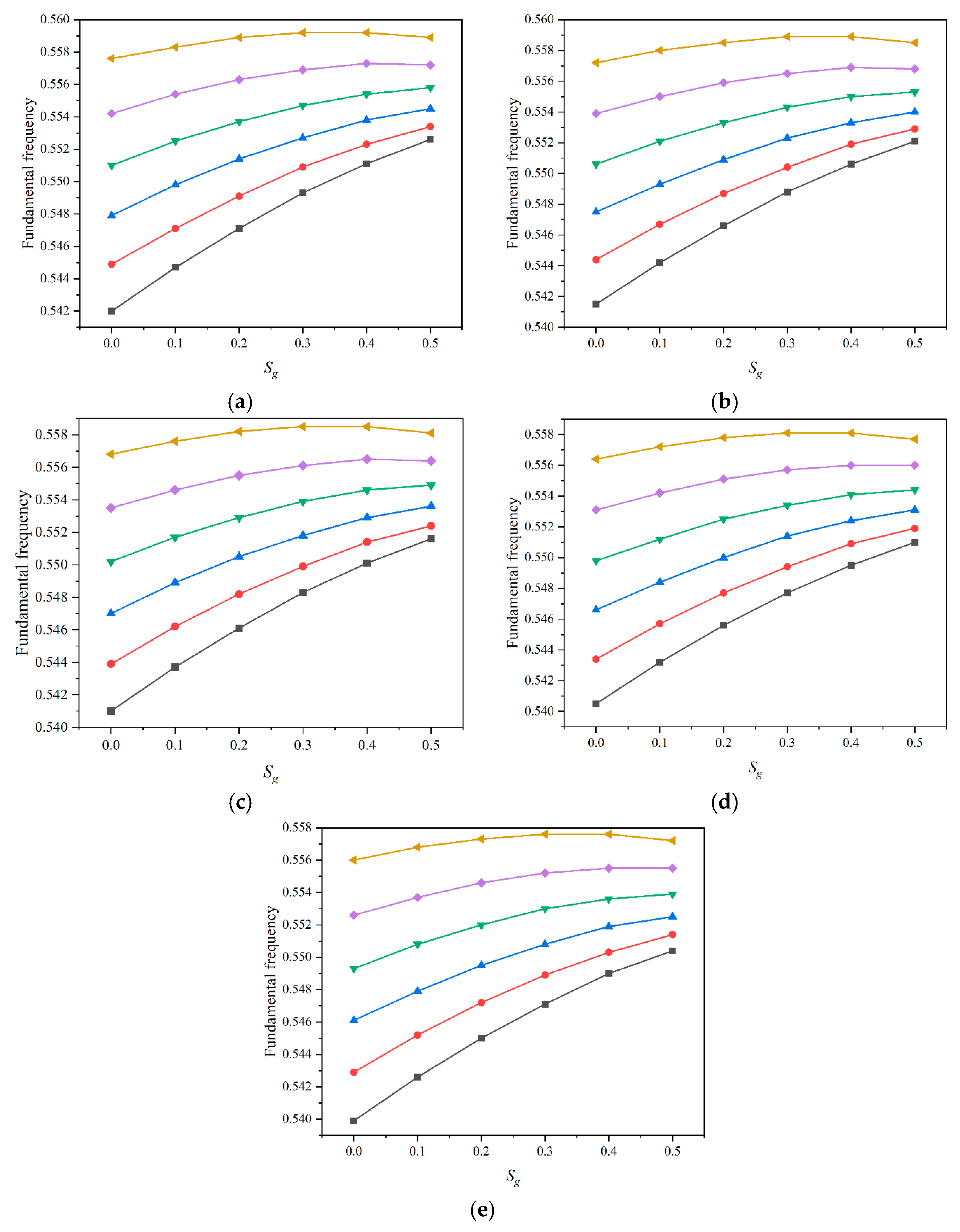 0, 0.1, 0.2, 0.3, 0.4, and 0.5 at (a) 300 K, (b) 325 K, (c) 350 K, (d) 375 K, and (e) 400 K with and .
0, 0.1, 0.2, 0.3, 0.4, and 0.5 at (a) 300 K, (b) 325 K, (c) 350 K, (d) 375 K, and (e) 400 K with and .
0, 0.1, 0.2, 0.3, 0.4, and 0.5 at (a) 300 K, (b) 325 K, (c) 350 K, (d) 375 K, and (e) 400 K with and .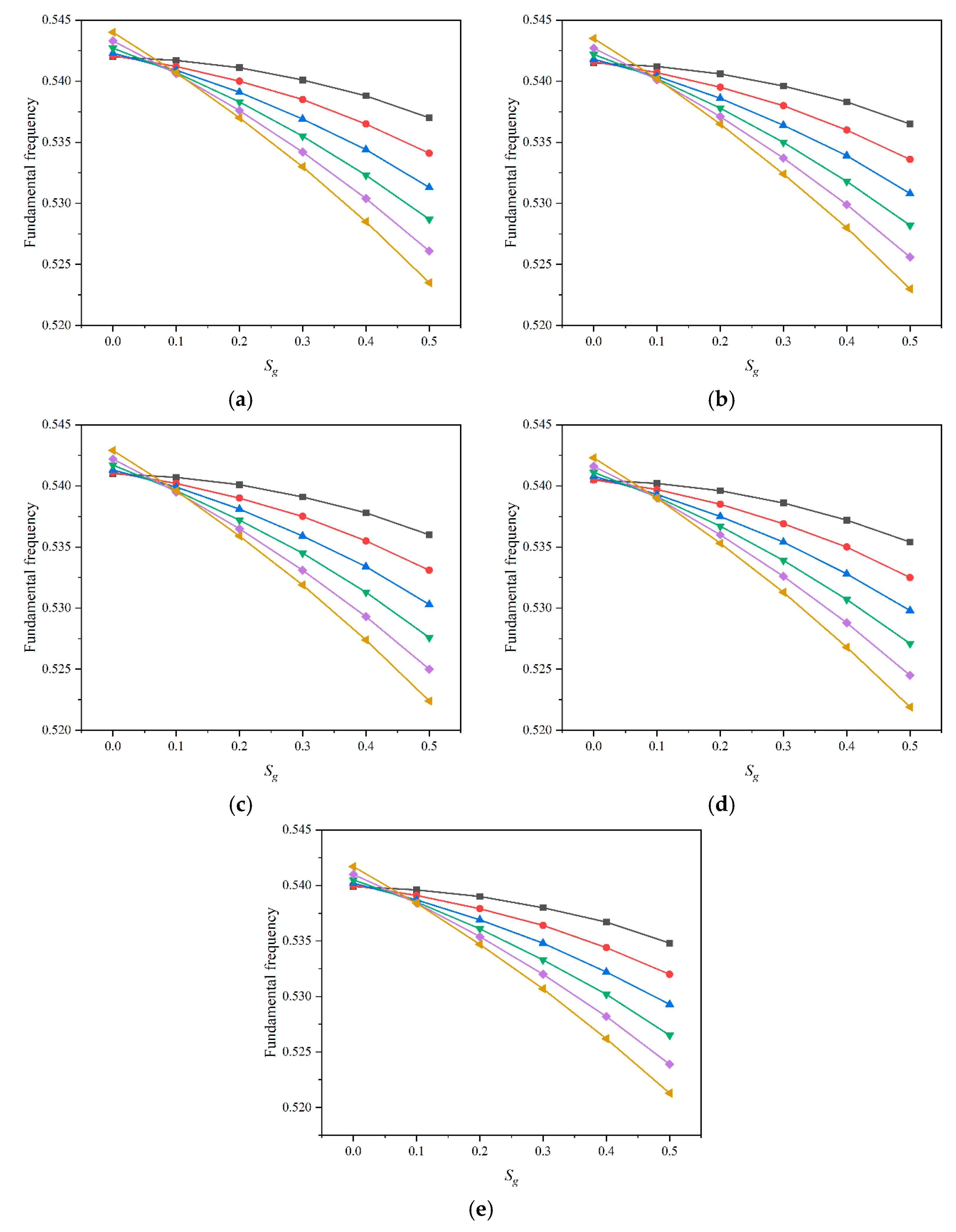 0, 0.1, 0.2, 0.3, 0.4, and 0.5 at (a) 300 K, (b) 325 K, (c) 350 K, (d) 375 K, and (e) 400 K with and .
0, 0.1, 0.2, 0.3, 0.4, and 0.5 at (a) 300 K, (b) 325 K, (c) 350 K, (d) 375 K, and (e) 400 K with and .
0, 0.1, 0.2, 0.3, 0.4, and 0.5 at (a) 300 K, (b) 325 K, (c) 350 K, (d) 375 K, and (e) 400 K with and .

| Source | FG-X | FG-U | FG-V | FG-O |
|---|---|---|---|---|
| Present | 14.897 | 13.650 | 12.781 | 11.691 |
| Lei et al. [42] | 14.578 | 13.495 | 12.416 | 11.514 |
| Zhu et al. [43] | 14.616 | 13.532 | 12.452 | 11.550 |
| FG-X | FG-U | FG-V | FG-O | |||||||
|---|---|---|---|---|---|---|---|---|---|---|
| B * | F | B | F | B | F | B | F | |||
| 300 | 0.01 | 0.10 | 0.7382 | 0.3306 | 0.6164 | 0.3037 | 0.6371 | 0.3000 | 0.4876 | 0.2679 |
| 0.25 | 0.7780 | 0.3922 | 0.6454 | 0.3632 | 0.6700 | 0.3583 | 0.5202 | 0.3200 | ||
| 0.50 | 1.0344 | 0.4717 | 0.8322 | 0.4427 | 0.8584 | 0.4360 | 0.7092 | 0.3905 | ||
| 0.02 | 0.10 | 0.7926 | 0.4096 | 0.6602 | 0.3773 | 0.6738 | 0.3702 | 0.5209 | 0.3311 | |
| 0.25 | 0.8467 | 0.4511 | 0.7085 | 0.4213 | 0.7145 | 0.4112 | 0.5755 | 0.3712 | ||
| 0.50 | 1.1086 | 0.5101 | 0.9073 | 0.4834 | 0.9004 | 0.4698 | 0.7806 | 0.4281 | ||
| 0.05 | 0.10 | 0.8392 | 0.5606 | 0.7129 | 0.5254 | 0.7075 | 0.5090 | 0.5759 | 0.4632 | |
| 0.25 | 0.8939 | 0.5488 | 0.7817 | 0.5270 | 0.7560 | 0.5072 | 0.6671 | 0.4735 | ||
| 0.50 | 1.1440 | 0.5589 | 0.9901 | 0.5420 | 0.9468 | 0.5235 | 0.8965 | 0.4952 | ||
| 325 | 0.01 | 0.10 | 0.6809 | 0.3294 | 0.5682 | 0.3025 | 0.5876 | 0.2988 | 0.4490 | 0.2667 |
| 0.25 | 0.7169 | 0.3912 | 0.5947 | 0.3622 | 0.6177 | 0.3573 | 0.4789 | 0.3190 | ||
| 0.50 | 0.9530 | 0.4708 | 0.7669 | 0.4420 | 0.7916 | 0.4353 | 0.6532 | 0.3897 | ||
| 0.02 | 0.10 | 0.7315 | 0.4083 | 0.6090 | 0.3760 | 0.6218 | 0.3689 | 0.4800 | 0.3298 | |
| 0.25 | 0.7812 | 0.4502 | 0.6534 | 0.4204 | 0.6592 | 0.4103 | 0.5302 | 0.3701 | ||
| 0.50 | 1.0228 | 0.5096 | 0.8367 | 0.4828 | 0.8308 | 0.4692 | 0.7194 | 0.4274 | ||
| 0.05 | 0.10 | 0.7749 | 0.5592 | 0.6579 | 0.5240 | 0.6532 | 0.5076 | 0.5311 | 0.4617 | |
| 0.25 | 0.8254 | 0.5480 | 0.7214 | 0.5260 | 0.6978 | 0.5063 | 0.6151 | 0.4724 | ||
| 0.50 | 1.0564 | 0.5585 | 0.9137 | 0.5415 | 0.8739 | 0.5230 | 0.8267 | 0.4946 | ||
| 350 | 0.01 | 0.10 | 0.6317 | 0.3282 | 0.5269 | 0.3012 | 0.5452 | 0.2976 | 0.4158 | 0.2654 |
| 0.25 | 0.6646 | 0.3901 | 0.5511 | 0.3612 | 0.5729 | 0.3563 | 0.4435 | 0.3179 | ||
| 0.50 | 0.8832 | 0.4699 | 0.7108 | 0.4412 | 0.7342 | 0.4346 | 0.6052 | 0.3889 | ||
| 0.02 | 0.10 | 0.6791 | 0.4070 | 0.5650 | 0.3747 | 0.5772 | 0.3676 | 0.4449 | 0.3285 | |
| 0.25 | 0.7250 | 0.4493 | 0.6060 | 0.4193 | 0.6118 | 0.4093 | 0.4913 | 0.3691 | ||
| 0.50 | 0.9493 | 0.5090 | 0.7762 | 0.4822 | 0.7710 | 0.4686 | 0.6669 | 0.4266 | ||
| 0.05 | 0.10 | 0.7199 | 0.5578 | 0.6108 | 0.5225 | 0.6066 | 0.5062 | 0.4927 | 0.4602 | |
| 0.25 | 0.7668 | 0.5471 | 0.6696 | 0.5250 | 0.6480 | 0.5053 | 0.5704 | 0.4712 | ||
| 0.50 | 0.9814 | 0.5581 | 0.8482 | 0.5410 | 0.8113 | 0.5224 | 0.7669 | 0.4938 | ||
| 375 | 0.01 | 0.10 | 0.5890 | 0.3269 | 0.4910 | 0.3000 | 0.5083 | 2.9634 | 0.3870 | 0.2642 |
| 0.25 | 0.6191 | 0.3890 | 0.5134 | 0.3601 | 0.5340 | 0.3553 | 0.4128 | 0.3169 | ||
| 0.50 | 0.8226 | 0.4690 | 0.6621 | 0.4403 | 0.6845 | 0.4338 | 0.5635 | 0.3880 | ||
| 0.02 | 0.10 | 0.6337 | 0.4056 | 0.5270 | 0.3733 | 0.5385 | 0.3663 | 0.4145 | 0.3271 | |
| 0.25 | 0.6762 | 0.4483 | 0.5650 | 0.4183 | 0.5706 | 0.4083 | 0.4576 | 0.3680 | ||
| 0.50 | 0.8855 | 0.5084 | 0.7237 | 0.4815 | 0.7193 | 0.4680 | 0.6213 | 0.4259 | ||
| 0.05 | 0.10 | 0.6721 | 0.5562 | 0.5700 | 0.5209 | 0.5662 | 0.5047 | 0.4594 | 0.4586 | |
| 0.25 | 0.7160 | 0.5461 | 0.6248 | 0.5240 | 0.6047 | 0.5043 | 0.5317 | 0.4700 | ||
| 0.50 | 0.9164 | 0.5577 | 0.7915 | 0.5405 | 0.7571 | 0.5219 | 0.7150 | 0.4931 | ||
| 400 | 0.01 | 0.10 | 0.5516 | 0.3255 | 0.4596 | 0.2986 | 0.4761 | 0.2950 | 0.3618 | 0.2628 |
| 0.25 | 0.5793 | 0.3878 | 0.4803 | 0.3590 | 0.4999 | 0.3543 | 0.3858 | 0.3158 | ||
| 0.50 | 0.7695 | 0.4680 | 0.6194 | 0.4395 | 0.6410 | 0.4330 | 0.5270 | 0.3872 | ||
| 0.02 | 0.10 | 0.5939 | 0.4042 | 0.4936 | 0.3718 | 0.5047 | 0.3648 | 0.3879 | 0.3256 | |
| 0.25 | 0.6336 | 0.4472 | 0.5290 | 0.4172 | 0.5346 | 0.4072 | 0.4281 | 0.3668 | ||
| 0.50 | 0.8297 | 0.5077 | 0.6777 | 0.4808 | 0.6740 | 0.4673 | 0.5814 | 0.4250 | ||
| 0.05 | 0.10 | 0.6304 | 0.5546 | 0.5342 | 0.5192 | 0.5309 | 0.5030 | 0.4302 | 0.4569 | |
| 0.25 | 0.6715 | 0.5452 | 0.5855 | 0.5228 | 0.5669 | 0.5032 | 0.4978 | 0.4687 | ||
| 0.50 | 0.8595 | 0.5572 | 0.7418 | 0.5399 | 0.7097 | 0.5213 | 0.6696 | 0.4923 | ||
Disclaimer/Publisher’s Note: The statements, opinions and data contained in all publications are solely those of the individual author(s) and contributor(s) and not of MDPI and/or the editor(s). MDPI and/or the editor(s) disclaim responsibility for any injury to people or property resulting from any ideas, methods, instructions or products referred to in the content. |
© 2025 by the authors. Licensee MDPI, Basel, Switzerland. This article is an open access article distributed under the terms and conditions of the Creative Commons Attribution (CC BY) license (https://creativecommons.org/licenses/by/4.0/).
Share and Cite
Gulia, R.; Garg, A.; Sahu, V.; Li, L. Free Vibration and Buckling Analysis of Functionally Graded Hybrid Reinforced Laminated Composite Plates Under Thermal Conditions. J. Compos. Sci. 2025, 9, 94. https://doi.org/10.3390/jcs9030094
Gulia R, Garg A, Sahu V, Li L. Free Vibration and Buckling Analysis of Functionally Graded Hybrid Reinforced Laminated Composite Plates Under Thermal Conditions. Journal of Composites Science. 2025; 9(3):94. https://doi.org/10.3390/jcs9030094
Chicago/Turabian StyleGulia, Reeta, Aman Garg, Vaishali Sahu, and Li Li. 2025. "Free Vibration and Buckling Analysis of Functionally Graded Hybrid Reinforced Laminated Composite Plates Under Thermal Conditions" Journal of Composites Science 9, no. 3: 94. https://doi.org/10.3390/jcs9030094
APA StyleGulia, R., Garg, A., Sahu, V., & Li, L. (2025). Free Vibration and Buckling Analysis of Functionally Graded Hybrid Reinforced Laminated Composite Plates Under Thermal Conditions. Journal of Composites Science, 9(3), 94. https://doi.org/10.3390/jcs9030094