Article

Non-Destructive Evaluation of Impact-Damaged Sandwich Composites: Influence of Fiber Type

1
University of Coimbra, CEMMPRE-ARISE, Department of Electrical and Computers Engineering, Polo II, Rua Sílvio Lima, 3030-970 Coimbra, Portugal
2
University of Coimbra, CEMMPRE-ARISE, Department of Mechanical Engineering, Polo II, Rua Luís Reis Santos, 3030-788 Coimbra, Portugal
*
Author to whom correspondence should be addressed.
J. Compos. Sci. 2025, 9(2), 86; https://doi.org/10.3390/jcs9020086
Submission received: 3 January 2025 / Revised: 6 February 2025 / Accepted: 8 February 2025 / Published: 12 February 2025
(This article belongs to the Special Issue Recent Progress in Hybrid Composites)

Abstract

:
This study deals with the evaluation of impact-damaged sandwich composites using different fiber types (carbon, glass, and Kevlar), where the outer layers, or “skins”, were made from the same type of fiber, while the inner layer, or “core”, consisted of a different fiber type, with the aim of improving the damage resistance and tolerance of composite materials. To achieve this goal, the following research question was formulated: can the type of core fiber used in sandwich composites primarily determine their structural response under impact? To obtain a consolidated answer, various configurations manufactured were subjected to low-velocity impact tests to induce damage. The next step involved evaluating the extent and distribution of damage across various samples using ultrasonic C-scan techniques, along with assessing the impact bending stiffness (IBS) property, a widely recognized method for measuring the structural response of composites. It was observed that the different composite configurations presented distinct absorbed energy and, consequently, different damages, which was confirmed by the IBS and the C-scan methods. The glass–carbon–glass (GCG) sandwich composite demonstrated superior performance in mitigating damage compared to the other sandwich designs. The core material was verified as the main factor influencing the response of the sandwich composite.

1. Introduction

The structural stability and high specific strength and stiffness of composite materials, combined with the reduction in structural weight, resulting in fuel savings and im-proved performance compared to traditional materials, justify their great appeal for most industrial applications, such as in the automotive and aerospace industries [1,2,3,4].
Nevertheless, the low transverse strength of composites still limits their applications in many industrial areas due to the lack of reinforcement in that direction and the fact that the mechanical properties are dominated by the matrix and/or fiber/matrix interface. That behavior can provide some weakness with respect to impact damages, in particular low-velocity impacts, which can result from operational and/or maintenance activities. Additionally, such events can give rise to damages that are very difficult to detect by simple visual observation [5,6,7,8], and also promote significant reduction of the residual mechanical properties [9,10,11,12,13,14].
Additionally, the collapse that abruptly occurs in a brittle manner in composites, particularly those using brittle fibers, is also a problem in many applications. To mitigate this problem, without compromising the properties of the composite, it is common to make use of hybridization, which consists of applying two or more types of fibers in the same matrix and adapting them for a very specific design requirement [14,15,16,17]. In this concept, high-modulus and/or low-elongation (LE) fibers provide stiffness and strength, while low-modulus and/or high-elongation (HE) fibers promote greater elongation and damage tolerance. In this context, it is crucial to analyze the influence of different fiber arrangements within laminates in terms of low-velocity impact response. Hung et al. [18], for instance, carried out experimental works involving carbon–glass hybrid laminates, and concluded that damage is minimized when carbon fibers are positioned in the surface layers and glass fibers in their core, while in samples with the opposite arrangement (glass fibers in the surface layer), the observed damage is significantly greater. Chen et al. [19] analyzed the carbon–glass–basalt hybrid effects on the impact response, and they observed that incorporating ductile fibers in the hybridization process resulted in significant improvements in the impact strength. Cheon et al. [20] found that carbon–aramid composites promoted better impact strength than composites involving single carbon fibers and, consequently, the damaged area decreased significantly as well as the breakage of carbon fibers. Zhang et al. [21] studied the low-velocity impact response of intralayer hybrid composite laminates, involving carbon (C) and glass (G) fibers, and found that while the hybridization improved the peak force and absorbed energy, the hybrid ratio and intralayer structure had a major effect on the failure mechanism. For example, C:G = 1:1 laminates showed the best impact strength among the intra-ply hybrid structures, while C:G = 1:4 laminates showed less damage and a smaller delamination area due to their lower carbon fiber content. For both laminates, the carbon fibers are always in the upper part of the composite, which is submitted to impact. Experimental and numerical studies were carried out by Liu et al. [22] to evaluate the damage in composite laminates incorporating unidirectional carbon fibers with carbon fabrics. The authors concluded that whenever the fabrics are positioned on the top and bottom of the laminates, they promote lower damages. Moreover, Tianya et al. [23] compared the impact response of laminates involving only carbon (C), glass (G), and polyethylene (PE) fibers, with carbon–PE and carbon–glass hybrids, concluding that while the C–G configuration improved the toughness of the composite, the C–PE hybridization exhibited greater energy absorption as a result of the ductility of the PE fibers. Based on the studies mentioned, it can be concluded that the fibers can be arranged in different ways to achieve the benefits of hybridization on the impact response.
In this study, the authors employed a sandwich-structured design using different types of fibers. The outer layers, or “skins”, were made from the same type of fiber, while the inner layer, or “core”, consisted of a different fiber type. The objective was to enhance the damage resistance and tolerance of composite materials. To achieve this, carbon, glass, and Kevlar fibers were initially employed in a single-fiber configuration, followed by a sandwich approach. In order to produce damages, low-velocity impact tests were carried out on the composite samples in accordance with the ASTM D 7136 standard [24]. The next step involved assessing the extent and pattern of damage in the various samples, using ultrasonic C-scan techniques. The damage analysis was also complemented by an assessment of impact bending stiffness (IBS), which is a property widely used to evaluate the structural response of composites.
The great novelty of this study is the evaluation of the effect of different fibers, other than the classic ones, in the core of the sandwich composite, in view of the hybridization effect. This study demonstrated this influence and how the fibers affect the structural response of this sandwich composite.

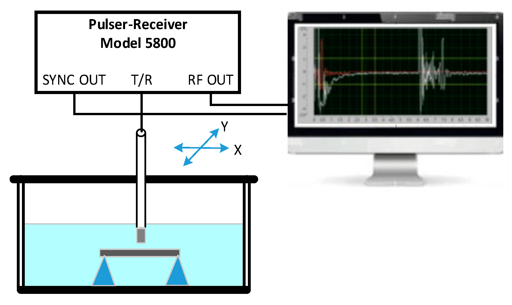
2. Materials and Experimental Procedure

Different composite laminates were produced by hand layup involving carbon-fiber-woven bidirectional fabric (taffeta with 195 g/m2), glass-fiber-woven bidirectional fabric (taffeta with 195 g/m2), and Kevlar-fiber-woven bidirectional fabric (taffeta with 170 g/m2), and an Ebalta AH 150 resin and IP 430 hardener. All bidirectional fabrics were stacked with the fibers in the same direction, and 12 layers were used for all configurations. Composite plates with dimensions of 330 × 330 × t mm3 (where t is the thickness) were produced. In order to guarantee uniform thickness and constant fiber volume fraction, the fiber/resin system was placed inside a vacuum bag, and then, using a hydraulic press, a load of 2.5 kN was applied for 24 h. In the first 2 h, the bag was vacuumed to remove any air bubbles resulting from the manufacturing process, and after 24 h of curing at room temperature, the laminates were subjected to post-curing in an oven at 80 °C for 5 h. More details about the manufacturing process can be found in [25]. Table 1 summarize the configurations analyzed in this study, where the labels identify the number of layers and the fiber type (C—carbon, K—Kevlar, and G—glass). Two different configurations were studied: laminates incorporating only single fibers (carbon, glass, or Kevlar) and laminates in sandwich shape, combining the different fibers. In Table 1, the average thickness of all studied samples is also represented. It should be noted that, according to Monjon et al. [25], due to the good fiber/matrix adhesion that glass and carbon fibers present, the mechanical performance is superior to configurations involving Kevlar fibers due to their weak fiber/matrix adhesion. This justifies that only the 4G–4K–4G configuration is studied.
The impact tests used to produce the damage were carried out in accordance with the ASTM D 7136 standard, at room temperature and on a CEAST 9340 drop weight test machine with an impactor of 10 mm in diameter and mass of 3.4 kg. An impact energy of 12 J was applied to induce damage in the samples, a value that has been carefully studied to prevent perforation, which corresponds to an impact velocity of 2.65 ms−1. This impact energy was obtained in previous studies performed by the authors, in order to achieve the energy capable of introducing damage without perforation. Finally, the impact tests were performed on a circular section with a diameter of 70 mm, with the impactor striking directly at the center. For this purpose, specimens with dimensions of 100 × 100 × t mm3 (see Figure 1) were used, obtained from those plates by a diamond saw and a controlled speed to avoid internal damage and any chemical changes in the matrix due to overheating. Five samples of each configuration shown in Table 1 were tested.
The next step involved assessing the extent and pattern of damage in the various samples. To do this, ultrasonic C-scan techniques, both immersion and air-coupled methods, were employed, to evaluate and compare their effectiveness in inspecting those composites. The images obtained by the immersion C-scan approach were produced using a pulse–echo configuration with a single 5 MHz probe and active diameter of 6.35 mm, unfocused (Olympus), and excited by a pulser–receiver model 5800 from Panametrics, as illustrated in Figure 2. The air-coupling C-scan makes use of two 400 kHz focalized probes working in through-transmission mode (one as transmitter and the other as receiver), as shown in Figure 3.
The damage analysis was also complemented by an assessment of impact bending stiffness (IBS), which is a property widely used to evaluate the structural response of composites subjected to low-velocity impacts. According to David-West et al. [26,27], IBS is an important property to consider when assessing the damage resistance of composites, and can be obtained by the slope of the ascending section of the load–displacement curve.

3. Results and Discussion

3.1. Impact Characterization

Figure 4 illustrates the typical energy-versus-time curves for the composites consisting solely of single fibers (C, K, G). Figure 5 represents the load-versus-displacement curves for the referred composites. It should be noted that the illustrated curves are representative of all the others and agree with those described in the literature [28,29,30].
Figure 4 shows the existence of a plateau after the maximum energy (12 J), which means that the impactor no longer contacts the sample. In this context, the difference between the value of the maximum energy and the energy defined by the plateau is called the elastic energy and, consequently, the difference between the elastic energy and the maximum energy represents the absorbed energy.
On the other hand, Figure 5 shows that, regardless of the composite material, the load increases until it reaches a peak value. After that maximum value, the load decreases, and beyond a certain displacement, the drop becomes quite steep, due to the impactor losing contact with the sample. Additionally, key parameters that characterize the impact response of the composites with single fibers can be extracted from Figure 4 and Figure 5, such as average and standard deviation values of the maximum load and displacement as well as elastic energy. They are represented in Table 2.
The results show that for the energy level used, carbon and glass laminates have very similar maximum impact load (2276 and 2372 N) and maximum displacement values (7.5 and 7.6 mm), although the elastic energy (7% and 16.9%) is clearly different. On the other hand, Kevlar composites stand out with superior performance, achieving a higher maximum load of 2875 N, greater elastic energy (20.4%), and a lower displacement of 6.2 mm. Compared to carbon laminates, these differences are significant, reaching 26.3% in the maximum impact load, 205% in the absorbed energy, and 17.3% in the maximum displacement. The significant difference in elastic energy observed, which correlates directly with the absorbed energy, suggests that the damage introduced into the laminates varies considerably in both morphology and size. To validate these observations, the IBS values for all samples were calculated from the curves shown in Figure 5, resulting in around 1011 ± 98 Nmm−1 for carbon, 706 ± 24 Nmm−1 for Kevlar, and 667 ± 15 Nmm−1 for glass laminates. The relationship between impact bending stiffness, elastic energy, and damage is well documented [31,32,33]. It is known that the damage area varies inversely with the elastic energy, i.e., the higher the elastic energy, which corresponds to lower absorbed energy, the smaller the resulting damage area. A similar correlation can be observed between the damage area and the impact bending stiffness (IBS): as the damage area increases, the IBS decreases accordingly. A damage criterion can be defined [34,35,36] to estimate the degradation level of composite laminates subjected to impact loads. Figures 5, 6, and 8 illustrate the damage observed in single-fiber specimens, allowing for an assessment of the damage area. These figures reveal that Kevlar exhibits the largest damage area, closely followed by glass fibers, which also show the highest elastic energy values. In fact, according to Aktas et al. [37] the main energy absorption mechanism for glass and carbon–fiber reinforced composite is fiber breakage mode, while for Kevlar composites it is essentially by delaminations.
To evaluate the damage, ultrasonic C-scan images of the affected samples were acquired using both immersion and air-coupling techniques. The results are presented in the next section.

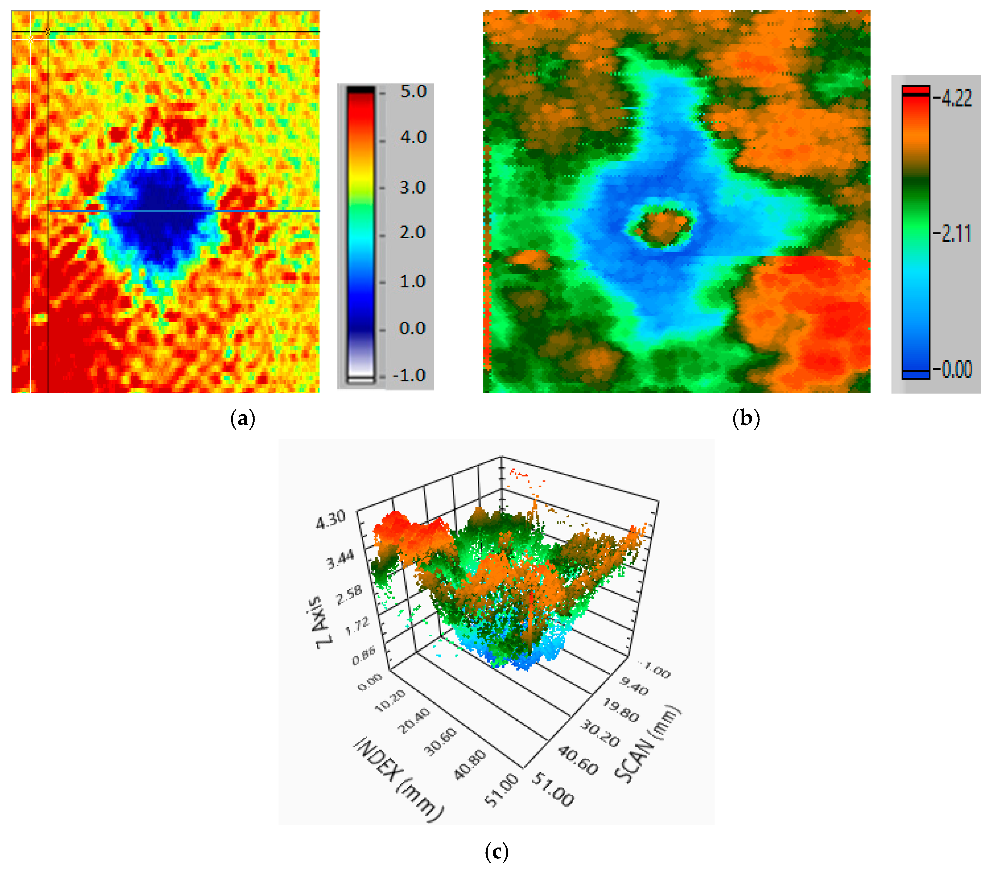
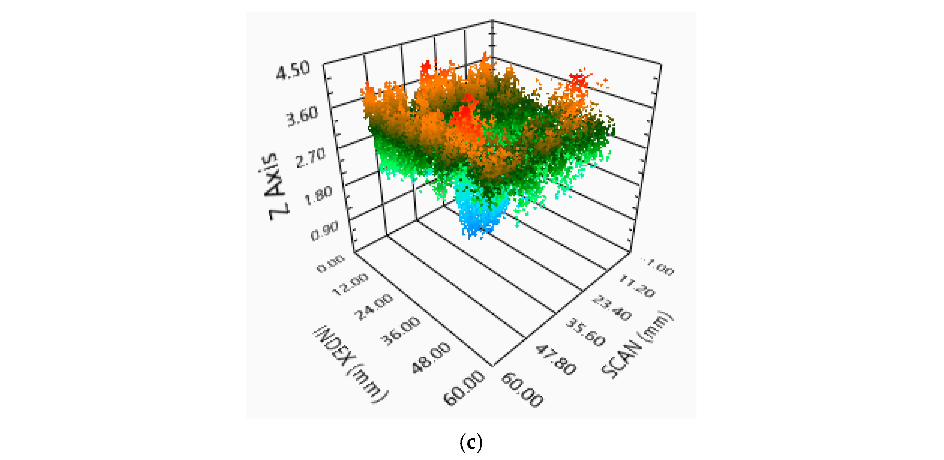
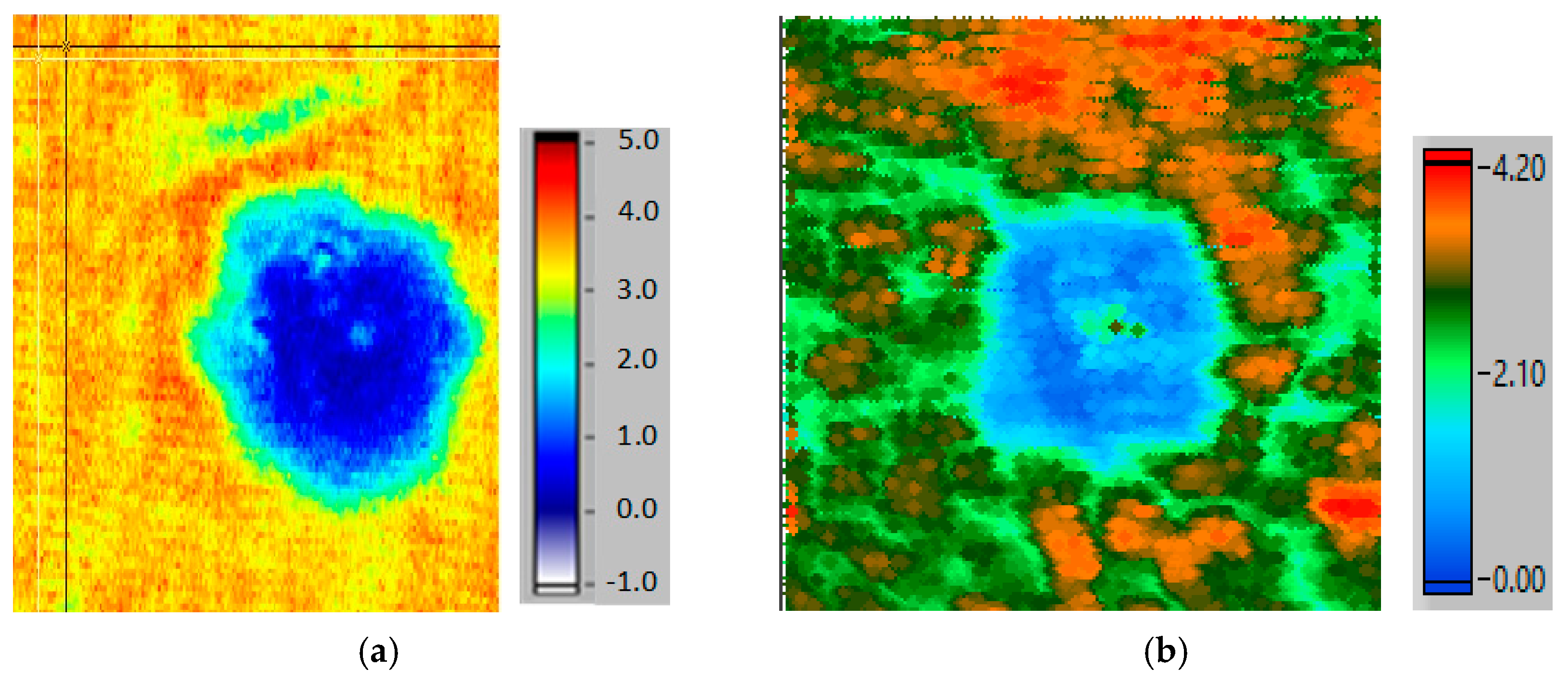
3.2. Ultrasonic C-Scan Inspection of Laminates

Figure 6 and Figure 7 present C-scan images of two composite samples, each containing a single fiber (carbon and Kevlar). The images obtained through air-coupling (40 × 50 mm) and immersion (50 × 50 mm) clearly highlight the extent of damage in both composites, which aligns with the observations and data presented in Table 1. Based on the images in Figure 6a,b, the damage contour in the carbon composite is clearly defined and consistent in both the air-coupled C-scan and the immersion C-scan. In contrast, the Kevlar composite shows more intricate damage ramifications, which are particularly visible when using the immersion C-scan method (see Figure 7b), in contrast to the result shown in Figure 7a. Figure 7c illustrates a 3D representation of the damage in Kevlar, where the shape and extension are more easily evaluated and interpreted. It also allows us to infer about the damage evolution from the impact point to the nearby regions, as we can observe that all impact regions suffered a catastrophic failure. Note that the visible differences in shape for the images of carbon (Figure 6) resulting from the application of both C-scan methods are related with the sample faces from which the signals were acquired. Thus, for the air-coupling C-scan, the amplitude signal captured by the receiver characterizes the damage visualized from the transmitting side (impact side).
On the other hand, the immersion C-scan made use of the backward echo signals of samples. The front and back damage shapes in carbon are illustrated in Figure 8a,b, respectively. The same explanation is valid for the Kevlar images. The color code associated with each type of image characterizes the signal amplitude in volts.
Figure 9 shows the damage in the single glass fiber laminate, obtained through the air-coupling C-scan, allowing for a comparison with the sandwich laminates that have a glass fiber core. The immersion inspection of the glass sample using the 5 MHz probe did not yield satisfactory results due to two factors: reduced thickness and increased attenuation.
The single-fiber composites were analyzed as control samples in this study. The primary objective is to investigate the behavior of composite sandwich structures and to assess how the core material influences the overall performance of the sandwich composite. For these sandwich structures, the same analysis conducted on single-fiber composites was applied to characterize their impact response.
Table 3 presents the average values for maximum load, displacement, and elastic energy of the sandwich composite structures, obtained from curves similar to the ones represented in Figure 4 and Figure 5.
By comparing the results in Table 2 with those in Table 3, it can be concluded that sandwich composites exhibit higher maximum load and elastic energy than those presented by single-fiber structures. This is due to the sandwich composites involving two different materials that, when used together, improve the impact response. On the other hand, it can be seen that the lowest impact force is observed for carbon in the case of single fibers, while in the case of sandwiches, the lowest impact force occurs with carbon fibers in the core, and in both situations this lowest impact force value corresponds to the highest displacement value.
To gain a deeper understanding of sandwich composite behavior, the damage extent and pattern in such structures were assessed using the two C-scan methodologies. Figure 10, Figure 11 and Figure 12 show the impact damage images for the sandwich samples shown in Table 3. The evaluation of damage extent led to the results shown in Table 4, in terms of area, which were assessed using Image J software (version 1.54m).
Table 4 shows that the damage area detected by C-scan in air is consistently smaller than that measured by C-scan in immersion. However, the differences are minimal. For the sequences CGC and GKG, the difference is less than 5%, and for GCG, it is lower than 10%. Based on this, it can be said that the air C-scan is an effective method for inspecting the composite structures studied, particularly when the primary focus is on assessing the damage extent. It also has the advantage of being a dry inspection, which makes it much simpler than the immersion method.
As mentioned for samples with a single layer, the damage profile is similar when observed by both C-scan systems. However, if more detailed damage results are required, for instance small-defects evaluation, implying a need for image production with higher resolution, then the immersion method must be used. As can be observed in Figure 10b, Figure 11b and Figure 12b, despite the similarity presented by the two C-scan methods, additional smaller defects are identified when the immersion C-scan is used. This information is vital for applications involving composite structures, especially where the safety of people and property is critical, namely in the case of aerospace and aeronautic structures, where this type of material is usually used.
The impact bending stiffness (IBS) was also obtained from the load–displacement curves for the sandwich composites, resulting in values of 1018 ± 89 Nmm−1 for the CGC sequence, 1584 ± 104 Nmm−1 for the GCG, and 1257 ± 97 Nmm−1 for the GKG.
Comparing Figure 6 and Figure 11, it can be seen that the form of damage is defined, with few branches (Figure 6b), although some matrix breakage can be seen as the fibers are exposed. In Figure 11, the greatest damage appears sensitively in the middle of the specimen thickness, i.e., in the core, with a well-defined shape and in total agreement with Figure 6. The same conclusion can be drawn when comparing Figure 7 and Figure 12. With regard to the damage seen in Figure 9, it can be concluded that the shape is quite different from that in Figure 6 and Figure 7. In fact, in the case of glass fibers, the damage is very branched, and it is not possible to define a shape. In Figure 10, the larger damage that appears in the core, roughly halfway through the thickness of the specimen, also shows considerable branching, and it is also not possible to identify a shape for the damage.
A relationship can be observed between the damaged area, the elastic energy, and the IBS. For example, for the sandwich composites, an increase in damage area is associated with a decrease in elastic energy and IBS. When comparing IBS values between monolayer and sandwich laminates, it is clear that the GCG configuration, with a carbon core, achieves the highest IBS value at 1584 Nmm−1. This aligns with the high IBS value of the single-fiber carbon samples (1011 Nmm−1), both of which surpass the other configurations. Figure 11 illustrates that an increase in IBS results in a reduction in damage size. Figure 11c gives a 3D view of the damage behavior, clearly depicting the reduced damage size in the impact region due to the “skin” glass layers, which provide superior strength to the composite.
The configuration CGC, with a glass core, is the one with the worst performance, presenting an IBS value of 1018 Nmm−1 and consequently a higher damage, as illustrated in Figure 10. This also aligns with the IBS value for the glass single fiber, which is 667 Nmm−1, the lowest of all. The results of the two C-scan methods, shown in Figure 10, are the most dissimilar compared with the ones with respect to the other laminate configurations. This can be justified by the inability of the air-coupling C-scan to discriminate among small discontinuities or failures.
Based on the findings of this study, the core plays a crucial role in the structural response of hybrid composites when subjected to impact. Table 2 illustrates that the elastic energy of the glass fiber composite is higher than that of the carbon composite, while the IBS of glass is lower than that of carbon. These conclusions indicate that the damage to glass is more extensive than to carbon, as illustrated in Figure 6 and Figure 9, where the glass damage area is broader and more branched. Therefore, when comparing a hybrid composite with a glass core to one with a carbon core, it can be expected that the composite with the glass core will exhibit greater damage.

4. Conclusions

In this work, the authors constructed laminates with a sandwich-structured design using different types of fibers. The outer layers, or “skins”, were made from the same type of fiber, while the inner layer, or “core”, consisted of a different fiber type. The objective was to enhance the damage resistance and tolerance of composite materials. The research encompassed carbon, glass, and Kevlar fibers, first in a single-fiber configuration, then in a sandwich approach. Then, the different configurations were submitted to low-velocity impact tests to produce damages. The next step involved assessing the extent and pattern of damage in the various samples, using ultrasonic C-scan techniques, complemented by an assessment of impact bending stiffness (IBS), which is widely used to evaluate the structural response of composites.
The main conclusions that can be drawn from this study are:
  • Sandwich composites have a higher maximum load and elastic energy than single-fiber structures. In the case of the sandwich composites, the lowest impact force determined was 4221 N, while for the single fiber, the maximum value for the impact force was 2875 N, which means a difference of around 32%. Comparing the elastic energy, the sandwich composite with Kevlar in the core has the highest value (26.9%), around 24% higher than the single-Kevlar-fiber one.
  • The lowest impact force is observed with carbon fibers in the case of single fibers, and for sandwich structures, the lowest impact force occurs when carbon fibers are used in the core. However, the sandwich composite with carbon in the core has a 46% higher impact force value than the single-carbon-fiber composite.
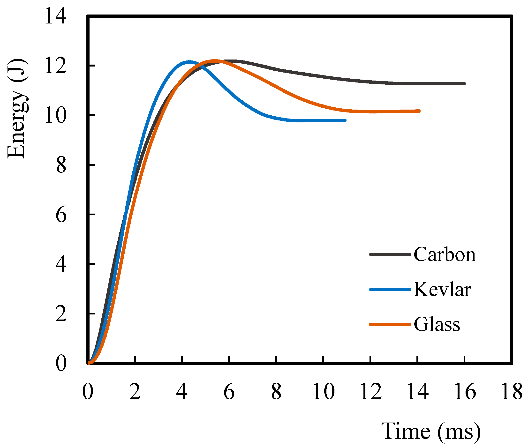
  • The IBS derived from the load–displacement curves indicated that, for the sandwich configurations, a higher IBS value corresponds to a smaller damage size.
  • Carbon fibers, being brittle, show very localized damage, which corresponds to a higher IBS.
  • In the case of glass fibers with some ductility, several ramifications can be observed, which correspond to fragmentation, and hence a lower IBS.
  • On the other hand, Kevlar fibers, which are more ductile, show a damage propagation mode between those of the other two types, as also observed for the IBS value.
  • This finding was validated using the C-scan technique, particularly the immersion method. The GCG configuration demonstrated superior performance in mitigating damage compared to the other sandwich designs.
  • The core is primarily responsible for the structural response in sandwich composites.
In summary, this study is highly significant due to the increasing use of sandwich composites. Understanding that the core is the primary factor influencing the composite’s response allows for the selection of the most suitable configuration tailored to the specific requirements of the designed composite structure. Additionally, based on an understanding of the core’s response, sandwich composites can be designed to meet the desired properties, both in terms of structural performance and the overall weight of the final structure. The core material was verified in this study as the main factor influencing the response of the sandwich composite.

Author Contributions

Conceptualization, formal analysis, methodology: J.S., P.N.B.R. and A.M.A.; writing—original draft preparation: J.S. and A.M.A.; validation, writing—review and editing: J.S., P.N.B.R., M.S. and A.M.A. All authors have read and agreed to the published version of the manuscript.

Funding

This research received no external funding.

Data Availability Statement

The original contributions presented in this study are included in the article. Further inquiries can be directed to the corresponding author.

Acknowledgments

This research is sponsored by national funds through FCT—Fundação para a Ciência e a Tecnologia, under projects UID/00285—Centre for Mechanical Engineering, Materials, and Processes and LA/P/0112/2020.

Conflicts of Interest

The authors declare no conflicts of interest.

References

  1. Chen, S.; Hu, J.; Han, S.; Guo, Y.; Belzile, N.; Deng, T. A review on emerging composite materials for cesium adsorption and environmental remediation on the latest decade. Sep. Purif. Technol. 2020, 251, 117340. [Google Scholar] [CrossRef]
  2. Tornero, R.G. Composite materials are more present today than ever before in cars. Reinf. Plast. 2015, 59, 131. [Google Scholar] [CrossRef]
  3. Hsissou, R.; Seghiri, R.; Benzekri, Z. Miloudi Hilali, Mohamed Rafik, Ahmed Elharfi, Polymer composite materials: A comprehensive review. Compos. Struct. 2021, 262, 113640. [Google Scholar] [CrossRef]
  4. Parveez, B.; Kittur, M.I.; Badruddin, I.A.; Kamangar, S.; Hussien, M.; Umarfarooq, M.A. Scientific Advancements in Composite Materials for Aircraft Applications: A Review. Polymer 2022, 14, 5007. [Google Scholar] [CrossRef]
  5. Adams, R.D.; Cawley, P.D. A review of defects types and non-destructive testing techniques for composites and bonded joints. NDT Int. 1998, 21, 208–222. [Google Scholar]
  6. Amaro, A.M.; Reis, P.N.B.; de Moura, M.F.S.F.; Santos, J.B. Damage detection on laminated composite materials using several NDT techniques. Insight 2012, 54, 14–20. [Google Scholar] [CrossRef]
  7. Tabatabaeian, A.; Fotouhi, S.; Fotouhi, M. 2-Visual inspection of impact damage in composite materials. In Non-Destructive Testing of Impact Damage in Fiber-Reinforced Polymer Composites; Woodhead Publishing Series in Composites Science and Engineering; Woodhead Publishing: Sawston, UK, 2024; pp. 43–67. [Google Scholar] [CrossRef]
  8. Tabatabaeian, A.; Jerković, B.; Harrison, P.; Marchiori, E.; Fotouhi, M. Barely visible impact damage detection in composite structures using deep learning networks with varying complexities. Compos. Part B Eng. 2023, 264, 110907. [Google Scholar] [CrossRef]
  9. Davies, G.A.O.; Hitchings, D.; Zhou, G. Impact damage and residual strengths of woven fabric glass/polyester laminates. Compos. Part A Appl. Sci. Manuf. 1996, 27, 1147–1156. [Google Scholar] [CrossRef]
  10. de Moura, M.F.S.F.; Marques, A.T. Prediction of low velocity impact damage in carbon–epoxy laminates. Compos. Part A Appl. Sci. Manuf. 2002, 33, 361–368. [Google Scholar] [CrossRef]
  11. Amaro, A.M.; de Moura, M.F.S.F.; Reis, P.N.B. Residual strength after low velocity impact in carbon–epoxy laminates. Mater. Sci. Forum 2006, 514–516, 624–628. [Google Scholar] [CrossRef]
  12. Amaro, A.M.; Reis, P.N.B.; de Moura, M.F.S.F. Delamination effect on bending behaviour in carbon–epoxy composites. Strain 2011, 47, 203–208. [Google Scholar] [CrossRef]
  13. Reis, P.N.B.; Ferreira, J.A.M.; Antunes, F.V.; Richardson, M.O.W. Effect of interlayer delamination on mechanical behavior of carbon/epoxy laminates. J. Compos. Mater. 2009, 43, 2609–2621. [Google Scholar] [CrossRef]
  14. Baran, I.; Weijermar, W. Residual bending behaviour of sandwich composites after impact. J. Sandw. Struct. Mater. 2020, 22, 402–422. [Google Scholar] [CrossRef]
  15. Mallick, P.K. Fibre-Reinforced Composites Materials, Manufacturing and Design, 3rd ed.; Taylor & Francis Group: New York, NY, USA, 2007; p. 616. [Google Scholar]
  16. Chandrasekar, M.; Shahroze, R.M.; Ishak, M.R.; Saba, N.; Jawaid, M.; Senthilkumar, K.; Senthil Muthu Kumar, T.; Siengchin, S. Flax and sugar palm reinforced epoxy composites: Effect of hybridization on physical, mechanical, morphological and dynamic mechanical properties. Mater. Res. Express 2019, 6, 105331. [Google Scholar] [CrossRef]
  17. Hassan, M.Z.; Cantwell, W.J. The influence of core properties on the perforation resistance of sandwich structures—An experimental study. Compos. Part B Eng. 2012, 43, 3231–3238. [Google Scholar] [CrossRef]
  18. Hung, P.; Lau, K.; Cheng, L.; Leng, J.; Hui, D. Impact response of hybrid carbon/glass fibre reinforced polymer composites designed for engineering applications. Compos. Part B Eng. 2018, 133, 86–90. [Google Scholar] [CrossRef]
  19. Chen, D.; Luo, Q.; Meng, M.; Li, Q.; Sun, G. Low velocity impact behavior of interlayer hybrid composite laminates with carbon/glass/basalt fibres. Compos. Part B Eng. 2019, 176, 107191. [Google Scholar] [CrossRef]
  20. Cheon, J.; Lee, M.; Kim, M. Study on the stab resistance mechanism and performance of the carbon, glass and aramid fiber reinforced polymer and hybrid composites. Compos. Struct. 2020, 234, 111690. [Google Scholar] [CrossRef]
  21. Zhang, C.; Rao, Y.; Li, W. Low-velocity impact behavior of intralayer hybrid composites based on carbon and glass non-crimp fabric. Compos. Struct. 2020, 234, 111713. [Google Scholar] [CrossRef]
  22. Liu, H.; Falzon, B.G.; Tan, W. Experimental and numerical studies on the impact response of damage-tolerant hybrid unidirectional/woven carbon-fibre reinforced composite laminates. Compos. Part B Eng. 2020, 136B, 101–118. [Google Scholar] [CrossRef]
  23. Bian, T.; Lyu, Q.; Fan, X.; Zhang, X.; Li, X.; Guo, Z. Efects of Fiber Architectures on the Impact Resistance of Composite Laminates Under Low-Velocity Impact. Appl. Compos. Mater. 2022, 29, 1125–1145. [Google Scholar] [CrossRef]
  24. ASTM D 7136. ASTM International: West Conshohocken, PA, USA. 2020. Available online: https://www.astm.org/d7136_d7136m-15.html (accessed on 2 January 2025).
  25. Monjon, A.; Santos, P.; Valvez, S.; Reis, P.N.B. Hybridization effects on bending and interlaminar shear strength of composite laminates. Materials 2022, 14, 1302. [Google Scholar] [CrossRef] [PubMed]
  26. David-West, O.S.; Nash, D.H.; Banks, W.M. An experimental study of damage accumulation in balanced CFRP laminates due to repeated impact. Compos. Struct. 2008, 83, 247–258. [Google Scholar] [CrossRef]
  27. David-West, O.S.; Nash, D.H.; Banks, W.M. Low-velocity heavy mass impact response of singly curved composites. Proc. Inst. Mech. Eng. Part L J. Mater. Des. Appl. 2014, 228, 17–33. [Google Scholar] [CrossRef]
  28. Aslan, Z.; Karakuzu, R.; Okutan, B. The response of laminated composite plates under low-velocity impact loading. Compos. Struct. 2003, 59, 119–127. [Google Scholar] [CrossRef]
  29. Hosur, M.V.; Adbullah, M.; Jeelani, S. Studies on the low-velocity impact response of woven hybrid composites. Compos. Struct. 2005, 67, 253–262. [Google Scholar] [CrossRef]
  30. Iqbal, K.; Khan, S.-U.; Munir, A.; Kim, J.-K. Impact damage resistance of CFRP with nanoclay-filled epoxy matrix. Compos. Sci. Technol. 2009, 69, 1949–1957. [Google Scholar] [CrossRef]
  31. Amaro, A.M.; Reis, P.N.B.; Neto, M.A.; Louro, C. Effects of alkaline and acid solutions on glass/epoxy composites. Polym. Degrad. Stab. 2013, 98, 853–862. [Google Scholar] [CrossRef]
  32. Amaro, A.M.; Reis, P.N.B.; Neto, M.A. Experimental study of temperature effects on composite laminates subjected to multi-impacts. Compos. Part B Eng. 2016, 98, 23–29. [Google Scholar] [CrossRef]
  33. Khashaba, U.A. A comprehensive study of low-velocity impact behavior and damage evaluation of angle-ply thin woven GFRP composites under elevated temperatures. Compos. Sci. Technol. 2024, 252, 110608. [Google Scholar] [CrossRef]
  34. Newaz, G.M.; Walsh, D.J. Interrelationship of damage and strain in particulate composites. J. Comp. Mater. 1989, 23, 326e36. [Google Scholar] [CrossRef]
  35. Chow, C.L.; Wang, J. An anisotropic theory of elasticity for continuum damage mechanics. Int. J. Fract. 1987, 33, 3e16. [Google Scholar] [CrossRef]
  36. Morais, W.A.; Monteiro, S.N.; d’Almeida, J.R.M. Evaluation of repeated low energy impact damage in carbon-epoxy composite laminates. Compos. Struct. 2005, 67, 307e15. [Google Scholar] [CrossRef]
  37. Aktas, M.; Atas, C.; Icten, B.M.; Karakuzu, R. An experimental investigation of the impact response of composite laminates. Compos. Struct. 2009, 87, 307–313. [Google Scholar] [CrossRef]
Figure 1. (a) Dimensions of the specimens (in mm); (b) aspect of the cross-sectional view of Kevlar specimens; (c) aspect of the cross-sectional view of CGC specimens.
Jcs 09 00086 g001
Figure 2. Immersion C-scan.
Jcs 09 00086 g002
Figure 3. Air-coupling C-scan.
Jcs 09 00086 g003
Figure 4. Energy–time curves for composites with single fiber.
Jcs 09 00086 g004
Figure 5. Load–displacement curve for all composites with single fiber.
Jcs 09 00086 g005
Figure 6. Damage images for the carbon sample with a single fiber: (a) air-coupling C-scan (xx = 40 mm; yy = 50 mm); (b) immersion C-scan (xx = 50 mm; yy = 50 mm).
Jcs 09 00086 g006
Figure 7. Damage images for the Kevlar sample with a single fiber: (a) air-coupling C-scan (xx = 40 mm; yy = 50 mm); (b) immersion C-scan (xx = 50 mm; yy = 50 mm); (c) 3D image.
Jcs 09 00086 g007
Figure 8. Carbon sample: (a) front damage; (b) back damage.
Jcs 09 00086 g008
Figure 9. Damage image for the glass sample with a single fiber by air-coupling C-scan (xx = 40 mm; yy = 50 mm).
Jcs 09 00086 g009
Figure 10. Damage images for the carbon–glass–carbon sample: (a) air-coupling C-scan (xx = 40 mm; yy = 50 mm); (b) immersion C-scan (xx = 50 mm; yy = 50 mm).
Jcs 09 00086 g010
Figure 11. Damage images for the glass–carbon–glass sample: (a) air-coupling C-scan (xx = 40 mm; yy = 50 mm); (b) immersion C-scan (xx = 50 mm; yy = 50 mm); (c) 3D image.
Jcs 09 00086 g011aJcs 09 00086 g011b
Figure 12. Damage images for the glass–Kevlar–glass sample: (a) air-coupling C-scan (xx = 40 mm; yy = 50 mm); (b) immersion C-scan (xx = 50 mm; yy = 50 mm).
Jcs 09 00086 g012
Table 1. Sample stacking sequence and respective average thickness.
Stacking SequenceAverage Thickness (mm)
12C2.1
12G1.8
12K2.1
4C + 4G + 4C2.7
4G + 4C + 4G2.8
4G + 4K + 4G2.7
Table 2. Average and standard deviation (in brackets) values of the maximum load and displacement as well as elastic energy, for composites with single fibers.
CompositeMaximum Load (N)Maximum Displacement (mm)Elastic Energy (%)
C2276 (76)7.5 (0.6)7.0 (0.6)
K2875 (56)6.2 (0.3)20.4 (1.7)
G2372 (79)7.6 (0.2)16.9 (1.4)
Table 3. Average and standard deviation (in brackets) values of the maximum load and displacement, as well as elastic energy, for the sandwich composites.
CompositeMaximum Load (N)Maximum Displacement (mm)Elastic Energy (%)
4C + 4G + 4C4782 (217)3.8 (0.2)16.8 (1.5)
4G + 4C + 4G4221 (192)4.4 (0.1)25.9 (2.1)
4G + 4K + 4G4674 (369)4.3 (0.1)26.9 (2.6)
Table 4. Damage area for composite sandwich evaluated by C-scan.
Damage Area (mm2)Stacking Sequence
4C + 4G + 4C4G + 4C + 4G4G + 4K + 4G
Air-Coupling C-Scan714.4 ± 32.1184.8 ± 11.6531.9 ± 31.8
Immersion C-Scan741.4 ± 42.2201.8 ± 17.2553.9 ± 32.4
Disclaimer/Publisher’s Note: The statements, opinions and data contained in all publications are solely those of the individual author(s) and contributor(s) and not of MDPI and/or the editor(s). MDPI and/or the editor(s) disclaim responsibility for any injury to people or property resulting from any ideas, methods, instructions or products referred to in the content.

