Article

Development and Validation of a Desktop 3D Printing System with Thermo-Mechanical In Situ Consolidation for Continuous Fiber-Reinforced Polymer Composites

by
Hannes Oberlercher
1,2,
Marius Laux
2,
Gean Henrique Marcatto de Oliveira
1,* and
Sergio T. Amancio-Filho
1,*
1
Institute of Material Science, Joining and Forming—Professorship “Aviation Materials and Manufacturing Techniques”, Graz University of Technology, 8010 Graz, Austria
2
ADMiRE Research Center, Carinthia University of Applied Sciences, 9524 Villach, Austria
*
Authors to whom correspondence should be addressed.
J. Compos. Sci. 2025, 9(3), 128; https://doi.org/10.3390/jcs9030128
Submission received: 10 February 2025 / Revised: 26 February 2025 / Accepted: 27 February 2025 / Published: 10 March 2025
(This article belongs to the Special Issue Polymer Composites and Fibers, 3rd Edition)

Abstract

:
A controlled laminate consolidation is one of the most essential approaches in the production of fiber-reinforced thermoplastics components. With the use of specific consolidation models, almost the entire strength potential of the material can be exploited. However, a controlled thermo-mechanical in situ consolidation (TMIC) strategy in the fused filament fabricated (FFF) process of continuous fiber-reinforced polymer composites (CFRPC) has not been considered so far and leads to deconsolidation defects in the 3D-printed material. These defects in terms of micro and macro volumetric flaws in the joining zone indicate a poor process parameter selection and inadequate thermo-mechanical consolidation. These imperfections lead to a reduction in the fiber volume content and a significant deterioration in the mechanical properties. In this work, a self-developed test rig is presented, which is able to influence and monitor the consolidation during the additive manufacturing (AM) process with a TMIC unit in a controlled manner. To evaluate the test rig, the mechanical construction and the implemented sensors were tested for full functionality. Subsequently, test specimens were fabricated for mechanical characterization using three-point bending (3PB) tests and microstructural analysis. Based on these results, the influence of TMIC, with its dependent process parameters (consolidation force, temperature, printing speed), is presented. A perspective on the future development of controlled consolidation in AM of CFRPC is shown.

Graphical Abstract

1. Introduction

The effort to establish a functioning circular economy is transforming many industrial sectors, particularly in mechanical engineering, medical technology, the automotive industry, and aviation. A potential solution for these industries is the use of additive manufacturing (AM), commonly known as 3D printing. This technology offers multiple benefits simultaneously, as follows: (a) the 3D printing allows for economical and resource-efficient production of complex-shaped components [1], (b) it facilitates advanced lightweighting concepts, significantly reducing greenhouse gas emissions in the transportation industry [2], (c) 3D printing is considered a disruptive technology with the potential to radically change current manufacturing methods, enabling the development of localized material recycling and manufacturing loops [3], and (d) it enables product personalization and serves as a key technology for mass customization [4].
The global market for 3D-printed polymer composite materials reached a value of USD 452.5 million in 2023, surpassing earlier projections, with further growth expected to reach USD 4.13 billion by 2030 at a compound annual growth rate (CAGR) of 37.2% [5,6]. This growth highlights the technology’s promise across industries where weight reduction is critical.
Fused filament fabricated (FFF) 3D-printing processes for continuous fiber-reinforced polymer composites (CFRPC) has been commercially available for approximately nine years. Today, numerous companies offer CFRPC filaments and related 3D-printing technologies. Both desktop systems, such as those developed by Markforged Inc. (Watertown, MA, USA), Anisoprint (Suzhou, China), Desktop Metal (Burlington, MA, USA), APS Tech Solutions (Ellwangen, Germany), and 9T Labs (Zurich, Switzerland), as well as advanced industrial robotic systems from companies like Arevo (California, CA, USA), CEAD (Delft, The Netherlands), and Mantis Composites (California, CA, USA), are widely used to address diverse manufacturing challenges [7].
In the FFF process of CFRPC, a filament is deposited onto a previously printed material through a heated nozzle, forming a compact component. This approach allows CFRPC fibers to be oriented along principal stress directions, optimizing material utilization. However, challenges remain, particularly with weak interlayer bonding due to insufficient fusion between deposited layers and high material porosity in the form of micro- and macrovoids [8,9]. The void content is primarily caused by insufficient control over deconsolidation behavior behind the print nozzle [10]. Controlling this porosity is challenging and leads to significant variability in material properties [11]. To address these issues, 9T Labs has implemented an autoclave process to reduce void content post-printing, albeit at the expense of increased time and costs [12,13]. A more integrated alternative is thermo-mechanical in situ consolidation (TMIC) rolls, which apply localized heat and pressure during printing, significantly reducing porosity compared to processes without compaction [14]. TMIC improves interlayer bonding, eliminates the need for post-processing, and enhances process efficiency. However, it also requires precise force and temperature control, presents challenges in hardware integration, and may introduce residual stresses.
What is still missing is a full understanding of the interaction of the different parameters in CFRPC printing with TMIC rolls, especially the correlation between material parameters (fiber, matrix), process parameters (force, temperature, time), and emerging material porosity [15,16]. To overcome existing limitations, we have developed an advanced test rig with integrated sensors, enabling precise real-time monitoring and analysis of CFRPC printing. This system provides unique insights into the correlation between process parameters and material properties, laying the foundation for an optimized consolidation model that surpasses existing solutions.
This paper outlines the experimental setup of the test rig (hardware and software), validates the test bench results, and discusses initial 3D-printed outcomes.

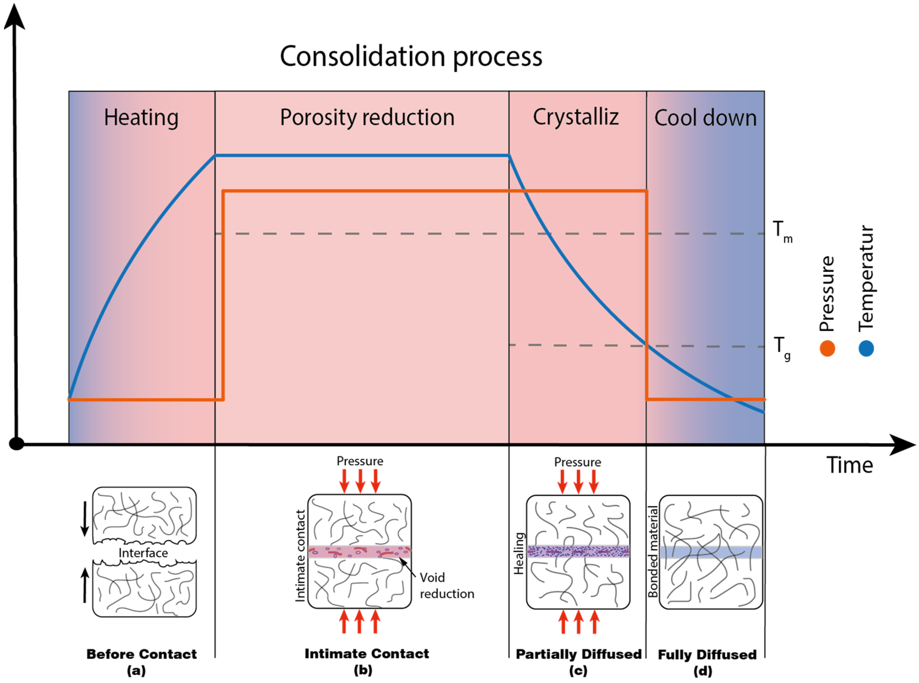
2. Basics of Consolidation Thermoplastic Composites

2.1. Fundamentals

Consolidation is a joining process where physical processes result in the formation of strength at the joint [17,18,19,20,21,22,23,24]. It is essential for transforming pre-impregnated fiber (Prepreg) layers into a solid laminate and creating a monolithic structure. The joining process can be divided into the two sub-mechanisms of laminate densification and molecular penetration. Applying consolidation pressure within the crystallinity temperature range of the matrix material is necessary to minimize the formation of voids and the presence of other solvents or moisture [25]. During consolidation, several phenomena occur, such as intimate contact between plies, interlaminar adhesion, fiber deformation and movement, and molecular diffusion. These processes lead to complex interactions that are influenced by the settings of the process parameters.
During molecular interpenetration, thermal activation facilitates diffusion of polymer chains in the joining zone, enabling the formation of new intermolecular bonds. Thus, with additional contact pressure, the voids and interfaces gradually disappear, and the mechanical strength of the joint is created [26].
The production of thermoplastic composites involves the three distinct physical processes of melting, porosity reduction, and cooling, as illustrated in Figure 1a–d. First, during the heating phase (Figure 1a), the laminate is heated above the melting temperature of the polymer material, increasing the chain mobility of the polymer and strengthening chain diffusion. This reduces deformation resistance and facilitates contact formation between the joining layers under the application of a force with a defined contact area. As the process progresses, porosity decreases significantly, as shown in Figure 1b,c, where the fusion of polymer surfaces occurs through contact development and surface diffusion. Finally, during the cooling phase (Figure 1c), depending on the cooling rate, the polymer transitions into an amorphous or semi-crystalline morphology, completing the consolidation process.
The consolidation process involves different temperature and pressure developments, which affect the porosity and fiber distribution in the laminate. Process simulations with integrated material models and transient temperature and pressure distribution calculations can predict process parameters and optimize the process and material quality accordingly [27,28,29,30,31].

2.2. In Situ Consolidation of Thermoplastic Continuous Fibers

In situ consolidation of thermoplastic composites opens the possibility of fully automated composite production. This process step is fast and efficient in the production of complex-shaped fiber composite components and is able to save time and costs. This process is increasingly used in the aerospace industry because of its high component quality and flexibility.
One of the most popular in situ consolidation concepts is automated tape laying (ATL). Figure 2 shows a schematic representation of the principles of the thermoplastic taping process. A thermoplastic unidirectional tape layer, which comes from a spool via a transport guide system, is heated and positioned on the substrate (laminate) next to the previously placed tape without gaps or overlaps. For the heat sources, there are several variations. The joining zone in Figure 2 is brought to a melting temperature using hot gas. Infrared or laser technology for heating the tape and substrate is also available for ATL processes. This is to ensure that the thermoplastic matrix of the Prepreg tape and that of the substrate are brought to a temperature above the glass temperature or melting temperature. The intimate contact between substrate and Prepreg tape is implemented by means of an in situ consolidation roller. The in situ consolidation roller applies controlled pressure with a specific force and contact area, welding the two joining partners into a laminate. In most technical applications, it also serves as a heat sink to cool the laminate. Thus, the ATL process is divided into the three process steps of heating, consolidation, and cooling. In some cases, a second in situ consolidation roller is used during the process to perform post-consolidation, improving the quality of the composite [25]. This strategy optimizes the consolidation process by precisely replicating the phases of heating, consolidation for porosity reduction, and post-consolidation at crystallization temperature to minimize deconsolidation effects of the laminate, as shown in the diagram in Figure 1.

2.3. 3D-Printed Strategies of Thermoplastic Continuous Fibers

In terms of technology, there are only minor differences between CFRPC 3D printers and conventional FFF 3D printers. Nevertheless, there exist many methodologies for blending reinforcing fibers with thermoplastic matrix material. Anisoprint (Suzhou, China) and other manufacturers have opted to combine CFRPC and matrix material within a mixing chamber located in the print head during the printing process (see Figure 3a). This has the benefit of being able to blend various matrix materials with different CFRPC reinforcements. Thus, depending on the material, individual components can be constructed in accordance with the corresponding mechanical or thermal stress.
Conversely, the company Markforged Inc. utilizes Prepreg material. The Prepreg material is commonly produced using a carefully regulated procedure. Initially, reinforcing fibers, such as carbon or glass, are thoroughly saturated with a thermoplastic matrix in a consistent and regulated manner. Following impregnation, the material is then dried and stored in sealed boxes to prevent any moisture absorption from the surrounding environment. During the production process, the filament is transported using a filament feeder to the heated nozzle where it is melted and deposited on the printing bed layer by layer (see Figure 3b).
Both technical approaches differ only in the pre-treatment of the fiber with the respective matrix material; the fiber laying and consolidation process works with the same technological approach.
The coating process also has an effect on the quality of the composite [32], but is not investigated or considered in this work. In this work, the technological approach with pre-impregnated Prepreg filaments is used, as this is the most common method and numerous studies of laminate quality have been published [11,33,34,35,36].

2.4. Consolidation Strategies of 3D-Printed Thermoplastic Continuous Fibers

In the conventional 3D-printing of CFRPC, such as the Markforged Inc. technology, consolidation is achieved using a modified nozzle tip. In the upper section of the nozzle, there is a PTFE isolation tube (see Figure 4a) that prevents the matrix material of the Prepreg filament from melting prematurely, ensuring that it only melts in the designated polymer melting zone, as shown in Figure 3b. The consolidation zone is approximately 533 µm wide, with the nozzle’s filament exit diameter expanding from 1 mm to 1.9 mm. The filament is guided from the nozzle to the consolidation surface along a radius of 232 µm (see Figure 4b,c).
The Prepreg filaments from Markforged Inc. have a diameter of approximately 0.4 mm, as shown in Figure 5. During the consolidation process, the filament is flattened on the print bed to a width of 0.9 mm to 1.2 mm (see schematic representation in Figure 6a,b), which has also been demonstrated in other studies [37].
However, microstructural analyses show a high level of imperfections in the Markforged CFRPC laminate composed of carbon fibers (CF) and a polyamide 6 (PA6) matrix (see Figure 5b). The relatively high void content of up to 12% [8,38], which also leads to an inhomogeneous distribution of fibers within the matrix, significantly contributes to the deterioration in the mechanical properties [9,14,39,40,41].
These imperfections are partly due to the significantly shortened consolidation time in the 3D-printing process. Since consolidation occurs while the matrix material is still at melting temperature, the layers are quickly compressed and bonded, but there is insufficient time for full curing. This affects structural integrity and can lead to deconsolidation effects [15,42,43,44,45].
However, previous studies have shown that the mechanical properties of composite materials can be improved by increasing the applied pressure and systematically reducing the layer height [16,46]. Figure 6 illustrates the effects of these adjustments: (a) shows how the force F K applies the desired layer height reduction to the filament, (b) depicts the filament flattened in width by the applied force F K , and (c) demonstrates the resulting mechanical stress v ( z ) between the nozzle and the filament. In particular, reducing the layer height leads to a significant increase in stress v ( z ) , which can cause damage to the reinforcement fibers or even result in their pull-out from the matrix. These effects compromise the mechanical properties of the composite material and emphasize the need to balance improved consolidation with the risks of excessive mechanical stresses.
Some approaches to extended consolidation in the 3D printing of CFRPC have already been investigated in detail [14,38,43,47,48,49,50,51,52]. Both post-consolidation in an autoclave and controlled in situ consolidation lead to significant reductions in void content and improvements in mechanical properties. In some cases, post-consolidation reduced the void content by up to 92% [53]. The application of a TMIC roller reduced the void content, which typically ranges from 10% to 12% in conventional CFRPC 3D printing, down to 3% [14]. At the same time, an improvement in mechanical properties, specifically an increase in flexural strength by up to 62%, was achieved. In this study, a consolidation force of 10 N and a consolidation temperature of 270 °C, applied through the contact area of the printing nozzle were used to bond the fiber to the substrate. However, a potential drawback of this method is the risk of deconsolidation effects in the laminate, as the filament, similar to conventional CFRPC 3D printing, remains near melting temperature during application with the TMIC roller. Nevertheless, this study demonstrated that controlled, material-friendly in situ consolidation with a roller can lead to a significant reduction in voids and an enhancement in mechanical properties.
After examining both the conventional CFRPC 3D printing method and the extended consolidation studies, two critical factors in the consolidation process have emerged as particularly relevant. First, the mechanical load from the consolidation unit, which can damage the reinforcing fibers, and second, the consolidation of the filament near the melting temperature, which has been shown to cause deconsolidation effects in the laminate, leading to increased voids in the bonding zone. The best results were achieved through post-consolidation, where a controlled temperature and pressure profile, as shown in Figure 1, was applied. However, this approach has the disadvantage of requiring an additional processing step.

3. System Development
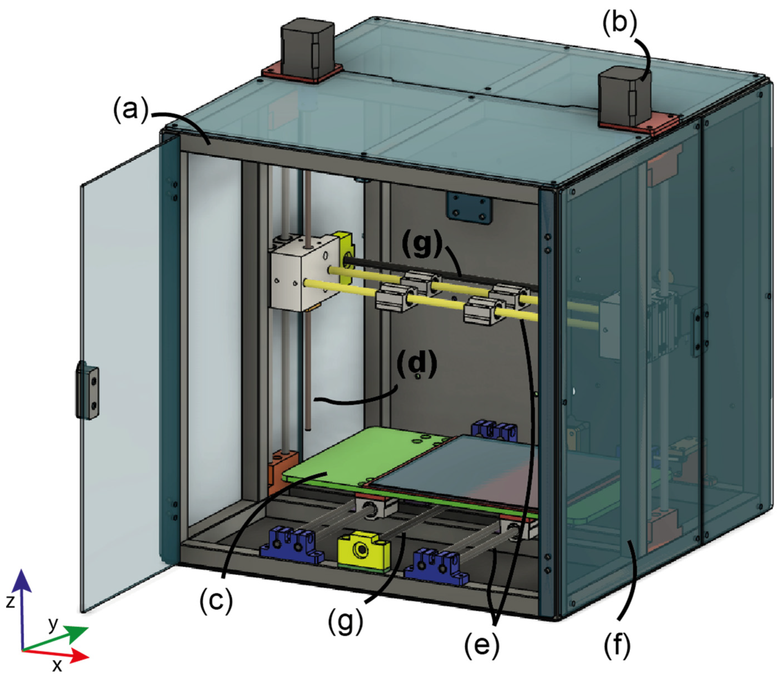
For the development of a consolidation test rig to evaluate the TMIC effects on 3D-printed CFRPC materials, several key design aspects must be considered.
The primary purpose of the test rig is to analyze the influence of TMIC on the material under various process parameters. The goal is not to produce complex component structures but rather to study the effects of factors such as temperature, the force applied through the contact area of the roller, and time on the consolidation of the material.
Preventing deformation of the test rig’s frame housing and print head under increasing consolidation forces presents a critical design challenge. Even the smallest deformations can lead to inaccuracies in the consolidation force and the precise layer height of the material sample, potentially skewing results regarding microstructure and material properties. Due to the additional forces acting on the print head, print bed, and frame structure, a commercially available 3D printer cannot be used as a basis. Therefore, the test rig must be specifically designed to meet these requirements, ensuring structural stability and minimizing deformation.
The thermal expansion of the consolidation unit at elevated temperatures presents an additional challenge. This expansion could lead to measurement inaccuracies, potentially affecting the reliability of the results. Therefore, materials and design details must be carefully selected to minimize these effects.
The selection and placement of sensors, such as those for measuring temperature, force, and speed, are crucial for the precise monitoring and control of the consolidation process. To enable reliable scientific analyses, appropriate sensors for measuring forces, temperature, and positional changes must be integrated at strategic points within the system. These sensors must be capable of detecting even the smallest deviations in the consolidation process.
To control the test rig effectively, it is essential to precisely and reliably adjust process parameters such as consolidation force, temperature, and speed. Existing open-source software was utilized and modified to meet specific requirements, enabling optimal process control and monitoring.

3.1. Hardware

3.1.1. 3D Printer Frame, Axes, and Drive System

The frame construction of the consolidation test rig is based on an aluminum profile selected from the Easy-System profile. The chosen profile has a grid dimension of 20 × 20 mm and belongs to the Nut 6 category (see Figure 7a). The frame geometry was specifically designed for the consolidation test rig to withstand thermal expansions and mechanical forces that occur during the consolidation process. Additionally, the frame provides ample space and mounting options for the motors, sensors, and other mechanical components necessary for the printing process.
The guides for the axes of the print bed and print head are integrated into the frame structure, ensuring stable movement. Vertical loads occurring in the Z-direction, which are particularly relevant during consolidation, are absorbed by reinforcement axes. Four linear axes with intermediate supports are installed for the print bed, and two linear axes are used for the print head (see Figure 7e).
The test rig is based on a 3-axis Cartesian printing system. The heated print bed, equipped with a glass plate (see Figure 7c), moves in the Y-direction, while the print head is positioned along a trapezoidal spindle (M6 × 1 mm) in the Z-direction (see Figure 7d). The drives are powered by NEMA 17 stepper motors (see Figure 7b) with a step angle of 1.8° and operate in full-step mode. This results in the smallest possible step size of 0.005 mm, ensuring very high accuracy in the positioning of the fiber layer height. A Tr8 × 1.5 mm trapezoidal spindle is used for the X- and Y-axes (see Figure 7g), providing sufficient precision for the movements in these axes with the smallest possible step size of 0.0075 mm.
To maintain a consistent build chamber temperature, the frame is lined with polymethylmethacrylate plates (see Figure 7f).

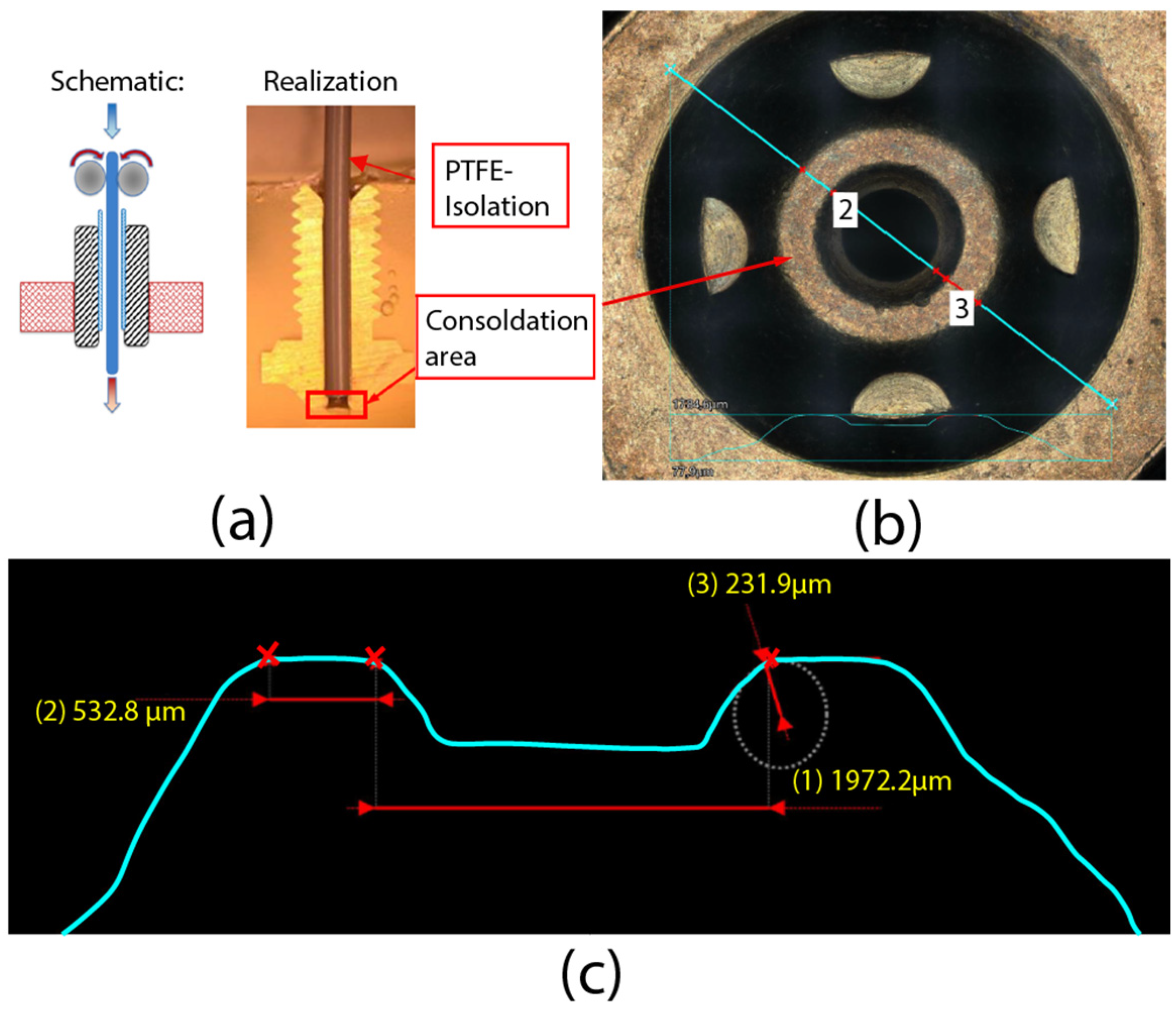
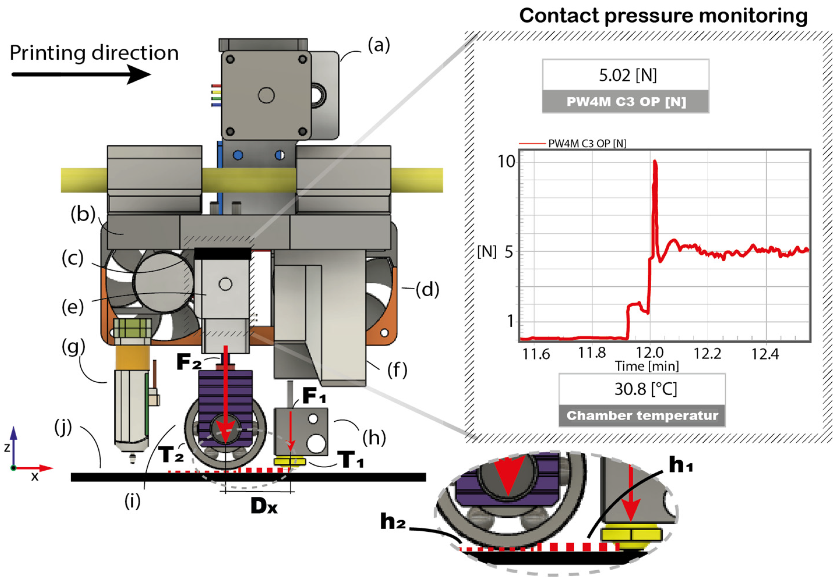
3.1.2. In Situ Consolidation Printing Head

The CFRPC filament is fed towards the hotend (h) via a filament feeder (a) (see Figure 8). The feeding unit incorporates a freewheeling ball-bearing that compensates for tensile stresses and prevents the CFRPC from being pulled out of the molten matrix. This ensures the integrity of the composite material is maintained during the printing process.
Between the filament feeder and the hotend, a filament cutter (f) is positioned, allowing the CFRPC filament to be cut before a change in the printing path or layer height. The distance between the cutter and the nozzle is 50 mm and must be accounted for during G-code programming.
The hotend, equipped with a 3D-printing nozzle designed to meet the geometric requirements shown in Figure 4, a Semitec 104NT thermistor (Tokyo, Japan), and a 12 V, 30 W cartridge heater for precise control of the nozzle temperature T 1 , is height adjustable. This allows for the optimal adjustment of the pre-consolidation force F 1 at the material’s melting temperature to ensure effective pre-consolidation. The BLTouch V3.1 (Songpa-gu, Seoul, Republic of Korea) leveling sensor (g), mounted on the aluminum base plate of the print head, measures the surface of the print bed before each print with a repeatability of approximately 0.005 mm (standard deviation). Irregularities are automatically compensated for using the Z-axis drives, ensuring consistent layer height and consolidation throughout the entire printing process.
A damping unit made of polytetrafluoroethylene (PTFE) (c) serves not only for mechanical damping but also for thermal decoupling, effectively minimizing thermally induced material expansions.
The load cell (e) and the TMIC unit enable the precise control of the consolidation force F 2 which can be measured and monitored throughout the entire process. The TMIC roller (i), with a diameter of 10 mm and a width of 8 mm, is heated by a 12 V, 40 W cartridge heater to precisely regulate the roller temperature T 2 . The roller’s rotation is driven by the applied force on the CFRPC filament and the print bed (j). The TMIC unit is height-adjustable, allowing for the consolidation force to be increased or decreased as needed. The entire assembly, consisting of the consolidation unit, load cell, and PTFE damping element, is mounted on an aluminum carrier plate (b) and is moved along the X-axis using linear bearings.
The distance D x refers to the adjustable spacing between the TMIC roller and the nozzle’s exit opening, allowing precise adjustment of the timing for defined consolidation. During the printing process, two different layer heights can emerge, depending on the consolidation force and the roller’s temperature after the continuous fiber filament is deposited by the nozzle. These layer heights are shown in Figure 8 as h 1 and h 2 .
Fans are strategically positioned (d) to cool components such as the load cell, filament feeder, and cutter, preventing overheating that could lead to measurement inaccuracies or premature heating of the filament. This ensures the functionality and precision of the entire unit are maintained.
It is also crucial to ensure controlled consolidation and optimally align it with the process-dependent parameters. The precise positioning of individual components is essential to accurately analyze the effects of various process parameters on the composite material. Table 1 provides an overview of the adjustable parameters for the PA6 matrix material used in the system, which can also be adapted for other matrix materials as needed.

3.1.3. Sensors

To monitor the consolidation processes during the production of 3D-printed CFRPC materials, carefully selected sensors must be employed. These sensors are tasked with collecting critical data throughout the manufacturing process, which is essential for subsequent analysis. At the same time, they enable the continuous control of process parameters during the entire production cycle. This ensures that deviations, such as fluctuations in temperature or applied force, are avoided, preventing imperfections in the material.
In Figure 9a, the side view of the test rig is shown. An infrared camera, positioned 100 mm away from the test object, captures the layers oriented perpendicular to the printing direction. This configuration allows the determination of the temperature gradient along the printing direction of the deposited filament, enabling the measurement of temperatures in the bonding and consolidation zones of the material. To ensure high image quality, the interior surfaces of the housing were lined with matte black panels to minimize reflections during imaging. Additionally, the load cell, located above the axis of the TMIC roller, is shown. It is cooled by fans to ensure that the operating temperature does not exceed 60 °C, maintaining consistent measurement accuracy. Furthermore, Semitec 104NT (Tokyo, Japan) thermistors are installed in the print bed and the nozzle. PT100 sensors (Kleinostheim, Germany) are used to measure the temperature inside the chamber.
Figure 9b shows the front view of the test rig, featuring a bed-leveling sensor that measures the print bed before each printing process and compensates for irregularities by adjusting the Z-axis. Additionally, a temperature sensor is integrated into the thermo-mechanical consolidation unit and positioned along the central axis of the roller.
Table 2 provides an overview of all sensors integrated into the thermo-mechanical consolidation test rig, including their specifications and designations.

3.2. Software

3.2.1. Printer Control

The GT2560 controller board (Geeetech, New York, NY, USA) is operated using the Repetier-Host V2.3.2 slicer software (Willich, Germany). This software allows for the integration and editing of custom-generated G-codes. Additionally, the temperature of the TMIC unit can be set by integrating an additional print head. The print speed, nozzle temperature, print bed temperature, and fan speed are controlled via a host function on a Windows computer, which is connected to the controller board via USB.

3.2.2. Consolidation Measuring

The force measurement of the TMIC unit is ensured via an HBM QuantumX interface of the MX1615 series (Darmstadt, Germany). The force data are recorded throughout the entire test run using the catmanEasy 5.4.2.11 data acquisition software (Darmstadt, Germany). The sampling rate was set to 10 Hz, and a Bessel characteristic filter was applied to reduce potential noise.

3.2.3. Infrared Measuring

The recordings made with the Testo 890 infrared camera (Titisee-Neustadt, Germany) are controlled and analyzed using the IRSoft V5.1 software from Testo (Titisee-Neustadt, Germany). For the analysis, precise measurement points and lines can be defined to detect temperature gradients, with the data being recorded and stored in tabular format.

4. Functionality of the Consolidation Test Bench

4.1. Function Test of the Hardware

The functionality of the consolidation test rig is validated below with respect to the individual process parameters. This functionality test is essential for further material analysis, as it ensures that the parameters affecting the printed material are accurately identified. To this end, the relevant process parameters of the consolidation, temperature, applied force, and speed are monitored and documented.
Additionally, the procedure for producing test samples on the consolidation test rig is demonstrated using a self-developed G-code.

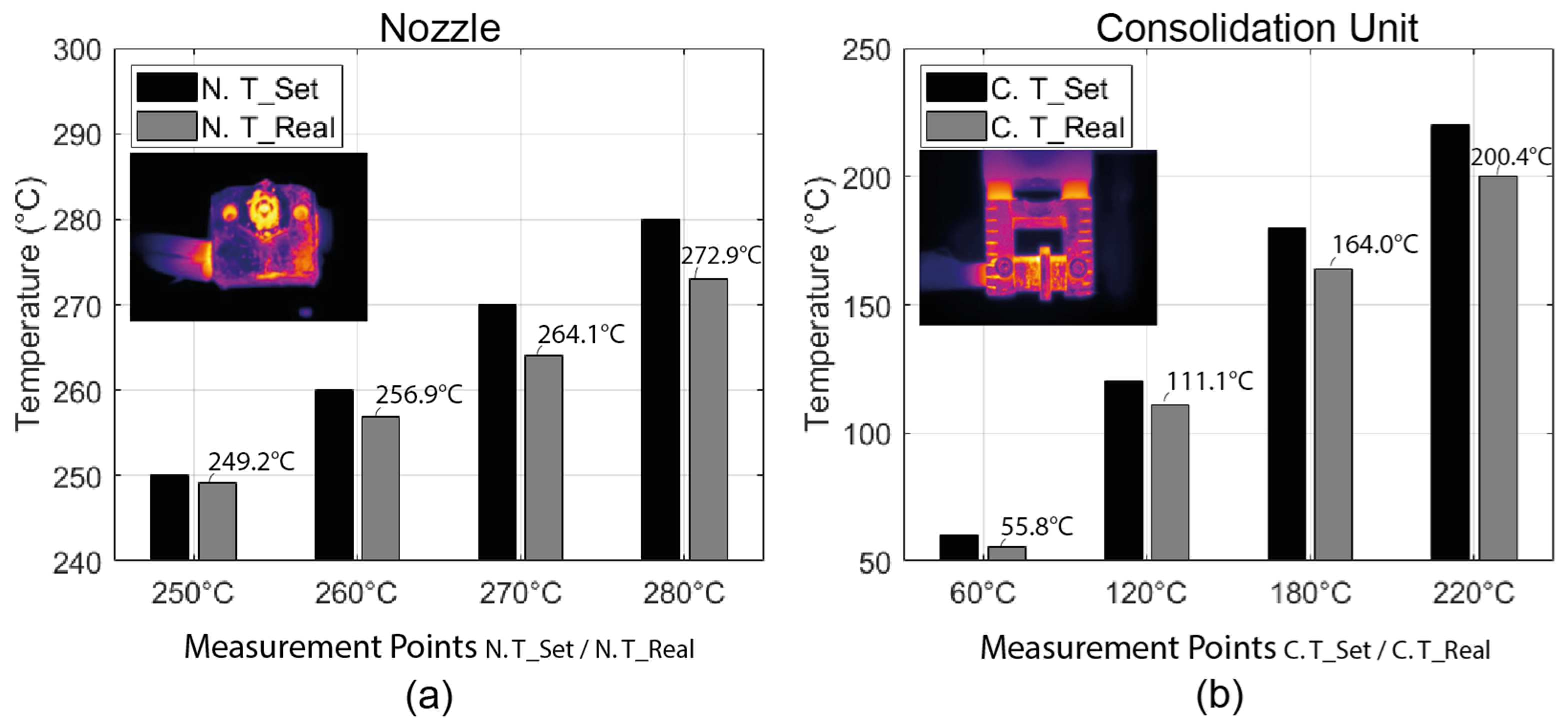
4.1.1. Temperature Control

To determine the actual temperatures at the 3D-printing nozzle and the TMIC roller, a thermistor sensor was used to measure directly at the test object. This sensor is controlled via the proportional–integral–derivative (PID) regulator of the controller board. However, since this measurement does not capture the exact temperature at the contact surface during the printing process, the temperature was additionally measured using the integrated infrared camera.
The infrared camera was positioned 100 mm away from the test object. For the measurement at the 3D-printing nozzle, the consolidation surface was captured. To achieve this, the hotend was dismounted from the print head base plate, rotated 90° in the sagittal plane, and fixed in a separate holder. Similarly, the TMIC roller was dismounted from the base plate and aligned 90° in the transverse plane toward the infrared camera to measure the contact surface. In the slicer software, the target temperature for the nozzle was set between 250 °C and 280 °C, and for the consolidation roller between 60 °C and 220 °C. The actual measurement results are represented by gray bars in Figure 10.

4.1.2. Consolidation Force

To ensure that the intended consolidation force is accurately applied over the roller’s contact area to the printed filament or the filament pre-consolidated by the nozzle, the load cell was calibrated, and its measurements were validated. The calibration process began with establishing a zero-load baseline. Subsequently, a series of known reference weights were incrementally applied. This was performed using a calibrated precision scale (see Figure 11a) by gradually lowering the Z-axis to systematically increase the applied force on the scale. A calibration curve was then developed (see Figure 11b) to quantify the relationship between the measured force and the corresponding output signal. The calibration was further validated under actual printing conditions, and the results were documented to confirm the precision and reliability of the load cell measurements.
To ensure the correct layer height h , during the consolidation process, the nozzle must be adjusted to the desired height for the respective consolidation force. First, the required force is applied to the TMIC roller. Subsequently, the nozzle height is precisely adjusted using a feeler gauge (level shim) and two adjustment screws (see Figure 11c).

4.1.3. Printing Speed
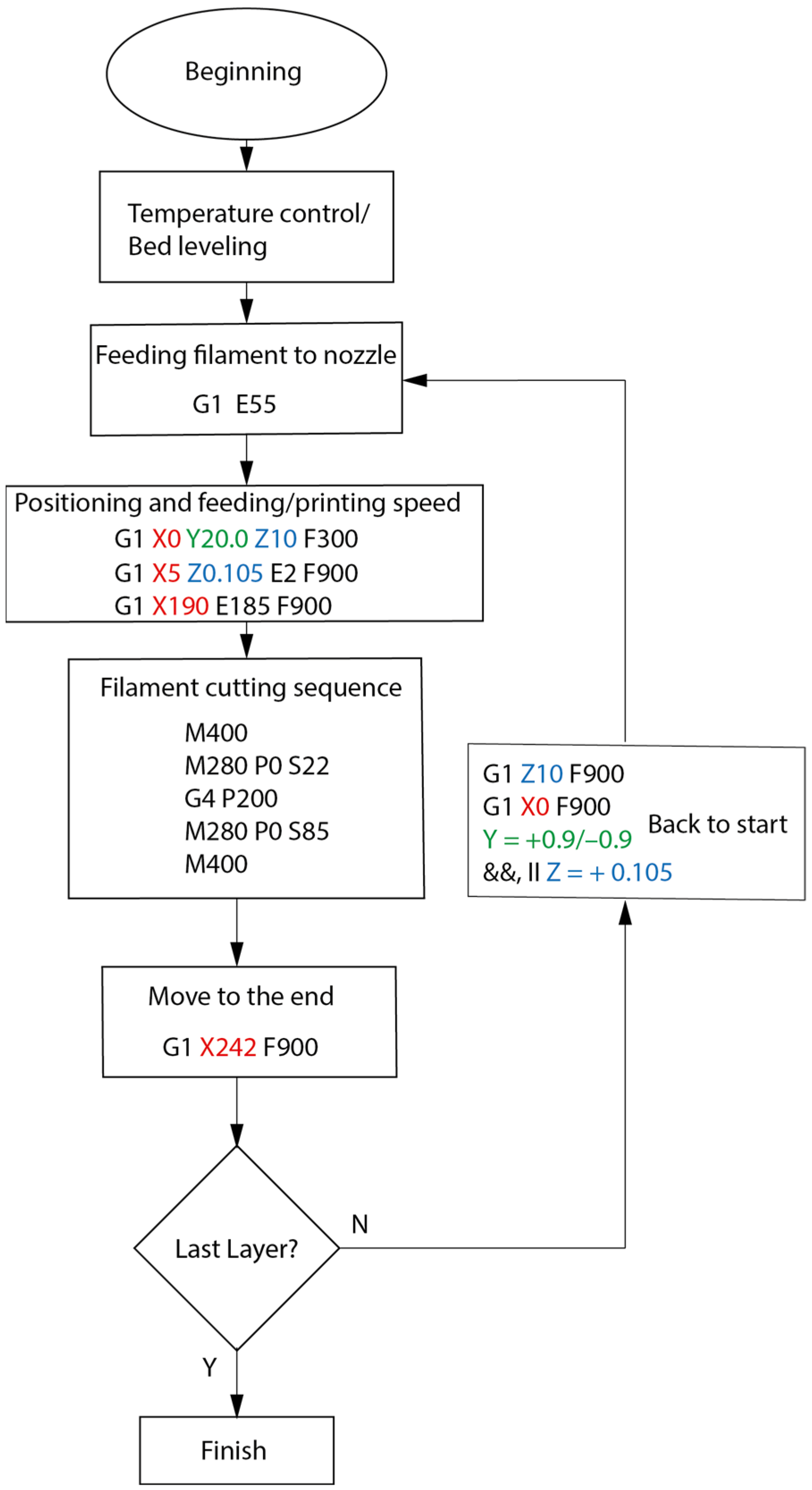
To ensure the consolidation process time, the X-axis speed was verified using the Voltcraft DT-20LK tachometer (Düsseldorf, North Rhine-Westphalia, Germany) and subsequently adjusted via the G-code print head speed. This step is necessary because specialized lead screws are used for the consolidation force, which differ from those found in conventional 3D printers.

4.2. Process Flow

The process for manufacturing TMIC CFRPC under controlled process parameters is governed by a self-developed G-code. It is critical to ensure that consistent process parameters are maintained within a defined range. The focus is solely on analyzing the effects of the process parameters on the material, without considering radii or print path orientation.

G-Code Generation

Figure 12 illustrates the flow diagram of the consolidation process for fabricating test specimens. Once the target temperature is reached, a precise measurement of the print bed is conducted at six reference points. Subsequently, the print head is moved to the starting position, and the filament is transported from the cutter unit to the preheated nozzle. The filament is then deposited onto the print bed by moving along the X-axis and lowering the Z-axis to the desired layer height. This process continues until the cutting sequence is initiated. During the cutting process, extrusion is paused for 200 ms to allow the filament to be severed. The remaining filament is then extracted from the print head through a forward motion of the print head. If the end of the printing process has not been reached, the procedure is continued by adjusting the Y-axis (sample width) or layer height accordingly. Figure 13 provides a schematic representation of the overall printing process, highlighting movements along the X- and Y-axes.

5. Experiments

5.1. Material

The filament used is a CFRPC with a CF and PA6 matrix supplied by Markforged Inc. Since the specific mechanical properties of the reinforcing CF, the PA6 matrix, and the fiber volume fraction were not provided by the manufacturer, a prior investigation was conducted to determine these characteristics. In a previous study [54], the melting and cold crystallization temperatures were analyzed in detail using differential scanning calorimetry (DSC). The results are presented in Table 3. Based on these results, particularly the material’s melting and crystallization temperatures, the process temperatures were defined.
During the fabrication process of the test specimens, the filament spool was stored in a sealed dry box containing silica gel packets to maintain the polymer’s moisture absorption at a minimal level. The temperature inside the box was consistently maintained at 40 °C. Additionally, the continuous fiber filament was pre-dried for 24 h at 50–60 °C before each printing cycle. Studies have shown that this conditioning method minimizes plasticization effects and enhances the material’s mechanical properties [55].

5.2. Methods

In the initial test run, test specimens were produced without a TMIC, using the standard process parameters provided by Markforged Inc., to establish a qualitative baseline for the subsequent optimization of process parameters. In the second run, specimens were fabricated without consolidation but with an optimized layer height of 0.105 mm, as described in [16]. This experimental run should demonstrate the effect of the reduced nozzle distance on the filament and also serves as a comparison to the TMIC samples. The consolidated process parameter set, also featuring an optimized layer height of 0.105 mm and a consolidation distance D x of 18 mm from the nozzle, was developed using a 2k full factorial design of experiments (DoE) with center points approach combined with a supplementary one factor at a time (OFAT) experimental series.
This paper focuses exclusively on the optimized consolidated parameter set, comparing it with the unconsolidated samples to highlight the impact of controlled consolidation on the laminate. The complete DoE analysis using the OFAT approach, along with cross-section analyses of all parameter sets, will be addressed in a separate, subsequent paper. The test specimens, process parameters, and testing equipment used are described in detail in the following sections.

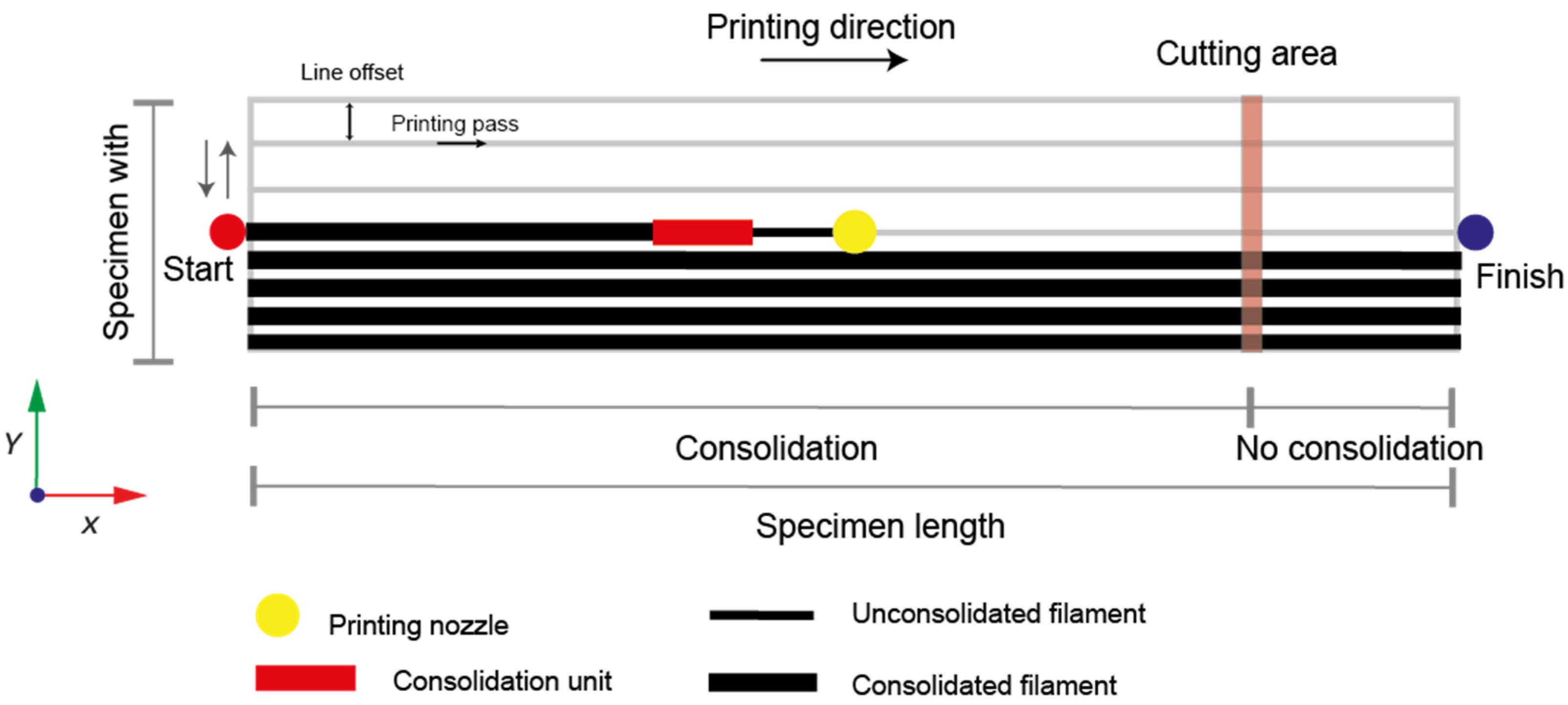
5.2.1. Specimen Conditions

To gain an initial understanding of the consolidation’s effect on the filament, single tracks for each configuration were printed and embedded for cross-sectional analysis. The material tests were conducted using three-point bending (3PB) tests. The specimen dimensions were 60 × 15 × 2 mm (length × width × thickness), in accordance with ISO 14125 testing standards [56], with a line offset of approximately 0.9 mm. The test rig produced three samples per parameter set, each with a width of 15 mm and a length of 242 mm. From these samples, series were fabricated within a single print job, depending on the configured process parameters. For each parameter set, a total of eight 3PB specimens with 0° fiber orientation were produced, along with one sample for micro-CT analysis and one for cross-sectional analysis (see Figure 14). The section of the continuous fiber filament following the cutting process was excluded from analysis and discarded, as this region was unsupported by the filament feeder and only partially consolidated to one-third of its intended level.

5.2.2. Printing Conditions

The printing speed of 15 mm/s, the actual nozzle temperature of 272 °C, and the print bed temperature of 30 °C were adopted from the standard Markforged settings to enable a qualitative comparison with commercially available 3D-printing technologies. Table 4 show the different printing conditions. The M F series was fabricated with the same layer height as Markforged and without consolidation, while the C 0 series was produced with an optimized layer height, also without consolidation. The C 1 series represents the optimized consolidated parameter set derived from the systematic experimental series using the 2 2 full factorial DoE with center points and OFAT methods.

5.2.3. Material Testing

The 3PB tests were conducted on a Zwick Roell multi-testing machine Z020 (Ulm, Germany). The manufacturer’s software testXpert II (Ulm, Germany) was used on the testing machine to initialize the test parameters and record the test data. The testing speed, the support spans and radii, as well as the load span radii, were adjusted according to the ISO 14125 testing standard to meet the specifications of the respective composite material.

5.2.4. Microscopy

The digital microscope Keyence VHX-7020 (Osaka, Japan) with a resolution about 100 to 1000 with the VH-Z100T universal zoom lens (Osaka, Japan) was used to observe the fiber distribution as well as the void content of the test specimens. The image and void content analysis were performed using Keyence’s analysis software VHX-H5M for VHX-7000 (Osaka, Japan).

5.2.5. Thermal Analysis

To gain an understanding of the thermal processes during printing and the influence of the TMIC unit near the bonding zone, thermographic video recordings of printed tracks with a layer height of 0.105 mm were created and analyzed. Only the C 0 and C 1 samples were investigated for this purpose. Single tracks were printed layer by layer, with recordings beginning at the 15th layer. This ensures that both samples experience identical conditions regarding heat conduction into the substrate. The measurements were conducted using the infrared camera described in Section 3.1.3. Measurement points were positioned between the printing nozzle and the consolidation roller to capture the resulting temperature gradient, which was subsequently analyzed using the IRSoft software.

6. Results and Discussion

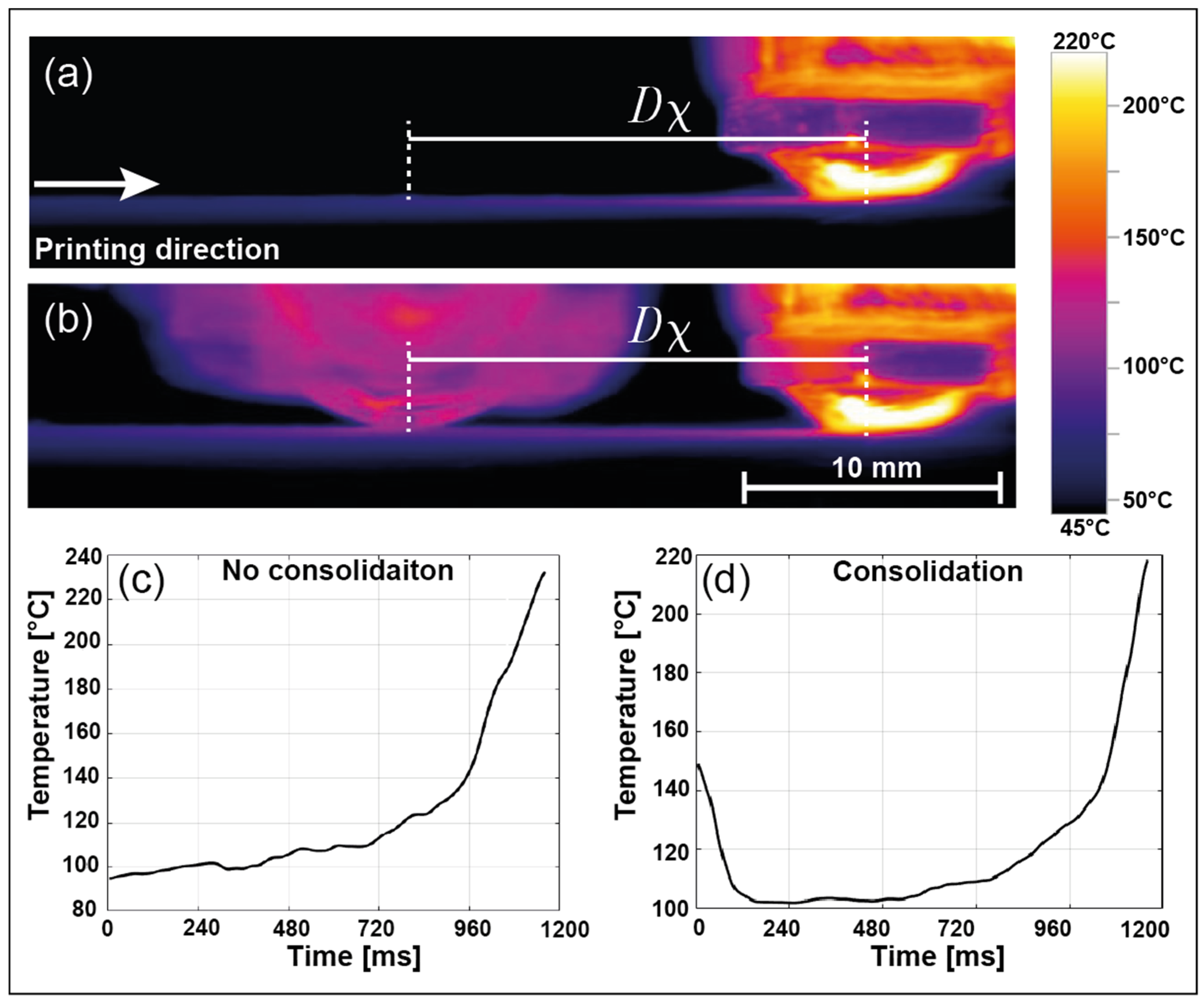
6.1. Cross-Section and Void Observation

Figure 15 presents cross-sectional images of the individual tracks for each configuration, oriented perpendicular to the fiber direction. It is evident that sample C 0 (see Figure 15a) shows a different sample geometry, fiber distribution, and void content compared to M F (see Figure 15c), which can be attributed to the reduced nozzle height. Sample C 0 exhibits a lower height and greater lateral deformation than the M F sample. By applying the layer height from sample (a) along with controlled TMIC, sample C 1 (see Figure 15b) was further compressed by 55 µm in height and widened by 92 µm on the print bed. The cross-sectional image reveals that the fibers are more evenly distributed within the matrix, and the void content has been further reduced.
Figure 16a–c show the cross-sectional samples of the laminates with 9 layers from each experimental setup, as outlined in Table 4. The blue areas represent the voids in the laminate, while the black dashed lines indicate the individual layers of the laminate. To evaluate the void content, three representative surface sections were selected from each sample. Each section was analyzed to determine the surface void content, and the arithmetic mean of the three results was calculated to obtain the final value (see Figure 16d).
The C 0 sample without consolidation (see Figure 16a) exhibits a small number of voids between layers, referred to as macrovoids. However, numerous smaller voids between fiber bundles, termed microvoids, are also visible. The consolidated laminate from C 1 (see Figure 16b) demonstrates a significantly lower content of both micro- and macro-voids, with fibers evenly distributed within the matrix. Hardly any layer transitions are discernible, indicating strong structural bonding between layers. The void content of the C 0 sample is 5.3%, whereas the C 1 sample shows a much lower void content of only 0.8% (see Figure 16e). For qualitative comparison, the M F sample produced using Markforged process parameters (see Figure 16c) exhibits a high proportion of both micro- and macrovoids, with a void content exceeding 9%, consistent with results reported in the literature for the Mark Two desktop printer [14].

6.2. Bending Test Results

This study demonstrates that TMIC significantly improved the mechanical properties of the material (see Figure 17). The baseline sample, C 0 , achieved a flexural strength of approximately 730 MPa and a bending modulus of 44 GPa. In comparison, the optimized TMIC sample, C 1 , exhibited a flexural strength of 1220 MPa and a bending modulus of 86 GPa, representing a 67% increase in flexural strength and a 100% increase in bending modulus. Additionally, the analysis revealed that the variability of C 1 was reduced by 41% compared to C 0 .
A qualitative comparison with the M F sample indicates that the optimized consolidation strategy improved the flexural strength by over 140% and the bending modulus by over 125%.
The mechanical investigation of the materials reveals a direct correlation between void content and fiber distribution. TMIC sample C 1 demonstrate improved mechanical properties compared to unconsolidated samples, C 0 and M F , due to the lower void content and more homogeneous fiber distribution, as shown in Figure 16a–c,e. The reduction in voids and the uniform fiber arrangement facilitate a more efficient load transfer within the matrix, thereby enhancing the mechanical performance of TMIC C 1 .

6.3. Thermal Analysis of the Printed CFRPC Filament

Figure 18 presents thermographic images alongside the corresponding temperature–time diagrams for the printing process without consolidation, using the process parameters of C 0 , and with consolidation, using the process parameters of C 1 . The measurements begin at the center of the nozzle and extend across the substrate surface to the point where the filament reaches the central axis of the consolidation unit. With a distance of 18 mm between the nozzle’s central axis and that of the TMIC unit, the time from fiber deposition to thermal consolidation is precisely 1200 ms at a printing speed of 15 mm/s. This duration serves as the reference time for the thermal measurements.
The temperature–time diagram without consolidation (see Figure 18c) shows that the temperature near the bonding zone drops rapidly after the nozzle, although temperatures between 200 °C and 180 °C are still present shortly behind the nozzle. This could lead to deconsolidation of the laminate.
In contrast, the temperature–time diagram with consolidation (see Figure 18d) indicates that applying the consolidation roller at 180 °C and 15 N causes the temperature near in the bonding zone to rise back to 149 °C. This temperature is close to the crystallization temperature of PA6, as determined by DSC, and supports both the reduction in deconsolidation effects and the diffusion healing process within the laminate. However, these temperature values should be interpreted with caution, as the temperature measurement was not taken directly in the bonding zone, and heat may have been quickly lost due to possible convection at the material surface.

7. Conclusions and Outlook

This study presented the development and validation of a test rig for consolidation in the -3D printing of CFRPC and demonstrates that targeted TMIC significantly enhances the quality and mechanical properties of these materials. Multiple developmental steps were required to achieve reproducible results. Special attention was given to the deformation of the entire structure under high consolidation forces on the roller’s contact area, as this could adversely affect the precise deposition of fibers through the nozzle, the layer height, and the pre-consolidation process. Additionally, material warping caused by high consolidation temperatures played a critical role, further impacting the accuracy of fiber placement. To address these challenges, structural reinforcements and appropriate thermal decoupling elements were incorporated at critical points in the design.
The positioning of sensors for process monitoring and the subsequent quality analysis of the printed components was also of paramount importance and was successfully optimized. After initial functionality tests and the validation of individual test rig components, a 2k full factorial DoE analysis was conducted to optimize laminate quality with CFRPC materials. In this study, only the optimized sample is compared with an unconsolidated sample. To enable a qualitative comparison and assess the impact of pre-consolidation on the laminate, an additional experimental series using process parameters from Markforged Inc. was conducted and summarized.
Cross-sectional analyses revealed that TMIC significantly reduced the void content, nearly eliminating it compared to unconsolidated samples. This led to a more uniform fiber distribution within the matrix and improved interlayer bonding. Thermal analysis confirmed that TMIC maintains a higher bonding zone temperature, which supports diffusion healing and reduces deconsolidation effects. The 3PB tests demonstrated that TMIC increased flexural strength by up to 67% and stiffness by up to 100%, highlighting the substantial improvement in mechanical performance. The results clearly show that controlled in situ consolidation not only reduces porosity but also enhances material homogeneity, structural integrity, and overall mechanical properties, making it a promising approach for CFRPC additive manufacturing.
The test rig offers further optimization potential for process parameters such as consolidation force, temperature profiles, and processing speed, which could improve the reproducibility and consistency of mechanical properties in AM composites for industrial applications. Additionally, expanding the investigation to include various matrix materials and fiber types could unlock new applications for the TMIC method. Moreover, existing consolidation models, such as those by Lee and Springer, Mantel and Springer, or Ranganathan, should be evaluated for their functionality and reproducibility in the context of consolidating 3D-printed CFRPC laminates using the applied technological approach. This would enable precise control of intimate contact and, consequently, void content through well-defined process parameters. A crucial next step is the development of a TMIC system capable of handling curved paths and radii, allowing for the fabrication of more complex geometries. This poses a challenge, especially for six-axis robotic printing, as pre-consolidation at melting temperature is essential for stable filament deposition but may limit design flexibility. Additionally, further optimization of the consolidation unit’s surface materials is required to ensure efficient heat transfer while preventing adhesion issues at higher temperatures. Future work could also integrate real-time monitoring systems that allow adaptive adjustments during the printing process, reducing post-processing efforts and improving the overall efficiency of composite manufacturing.
In the next study, the results of the 2k full factorial DoE will be statistically evaluated and presented alongside an OFAT analysis. A detailed material characterization using µ-CT analyses will focus on void reduction and fiber volume content behavior.

Author Contributions

Conceptualization, H.O. and M.L.; Data curation, H.O.; Investigation, H.O.; Formal analysis, H.O.; Methodology, H.O.; Visualization, H.O.; Supervision, S.T.A.-F.; Writing—original draft, H.O.; Writing—review and editing, H.O., M.L., G.H.M.d.O. and S.T.A.-F. All authors have read and agreed to the published version of the manuscript.

Funding

The authors would like to acknowledge the Open Access Funding by the Graz University of Technology.

Data Availability Statement

All data of this study are included within the manuscript. Raw data are available from the corresponding upon reasonable request.

Conflicts of Interest

The authors declare no conflicts of interest.

References

  1. Luk, J.M.; Kim, H.C.; DeKleine, R.D.; Wallington, T.J.; MacLean, H.L. Greenhouse gas emission benefits of vehicle lightweighting: Monte Carlo probabalistic analysis of the multi material lightweight vehicle glider. Transp. Res. Part D Transp. Environ. 2018, 62, 1–10. [Google Scholar] [CrossRef]
  2. OECD. The Next Production Revolution: Implications for Governments and Business; OECD Publishing: Paris, France, 2017; ISBN 9789264270992. [Google Scholar]
  3. Despeisse, M.; Baumers, M.; Brown, P.; Charnley, F.; Ford, S.J.; Garmulewicz, A.; Knowles, S.; Minshall, T.; Mortara, L.; Reed-Tsochas, F.P.; et al. Unlocking value for a circular economy through 3D printing: A research agenda. Technol. Forecast. Soc. Change 2017, 115, 75–84. [Google Scholar] [CrossRef]
  4. Berman, B. 3-D printing: The new industrial revolution. Bus. Horiz. 2012, 55, 155–162. [Google Scholar] [CrossRef]
  5. Verified Market Reports. Globaler Markt für 3D-Gedruckte Verbundwerkstoffe nach Typ (Kohlefaser, Glasfaser), nach Anwendung (Luft- und Raumfahrt und Verteidigung, Transport), nach geografischem Umfang und Prognose. Available online: https://www.verifiedmarketreports.com/de/product/global-3d-printed-composites-market-2019-by-manufacturers-regions-type-and-application-forecast-to-2024/ (accessed on 14 December 2024).
  6. Stratview Research. 3-Printed-Composites-Market Size, Share, Trend, Forecast & Industry Analysis: 2019–2024. Available online: https://www.stratviewresearch.com/271/3D-Printed-Composites-Market.html (accessed on 22 November 2024).
  7. Mason, H.; Gardiner, G. 3D Printing with Continuous Fiber: A Landscape. Available online: https://www.compositesworld.com/articles/3d-printing-with-continuous-fiber-a-landscape (accessed on 1 August 2023).
  8. Blok, L.G.; Longana, M.L.; Yu, H.; Woods, B. An investigation into 3D printing of fibre reinforced thermoplastic composites. Addit. Manuf. 2018, 22, 176–186. [Google Scholar] [CrossRef]
  9. Tian, X.; Todoroki, A.; Liu, T.; Wu, L.; Hou, Z.; Ueda, M.; Hirano, Y.; Matsuzaki, R.; Mizukami, K.; Iizuka, K.; et al. 3D Printing of Continuous Fiber Reinforced Polymer Composites: Development, Application, and Prospective. Chin. J. Mech. Eng. Addit. Manuf. Front. 2022, 1, 100016. [Google Scholar] [CrossRef]
  10. Saeed, K.; McIlhagger, A.; Harkin-Jones, E.; McGarrigle, C.; Dixon, D.; Ali Shar, M.; McMillan, A.; Archer, E. Characterization of continuous carbon fibre reinforced 3D printed polymer composites with varying fibre volume fractions. Compos. Struct. 2022, 282, 115033. [Google Scholar] [CrossRef]
  11. Becker, C.; Oberlercher, H.; Heim, R.B.; Wuzella, G.; Faller, L.M.; Riemelmoser, F.O.; Nicolay, P.; Druesne, F. Experimental Quantification of the Variability of Mechanical Properties in 3D Printed Continuous Fiber Composites. Appl. Sci. 2021, 11, 11315. [Google Scholar] [CrossRef]
  12. Zhilyaev, I.; Grieder, S.; Küng, M.; Brauner, C.; Akermann, M.; Bosshard, J.; Inderkum, P.; Francisco, J.; Eichenhofer, M. Experimental and numerical analysis of the consolidation process for additive manufactured continuous carbon fiber-reinforced polyamide 12 composites. Front. Mater. 2022, 9, 8–12. [Google Scholar] [CrossRef]
  13. 9T Labs AG. Available online: https://www.9tlabs.com/ (accessed on 2 December 2024).
  14. Ueda, M.; Kishimoto, S.; Yamawaki, M.; Matsuzaki, R.; Todoroki, A.; Hirano, Y.; Le Duigou, A. 3D compaction printing of a continuous carbon fiber reinforced thermoplastic. Compos. Part A Appl. Sci. Manuf. 2020, 137, 105985. [Google Scholar] [CrossRef]
  15. Henninger, F.; Ye, L.; Friedrich, K. Deconsolidation behaviour of glass fibre-polyamide 12 composite sheet material during post-processing. Plast. Rubber Compos. Process. Appl. 1998, 27, 287–292. [Google Scholar]
  16. Oberlercher, H.; Heim, R.B.; Laux, M.; Berndt, A.; Becker, C.; Amancio-Filho, S.T.; Riemelmoser, F.O. Additive manufacturing of continuous carbon fiber reinforced polyamide 6: The effect of process parameters on the microstructure and mechanical properties. Procedia Struct. Integr. 2021, 34, 111–120. [Google Scholar] [CrossRef]
  17. Stokes-Griffin, C.M.; Matuszyk, T.I.; Compston, P.; Cardew-Hall, M.J. Modelling the Automated Tape Placement of Thermoplastic Composites with In-Situ Consolidation. In Sustainable Automotive Technologies 2012; Subic, A., Wellnitz, J., Leary, M., Koopmans, L., Eds.; Springer: Berlin/Heidelberg, Germany, 2012; pp. 61–68. ISBN 978-3-642-24144-4. [Google Scholar]
  18. Mazumdar, S.K.; Hoa, S.V. Application of Taguchi method for process enhancement of on-line consolidation technique. Composites 1995, 26, 669–673. [Google Scholar] [CrossRef]
  19. Rosselli, F.; Santare, M.H.; Güçeri, S.I. Effects of processing on laser assisted thermoplastic tape consolidation. Compos. Part A Appl. Sci. Manuf. 1997, 28, 1023–1033. [Google Scholar] [CrossRef]
  20. Esche, R.v.d. Herstellung Langfaserverstärkter Thermoplastbauteile unter Zuhilfenahme von Hochleistungslasern als Wärmequelle; Zugl.: Aachen, Techn. Hochsch., Diss., 2001; Shaker: Aachen, Germany, 2001; ISBN 3-8265-9171-2. [Google Scholar]
  21. Brogan, M.T.; Monaghan, P.F. Thermal simulation of quartz tube infra-red heaters used in the processing of thermoplastic composites. Compos. Part A Appl. Sci. Manuf. 1996, 27, 301–306. [Google Scholar] [CrossRef]
  22. Haupert, F. Thermoplast-Wickeltechnik: Einfluß der Verarbeitungstechnologie auf Struktur und Eigenschaften Kontinuierlich Faserverstärkter Verbundwerkstoffe; Zugl.: Kaiserslautern, Univ., Diss, Als Ms. gedr; VDI-Verl.: Düsseldorf, Germany, 1997; ISBN 3183435020. [Google Scholar]
  23. Mazumdar, S. Composites Manufacturing; CRC Press: Boca Raton, FL, USA, 2001; ISBN 9780429127427. [Google Scholar]
  24. Advanced Composites Manufacturing; Gutowski, T.G.P., Ed.; John Wiley & Sons Inc: New York, NY, USA; Chichester, UK; Weinheim, Germany; Brisbane, Australia; Singapore; Toronto, ON, Canada, 1997; ISBN 978-0-471-15301-6. [Google Scholar]
  25. Khan, M.A. Experimental and Simulative Description of the Thermoplastic Tape Placement Process with Online Consolidation; Zugl.: Kaiserslautern, Techn. Univ., Diss., 2010, Als Ms. gedr; Inst. für Verbundwerkstoffe: Kaiserslautern, Germany, 2010; ISBN 978-3-934930-90-2. [Google Scholar]
  26. Kunststoffchemie für Ingenienure; Wolfgang, K., Ed.; 3 Auflage; Carl Hanser Verlag GmbH & Co. KG: Munich, Germany, 2011; ISBN 978-3-446-43047-1. [Google Scholar]
  27. Mantell, S.C.; Springer, G.S. Manufacturing Process Models for Thermoplastic Composites. J. Compos. Mater. 1992, 26, 2348–2377. [Google Scholar] [CrossRef]
  28. Ranganathan, S.; Advani, S.G.; Lamontia, M.A. A Non-Isothermal Process Model for Consolidation and Void Reduction during In-Situ Tow Placement of Thermoplastic Composites. J. Compos. Mater. 1995, 29, 1040–1062. [Google Scholar] [CrossRef]
  29. Pitchumani, R.; Gillespie, J.W.; Lamontia, M.A. Design and Optimization of a Thermoplastic Tow-Placement Process with In-Situ Consolidation. J. Compos. Mater. 1997, 31, 244–275. [Google Scholar] [CrossRef]
  30. Lee, W.; Springer, G.S. A Model of the Manufacturing Process of Thermoplastic Matrix Composites. J. Compos. Mater. 1987, 21, 1017–1055. [Google Scholar] [CrossRef]
  31. Loos, A.C.; Dara, P.H. Processing of Thermoplastic Matrix Composites. In Review of Progress in Quantitative Nondestructive Evaluation; Springer Nature: Berlin/Heidelberg, Germany, 1987; Volume 6A, ISBN 978-1-4612-9054-4. [Google Scholar]
  32. Schürmann, H. Konstruieren mit Faser-Kunststoff-Verbunden: Mit 39 Tabellen; 2., bearb. und erw. Aufl.; Springer: Berlin/Heidelberg, Germany, 2007; ISBN 978-3-540-72189-5. [Google Scholar]
  33. Lupone, F.; Padovano, E.; Venezia, C.; Badini, C. Experimental Characterization and Modeling of 3D Printed Continuous Carbon Fibers Composites with Different Fiber Orientation Produced by FFF Process. Polymers 2022, 14, 426. [Google Scholar] [CrossRef]
  34. Iragi, M.; Pascual-González, C.; Esnaola, A.; Lopes, C.S.; Aretxabaleta, L. Ply and interlaminar behaviours of 3D printed continuous carbon fibre-reinforced thermoplastic laminates; effects of processing conditions and microstructure. Addit. Manuf. 2019, 30, 100884. [Google Scholar] [CrossRef]
  35. Chen, S.; Cai, L.; Duan, Y.; Jing, X.; Zhang, C.; Xie, F. Performance enhancement of 3D-printed carbon fiber-reinforced nylon 6 composites. Polym. Compos. 2024, 45, 5754–5772. [Google Scholar] [CrossRef]
  36. Wagmare, R.; Harshe, R.; Pednekar, J.; Patro, T.U. Additive manufacturing of continuous fiber-reinforced polymer composites: Current trend and future directions. Prog. Addit. Manuf. 2024, 9, 1–28. [Google Scholar] [CrossRef]
  37. Zhang, H.; Chen, J.; Yang, D. Fibre misalignment and breakage in 3D printing of continuous carbon fibre reinforced thermoplastic composites. Addit. Manuf. 2021, 38, 101775. [Google Scholar] [CrossRef]
  38. Yudhanto, A.; Aldhirgham, A.; Feron, E.; Lubineau, G. Post-consolidation process for modifying microscale and mesoscale parameters of 3D printed composite materials. Front. Mater. 2023, 10, 1286840. [Google Scholar] [CrossRef]
  39. Wu, H.; Chen, X.; Xu, S.; Zhao, T. Evolution of Manufacturing Defects of 3D-Printed Thermoplastic Composites with Processing Parameters: A Micro-CT Analysis. Materials 2023, 16, 6521. [Google Scholar] [CrossRef] [PubMed]
  40. Todoroki, A.; Oasada, T.; Mizutani, Y.; Suzuki, Y.; Ueda, M.; Matsuzaki, R.; Hirano, Y. Tensile property evaluations of 3D printed continuous carbon fiber reinforced thermoplastic composites. Adv. Compos. Mater. 2020, 29, 147–162. [Google Scholar] [CrossRef]
  41. Heim, R.B. Mikrostrukturelle Analyse Eines Additiv Gefertigten Endlosfaserverbundwerkstoffes. Bachelor’s Thesis, CarinthiaUniversity of Applied Sciences, Villach, Austria, 2020. [Google Scholar]
  42. Ye, L.; Chen, Z.-R.; Lu, M.; Hou, M. De-consolidation and re-consolidation in CF/PPS thermoplastic matrix composites. Compos. Part A Appl. Sci. Manuf. 2005, 36, 915–922. [Google Scholar] [CrossRef]
  43. Struzziero, G.; Barbezat, M.; Skordos, A.A. Consolidation of continuous fibre reinforced composites in additive processes: A review. Addit. Manuf. 2021, 48, 102458. [Google Scholar] [CrossRef]
  44. Guglhör, T. Experimentelle und Modellhafte Betrachtung des Konsolidierungsprozesses von Carbonfaserverstärktem Polyamid-6; Universität Augsburg: Augsburg, Germany, 2017. [Google Scholar]
  45. Amedewovo, L.; Orgéas, L.; Du Parscau Plessix, B.D.; Lefevre, N.; Levy, A.; Le Corre, S. Deconsolidation of carbon fiber-reinforced PEKK laminates: 3D real-time in situ observation with synchrotron X-ray microtomography. Compos. Part A Appl. Sci. Manuf. 2024, 177, 107917. [Google Scholar] [CrossRef]
  46. Michalec, P.; Laux, M.; Srinivas, G.L.; Weidner, R.; Brandstötter, M. Five-Axis Printing of Continuous Fibers on the Mold. JMMP 2025, 9, 17. [Google Scholar] [CrossRef]
  47. Elderfield, N.; Wong, J.C. Discrete in-situ consolidation of additively manufactured continuous fiber-reinforced polymer composites. Compos. Part A Appl. Sci. Manuf. 2023, 171, 107562. [Google Scholar] [CrossRef]
  48. He, Q.; Wang, H.; Fu, K.; Ye, L. 3D printed continuous CF/PA6 composites: Effect of microscopic voids on mechanical performance. Compos. Sci. Technol. 2020, 191, 108077. [Google Scholar] [CrossRef]
  49. Ouyang, Z.; Yang, L.; Pi, Z.; Wang, Z.; Yan, C.; Shi, Y. Robot-assisted laser additive manufacturing for high-strength/low-porosity continuous fiber-reinforced thermoplastic composites. Compos. Sci. Technol. 2024, 247, 110397. [Google Scholar] [CrossRef]
  50. Tu, Y.; Tan, Y.; Zhang, F.; Zou, S.; Zhang, J. High-Throughput Additive Manufacturing of Continuous Carbon Fiber-Reinforced Plastic by Multifilament. Polymers 2024, 16, 704. [Google Scholar] [CrossRef]
  51. Sieberer, S.; Savandaiah, C.; Pichler, S.; Maurer, J.; Schagerl, M. Influence of post-consolidation on continuous carbon-fibre reinforced additively manufactured specimens in bending. Compos. Struct. 2023, 320, 117176. [Google Scholar] [CrossRef]
  52. Zhang, J.; Zhou, Z.; Zhang, F.; Tan, Y.; Tu, Y.; Yang, B. Performance of 3D-Printed Continuous-Carbon-Fiber-Reinforced Plastics with Pressure. Materials 2020, 13, 471. [Google Scholar] [CrossRef]
  53. Savandaiah, C.; Sieberer, S.; Plank, B.; Maurer, J.; Steinbichler, G.; Sapkota, J. Influence of Rapid Consolidation on Co-Extruded Additively Manufactured Composites. Polymers 2022, 14, 1838. [Google Scholar] [CrossRef]
  54. Oberlercher, H.; Laux, M.; Heim, R.B.; Berndt, A.; Amancio-Filho, S.T.; Riemelmoser, F.O. In-situ consolidation of additively manufactured continuous fiber reinforced material: Technical approach and results. In Material Forming; Materials Research Forum LLC: Millersville, PA, USA, 2023; pp. 85–92. [Google Scholar]
  55. Banjo, A.D.; Agrawal, V.; Auad, M.L.; Celestine, A.-D.N. Moisture-induced changes in the mechanical behavior of 3D printed polymers. Compos. Part C Open Access 2022, 7, 100243. [Google Scholar] [CrossRef]
  56. DIN EN ISO 14125:2011-05; Fibre-reinforced plastic composites—Determination of flexural properties (ISO 14125:1998 + Cor.1:2001 + Amd.1:2011); German version EN ISO 14125:1998 + AC:2002 + A1:2011. DIN Media GmbH: Berlin, Germany, 2024.
Figure 1. The temperature and pressure profile during the processing of semi-crystalline thermoplastic fiber composites, along with the molecular penetration and consolidation mechanisms driven by the diffusion of polymer chains, as illustrated from (ad).
Jcs 09 00128 g001
Figure 2. Principles of the thermoplastic taping process with in situ consolidation.
Jcs 09 00128 g002
Figure 3. Two different 3D printing extrusion processes for CFRPC printing. (a) represents a co-extrusion process, where the polymer is melted and combined with continuous fibers directly within the nozzle before deposition; (b) shows a process using Prepreg fibers, where the fibers are already coated with the polymer matrix.
Jcs 09 00128 g003
Figure 4. (a) Nozzle design with PTFE isolation to prevent premature matrix melting in CFRPC 3D printing. (b) Shows the microscopic view of the consolidation area of a Markforged nozzle. (c) Illustrates the dimensions of the consolidation surface and the corresponding exit radius of the filament from the nozzle in cross-section.
Jcs 09 00128 g004
Figure 5. Microscopy of Markforged Inc. filament cross-section (a) and a laminate printed with a Mark Two printer (b).
Jcs 09 00128 g005
Figure 6. Schematic representation of the effects of the applied force F K and reduced layer height: (a) shows how the force F K reduces the layer height, (b) illustrates the filament being flattened in width by F K , and (c) shows the mechanical stress v ( z ) arising between the nozzle and the filament, potentially damaging reinforcement fibers.
Jcs 09 00128 g006
Figure 7. The basic structure of the TMIC test rig with its reinforced frame construction, the drives for the axes in the X, Y, and Z directions, and the enclosure of the entire test stand. (a) aluminum profile, (b) stepper motors, (c) glass plate, (d) trapezoidal spindle in the z-direction, (e) linear axis, (f) polymethylmethacrylate plates, (g) trapezoidal spindle in the X and Y-directions.
Jcs 09 00128 g007
Figure 8. Schematic representation of the TMIC print head with the applied consolidation forces on the CFRPC material. (a) filament feeder, (b) aluminum carrier plate, (c) damping unit, (d) Print head fans, (e) load cell, (f) filament cutter, (g) leveling sensor, (h) hotend, (i) TMIC roller and (j) print bed.
Jcs 09 00128 g008
Figure 9. Overview of the sensors installed in the consolidation test rig: (a) the side view and (b) the front view of the test rig.
Jcs 09 00128 g009
Figure 10. Temperature reference measurements for the 3D-printing nozzle and the TMIC unit: (a) illustrates the nozzle tip temperature, and (b) shows the surface temperature of the TMIC unit. In both cases, the black bars represent the target temperatures, while the gray bars indicate the actual measured temperatures.
Jcs 09 00128 g010
Figure 11. (a) Calibration of the consolidation force using a precision scale, showing a measurement of 5.07 N. (b) Calibration curve validating the load cell’s accuracy. (c) Nozzle height adjustment using a feeler gauge and adjustment screws to ensure correct layer height under the applied force.
Jcs 09 00128 g011
Figure 12. Flowchart of the consolidation process for the fabrication of test specimens.
Jcs 09 00128 g012
Figure 13. Schematic process flow of the entire printing process along the X- and Y-axes of the consolidation test rig.
Jcs 09 00128 g013
Figure 14. Schematic representation and overview of the extracted test samples from a test series.
Jcs 09 00128 g014
Figure 15. Cross-sectional images of CFRPC laminate samples with different process parameters—(a) C 0 , (b) C 1 , and (c) M F —showing the individual paths perpendicular to the fiber direction.
Jcs 09 00128 g015
Figure 16. Cross-sectional micrographs of CFRPC laminate samples processed under different conditions: (a) C 0 , (b) C 1 , and (c) M F . The blue areas represent voids in the laminate structure. The bar chart (e) compares the quantified void content for each sample, based on three representative regions (red squares on (d)), demonstrating the influence of different process parameters on consolidation quality.
Jcs 09 00128 g016
Figure 17. Presentation of the ultimate bending strength and bending modulus for different consolidation conditions of the CFRPC laminates: C 0 , C 1 , and M F .
Jcs 09 00128 g017
Figure 18. Thermographic images and temperature–time diagrams (a,c) for printing without consolidation (C₀) and (b,d) with consolidation (C₁). Without consolidation, the bonding zone temperature drops to approximately 90 °C, over a distance of D x 18 mm. With consolidation at 180 °C and 15 N, the temperature rises to 149 °C.
Jcs 09 00128 g018
Table 1. Overview of adjustable process parameters for the consolidation test rig for CFRPC with PA6 Matrix.
Process ParameterRange for PA6
Nozzle   temperature   ( T n ) 250–280 °C
Printing   bed   temperature   ( T b e d ) 30–80 °C
Consolidation   temperature   ( T C ) 60–220 °C
Nozzle   layer   height   ( h ) 0.105–0.125 mm
Consolidation   force   ( F C ) 0–30 N
Printing   speed   ( v ) 5–15 mm/s
Consolidation   distance   ( D x ) 10–25 m
Table 2. Sensors of consolidation test bench with specifications.
SensorsSpecification
Load cellHBM PW4M (Darmstadt, Germany)
Temperature sensorPT100 (Kleinostheim, Germany)
Thermistors104NT (Tokyo, Japan)
Infrared cameraTesto 890 (Titisee-Neustadt, Germany)
Bed levelingBLTouch V3.1 (Songpa-gu, Seoul, Republic of Korea)
Humidity sensorTesto Hygrometer (Titisee-Neustadt, Germany)
Table 3. Results of DSC measurement.
SampleGlass Transition Temperature [°C]Crystallization Temperature [°C]Melting Temperature [°C]
CF/PA666169225
PA654152242
Table 4. Printing conditions.
Condition h   [ m m ] v   [ m m / s ] T b e d   [ ] T N   [ ] D x   [ ] T C   [ ] F C   [ N ]
C 0 0.1051530272
C 1 1818015
M F 0.125
Disclaimer/Publisher’s Note: The statements, opinions and data contained in all publications are solely those of the individual author(s) and contributor(s) and not of MDPI and/or the editor(s). MDPI and/or the editor(s) disclaim responsibility for any injury to people or property resulting from any ideas, methods, instructions or products referred to in the content.

