
Polymer Nanocomposite Ablatives—Part III


Abstract
1. Introduction
2. Resin Matrix and Reinforcement Systems
2.1. Phenolic Resins as Matrix Resin
2.2. EPDM Rubber
2.3. New Thermosetting Resins
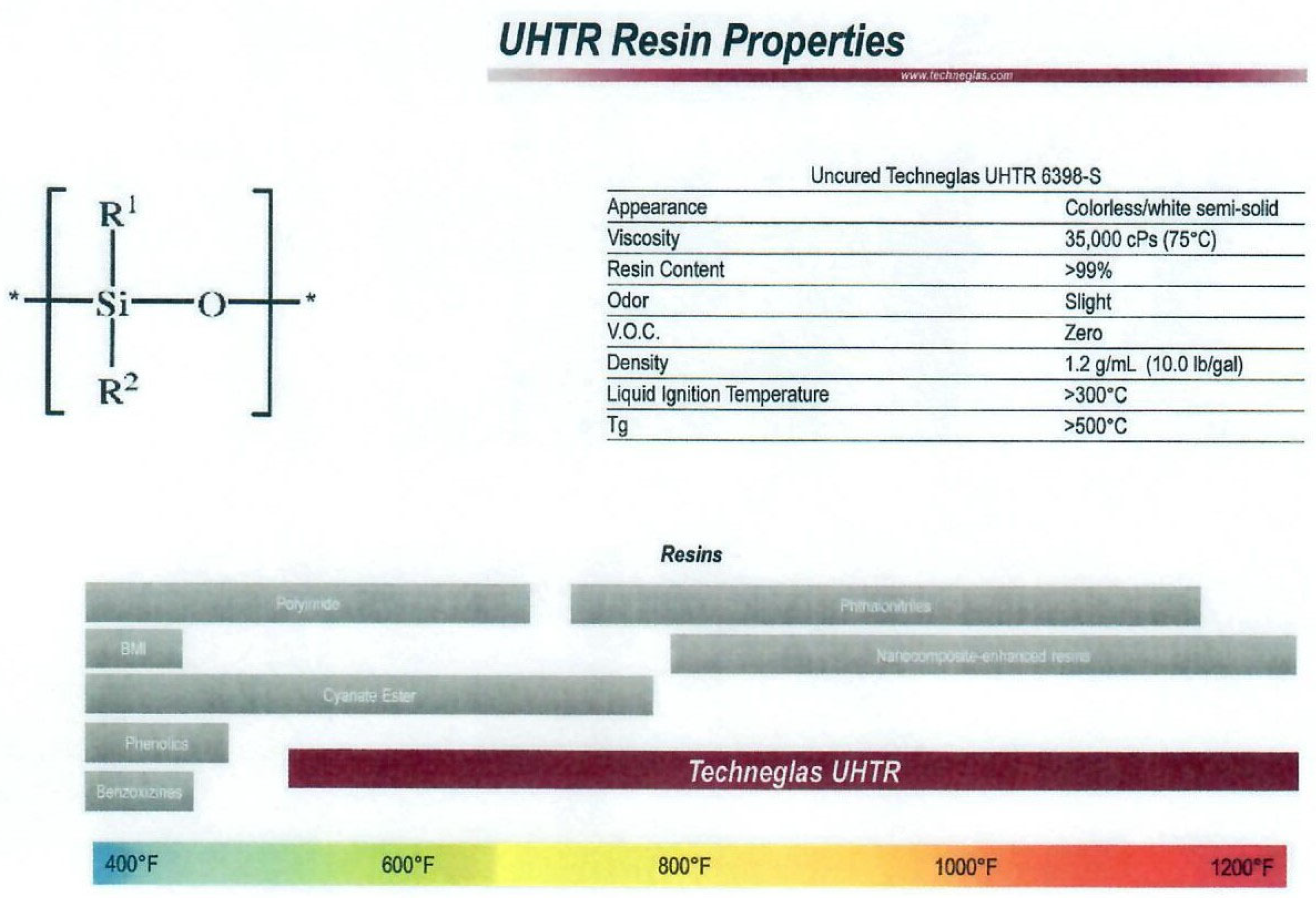
2.3.1. Polysiloxane
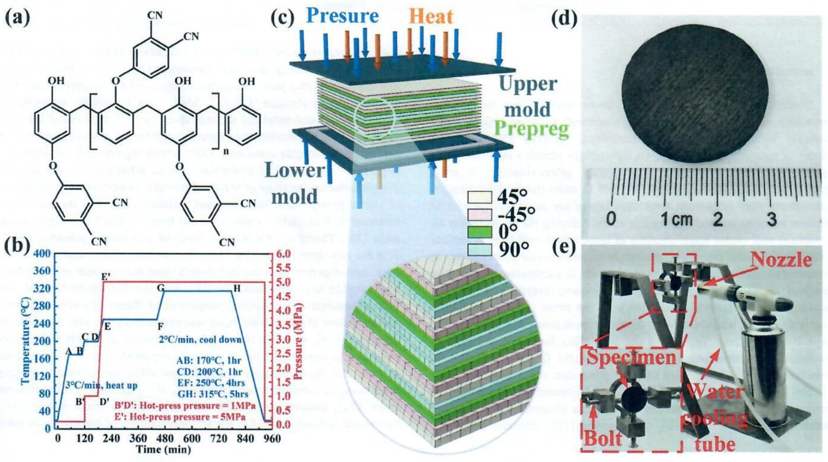
2.3.2. Phthalonitrile
3. Phenolic Resins–Transformation into Aerogel
3.1. Phenolic Silica Hybrid Aerogels
3.2. Phenolic Silicon Interpenetrating Aerogels
3.3. Phenolic Aerogel Without Reinforcement
4. Carbon Aerogel
4.1. Carbon Aerogels–No Reinforcement
4.2. Carbon Aerogels–Reinforcement
5. New Applications
5.1. Infrastructures
5.2. Ballistics
6. Summary and Concluding Remarks
Author Contributions
Funding
Data Availability Statement
Acknowledgments
Conflicts of Interest
References
- Koo, J.H.; Natali, M.; Tate, J.; Allcorn, E. Polymer Nanocomposites as Ablative Materials-A Comprehensive Review. Int. J. Energetic Mater. Chem. Propuls. 2013, 12, 119–162. [Google Scholar]
- Koo, J.H.; Pilato, L.A. Polymer Nanocomposite Ablatives—Part II. Int. J. Energetic Mater. Chem. Propuls. 2020, 19, 125–187. [Google Scholar]
- Jin, R.; Zhou, Z.; Liu, J.; Shi, B.; Zhou, N.; Wang, X.; Jia, X.; Guo, D.; Xu, B. Aerogels for Thermal Protection and Their Application in Aerospace. Gels 2023, 9, 606. [Google Scholar] [CrossRef] [PubMed]
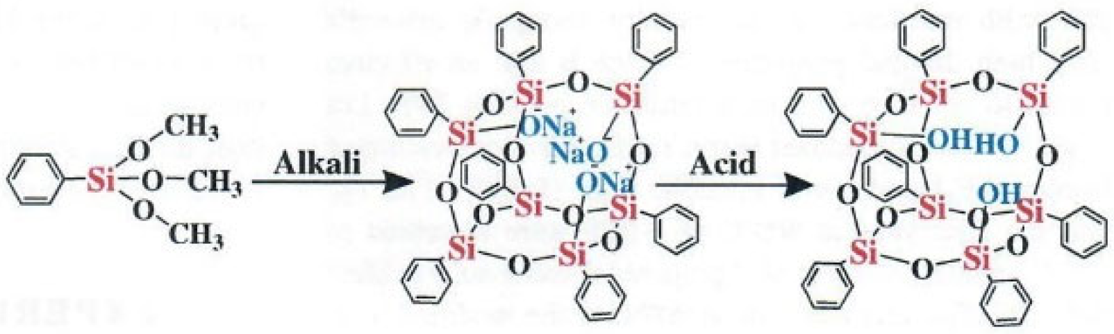
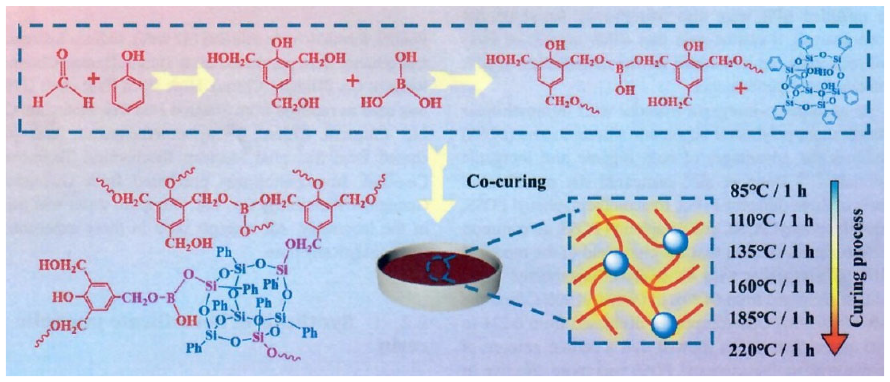
- Niu, Z.; Li, G.; Xin, Y.; Ma, X.; Zhang, C.; Hou, X. Enhanced thermal and anti-ablation properties of high-temperature resistant reactive POSS modified boron phenolic resin. J. Appl. Polym. Sci. 2022, 139, 52087. [Google Scholar] [CrossRef]
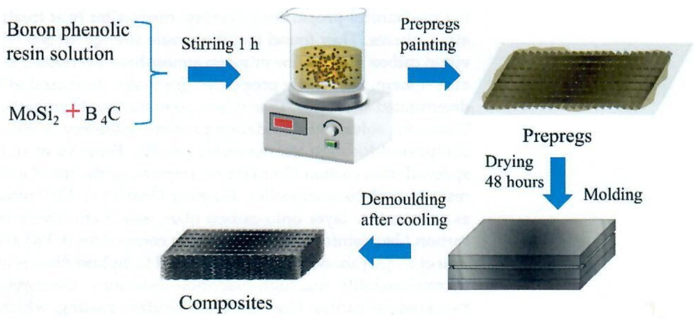
- Yang, T.; Dong, C.; Rong, Y.; Deng, Z.; Li, P.; Han, P.; Shi, M.; Huang, Z. Oxidation Behavior of Carbon Fibers in Ceramizable Phenolic Resin Matrix Composites at Elevated Temperatures. Polymers 2022, 14, 2785. [Google Scholar] [CrossRef] [PubMed]
- Li, L.; Li, Y.; Huan, D.; Chen, X.; Liu, H.; Wang, W.; Li, Y.; Jin, Y.; Li, W. Z-pin effect on interlaminar mechanical and ablation performance of quartz-phenolic composites. Polym. Compos. 2022, 43, 3228–3241. [Google Scholar] [CrossRef]
- Xi, K.; Li, J.; Wang, Y.; Guo, M.; Li, K. Thermal insulation and char layer mechanical properties of a novel ethylene propylene diene monomer composite reinforced with carbon nanotubes coated via chemical vapour deposition. Compos. Sci. Technol. 2021, 201, 108537. [Google Scholar]
- Guo, M.; Du, J.; Zhang, Y. Effect of CNT content and size on the high-temperature particle-erosion resistance of ablative materials for thermal protection systems. Compos. Sci. Technol. 2023, 235, 109969. [Google Scholar] [CrossRef]
- Koo, J.H. Char Yield Data of Seveal Commercially Available High-Termperature Resins; Unpublished Data; KAI, LLC: Austin, TX, USA, 2025. [Google Scholar]
- PICA Material Property Report; NASA Report C-TPSA-A-DOC-158, 8 June 2009, Revision: 1; NASA: Washington, DC, USA, 2009.
- Fish, C. High Performance Compositions and Composites. U.S. Patent 10,259,972, 16 April 2019. [Google Scholar]
- Fish, C. High Performance Compositions and Composites. U.S. Patent 10,538,685, 21 January 2020. [Google Scholar]
- Buffy, J. Techneglas UHTR Presentation to Northrup Grumman Corp; Publisher: Promontory, UT, USA, 2022. [Google Scholar]
- Hou, Y.; Yee, C.; Li, W.; Koo, J.H.; Li, L.; Rech, B.; Fahy, W.; Wu, H.; Buffy, J.J. A novel ablative material for thermal protection system: Carbon fiber/polysiloxane composites. Aerosp. Sci. Technol. 2022, 129, 107822. [Google Scholar]
- Koo, J.; Bernstein, S.; Pilato, L. A Novel Approach to Investigate Thermal Protection Systems Materials. Sampe J. 2024, 60, 26. [Google Scholar] [CrossRef]
- Yee, C.M.K. Development, Manufacturing, Characterization, and Modeling of a Novel Alumina/Polysiloxane/Boron Carbide Ablative Composite. Doctoral Dissertation, The University of Texas at Austin, Austin, TX, USA, 2024. [Google Scholar]
- LBNL. Advanced Light Source Beamline 8.3.2 Tomography. Available online: https://als.lbl.gov/beamlines/8-3-2/ (accessed on 27 July 2024).
- Keller, T.M.; Price, T.R. Amine-cured bisphenol-linked phthalonitrile resins. J. Macromol. Sci.—Chem. 1982, 18, 931–937. [Google Scholar]
- Keller, T.; Price, T. Polymerization of polysulphone phthalonitriles. Polym. Commun. 1985, 26, 48–50. [Google Scholar]
- Keller, T.M. Phthalonitrile-based high temperature resin. J. Polym. Sci. Part A Polym. Chem. 1988, 26, 3199–3212. [Google Scholar]
- Zhou, H.; Badashah, A.; Luo, Z.; Liu, F.; Zhao, T. Preparation and property comparison of ortho, meta, and para autocatalytic phthalonitrile compounds with amino group. Polym. Adv. Technol. 2011, 22, 1459–1465. [Google Scholar]
- Dhanya, A.; Chandran, S.; Mathew, D.; Nair, C.R. High Performance Phthalonitrile Resins: Challenges and Engineering Applications; Walter de Gruyter GmbH & Co KG: Berlin, Germany, 2019. [Google Scholar]
- Derradji, M.; Jun, W.; Wenbin, L. Phthalonitrile Resins and Composites: Properties and Applications; William Andrew: Norwich, NY, USA, 2018. [Google Scholar]
- Yang, J.; Wang, D.; Li, M.; Ji, C.; Wang, B. Thermal response and pyrolysis behavior of carbon fiber/phthalonitrile composites under one-sided butane flame heating: Experimental and numerical analysis. Compos. Part A Appl. Sci. Manuf. 2023, 175, 107788. [Google Scholar]
- Sreelal, N.; Sunitha, K.; Sreenivas, N.; Mohammad, F. Investigations on Phthalonitrile–Cyanate ester blends and their light weight composites; Synthesis, thermal, mechanical and ablative characteristics. Mater. Chem. Phys. 2023, 305, 128005. [Google Scholar]
- Salimian, S.; Zadhoush, A.; Naeimirad, M.; Kotek, R.; Ramakrishna, S. A review on aerogel: 3D nanoporous structured fillers in polymer-based nanocomposites. Polym. Compos. 2018, 39, 3383–3408. [Google Scholar] [CrossRef]
- Liu, Q.; Yan, K.; Chen, J.; Xia, M.; Li, M.; Liu, K.; Wang, D.; Wu, C.; Xie, Y. Recent advances in novel aerogels through the hybrid aggregation of inorganic nanomaterials and polymeric fibers for thermal insulation. Aggregate 2021, 2, e30. [Google Scholar]
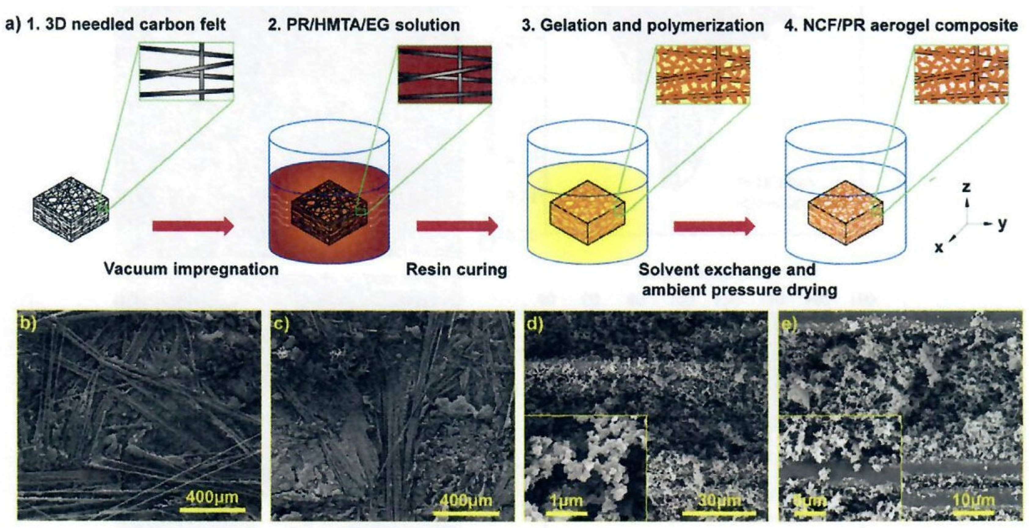
- Cheng, H.; Xue, H.; Hong, C.; Zhang, X. Preparation, mechanical, thermal and ablative properties of lightweight needled carbon fibre felt/phenolic resin aerogel composite with a bird’s nest structure. Compos. Sci. Technol. 2017, 140, 63–72. [Google Scholar] [CrossRef]
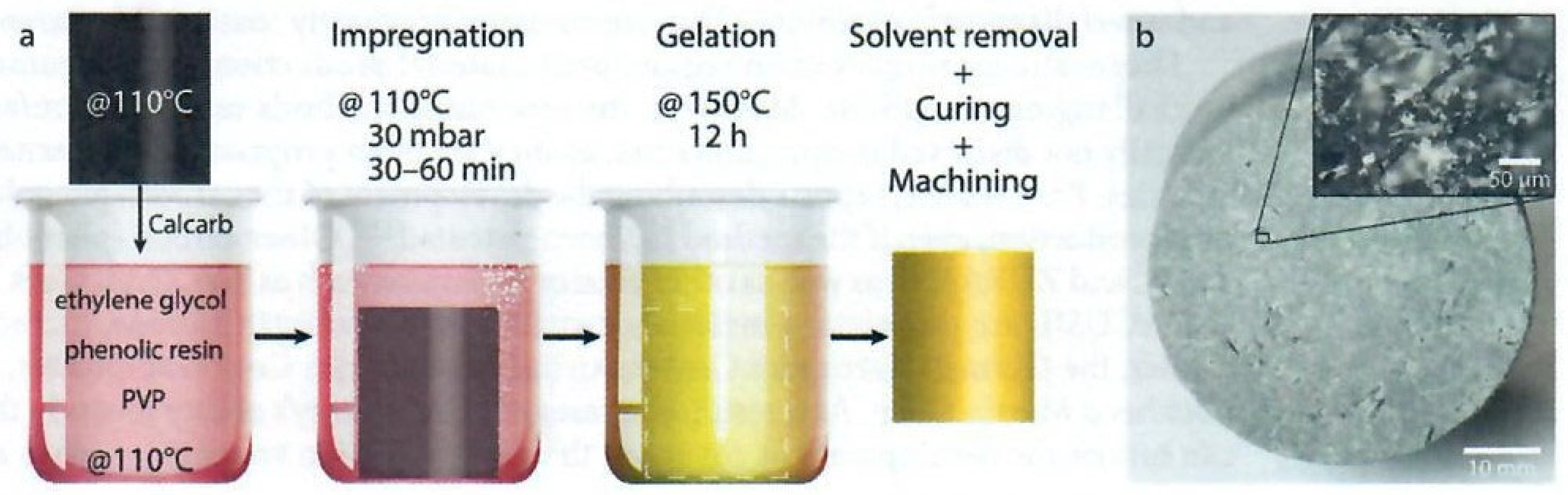
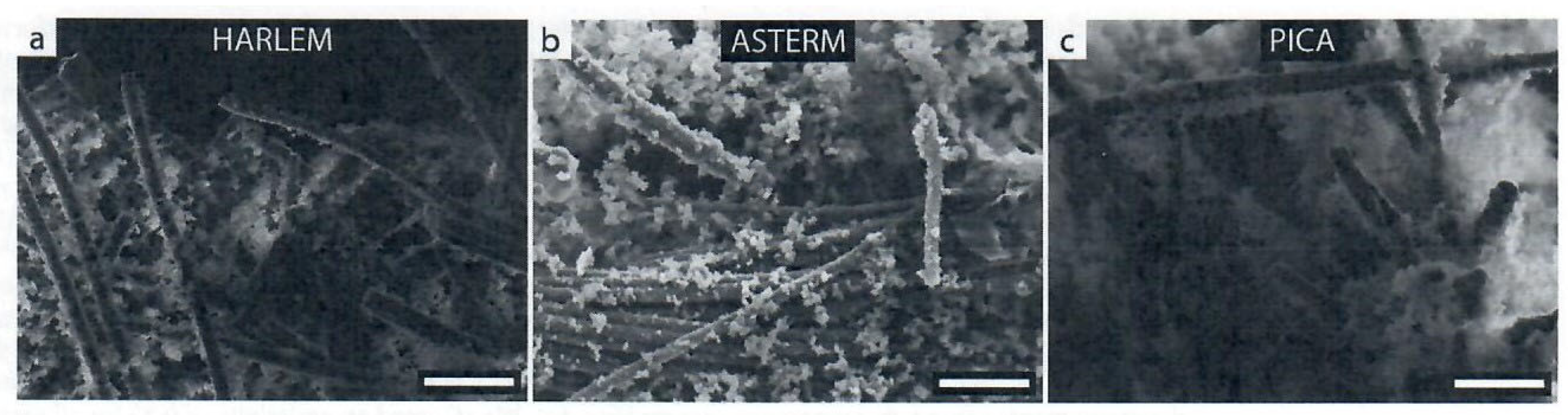
- Poloni, E.; Bouville, F.; Schmid, A.L.; Pelissari, P.I.; Pandolfelli, V.C.; Sousa, M.L.; Tervoort, E.; Christidis, G.; Shklover, V.; Leuthold, J. Carbon ablators with porosity tailored for aerospace thermal protection during atmospheric re-entry. Carbon 2022, 195, 80–91. [Google Scholar]
- Poloni, E.; Grigat, F.; Eberhart, M.; Leiser, D.; Sautière, Q.; Ravichandran, R.; Delahaie, S.; Duernhofer, C.; Hoerner, I.; Hufgard, F. An open carbon–phenolic ablator for scientific exploration. Sci. Rep. 2023, 13, 13135. [Google Scholar]
- Cheng, H.; Fan, Z.; Hong, C.; Zhang, X. Lightweight multiscale hybrid carbon-quartz fiber fabric reinforced phenolic-silica aerogel nanocomposite for high temperature thermal protection. Compos. Part A Appl. Sci. Manuf. 2021, 143, 106313. [Google Scholar] [CrossRef]
- Jin, X.; Wu, C.; Wang, H.; Pan, Y.; Huang, H.; Wang, W.; Fan, J.; Yan, X.; Hong, C.; Zhang, X. Synergistic reinforcement and multiscaled design of lightweight heat protection and insulation integrated composite with outstanding high-temperature resistance up to 2500 °C. Compos. Sci. Technol. 2023, 232, 109878. [Google Scholar]
- Jin, X.; Liu, C.; Huang, H.; Pan, R.; Wu, C.; Yan, X.; Wang, H.; Pan, Y.; Hong, C.; Zhang, X. Multiscale, elastic, and low-density carbon fibre/siliconoxycarbide-phenolic interpenetrating aerogel nanocomposite for ablative thermal protection. Compos. Part B Eng. 2022, 245, 110212. [Google Scholar]
- Jin, X.; Xu, J.; Pan, Y.; Wang, H.; Ma, B.; Liu, F.; Yan, X.; Wu, C.; Huang, H.; Cheng, H. Lightweight and multiscale needle quartz fiber felt reinforced siliconoxycarbide modified phenolic aerogel nanocomposite with enhanced mechanical, insulative and flame-resistant properties. Compos. Sci. Technol. 2022, 217, 109100. [Google Scholar]
- Wang, H.; Quan, X.; Yin, L.; Jin, X.; Pan, Y.; Wu, C.; Huang, H.; Hong, C.; Zhang, X. Lightweight quartz fiber fabric reinforced phenolic aerogel with surface densified and graded structure for high temperature thermal protection. Compos. Part A Appl. Sci. Manuf. 2022, 159, 107022. [Google Scholar]
- Wang, H.; Pan, Y.; Jin, X.; Wu, C.; Huang, H.; Yan, X.; Hong, C.; Zhang, X. Gradient fiber-reinforced aerogel composites using surface ceramicizable-resin densification with outstanding ablation resistance for high-temperature thermal protection. Compos. Sci. Technol. 2022, 230, 109798. [Google Scholar]
- Pan, Y.; Jin, X.; Wang, H.; Huang, H.; Wu, C.; Yan, X.; Hong, C.; Zhang, X. Nano-TiO2 coated needle carbon fiber reinforced phenolic aerogel composite with low density, excellent heat-insulating and infrared radiation shielding performance. J. Mater. Sci. Technol. 2023, 152, 181–189. [Google Scholar]
- Wang, W.; Jin, X.; Huang, H.; Hu, S.; Wu, C.; Wang, H.; Pan, Y.; Hong, C.; Zhang, X. Thermal-insulation and ablation-resistance of Ti-Si binary modified carbon/phenolic nanocomposites for high-temperature thermal protection. Compos. Part A Appl. Sci. Manuf. 2023, 169, 107528. [Google Scholar] [CrossRef]
- Xiong, S.; Yang, Y.; Zhang, S.; Xiao, Y.; Ji, H.; Yang, Z.; Ding, F. Nanoporous polybenzoxazine aerogels for thermally insulating and self-extinguishing materials in aerospace applications. ACS Appl. Nano Mater. 2021, 4, 7280–7288. [Google Scholar] [CrossRef]
- Zhang, S.; Ji, H.; Wang, Z.; Xiao, Y.; Yang, Z.; Wang, J.; Lu, K.; Xu, G.; Xiong, S.; Li, Z. Polybenzoxazine/silica hybrid aerogels for thermally insulating ablation. ACS Appl. Polym. Mater. 2022, 4, 6602–6611. [Google Scholar] [CrossRef]
- Wu, C.; Huang, H.; Jin, X.; Yan, X.; Wang, H.; Pan, Y.; Zhang, X.; Hong, C. Water-assisted synthesis of phenolic aerogel with superior compression and thermal insulation performance enabled by thick-united nano-structure. Chem. Eng. J. 2023, 464, 142805. [Google Scholar] [CrossRef]
- Lorjai, P.; Chaisuwan, T.; Wongkasemjit, S. Porous structure of polybenzoxazine-based organic aerogel prepared by sol–gel process and their carbon aerogels. J. Sol-Gel Sci. Technol. 2009, 52, 56–64. [Google Scholar] [CrossRef]
- Seraji, M.M.; Arefazar, A. Thermal ablation-insulation performance, microstructural, and mechanical properties of carbon aerogel based lightweight heat shielding composites. Polym. Eng. Sci. 2021, 61, 1338–1352. [Google Scholar] [CrossRef]
- Li, J.; Guo, P.; Hu, C.; Pang, S.; Ma, J.; Zhao, R.; Tang, S.; Cheng, H.-M. Fabrication of large aerogel-like carbon/carbon composites with excellent load-bearing capacity and thermal-insulating performance at 1800 °C. ACS Nano 2022, 16, 6565–6577. [Google Scholar] [CrossRef] [PubMed]
- Stawarz, S.; Witek, N.; Kucharczyk, W.; Bakar, M.; Stawarz, M. Thermo-protective properties of polymer composites with nano-titanium dioxide. Int. J. Mech. Mater. Des. 2019, 15, 585–599. [Google Scholar] [CrossRef]
- Yu, Z.L.; Yang, N.; Apostolopoulou-Kalkavoura, V.; Qin, B.; Ma, Z.Y.; Xing, W.Y.; Qiao, C.; Bergström, L.; Antonietti, M.; Yu, S.H. Fire-retardant and thermally insulating phenolic-silica aerogels. Angew. Chem. Int. Ed. 2018, 57, 4538–4542. [Google Scholar] [CrossRef]
- Toader, G.; Diacon, A.; Rusen, E.; Rizea, F.; Teodorescu, M.; Stanescu, P.O.; Damian, C.; Rotariu, A.; Trana, E.; Bucur, F. A facile synthesis route of hybrid polyurea-polyurethane-mwcnts nanocomposite coatings for ballistic protection and experimental testing in dynamic regime. Polymers 2021, 13, 1618. [Google Scholar] [CrossRef]


| Treatment Temperature | /μm | ||
|---|---|---|---|
| Carbon Fibers | BP-0 | BP-15 | |
| RT | 7.118 | 7.118 | 7.118 |
| 800 °C | 6.034 | 6.178 | 6.892 |
| 1000 °C | 5.393 | 5.487 | 6.296 |
| 1200 °C | 4.999 | 5.097 | 5.592 |
| 1400 °C | 4.863 | 6.042 | 6.681 |
| Product Number | Inner Diameter (nm) | Outer Diameter (nm) | Length (µm) | |
|---|---|---|---|---|
| Conventional CNTs | CNTs-010-0 | 3–5 | 8–15 | 3–12 |
| Long CNTs | CNTs-010 | 3–5 | 8–15 | 30–50 |
| Short CNTs | CNTs-007-1 | 3–5 | 8–15 | 0.5–2 |
| Large diameter CNTs | CNTs-014 | 5–15 | >50 | 10–15 |
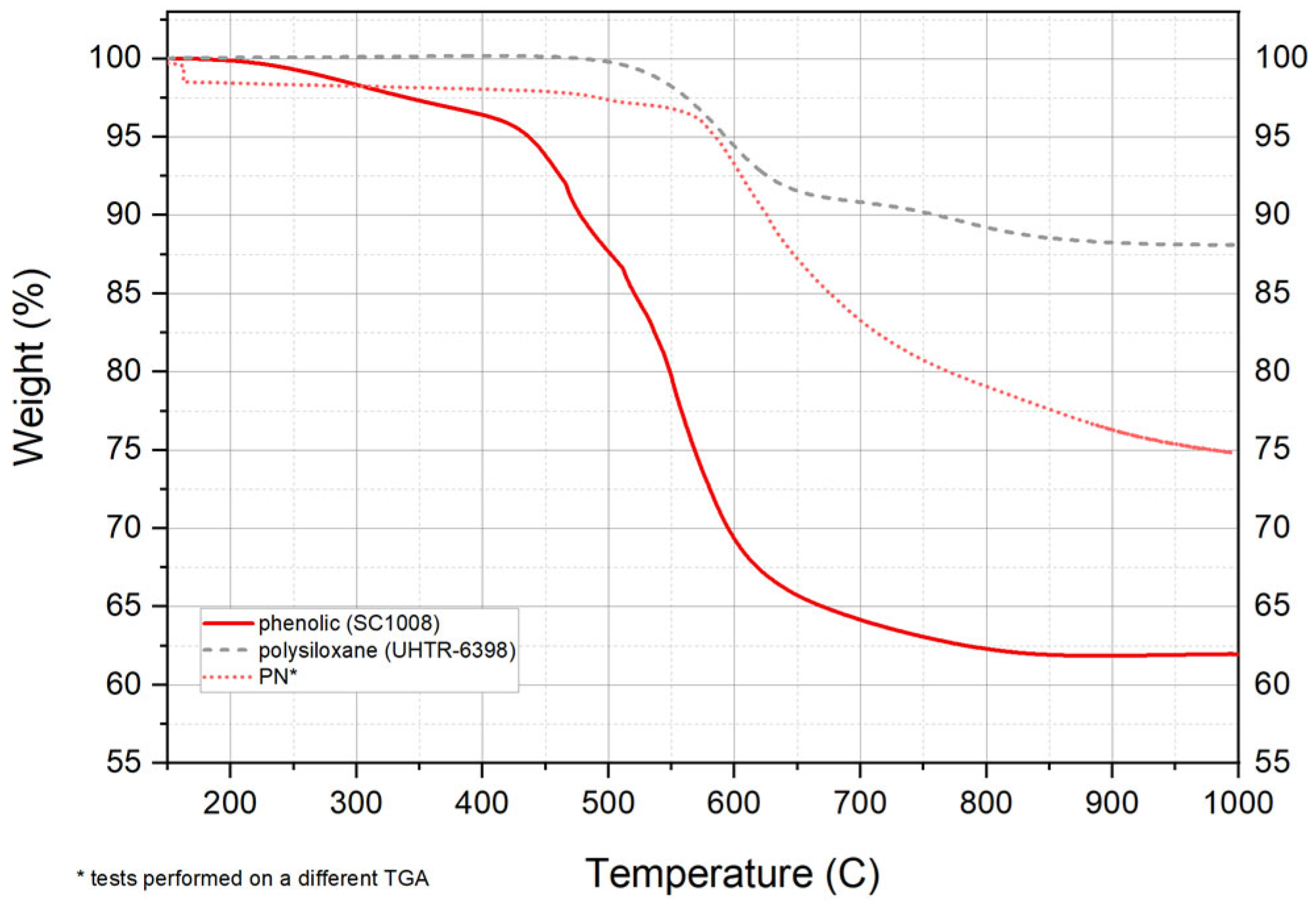
| Material | Td @ 10% (°C) | Char Yield (%) |
|---|---|---|
| UHTR-6398 | 760 | 88.1 |
| PN | 636 | 74.9 |
| SC1008 | 478 | 62.0 |
| Simulated Reentry Conditions | ||
|---|---|---|
| Heat Flux (W/cm2) | Exposure Time (s) | Ablation Parameter (kJ/cm2) |
| 500 | 60 | 30 |
| 1000 | 60 | 60 |
| 1500 | 60 | 90 |
| Sample Type | Cold Wall Heat Flux | Time | Recession | Mass Loss | Peak Surface Temperature | Peak Back Face Heat Soak Temperature | Time to Peak Back Face Heat Soak |
|---|---|---|---|---|---|---|---|
| W/cm2 | s | mm | g | °C | °C | s | |
| AF/U | 1000 | 30 | 2.55 ± 0.87 | 1.05 ± 0.52 | 2181 ± 20 | 149 ± 13 | 200 ± 6 |
| AF/UBC | 1000 | 30 | 2.68 ± 0.78 | 0.57 ± 0.16 | 2162 ± 15 | 166 ± 26 | 199 ± 11 |
| AP/U | 1000 | 30 | 1.98 ± 0.13 | 0.58 ± 0.25 | 2093 ± 28 | 139 ± 18 | 241 ± 3 |
| AP/UBC | 1000 | 30 | 0.98 ± 0.24 | 0.72 ± 0.06 | 2118 ± 7 | 165 ± 6 | 220 ± 15 |
| AP/UBC | 500 | 30 | −0.03 ± 0.11 | 0.40 ± 0.14 | 1779 ± 56 | 146 ± 13 | 213 ± 11 |
| Ablation Characteristics | |||||||
|---|---|---|---|---|---|---|---|
| Component | Aerogel | Density, g/cc | Surface Flame Temperature, °C | Time, s | Linear, mm/s | Mass, g/s | Backside Temperature, °C |
| Q-CF/PSi-75 A | PR C | 0.46–0.515 | 2000 | 300 | 0.017 | 0.011 | ~100 E |
| Q-CF/SPA-2 B | Si/PR D | 0.33 | 2500 G | 30 | 0.058 | 0.014 | 103 F |
| QFPSx | Used Ceramic Resin | |||
|---|---|---|---|---|
| CRx | ZrB2 | SiC | PR | |
| QFPS1 | CR1 | 10 | 0 | 10 |
| QFPS2 | CR2 | 10 | 10 | 20 |
| QFPS3 | CR3 | 10 | 2 | 12 |
| No. | Properties | Before | After |
|---|---|---|---|
| 1 | Bulk density (g cm−3) | 0.60 | 0.58 |
| 2 | Compressive strength (MPa) | 80 ± 3 | 96 ± 5 |
| 3 | Compressive modulus (MPa) | 1557 ± 86 | 1707 ± 92 |
| 4 | Specific strength (MPa g−1 cm−3) | 133 | 155 |
| 5 | Thermal conductivity (W m−1 K−1) | 0.32 | 0.42 |
| 6 | Interlaminar shear strength (MPa) | 15 ± 2 | 17 ± 3 |
| 7 | In-plane shear strength (MPa) | 20 ± 4 | 23 ± 5 |
| Ablative Composites (Resin Is Bolded) | Linear Ablation Rate (LAR) [mm/s] or [%] | Mass Ablation Rate (MAR) [g/s] or [%] | Method of Ablation Test and Conditions | References |
|---|---|---|---|---|
| Boron-modified phenolic resin (PR) with heptaphenyl POSS impregnation of silica fiber (POSSBPR4/silica fiber) | 0.123 (POSSBPR4/silica) and 0.130 (control BPR/silica) mm/s | 0.0602 (POSSBPR4/silica) and 0.0685 (control BPR/silica) g/s | Oxy-acetylene test bed (OTB) at 418.68 W/cm2 for 20 s | Niu et al. [4] |
| A constant amount of MoSi2 to boron phenolic resin and varied B4C into boron-modified phenolic resin impregnation of carbon fiber fabric | 0.013 (20% B4C) and 0.0424 (no B4C) mm/s | 0.0815 (15% B4C) and 0.0840 (20% B4C) g/s | Unknown OTB test conditions | Yang et al. [5] |
| Z pinning effect on interlaminar mechanical and ablation performance of quartz fiber/phenolic composites | No data | No data | Ablation in a flame of 920 °C for 60 s of unknown heat flux | Li et al. [6] |
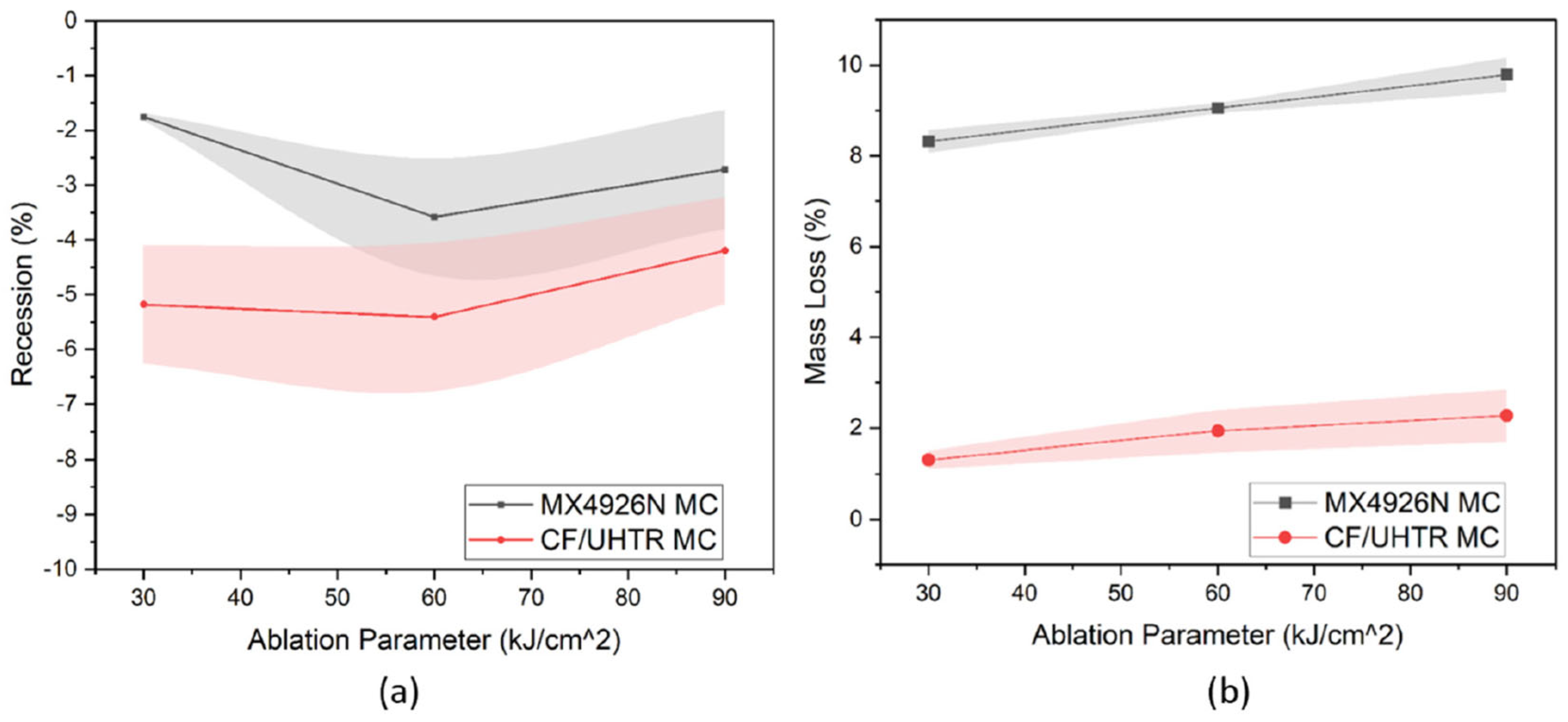
| Polysiloxane resin impregnation of carbon fabric | −5.8, −5.7, and −4.1% for 500, 1000, and 1500 W/cm2, respectively | 1.1, 1.5, and 2% mass loss for 500, 1000, and 1500 W/cm2, respectively | OTB at 500, 1000, and 1500 W/cm2 for 60 s | Hou et al. [14] |
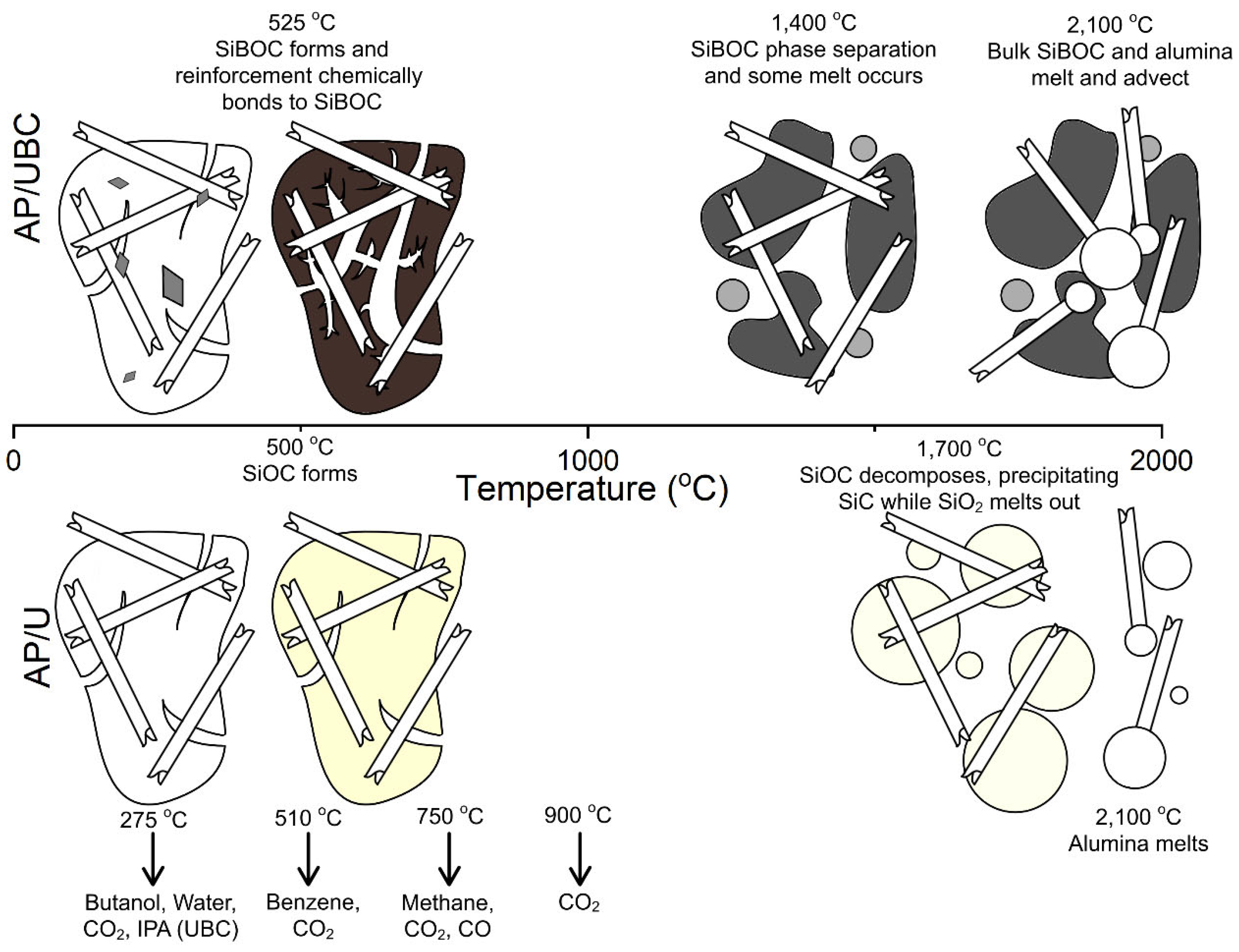
| Polysiloxane resin and boron carbide filler impregnation of alumina fabrics | −0.001 to 0.089 mm/s (Table 5 for more data) | 0.013 to 0.035 g/s (Table 5 for more data) | OTB at 500 and 1000 W/cm2 for 30 s | Yee [16] |
| Phthalonitrile (PN) resin impregnation of carbon fiber (CF/PN) | No data | No data | Butane flame method | Yang et al. [24] |
| Phenolic novolac phthalonitrile (NPN) blends with novolac cyanate ester (NCE) impregnation of carbon fiber | Heat of ablation (8000–12,000 cal/g) | 4.77–5.77% | Radiant heating conditions (~55 W/cm2 for 1200 s) and plasma arc jet (70 and 125 W/cm2 for 50 s) | Sreelal et al. [25] |
| Needle carbon fiber (NCF) felt in phenolic aerogel composite | 0.029 mm/s | No data | OTB at 115 W/cm2 for 33 s | Cheng et al. [28] |
| Low-density (0.27 g/cc) HARLEM using PIPS technology with resole phenolic/ethylene glycol/poly(vinylypyrrolidone) (PR/EG/PVP) impregnation of carbon felt | 48 µm/s | No data | Arc jet testing at 540 W/cm2 for 30 s | Poloni et al. [29,30] |
| Low-density carbon fiber–quartz fiber needled felt (C-QF) reinforced by phenolic–silica aerogel (C-QF/PSi) nanocomposite | 0.017 mm/s | 0.011 g/s | Surface temperature > 2000 °C using oxy-acetylene torch for 300 s; no heat flux measurement | Cheng et al. [31] |
| Low-density carbon fiber–quartz fiber needled felt (C-QF) reinforced by micron silicone aerogel and nano phenolic aerogel | 0.058 mm/s | 0.014 g/s | OTB at 362 W/cm2 for 30 s; surface temperature of 2500 °C | Jin et al. [32] |
| Needled CF felt (NCF) reinforced by SiOC using sol–gel method infiltrate with phenolic aerogel | 0.0282 to 0.0109 mm/s | 0.0186 to 0.0157 g/s | OTB at 150 W/cm2 for 300 s | Jin et al. [33] |
| Needled QF felt (NQF) reinforced by SiOC using sol–gel method on the felt infiltrate with phenolic aerogel (SiQF/PR) | 0.023 mm/s | No data | OTB at 180 W/cm2 for 120 s | Jin et al. [34] |
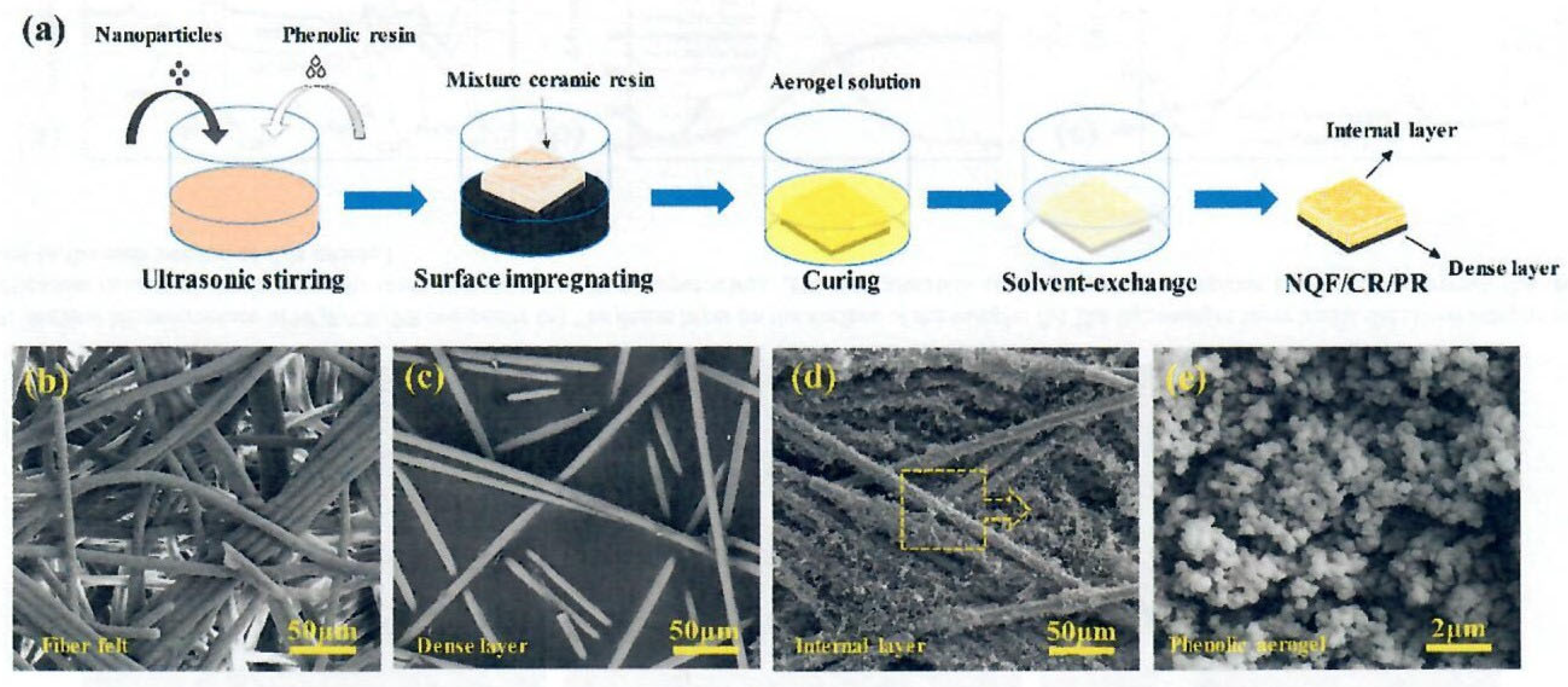
| Low-density (0.20 g/cc) treated needled quartz fiber felt (NQF) with three ceramic particles: ZrB2 (500–800 nm), SiO2 (20–50 nm), and glass in phenolic resin | 0.010 mm/s | 0.020 g/s | OTB at 150 W/cm2 for 90 s at a high temperature > 1700 °C | Wang et al. [35] |
| Low-density (0.14 g/cc) ZrB2 (0.8–1 µm) and SiC (500–800 nm) in phenolic resin in impregnation of QF felt | 0.003 mm/s | 0.016 g/s | OTB testing 150 W/cm2 for 90 s | Wang et al. [36] |
| Low-density nano-TiO2-coated needled carbon fiber reinforced phenolic aerogel composite | 26.2 µm/s | 8.4 mg/s | OTB at 150 W/cm2 for 150 s | Pan et al. [37] |
| Low-density and low-porosity (0.20 g/cc and 85%) TiO2-coated needled carbon fiber felt with phenolic aerogel composites through co-gelation (TiO2-SiO2) | 0.004 and 0.003 mm/s at 100 and 150 W/cm2 for 240 s, respectively | 0.006 and 0.009 g/s for 100 and 150 W/cm2 for 240 s, respectively | OTB at 100 and 150 W/cm2 for 240 s | Wang et al. [38] |
| Medium-density C/C composites (0.6 g/cc) using 3D chopped phenolic fiber felt with phenolic resin | 0.03 µm/s | 0.3% and 6.8% | Oxy-acetylene flame heating tests were conducted at 1800 °C for 900 s, with no heat flux measurement | Li et al. [44] |
| Ablative Composites (Resin Is Bolded) | Thermal Conductivity (k) [W/(m-K)] | Mechanical Properties [MPa] | Char Yield [%] “Different Definition Used by Each Group” | References |
|---|---|---|---|---|
| Boron-modified phenolic resin (PR) with heptaphenyl POSS impregnation of silica fiber (POSSBPR4/silica fiber) | No data | No data | Char yield at 1000 °C increased from 68.1% to 74.2% for POSSBPR containing 20% POSS | Niu et al. [4] |
| Constant amount of MoSi2 to boron phenolic and varied B4C into boron-modified phenolic resin impregnation of carbon fiber fabric | No data | Flexural strengths were determined at elevated temperatures of 800–1400 °C. The best flexural strength is from BP-15 (15% B4C) sample | Highest char yield of 32.9% for the BP-15 sample | Yang et al. [5] |
| Z pinning effect on interlaminar mechanical and ablation performance of quartz fiber/phenolic composites | No data | Interlaminar strength was 3.01 MPa, 84% stronger than that of the control | Char residue of 14.38% at 920 °C in 20/80 O2/N2 for 60 s | Li et al. [6] |
| Polysiloxane resin impregnation of carbon fabric | No data | Tensile/compressive/flexural strengths of CF/UHTR were 49.6/20.5/36.1 ksi | Char yield of CF/UHTR is 93% vs. 83% of CF/phenolic (the highest char yield in this review) | Hou et al. [14] |
| Polysiloxane resin with boron carbide impregnation of alumina fabric | AP/UBC was 0.2–0.5 W/(m-K) | No data | Char residues of boron carbide/UBC were 70–78% in air and 87% in nitrogen; AP/UBC was 66–67.5% in air and 67.7–72% in nitrogen | Yee [15] |
| Phthalonitrile (PN) resin impregnation of carbon fiber (CF/PN) | No data | No data | No data | Yang et al. [24] |
| Phenolic novolac phthalonitrile (NPN) blends with novolac cyanate ester (NCE) impregnation of carbon fiber | Increased k from 0.11 to 0.14 W/(m-K) at 80 °C with increased PN content and reduced back wall temperature (230–260 °C) | Compressive strength increased, with PN content varying from 30 to 55% | High char yields of 75–81% at 900 °C | Sreelal et al. [25] |
| Needle carbon fiber (NCF) felt in phenolic aerogel composite | Low k of 0.131 to 0.230 and 0.093 to 0.183 W/(m-K) in the xy and z directions, respectively | High compressive strength of 1.48 to 11.2 MPa and 0.83 to 4.90 MPa in xy and z directions, respectively | No data | Cheng et al. [28] |
| Low-density (0.27 g/cc) HARLEM using PIPS technology with resole phenolic/ethylene glycol/poly(vinylypyrrolidone) (PR/EG/PVP) impregnation of carbon felt | No data | Compressive strength varied from 0.1 to 0.25 MPa | No data | Poloni et al. [29,30] |
| Low-density carbon fiber–quartz fiber needled felt (C-QF) reinforced by phenolic–silica aerogel nanocomposite (C-QF/PSi) | Low k of 0.112 W/(m-K) | Compressive strength varied from 12.7 to 17.01 MPa and 5.96 to 7.51 MPa in the xy and z directions, respectively | Char yield of 55.45% for control PR vs. 60.79% for PSi100 | Cheng et al. [31] |
| Low-density carbon fiber–quartz fiber needled felt (C-QF) reinforced by micron silicone aerogel and nano phenolic aerogel | Low k of 0.178–0.589 and 0.44–0.060 W/(m-K) in xy and z directions, respectively. The increase in the xy direction is attributable to increased CF content. | Tensile/flexural strengths of Q-CF/SPA were 16.9/11.2 MPa vs. QF/SPA of 9.74/8.18 MPa and values of 10.11/8.81 MPa for CF/SPA. Exhibited higher strengths for the aerogel hybrid composite than either of the pure carbon or quartz fibers | No data | Jin et al. [32] |
| Needled CF felt (NCF) reinforced by SiOC using sol-gel method infiltrate with phenolic aerogel | Low k of 0.068 W/(m-K) | Excellent compressive strength of 5.83 and 4.57 MPa in xy and z directions, respectively | Char yield residues for PR NCF to SiOC-PR increased from 75.96% to 80.59% | Jin et al. [33] |
| Needled QF felt (NQF) reinforced by SiOC using sol–gel method on the felt infiltrate with phenolic aerogel (SiQF/PR) | No data | Excellent compressive strength of 4.20 MPa and 3.34 MPa in the xy and z directions, respectively | Exhibited char residues at 1200 °C of 82.7% in argon and 66.3% in air | Jin et al. [34] |
| Low-density (0.20 g/cc) treated needled quartz fiber felt (NQF) with three ceramic particles: ZrB2 (500–800 nm), SiO2 (20–50 nm), and glass in phenolic resin | No data | Tensile/bending strength for the dense layer was 39.2/57.2 MPa, attributable to the dense layer in the xy direction | Char residues in argon were 71.35% for the dense layer and 80.69% for the internal lightweight char layer | Wang et al. [35,36] |
| Low-density (0.14 g/cc) ZrB2 (0.8–1 µm) and SiC (500–800 nm) in phenolic resin in impregnation of QF felt | Low k of 0.0756 W/(m-K) | Tensile/bending strengths were 11.2/16.2 MPa. Compressive strength was 0.48 MPa. | Char residue of 82.1% | Wang et al. [37] |
| Low-density (0.30–0.32 g/cc) nano-TiO2-coated needled carbon fiber-reinforced phenolic aerogel composite | Low k of 0.312 and 0.034 W/(m-K) in xy and z directions, respectively (lowest k in this review) | No data | Char residue of 13.9% at 1300 °C in air | Pan et al. [38] |
| Low-density and low-porosity (0.20 g/cc and 85%) TiO2-coated needled carbon fiber felt with phenolic aerogel composites through co-gelation (TiO2-SiO2) | Low k of 0.0756 W/(m-K) | No data | No data | Wang et al. [37] |
| Medium-density C/C composites (0.6 g/cc) using 3D chopped phenolic fiber felt with phenolic resin | Low k of 0.32 W/(m-K) | High compressive strength of 80 MPa, interlaminar strength of 15 MPa, and in-plane shear strength of 20 MPa (more data in Table 8) | No data | Li et al. [44] |
Disclaimer/Publisher’s Note: The statements, opinions and data contained in all publications are solely those of the individual author(s) and contributor(s) and not of MDPI and/or the editor(s). MDPI and/or the editor(s) disclaim responsibility for any injury to people or property resulting from any ideas, methods, instructions or products referred to in the content. |
© 2025 by the authors. Licensee MDPI, Basel, Switzerland. This article is an open access article distributed under the terms and conditions of the Creative Commons Attribution (CC BY) license (https://creativecommons.org/licenses/by/4.0/).
Share and Cite
Koo, J.H.; Wagner, K.; Pilato, L.A.; Wu, H. Polymer Nanocomposite Ablatives—Part III. J. Compos. Sci. 2025, 9, 127. https://doi.org/10.3390/jcs9030127
Koo JH, Wagner K, Pilato LA, Wu H. Polymer Nanocomposite Ablatives—Part III. Journal of Composites Science. 2025; 9(3):127. https://doi.org/10.3390/jcs9030127
Chicago/Turabian StyleKoo, Joseph H., Kaelyn Wagner, Louis A. Pilato, and Hao Wu. 2025. "Polymer Nanocomposite Ablatives—Part III" Journal of Composites Science 9, no. 3: 127. https://doi.org/10.3390/jcs9030127
APA StyleKoo, J. H., Wagner, K., Pilato, L. A., & Wu, H. (2025). Polymer Nanocomposite Ablatives—Part III. Journal of Composites Science, 9(3), 127. https://doi.org/10.3390/jcs9030127