Article

Thermodynamic Analysis on Complex Oxides Formed by Aerodynamic Heating for Ultrahigh-Temperature Ceramic Matrix Composites

1
Department of Mechanical Engineering, Tokyo University of Science, Tokyo 125-8585, Japan
2
Department of Materials Science and Technology, Tokyo University of Science, Tokyo 125-8585, Japan
*
Author to whom correspondence should be addressed.
J. Compos. Sci. 2025, 9(2), 87; https://doi.org/10.3390/jcs9020087
Submission received: 26 December 2024 / Revised: 29 January 2025 / Accepted: 10 February 2025 / Published: 13 February 2025

Abstract

:
The oxidation and recession of carbon-fiber-reinforced ultrahigh-temperature ceramic matrix composites (C/UHTCMCs) fabricated via reactive melt infiltration (RMI) using Zr-Ti alloys with three different compositions are evaluated via an arc-jet tunnel test at temperatures above 2000 °C for 60 s. Thermodynamic evaluations show that the recession of the UHTCMCs is prevented by the formation of a solid solution of ZrTiO4 on their exposed surface. Because an increase in the Zr content increases the melting temperature of ZrTiO4, the recession of the composites increases as the Zr content in the infiltrated alloys decreases. UHTCMCs fabricated with Zr-20at%Ti showed the least recession (<5%).

1. Introduction

Ultrahigh-temperature ceramics (UHTCs), which are transition metal diborides, carbides, and nitrides with a melting point of >3000 °C, are expected to be used as hot structural components in re-entry and hypersonic vehicles [1,2,3,4,5,6,7,8,9,10,11,12]. SiC-particle-dispersed ZrB2 ceramics have been extensively investigated over the recent decades. Several studies regarding ZrB2-SiC demonstrated the effectiveness of SiC reinforcement in reducing surface oxidation through the evaporation of B2O3 [13,14,15,16,17,18,19,20]. However, a porous subsurface layer was formed by the selective oxidation of SiC, and gaseous SiO was generated because of SiC oxidation occurring above 1700 °C under low oxygen partial pressures [21,22,23,24,25,26].
Recently, carbon-fiber-reinforced ZrB2-SiC matrix composites (carbon-fiber-reinforced UHTC matrix composites (C/UHTCMCs)) have been developed, and their manufacturing processes and performance have been characterized [27,28,29,30,31,32,33]. However, the degradation mechanisms of the composites are similar to those of ZrB2-SiC ceramics, and improvements in their heat and oxidation resistance above 1700 °C remain unresolved.
Hence, the authors developed a C/UHTCMC without SiC (and Si) via a Zr-Ti alloy reactive melt infiltration (RMI) process. In conventional MI processes using Si as the infiltration medium [34,35,36], the melting point of residual Si and the lower melting point due to the formation of the ZrSi2-Si eutectic phase must be addressed [27,37,38]. Hence, researchers have focused on Si-free materials composed of five or more UHTC compounds, which are referred to as refractory high-entropy ceramics (i.e., compositionally complex ceramics or high-entropy sublattice ceramics [39]). Although they demonstrate high hardness (HV = 66 G Pa), low thermal conductivity (~5.4 W/mK), and better recession behavior in oxidizing atmospheres compared with SiC containing UHTCs [40,41,42,43,44,45,46], their complex crystal structure and unexpected interaction of constituent materials render the development of engineering design for components difficult. As a simple solution, Zhou et al. formed a ZrC matrix in situ carbon-fiber-based preform via Zr MI [47,48]. Compared with Si, Zr has a higher melting temperature (1855 °C), thus rendering it suitable for Zr MI, which requires a high temperature (>1900 °C). The process temperature for infiltration is a critical factor for the in situ formation of a Zr-based carbide matrix in the preform. The application of Zr-Ti alloy has been proposed as the Zr-Ti alloy is an all-proportional solid solution, and the minimum liquidus temperature of the Zr-Ti system is ~1560 °C, which is higher than the melting point of the Si and ZrSi2-Si eutectic [49]. The melting point of unreacted residual components is considerably higher than that of Si. Additionally, the residual alloys are expected to decrease because the Gibbs free energy of the reaction between Zr-C and Ti-C is higher than that of Si-C in the temperature range of 1500–1800 °C. In previous studies, the heat resistance of C/UHTCMCs was investigated via arc-wind tunnel testing, and the effectiveness of Zr-rich alloys (and the formation of a ZrO2-rich surface scale) in terms of recession resistance was explained. However, temperature during exposure for these studies was not steady owing to the short exposure time, and the result obtained by steady state exposure will help in the development of design for materials used in extreme environments. Hence, this study is performed to elucidate the thermodynamic relationship between surface oxides and Zr content.

2. Experimental Procedure

2.1. Material

The composite used in this study was fabricated via the Zr-Ti alloy MI. Polyacrylonitrile (PAN)-based carbon-fiber-reinforced carbon matrix (C/C, FS-320, CFC Design, Sabae, Fukui, Japan) cross-ply (0°/90°) laminates with a fiber volume fraction of approximately 20% were used as a preform. In addition, porosity of C/C preform is ~20%. Typical microstructure was shown in Figure 1a,b. The preforms used in the present study are the same as the ones used in a previous study [50].
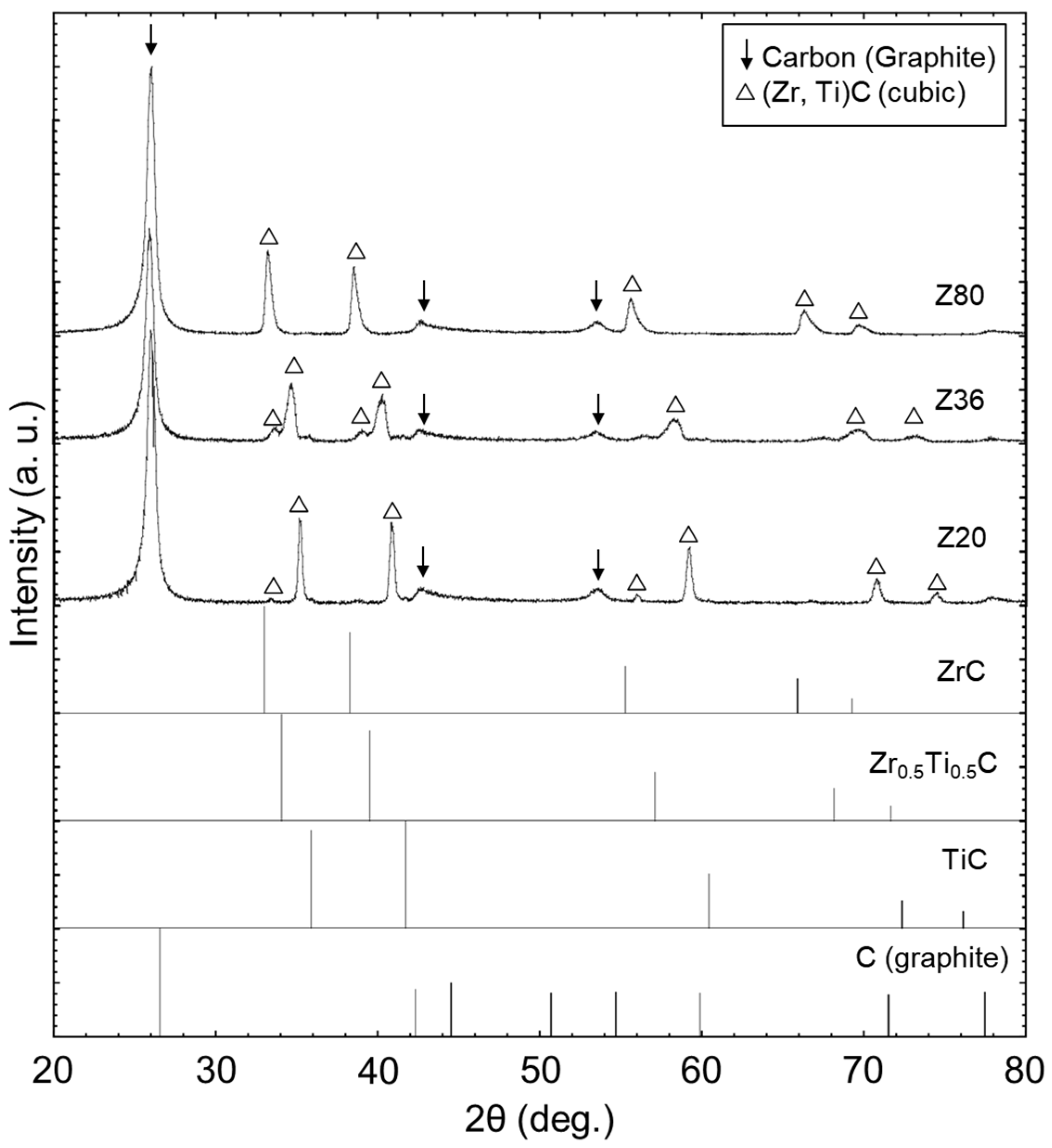
Three types of Zr-Ti alloys with different atomic compositions (Zr:Ti = 20:80, 36:64, and 80:20) were fabricated from Ti and Zr chunks (purity: 97–99%, Kojundo Chemical Laboratory, Co., Ltd., Sakado, Saitama, Japan) using an arc-melting furnace (NEV-ADR03, Nissin Giken Corporation, Iruma, Saitama, Japan). Prior to melting, the evaporation and introduction of Ar (purity: 99.999%) were repeated thrice, and the vacuum level in the chamber was set to −0.06 atm. To achieve uniform microstructures, the melting and solidification of the alloys were repeated four or five times. The Zr-Ti alloys were infiltrated into the C/C using a carbon heater furnace (Iida Kogyo, Model: Heat-treatment furnace for the regeneration and recovery of creep/fatigue-deteriorated damaged parts, Kawaguchi, Saitama, Japan). A preform measuring 50 mm × 50 × 10 t (mm) was used. Before the Zr-Ti alloy MI, the evaporation and introduction of Ar (purity: 99.999%) were repeated thrice to reduce residual oxygen in the furnace. The Zr-Ti alloys were infiltrated at 1750 °C for 15 min in Ar [51]. The temperature in the furnace was measured using a C-type thermocouple and controlled using a proportional (integral) program. Hereinafter, the as-fabricated composites using alloys with Zr–Ti ratios of 20:80, 36:64, and 80:20 are denoted as Z20, Z36, and Z80, respectively. Detailed preparation method has been reported elsewhere [50,51,52]. As a result, alloys were successfully infiltrated in C/C preforms shown in Figure 2a–c. The matrix of Z20, Z36, and Z80 is composed of the solid solution of TiC and ZrC (shown in Figure 3). Notably, no residual Zr-Ti alloys are recognized [50,51,52]. For thermal degradation by RMI, the bending strength of samples at room temperature (~25 °C) and 1500 °C in Ar atmosphere was ~120–220 MPa, which is similar to the bending strength of C/C preforms (130–180 MPa). Therefore, thermal damages during process were ignored in the present study.

2.2. Arc-Wind Tunnel Testing

Aerodynamic heating was conducted at an arc-wind tunnel facility at ISAS/JAXA, Japan. A disk-shaped specimen with a diameter and a thickness of 20 mm and ~10 mm, respectively, was used for characterization. The tests were performed at L = 100 mm, where L is the distance between the nozzle tip and specimen surface. In previous studies [50,52], the maximum temperature recorded on the surface exceeded 2000 °C. During the tests, the surface temperature was measured using a radiation thermometer. The emissivity of the thermometer was set to 0.90, which is typical for carbon materials [53]. The dynamic pressure was measured using a Gardon gauge.
After the test was completed, the morphologies and elemental distributions of the surfaces and cross-sections of the specimens were observed using optical microscopy and scanning electron microscopy (SEM, TM-3000, Hitachi High Technologies Co. Ltd., Tokyo, Japan) equipped with energy-dispersive spectrometry (EDS, Oxford Instruments, Oxford, UK). For cross-sectional observation, the samples were embedded in epoxy resin, and the cross-section was exposed by cutting the center of the embedded samples. Subsequently, the cross-section was polished using 1 μm diamond slurry.
The relationship among the formation mechanisms of compounds on the surface, temperature, and oxygen partial pressure during the arc-wind tunnel tests was investigated from a thermodynamic viewpoint. In this study, a volatility diagram of the TiC-ZrC system was designed using the thermodynamic calculation software (FactSage 8.1, GTT-technologies, Herzogenrath, Germany). The Fact PS, SpMCBN, and FT-oxide databases were selected as the solution and compound databases.

3. Results

The surface-temperature profiles of the composites are shown in Figure 4. The maximum temperature reached was ~2200 °C or higher. Because the emissivity of the samples decreased due to the formation of surface oxide scales, the surface temperature was higher than the measured value. The surface temperature of the C/C used as a preform was considerably lower than those of others because oxide scales with lower thermal conductivity (ZrO2: ~2 W/m·K; TiO2: ~7–10 W/m·K [54]) were not formed on the surface. The heat flux under these test conditions was ~4.6 MW/m2, and the dynamic pressure was approximately 13 kPa, which is similar to the value reported in the literature [50]. This indicates that steady-state exposure above 2200 °C was successfully conducted in the arc-wind tunnel test for 60 s.
The surface morphologies obtained by optical microscopy after testing are shown in Figure 5a–d. After the tests were completed, the exposed surfaces appeared white. In particular, a reticulated scale formed on the surface of Z80, although not entirely. Similar to all the other specimens, several grooves appeared along the left–right direction on the surfaces of the C/C composites. The SEM observations of the surfaces (Figure 6a–c) confirmed that the grooves were filled with surface scales in Z20, Z36, and Z80. It appears that oxides were formed on the surface in common with all composites despite their difference in composition. This result is reasonable because the Gibbs free energies for the oxidation of TiC and ZrC are similar. Then, it is considered that solid solutions of ZrO2, TiO2, and ZrTiO4 (hereinafter referred to as ZrO2 s.s., TiO2 s.s., and ZrTiO4 s.s., respectively) were formed in the ZrO2-TiO2 system because of the result from similar tests exposed at 30 s.
The morphologies and distributions of O, C, Zr, and Ti in the cross-section are shown in Figure 7a–c. Here, smooth surfaces with thin scales (a thickness of less than 10 μm) were observed in Z20 and Z36, whereas oxide-scale protrusion was observed in Z80. Koide et al. discussed the differences in morphologies based on the amount of ZrO2 that formed solid and porous structures on the surface at 4.6 MW/m2 [50]. The result corresponded to the XRD patterns, as the XRD peak for carbon ((002)) was more prominent for Z20 and Z36 than for Z80.
The normalized thickness of the specimen hN is defined as hN = ha/hb, where hb and ha are the thicknesses of the specimens before and after the test, respectively. The relationship between the Zr content and hN is shown in Figure 8. For comparison, the test result after 30 s [50] is presented as well. The hN was considerably lower than 1 in all the tests, thereby revealing that the recession of the surface continued during the arc-wind tunnel tests. Under similar test conditions, the hN values of the C/C, Z20, and Z36 decreased. However, that of Z80 was maintained even after long exposure, and the contribution of the Zr-rich carbide matrix to recession resistance was evident. Focusing on the surface after exposure (Figure 6), cracks extending in the x direction are filled with oxides for Z20, whereas these cracks not filled with oxides are recognized for Z36. Then, it is considered that cracks not filled with oxides act as oxygen paths toward the unoxidized region and they accelerate oxidation and recession. Thus, the normalized thickness of Z36 becomes thinner than that for Z20. Notably, Z80 shows the least recessions (<5%). Then, recession rate is defined as recession length (hb − ha) as a function of exposure time. Since hb is ~10 mm, hb − ha is in the range of ~1–2 mm and the recession rate is 0.83(Z80) − 3.3(Z36) × 10−2 mm/s. For similar test for similar conditions, the recession rate for C/SiC and C/SiC-HfC composites exposed by oxyacetylene torch (~4.2 MW/m2) at the temperature distribution of ~2500–3200 °C for 20 s is ~2.2–8.3 mm/s [55]. The result indicates that the recession rate of Z80 is lower than other similar UHTCMCs.
Assuming that the surface scale comprises solid solutions of ZrO2, TiO2, and ZrTiO4 with a similar ratio as the infiltrated alloy, TiO2-rich oxides transform from solid scales to liquids above 2000 °C because the melting point of TiO2 is ~1840 °C. Furthermore, the dynamic pressure promotes the flow of liquid oxides from the surface. On the contrary, the melting point of ZrO2 is ~2700 °C and ZrO2-rich oxides maintain solid state even at ~2400 °C. These are the primary reasons contributing to the differences in surface morphologies. As an important result obtained by steady state exposure at above 2000 °C for 60 s, the normalized thickness of Z80 exposed for 30 s and 60 s is almost the same and it indicates that the increase in melting point of formed oxides will improve recession behavior of these composites. However, the formation mechanism of the solid solutions of the oxides (TiO2 s.s., ZrO2 s. s., and ZrTiO4 s.s.) must be discussed further.

4. Discussion

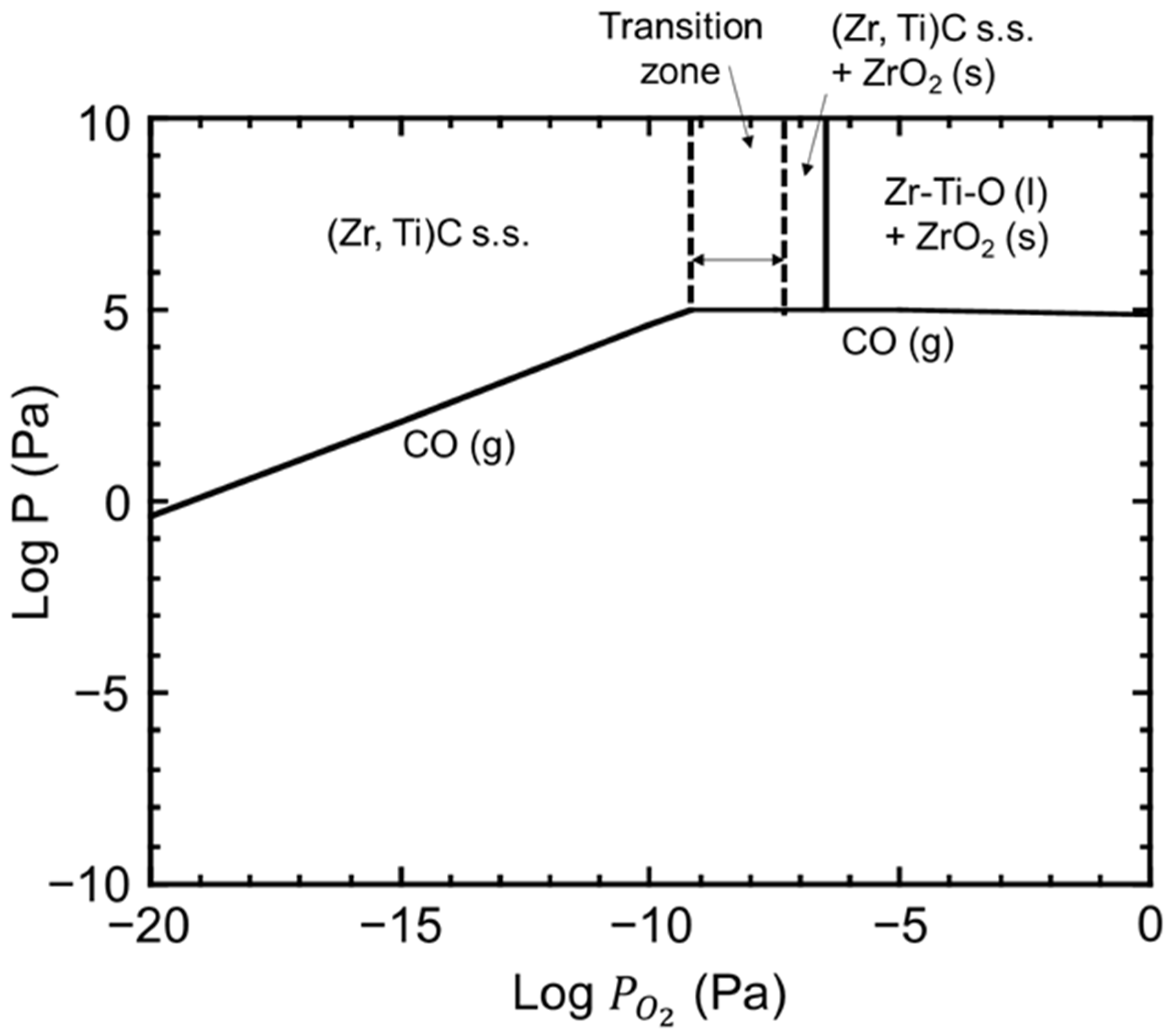
The volatility diagram for the TiC-ZrC system at 2000 °C is shown in Figure 9. Assuming that formed oxides are as shown, (Zr, Ti)C began to oxidize when the oxygen partial pressure ( P O 2 ) reached ~10−9 and ~10−8 Pa. Because the difference between P O 2 required for the oxidation of TiC and ZrC was considerably small, the selective oxidation of TiC or ZrC was unlikely to occur. However, accurate predictions based on the database could not be achieved. However, (Zr, Ti)C oxidized partially when P O 2 reached 10−9–10−6. Furthermore, ZrO2 formed selectively in P O 2 ranging from 10−7 to 10−6. In the P O 2 of 10−9–10−7, (Zr, Ti)C s.s. might have oxidized partially. However, the exact compounds formed within this P O 2 range remain unknown. The formation of oxycarbides has been reported to be the partial oxidation of carbides [56,57,58,59,60]. This is expected to occur via the following reaction:
(Zr, Ti)C + 1/2(1 − x)O2 → (Zr, Ti)CxO1−x + (1 − x)C
where x: constant.
Although the formation of C is natural under low oxygen partial pressures, further thermodynamic analyses are required to clarify the reaction in the P O 2 ranges. For P O 2 > 10−6, ZrO2 and a liquid phase composed of Zr-Ti-O were formed in accordance with the volatility diagram. In particular, ZrTiO4 s.s. was formed from liquid Zr-Ti-O during cooling in the arc-wind tunnel tests. Because the Gibbs free energy of oxidation for ZrC (−550 kJ/mol) and TiC (−480 kJ/mol) is similar at 2000 °C [52], the ratios of Zr and Ti in oxides are similar to that in the matrix [50]. Within the Zr (or Ti) content range of the fabricated composites, the ZrO2 s.s. and liquid phases were stable. This result is consistent with the evaluation based on the volatility diagram at 2000 °C. The pseudo-phase diagram of TiO2-ZrO2 [23,32] also clearly shows that the surfaces of Z20 and Z36 were coated with liquid, whereas the surface of Z80 was coated with ZrO2 s.s. and liquid. In the arc-wind tunnel test, the liquid phase disappeared from the surface owing to the dynamic pressure, and the exposed surface recessed significantly. By contrast, the liquid phases of Z80 remained unchanged because the ZrO2 s.s. supported the liquid phase in the test, whereas recession was suppressed compared with the cases of Z20 and Z36. These results suggest that the increase in the melting point of the oxides on the surface contributed to the decrease in the recession during exposure at temperatures above 2000 °C. Thus, a design for increasing the liquidus temperature in the ZrO2-TiO2 system is required to further improve the recession behavior of (Zr, Ti) C-based composites.

5. Conclusions

In this study, microstructural analysis and thermodynamic assessment were conducted for C/UHTCMCs fabricated via the Zr–Ti alloy MI. The surface recession after dynamic heating at temperatures above 2000 °C, as generated in the arc-wind tunnel testing facility, reduced in the composite with Zr-rich carbide matrices because its surface was coated with the ZrO2 s.s. Moreover, the liquid phase was composed of Zr-Ti-O, which partially maintained the solid phase above 2000 °C compared with the case of the Ti-rich composite. Although the addition of Ti decreased the MI temperature and residual alloys were not observed for the Zr-Ti alloy, the recession of the composites during the test decreased as the Zr content increased because the formation of a liquid phase was prevented. An optimal design for forming a solid oxide solution with a high melting point can decrease the recession of the composites.

Author Contributions

Conceptualization, R.I. and Y.A.; methodology, R.I. and Y.A.; software, Y.A.; validation, R.I., M.T. and Y.A.; formal analysis, R.I. and Y.A.; investigation, M.T.; resources, R.I.; data curation, R.I. and Y.A.; writing—original draft preparation, R.I., M.T. and Y.A.; writing—review and editing, R.I. and Y.A.; visualization, M.T.; supervision, R.I.; project administration, R.I.; funding acquisition, R.I. All authors have read and agreed to the published version of the manuscript.

Funding

This study was partially supported by the Japan Society for the Promotion of Science (JSPS) KAKENHI (Grant-in-Aid for Challenging Exploratory Research), Grant No. 21K18782, and JSPS KAKENHI (Grant-in-Aid for Early-Career Scientists), Grant No. 22K14152.

Data Availability Statement

Dataset is available on request from the authors.

Acknowledgments

The results of this study were obtained using the Arc Heating Facility of the Institute of Space and Astronautical Science, Japan Aerospace Exploration Agency. We are very grateful to Noriatsu Koide, Takayuki Shimoda, and Tetsuo Yoshida for their assistance with the arc-wind tunnel tests.

Conflicts of Interest

The authors declare no conflicts of interest.

Abbreviations

The following abbreviations are used in this manuscript:
UHTCsUltrahigh-temperature ceramics
UHTCMCsUltrahigh-temperature ceramic matrix composites
C/UHTCMCsCarbon-fiber-reinforced UHTCMCs
RMIReactive melt infiltration
C/CCarbon-fiber-reinforced carbon composites
ISASInstitute of Space and Astronautical Science
JAXAJapan Aerospace Exploration Agency
SEMScanning electron microscope
EDSEnergy-dispersive spectroscopy
XRDX-ray diffraction
s.s.Solid solution

References

  1. Levine, S.R.; Opila, E.J.; Halbig, M.C.; Kiser, J.D.; Singh, M.; Salem, J.A. Evaluation of Ultra-High Temperature Ceramics for Aeropropulsion Use. J. Eur. Ceram. Soc. 2002, 22, 2757–2767. [Google Scholar] [CrossRef]
  2. Fahrenholtz, W.G.; Hilmas, G.E.; Talmy, I.G.; Zaykoski, J.A. Refractory Diborides of Zirconium and Hafnium. J. Am. Ceram. Soc. 2007, 90, 1347–1364. [Google Scholar] [CrossRef]
  3. Ni, D.; Cheng, Y.; Zhang, J.; Liu, J.X.; Zou, J.; Chen, B.; Wu, H.; Li, H.; Dong, S.; Han, J.; et al. Advances in Ultra-High Temperature Ceramics, Composites, and Coatings. J. Adv. Ceram. 2022, 11, 1–56. [Google Scholar] [CrossRef]
  4. Sziroczak, D.; Smith, H. A Review of Design Issues Specific to Hypersonic Flight Vehicles. Prog. Aerosp. Sci. 2016, 84, 1–28. [Google Scholar] [CrossRef]
  5. Wuest, W. Review of German Work on Controlled Re-Entry Technology. Prog. Aerosp. Sci. 1983, 20, 217–318. [Google Scholar] [CrossRef]
  6. Talmy, I.G.; Zaykoski, J.A.; Opeka, M.M. High-Temperature Chemistry and Oxidation of ZrB2 Ceramics Containing SiC, Si3N4, Ta5Si3, and TaSi2. J. Am. Ceram. Soc. 2008, 91, 2250–2257. [Google Scholar] [CrossRef]
  7. Savino, R.; De Stefano Fumo, M.; Paterna, D.; Serpico, M. Aerothermodynamic Study of UHTC-Based Thermal Protection Systems. Aerosp. Sci. Technol. 2005, 9, 151–160. [Google Scholar] [CrossRef]
  8. Wuchina, E.; Opila, E.; Opeka, M.; Fahrenholtz, W.; Talmy, I. UHTCs: Ultra-High Temperature Ceramic Materials for Extreme Environment Applications. Electrochem. Soc. Interface 2007, 16, 30–36. [Google Scholar]
  9. Zoli, L.; Vinci, A.; Galizia, P.; Gutièrrez-Gonzalez, C.F.; Rivera, S.; Sciti, D. Is Spark Plasma Sintering Suitable for the Densification of Continuous Carbon Fibre—UHTCMCs? J. Eur. Ceram. Soc. 2020, 40, 2597–2603. [Google Scholar] [CrossRef]
  10. Parthasarathy, T.A.; Cinibulk, M.K.; Opeka, M. Modeling and Evaluating the Environmental Degradation of UHTCs under Hypersonic Flow. In Ultra-High Temperature Ceramics: Materials for Extreme Environment Applications; Wiley: Hoboken, NJ, USA, 2014; pp. 267–290. ISBN 9781118700. [Google Scholar] [CrossRef]
  11. Borrelli, R.; Riccio, A.; Tescione, D.; Gardi, R.; Marino, G. Thermo-Structural Behaviour of an UHTC Made Nose Cap of a Reentry Vehicle. Acta Astronaut. 2009, 65, 442–456. [Google Scholar] [CrossRef]
  12. Pulci, G.; Tului, M.; Tirillò, J.; Marra, F.; Lionetti, S.; Valente, T. High Temperature Mechanical Behavior of UHTC Coatings for Thermal Protection of Re-Entry Vehicles. J. Therm. Spray Technol. 2011, 20, 139–144. [Google Scholar] [CrossRef]
  13. Inoue, R.; Arai, Y.; Kubota, Y.; Kogo, Y.; Goto, K. Oxidation of ZrB₂ and Its Composites: A Review. J. Mater. Sci. 2018, 53, 14885–14906. [Google Scholar] [CrossRef]
  14. Opila, E.; Levine, S.; Lorincz, J. Oxidation of ZrB2- and HfB2-Based Ultra-High Temperature Ceramics: Effect of Ta Additions. J. Mater. Sci. 2004, 39, 5969–5977. [Google Scholar] [CrossRef]
  15. Fahrenholtz, W.G. The ZrB2 Volatility Diagram. J. Am. Ceram. Soc. 2005, 88, 3509–3512. [Google Scholar] [CrossRef]
  16. Peng, F.; Speyer, R.F. Oxidation Resistance of Fully Dense ZrB2 with SiC, TaB2, and TaSi2 Additives. J. Am. Ceram. Soc. 2008, 91, 1489–1494. [Google Scholar] [CrossRef]
  17. Silvestroni, L.; Meriggi, G.; Sciti, D. Oxidation Behavior of ZrB2 Composites Doped with Various Transition Metal Silicides. Corros. Sci. 2014, 83, 281–291. [Google Scholar] [CrossRef]
  18. Karlsdottir, S.N.; Halloran, J.W.; Henderson, C.E. Convection Patterns in Liquid Oxide Films on ZrB2-SiC Composites Oxidized at a High Temperature. J. Am. Ceram. Soc. 2007, 90, 2863–2867. [Google Scholar] [CrossRef]
  19. Shugart, K.; Liu, S.; Craven, F.; Opila, E. Determination of Retained B2O3 Content in ZrB2-30 Vol% SiC Oxide Scales. J. Am. Ceram. Soc. 2015, 98, 287–295. [Google Scholar] [CrossRef]
  20. Zhang, S.C.; Fahrenholtz, W.G.; Hilmas, G.E. Oxidation of ZrB2 and ZrB2-SiC Ceramics with Tungsten Additions. ECS Trans. 2009, 16, 137–145. [Google Scholar] [CrossRef]
  21. Jacobson, N.S.; Myers, D.L. Active Oxidation of SiC. Oxid. Met. 2011, 75, 1–25. [Google Scholar] [CrossRef]
  22. Jacobson, N.; Harder, B.; Myers, D. Oxidation Transitions for SiC Part I. Active-to-Passive Transitions. J. Am. Ceram. Soc. 2013, 96, 838–844. [Google Scholar] [CrossRef]
  23. Harder, B.; Jacobson, N.; Myers, D. Oxidation Transitions for SiC Part II. Passive-to-Active Transitions. J. Am. Ceram. Soc. 2012, 96, 606–612. [Google Scholar] [CrossRef]
  24. Smialek, J.L.; Robinson, R.C.; Opila, E.J.; Fox, D.S.; Jacobson, N.S. SiC and Si3N4 Recession Due to SiO2 Scale Volatility under Combustor Conditions. Adv. Compos. Mater. 1999, 8, 33–45. [Google Scholar] [CrossRef]
  25. Han, J.; Hu, P.; Zhang, X.; Meng, S.; Han, W. Oxidation-Resistant ZrB2-SiC Composites at 2200 °C. Compos. Sci. Technol. 2008, 68, 799–806. [Google Scholar] [CrossRef]
  26. Vaughn, W.L.; Maahs, H.G. Active-to-Passive Transition in the Oxidation of Silicon Carbide and Silicon Nitride in Air. J. Am. Ceram. Soc. 1990, 73, 1540–1543. [Google Scholar] [CrossRef]
  27. Arai, Y.; Inoue, R.; Goto, K.; Kogo, Y. Carbon Fiber Reinforced Ultra-High Temperature Ceramic Matrix Composites: A Review. Ceram. Int. 2019, 45, 14481–14489. [Google Scholar] [CrossRef]
  28. Makurunje, P.; Middleburgh, S.C.; Lee, W.E. Addressing High Processing Temperatures in Reactive Melt Infiltration for Multiphase Ceramic Composites. J. Eur. Ceram. Soc. 2023, 43, 183–197. [Google Scholar]
  29. Sciti, D.; Silvestroni, L.; Monteverde, F.; Vinci, A.; Zoli, L. Introduction to H2020 Project C3HARME–next Generation Ceramic Composites for Combustion Harsh Environment and Space. Adv. Appl. Ceram. 2018, 117, s70–s75. [Google Scholar] [CrossRef]
  30. Binner, J.; Porter, M.; Baker, B.; Zou, J.; Venkatachalam, V.; Diaz, V.R.; D’Angio, A.; Ramanujam, P.; Zhang, T.; Murthy, T.S.R.C. Selection, Processing, Properties and Applications of Ultra-High Temperature Ceramic Matrix Composites, UHTCMCs—A Review. Int. Mater. Rev. 2020, 65, 389–444. [Google Scholar] [CrossRef]
  31. Tang, S.; Deng, J.; Wang, S.; Liu, W. Comparison of Thermal and Ablation Behaviors of C/SiC Composites and C/ZrB2-SiC Composites. Corros. Sci. 2009, 51, 54–61. [Google Scholar] [CrossRef]
  32. Vinci, A.; Zoli, L.; Sciti, D.; Melandri, C.; Guicciardi, S. Understanding the Mechanical Properties of Novel UHTCMCs through Random Forest and Regression Tree Analysis. J. Mater. Des. 2018, 145, 97–107. [Google Scholar] [CrossRef]
  33. Servadei, F.; Zoli, L.; Galizia, P.; Vinci, A.; Sciti, D. Development of UHTCMCs via Water Based ZrB₂ Powder Slurry Infiltration and Polymer Infiltration and Pyrolysis. J. Eur. Ceram. Soc. 2020, 40, 5076–5084. [Google Scholar] [CrossRef]
  34. Inoue, R.; Yang, J.M.; Kakisawa, H.; Kagawa, Y. Mixed-Mode Fracture Criterion of Short Carbon Fiber- Dispersed SiC Matrix Composite. J. Ceram. Sci. Technol. 2017, 8, 223–232. [Google Scholar] [CrossRef]
  35. Inoue, R.; Yang, J.M.; Kakisawa, H.; Kagawa, Y. Mode I Fracture Toughness of Short Carbon Fiber-Dispersed SiC Matrix Composite Fabricated by Melt Infiltration Process. Ceram. Int. 2013, 39, 8341–8346. [Google Scholar] [CrossRef]
  36. Schulte-Fischedick, J.; Zern, A.; Mayer, J.; Rü Hle, M.; Frieß, M.; Krenkel, W.; Kochendö Rfer, R. The Morphology of Silicon Carbide in C/C-SiC Composites. Mater. Sci. Eng. 2002, A332, 146–152. [Google Scholar]
  37. Inoue, R.; Arai, Y.; Kubota, Y.; Goto, K.; Kogo, Y. Oxidation Behavior of Carbon Fiber-Dispersed ZrB₂-SiC-ZrC Triple Phase Matrix Composites in an Oxyhydrogen Torch Environment. Ceram. Int. 2018, 44, 8387–8396. [Google Scholar] [CrossRef]
  38. Inoue, R.; Arai, Y.; Kubota, Y.; Goto, K.; Kogo, Y. Development of Short- and Continuous Carbon Fiber-Reinforced ZrB₂-SiC-ZrC Matrix Composites for Thermal Protection Systems. Ceram. Int. 2018, 44, 15859–15867. [Google Scholar] [CrossRef]
  39. Schneider, J.M. How High Is the Entropy in High Entropy Ceramics? J. Appl. Phys. 2021, 130, 150903. [Google Scholar]
  40. Filipovic, S.; Obradovic, N.; Hilmas, G.E.; Fahrenholtz, W.G.; Brenner, D.W.; Maria, J.P.; Wolfe, D.E.; Zurek, E.; Campilongo, X.; Curtarolo, S. A Super-Hard High Entropy Boride Containing Hf, Mo, Ti, V, and W. J. Am. Ceram. Soc. 2024, 107, 4430–4435. [Google Scholar] [CrossRef]
  41. Arai, Y.; Saito, M.; Samizo, A.; Inoue, R.; Nishio, K.; Kogo, Y. Material Design Using Calculation Phase Diagram for Refractory High-Entropy Ceramic Matrix Composites. Int. J. Appl. Ceram. Technol. 2024, 21, 2702–2711. [Google Scholar] [CrossRef]
  42. Peters, A.B.; Zhang, D.; Chen, S.; Ott, C.; Oses, C.; Curtarolo, S.; McCue, I.; Pollock, T.; Prameela, S.E. Materials Design for Hypersonics. Nat. Commun. 2023, 15, 3328. [Google Scholar] [CrossRef]
  43. Divilov, S.; Eckert, H.; Hicks, D.; Oses, C.; Toher, C.; Friedrich, R.; Esters, M.; Mehl, M.J.; Zettel, A.C.; Lederer, Y.; et al. Disordered Enthalpy–Entropy Descriptor for High-Entropy Ceramics Discovery. Nature 2024, 625, 66–73. [Google Scholar] [CrossRef]
  44. Arai, Y.; Saito, M.; Samizo, A.; Inoue, R.; Nishio, K.; Kogo, Y. Hot-Corrosion of Refractory High-Entropy Ceramic Matrix Composites Synthesized by Alloy Melt-Infiltration. Ceram. Int. 2021, 47, 31740–31748. [Google Scholar] [CrossRef]
  45. Oses, C.; Toher, C.; Curtarolo, S. High-Entropy Ceramics. Nat. Rev. Mater. 2020, 5, 295–309. [Google Scholar] [CrossRef]
  46. Ye, B.; Wen, T.; Chu, Y. High-temperature Oxidation Behavior of (Hf0.2Zr0.2Ta0.2Nb0.2Ti0.2)C High-Entropy Ceramics in Air. J. Am. Ceram. Soc. 2020, 103, 500–507. [Google Scholar] [CrossRef]
  47. Zou, L.; Wali, N.; Yang, J.-M.; Bansal, N.P. Microstructural Development of a Cf/ZrC Composite Manufactured by Reactive Melt Infiltration. J. Eur. Ceram. Soc. 2010, 30, 1527–1535. [Google Scholar] [CrossRef]
  48. Zou, L.; Wali, N.; Yang, J.M.; Bansal, N.P.; Yan, D. Microstructural Characterization of a Cf/ZrC Composite Manufactured by Reactive Melt Infiltration. Int. J. Appl. Ceram. Technol. 2011, 8, 329–341. [Google Scholar] [CrossRef]
  49. Okamoto, H. The Si-Zr (Silicon-Zirconium) System. Bull. Alloy Phase Diagr. 1990, 11, 513–519. [Google Scholar] [CrossRef]
  50. Koide, N.; Marumo, T.; Arai, Y.; Hasegawa, M.; Nishimura, T.; Inoue, R. Degradation of Carbon Fiber-Reinforced Ultra-High-Temperature Ceramic Matrix Composites at Extremely High Temperature Using Arc-Wind Tunnel Tests. J. Mater. Sci. 2022, 57, 19785–19798. [Google Scholar] [CrossRef]
  51. Arai, Y.; Marumo, T.; Inoue, R. Use of Zr–Ti Alloy Melt Infiltration for Fabricating Carbon-Fiber-Reinforced Ultrahigh-Temperature Ceramic Matrix Composites. J. Compos. Sci. 2021, 5, 186. [Google Scholar] [CrossRef]
  52. Marumo, T.; Koide, N.; Arai, Y.; Nishimura, T.; Hasegawa, M.; Inoue, R. Characterization of Carbon Fiber-Reinforced Ultra-High Temperature Ceramic Matrix Composites Fabricated via Zr-Ti Alloy Melt Infiltration. J. Eur. Ceram. Soc. 2022, 42, 5208–5219. [Google Scholar] [CrossRef]
  53. Neuer, G. Spectral and Total Emissivity Measurements of Highly Emitting Materials. Int. J. Thermophys. 1995, 16, 257–265. [Google Scholar] [CrossRef]
  54. Warlimont, H. Ceramics. In Handbook of Materials Data; Warlimont, H., Martienssen, W., Eds.; Springer Nature: Cham, Switzerland, 2018; pp. 448–453. [Google Scholar]
  55. Duan, L.; Zhao, X.; Wang, Y. Comparative Ablation Behaviors of C/SiC-HfC Composites Prepared by Reactive Melt Infiltration and Precursor Infiltration and Pyrolysis Routes. Ceram. Int. 2017, 43, 16114–16120. [Google Scholar] [CrossRef]
  56. Jiang, B.; Huang, K.; Cao, Z.; Zhu, H. Thermodynamic Study of Titanium Oxycarbide. Metall. Mater. Trans. A Phys. Metall. Mater. Sci. 2012, 43, 3510–3514. [Google Scholar] [CrossRef]
  57. Gasparrini, C.; Chater, R.J.; Horlait, D.; Vandeperre, L.; Lee, W.E. Zirconium Carbide Oxidation: Kinetics and Oxygen Diffusion through the Intermediate Layer. J. Am. Ceram. Soc. 2018, 101, 2638–2652. [Google Scholar] [CrossRef]
  58. Kucheryavaya, A.; Lenčéš, Z.; Šajgalík, P.; Harmuth, H. Zirconium Oxycarbides and Oxycarbonitrides: A Review. Int. J. Appl. Ceram. Technol. 2023, 20, 541–562. [Google Scholar] [CrossRef]
  59. Réjasse, F.; Rapaud, O.; Trolliard, G.; Masson, O.; Maître, A. Experimental Investigation and Thermodynamic Evaluation of the C-O-Zr Ternary System. RSC Adv. 2016, 6, 100122–100135. [Google Scholar] [CrossRef]
  60. Rao, G.A.R.; Venugopal, V. Kinetics and Mechanism of the Oxidation of ZrC. J. Alloys Compd. 1994, 206, 237–242. [Google Scholar] [CrossRef]
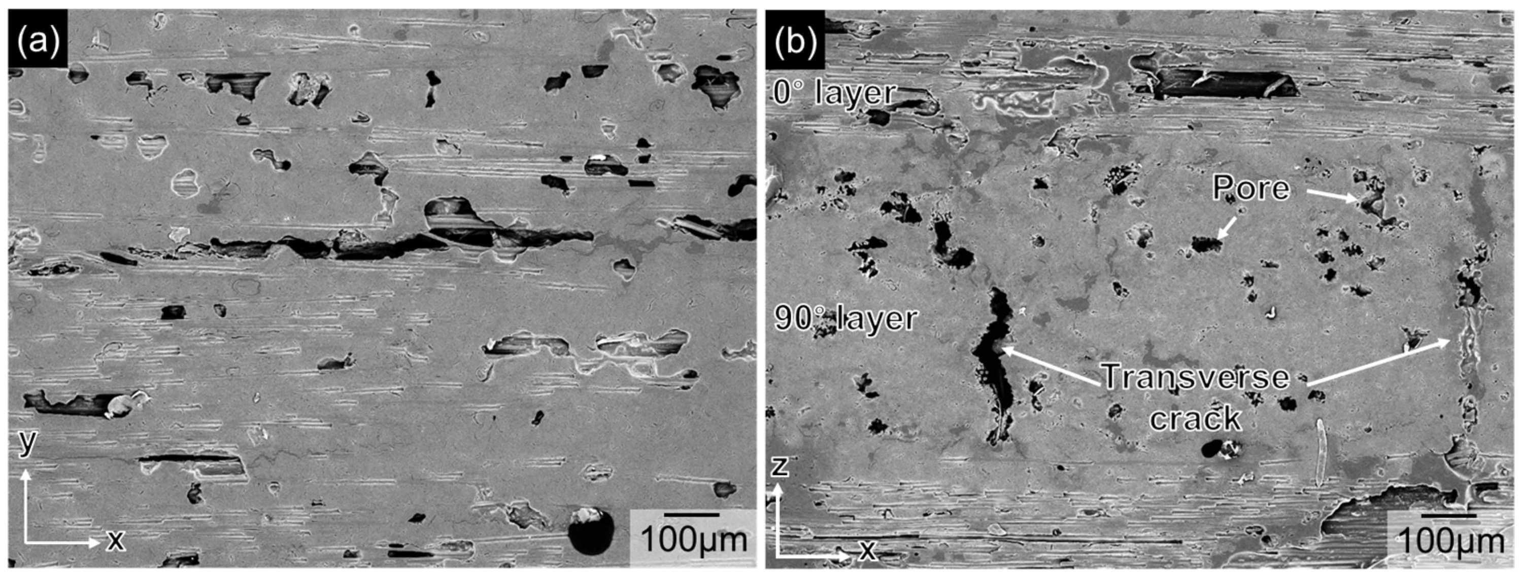
Figure 1. Typical microstructures of C/C preform: (a) in-plane direction, (b) through-the-thickness direction [50].
Jcs 09 00087 g001
Figure 2. Typical microstructures for prepared composites: (a) Z20, (b) Z36, and (c) Z80 [50].
Jcs 09 00087 g002
Figure 3. XRD analyses for prepared composites [50].
Jcs 09 00087 g003
Figure 4. Temperature profiles during the arc-wind tunnel test.
Jcs 09 00087 g004
Figure 5. The appearance of the surface after the arc-wind tunnel test: (a) C/C, (b) Z20, (c) Z36, and (d) Z80.
Jcs 09 00087 g005
Figure 6. The typical microstructures of the exposed surface obtained by SEM: (a) Z20, (b) Z36, and (c) Z80.
Jcs 09 00087 g006
Figure 7. The cross-sections of the composites with EDS mapping for the C, O, Zr, and Ti element after the arc-wind tunnel test: (a) Z20, (b) Z36, and (c) Z80.
Jcs 09 00087 g007
Figure 8. Relationship between the Zr content in the infiltrated alloy and the normalized thickness of the specimen (the circular symbols represent the plots of the test after 60 and 30 s, respectively) [50].
Jcs 09 00087 g008
Figure 9. Volatility diagram of the TiC-ZrC system at 2000 °C.
Jcs 09 00087 g009
Disclaimer/Publisher’s Note: The statements, opinions and data contained in all publications are solely those of the individual author(s) and contributor(s) and not of MDPI and/or the editor(s). MDPI and/or the editor(s) disclaim responsibility for any injury to people or property resulting from any ideas, methods, instructions or products referred to in the content.