Article

Development of Carbide-Reinforced Al-7075 Multi-Layered Composites via Friction Stir Additive Manufacturing

by
Adeel Hassan
1,2,*,
Khurram Altaf
2,
Mokhtar Che Ismail
1,2,*,
Srinivasa Rao Pedapati
3,*,
Roshan Vijay Marode
4,
Imtiaz Ali Soomro
5 and
Naveed Ahmed
6
1
Centre for Corrosion Research (CCR), Universiti Teknologi PETRONAS, Seri Iskandar 32610, Perak Darul Ridzuan, Malaysia
2
Department of Mechanical Engineering, Universiti Teknologi PETRONAS, Seri Iskandar 32610, Perak Darul Ridzuan, Malaysia
3
Department of Civil & Mechanical Engineering, College of Engineering & Sciences, The University of Texas Permian Basin, 11105 West Highway 191, Midland, TX 79707, USA
4
Department of Mechanical Engineering, Bajaj Institute of Technology, Wardha 442001, India
5
Interdisciplinary Research Center for Advanced Materials, King Fahd University of Petroleum and Minerals, Dhahran 31261, Saudi Arabia
6
Department of Industrial Engineering, College of Engineering, Al-Yamamah University, Riyadh 11512, Saudi Arabia
*
Authors to whom correspondence should be addressed.
J. Compos. Sci. 2025, 9(10), 568; https://doi.org/10.3390/jcs9100568
Submission received: 19 September 2025 / Revised: 11 October 2025 / Accepted: 14 October 2025 / Published: 15 October 2025

Abstract

Friction stir additive manufacturing (FSAM) is a promising solid-state technique for fabricating high-strength aluminum alloys, such as Al-7075, which are difficult to process using conventional melting-based additive manufacturing (AM) methods. This study investigates the mechanical properties and tool wear behavior of seven-layered Al-7075 multi-layered composites reinforced with silicon carbide (SiC) and titanium carbide (TiC) fabricated via FSAM. Microstructural analysis confirmed defect-free multi-layered composites with a homogeneous distribution of SiC and TiC reinforcements in the nugget zone (NZ), although particle agglomeration was observed at the bottom of the pin-driven zone (PDZ). The TiC-reinforced composite exhibited finer grains than the SiC-reinforced composite in both as-welded and post-weld heat-treated (PWHT) conditions, achieving a minimum grain size of 1.25 µm, corresponding to a 95% reduction compared to the base metal. The TiC-reinforced multi-layered composite demonstrated superior mechanical properties, attaining a microhardness of 93.7 HV and a UTS of 263.02 MPa in the as-welded condition, compared to 88.6 HV and 236.34 MPa for the SiC-reinforced composite. After PWHT, the TiC-reinforced composite further improved to 159.12 HV and 313.46 MPa UTS, along with a higher elongation of 11.14% compared to 7.5% for the SiC-reinforced composite. Tool wear analysis revealed that SiC reinforcement led to greater tool degradation, resulting in a 1.17% weight loss. These findings highlight the advantages of TiC reinforcement in FSAM, offering enhanced mechanical performance with reduced tool wear in multi-layered Al-7075 composites.

1. Introduction

Friction stir additive manufacturing (FSAM) has emerged as a promising solid-state approach for processing aluminum alloys that are difficult to fabricate through conventional melting-based additive manufacturing (AM) techniques. Among these alloys, Al-7075 is extensively used in the aerospace and automotive sectors because of its high strength-to-weight ratio [1,2]. This alloy belongs to the Al-Zn-Mg-Cu series, with Zn, Mg, and Cu as the main alloying elements. In fusion-based AM processes, the high-energy beam often causes Zn evaporation, which leads to significant solidification defects. Consequently, Al-7075 is generally regarded as non-fusion-weldable unless its composition is altered [1,3,4]. FSAM, a derivative of friction stir welding (FSW), was first reported in 2004 by White [5] and is classified under sheet lamination AM. In this process, feed plates of specified dimensions are consolidated below the melting point, as the joining occurs entirely in the solid state. Compared with fusion-based AM, FSAM offers a sustainable and cost-effective alternative, consuming nearly 2.5% of the energy and eliminating the requirement for vacuum or inert shielding chambers [6]. With a significantly lower heat flux (~103 W/m2 compared to ~107 W/m2) and higher deposition rates, FSAM is well-suited for large-scale production. Unlike melting-based AM processes, FSAM avoids fumes and CO2 emissions; it is forecasted that it potentially reducing up to 60 billion pounds of CO2 in the aerospace sector over 15 years [7,8]. Additionally, FSAM improves material efficiency with a buy-to-fly ratio as low as 3:1, making it both economical and environmentally friendly.
FSAM is still a new manufacturing technique, currently at technology readiness level 4, and has gained significant research interest in recent years [9]. Several studies [10,11,12,13,14,15,16,17,18,19] have been conducted on the FSAM of Al-6000 and 7000 series alloys. Although these studies provided fundamental insights into the FSAM processing of high-strength aluminum alloys, they primarily focused on unreinforced laminates, as shown in Table 1. Recently, S. Choudhury et al. [20] developed 15-layered Al-6061-T6/SiC-reinforced FSAM laminated composites using an H13 taper-threaded tool pin profile and incorporating 20 wt.% SiC. They reported a non-homogeneous microstructure and mechanical properties, where dynamic recrystallization (DRX) refined the nugget zone (NZ) grains, achieving uniform SiC dispersion with interparticle spacing down to 2 μm. However, repeated thermal exposure (static annealing) led to grain coarsening from the top to the bottom layers (5.93 μm < 6.18 μm < 6.84 μm). Microhardness varied along the build direction, ranging from 69.5 HV at the bottom to 104.2 HV at the top due to grain growth and precipitate coarsening. The top layer exhibited a UTS of 268.4 MPa with 39.4% elongation, whereas the bottom layer had a lower UTS of 233 MPa but exhibited higher ductility (58.98%).
M. Maurya et al. [21] incorporated 4 wt.% titanium carbide (TiC) and 6 wt.% grinding sludge (GS) to develop three-layered Al-6061-reinforced laminated composites using a high-speed steel (HSS) taper octagonal pin profile. The presence of hard TiC and GS particles in the aluminum matrix led to a 37.2% improvement in microhardness and a 25.8% enhancement in tensile strength. M. Srivastava et al. [22] developed six-layered Al-5059/SiC-reinforced FSAM laminated composites using a H13 heat-treated taper-threaded pin profile. They observed an uneven reinforcement distribution within the NZ due to improper process parameter selection, resulting in non-homogeneous microhardness along the build direction. Despite this, microhardness improved by approximately 62% compared to the base metal (BM). Similarly, A. Kumar et al. [23,24] investigated the mechanical properties of Al-7075 FSAM laminate reinforced with 4 wt.% zirconium oxide (ZrO2) and 0.6 wt.% graphene (G) using an HSS taper octagonal pin profile. They achieved a maximum microhardness of 87.4 HV and tensile strength of 286.5 MPa, highlighting the potential of reinforced composites via FSAM.
Table 1. Summary of the literature on FSAM studies indicating explored and unexplored research areas.
Base AlloyReinforcementMicrostructure
(Uniform)
Microhardness
(Uniform)
In Process CoolingTool WearPWHTReference
Al-6061-T6××××××[10]
Al-6061-T6××××××[11]
Al-6061-T6/
Al-7075-T6
××××××[12,25]
Al-6061-T6/
Al-5083-O/
Al-7075-T6
××××××[13]
Al-7075-O××××××[14]
Al-7N01-T4×××××[15]
Al-7075-T6××××××[16]
Al-7075-T6××××××[17]
Al-7075-T6×××××[18]
Al-7075-T6××[19]
Al-7N01-T4××[26]
Al-7075-T6×××[27]
Al6061-T6SiC××××[20]
Al6061-T6TiC, GS×××××[21]
Al-5059-OSiC×××××[22]
Al-7075-T6ZrO2/G×××××[23]
Al-7075-T6ZrO2/Gr×××××[24]
As summarized in Table 1, most previous FSAM studies have focused on fabricating aluminum alloy laminates without incorporating carbide reinforcements. Consequently, the microstructure and microhardness along the build direction remained non-uniform due to repeated thermal exposure under natural cooling conditions. Research specifically addressing the incorporation of carbide reinforcements such as SiC and TiC into Al-7075 multi-layered composites through FSAM remains limited. Although single-layer Al-7075 metal matrix composites reinforced with these carbides have been extensively investigated through friction stir processing (FSP) [28,29,30,31,32,33,34,35], their application in multi-layered FSAM introduces additional challenges. These challenges include achieving uniform particle dispersion and minimizing tool degradation. Tool wear is particularly critical in the FSAM of reinforced composites, as the abrasive nature of ceramic particles accelerates tool degradation with each subsequent layer. Therefore, it is essential to investigate the influence of carbide nanoparticle incorporation on the microstructural evolution, mechanical behavior, and tool wear characteristics of FSAM-fabricated multi-layered composites.
This study aims to address these research gaps by investigating the FSAM of carbide-reinforced Al-7075 multi-layered composites. The mechanical properties, including tensile strength, microhardness, and elongation, are evaluated to assess the influence of SiC and TiC reinforcements. Tool wear is systematically analyzed through dimensional analysis and weight loss assessments to understand the impact of reinforcement on tool degradation. Furthermore, post-welding heat treatment (PWHT) is employed to enhance the microstructural and mechanical performance of the fabricated composites. The primary contribution of this work lies in establishing a comparative understanding of SiC and TiC reinforcements in relation to the microstructure–property relationship and tool wear behavior during the FSAM of Al-7075. This comparative evaluation fills a critical research gap by linking reinforcement selection to process efficiency, tool life, and performance optimization. The findings of this study contribute to the development of lightweight, high-performance structural materials for aerospace and automotive applications.

2. Materials and Methods

2.1. Feed Material Preparation and FSAM

In the present work, Al-7075-T651 plates with a thickness of 6.35 mm were utilized as a feed material, while SiC and TiC nanoparticles were introduced as reinforcements. SiC particles ranged from 200 nm to 2 µm, while TiC nanoparticles measured between 40 nm and 600 nm. Two multi-layered SiC- and TiC-reinforced composites, each consisting of seven layers, were fabricated using the FSAM process. Prior to FSAM, the SiC- and TiC-reinforced feed plates were prepared. A 5 vol.% reinforcement powder was introduced into pre-machined grooves on the plates. This percentage was finalized after preliminary trials, where higher reinforcement levels (10–15 vol.%) led to tool pin fracture due to increased resistance. Accordingly, the groove dimensions of 110 × 2 × 1.6 mm (length × width × depth) were calculated using standard Equations (1)–(3) [20] based on the 5 vol.% powder requirement and machined along the plate centerline.
Volume   fraction   V f = a r e a   o f   g r o o v e   ( A g ) P r o j e c t e d   a r e a   o f   t o o l   p i n   ( A p )
Ag = groove width × groove depth
Ap = pin diameter × pin length
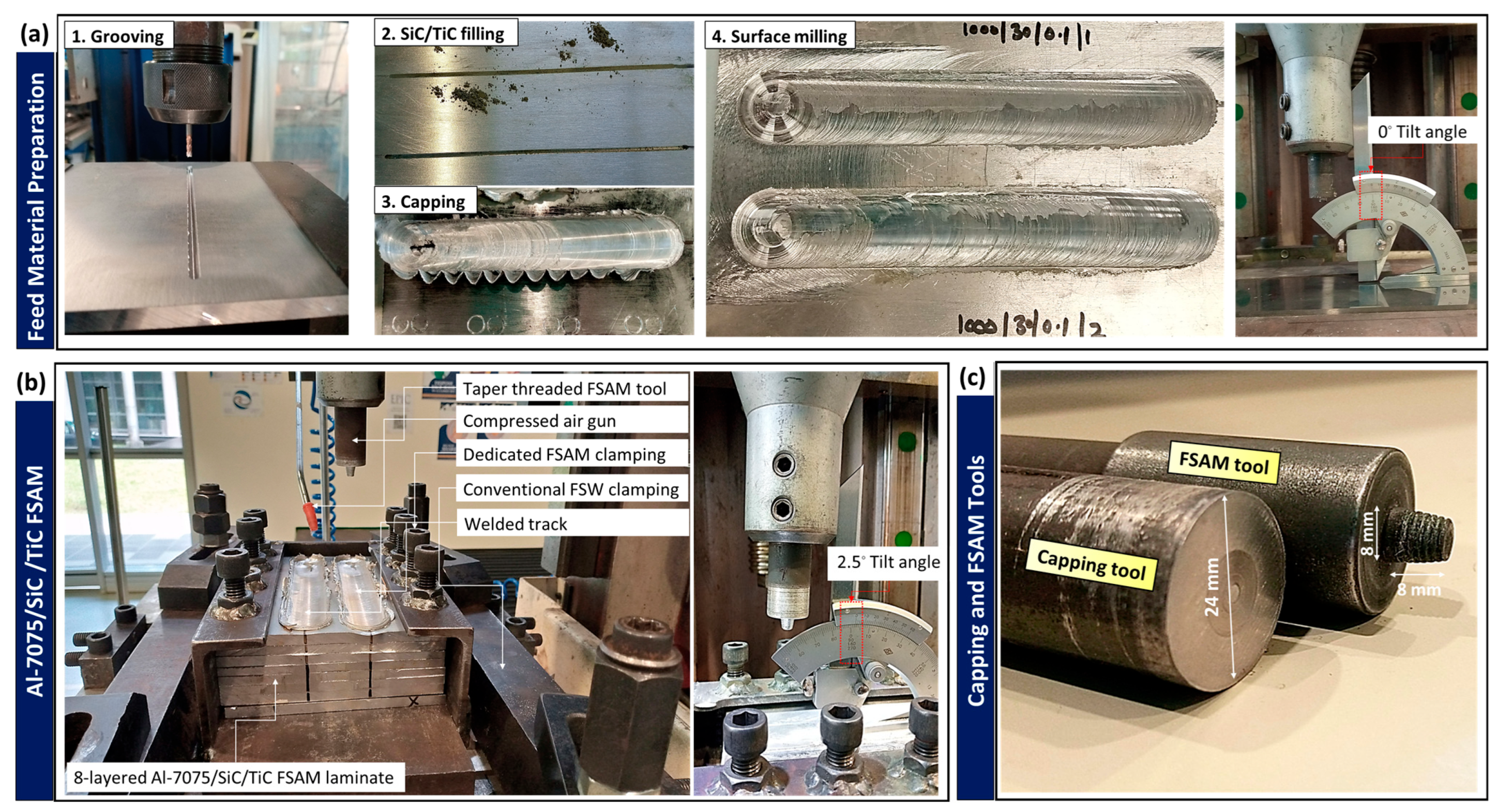
The grooves were filled with powder particles and manually compacted. Subsequently, the grooves were capped using an H13 pin-less tool with a 24 mm shoulder diameter at a tool rotational speed (TRS) of 1000 rpm and a tool traverse speed (TTS) of 20 mm/min, with a zero-degree tool tilt angle and a 0.2 mm shoulder plunge depth. The flash generated during capping was removed using a milling operation to achieve a smooth surface for FSAM. Schematic illustrations and actual experimental setups of the feed plate preparation are shown in Figure 1a and Figure 2a, respectively. For FSAM, the TRS and TTS were set at 1000 rpm and 20 mm/min, respectively, with a pin plunge depth of 0.3 mm, a tilt angle of 2.5°, and double tool passes in the same counter-clockwise direction. These machine parameters were finalized after preliminary trials, during which lower TRS and higher TTS resulted in tool pin fracture due to insufficient heat generation and inadequate material plasticization. A taper-threaded tool pin profile, 8 mm in length with a tip-to-root diameter of 6 mm to 8 mm, was used [16]. A comprehensive set of FSAM parameters is listed in Table 2. Throughout the process, compressed air was applied to the composites to enhance cooling. The air, maintained at a pressure of 6 bar, was delivered through an air blow gun positioned 210 mm from the starting edge. The airflow across the exposed composite surfaces reached 11,550 m3/h with a velocity of 16.3 m/s, as measured using a TESTO-440 (ComboKit) multipoint flow meter. The complete FSAM process and actual experimental setup are illustrated in Figure 1 and Figure 2.

2.2. Sample Preparation and PWHT

After fabricating the multi-layered reinforced composites, rectangular cross-sectioned samples were extracted from the as-welded composites in the build direction for microstructural assessment, microhardness investigations, and sub-sized tensile testing. These samples comprised the NZ of each layer. PWHT was applied to investigate its effect on microstructural and mechanical behavior. The treatment consisted of cyclic solutionizing at 400 °C and 480 °C for 15 min per cycle, for a cumulative duration of 1.5 h, followed by water quenching and subsequent aging at 130 °C for 24 h [19]. Prior to microstructural investigation, the samples were ground and polished, followed by chemical etching using Keller’s reagent for 18 s.

2.3. Microstructure and Mechanical Testing

Grain size measurements were conducted using optical microscopy (OM) at 50x and 100x magnifications. A total of 50 grains per sample were measured to determine the average grain size. To analyze second-phase strengthening precipitates, a field emission scanning electron microscope (FESEM) coupled with energy dispersive X-ray spectroscopy (EDX) was used. The fracture surfaces of tensile specimens were examined with a scanning electron microscope (SEM). Microhardness was evaluated along the building direction from the bottom to the top layer with 0.5 mm spacing at room temperature under a 500 gf load. Tensile testing was performed following ASTM E8 standards at a strain rate of 0.1 mm/s using a Zwick 50 kN universal tensile testing machine. Both SiC- and TiC-reinforced composites were evaluated in the as-welded and PWHT conditions for microstructural and mechanical properties. To ensure data reliability, three samples were tested for each condition, and the average tensile strength and elongation values were reported along with standard deviations. Tool wear analysis was conducted using dimensional analysis through OM, along with weight loss measurements using a digital weighing machine with a sensitivity of ±0.001 g.

3. Results and Discussion

3.1. Microstructure

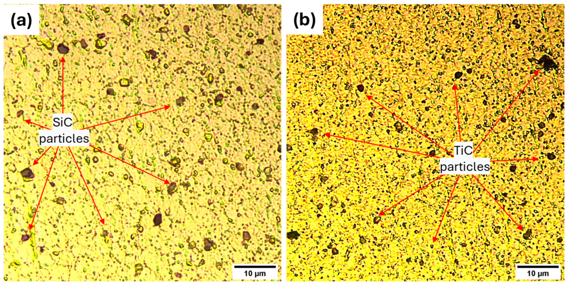
Major challenges of volumetric defects were successfully addressed by adjusting machine parameters, such as TRS, TTS, and plunge depth. The cross-sections of Al-7075/SiC and Al-7075/TiC composites, as depicted in Figure 3, show no volumetric defects, indicating improved material mixing. However, on a microscopic level at the bottom of the pin-driven zone (PDZ), reinforcement particles clustered leading to agglomeration. The EDX and color elemental mapping at the bottom of the PDZ for both composites are illustrated in Figure 4 and Figure 5. In Figure 4, it can be seen that SiC particles are very large and not fully broken, while in Figure 5, TiC particles are similarly clustered and also large. In contrast, in the middle of each NZ, SiC and TiC particles are more homogeneously dispersed, as shown in Figure 6. The taper-threaded pin design may have contributed to the particle clustering and agglomeration observed at the bottom of the PDZ due to its impact on material flow, shear force distribution, and stirring intensity. Near the bottom of the PDZ, the stirring action may not have been strong enough to adequately mix the particles, leading to incomplete particle mixing and resulting agglomeration [30,36]. This agglomeration can be mitigated by using a plain cylindrical pin profile instead of a taper-threaded one and employing the blind hole method rather than the continuous groove for particle incorporation, along with optimized TRS and TTS [37,38].
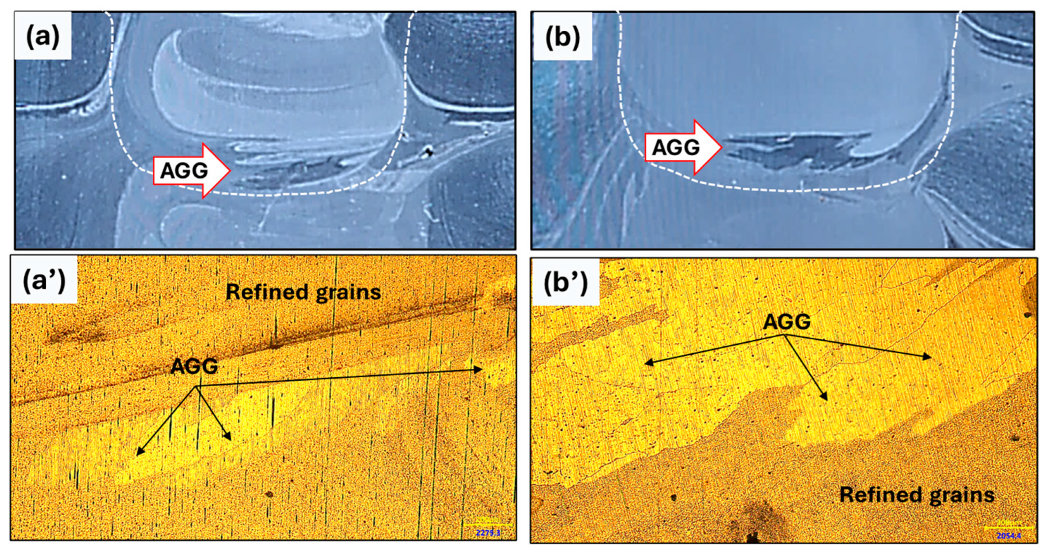
Figure 7 illustrates the average grain size obtained for the composites in the as-welded and PWHT-treated states. In the as-welded state, the SiC-reinforced composite exhibited an average grain size of 2.14 µm, while the TiC composite showed a finer grain size of 1.25 µm. This difference is attributed to the smaller TiC particles compared to the SiC particles after processing. The smaller TiC particles, located at the grain boundaries, act as obstacles to grain growth due to their stronger pinning effect, thereby preventing coarsening. After PWHT, grains in both composites coarsened slightly to 2.30 µm for the SiC-reinforced composite and 1.30 µm for the TiC-reinforced composite, which is expected due to grain growth. During solution treatment, recrystallization and grain growth occurred as high temperatures enabled atomic rearrangement into stable states, causing smaller grains to merge into larger ones. Aging promoted precipitate formation and stabilization, though extended exposure led to further coarsening [39]. After PWHT, abnormal grain growth (AGG) appeared at the bottom of the PDZ+PDZ region in both composites. This was linked to thermal instability in the nugget zone (NZ), where ultrafine grains were consumed and η-phase precipitates dissolved, creating precipitate-free zones (PFZ), as shown in Figure 8 [40,41]. Temperature gradients along the tool pin introduced variations in stored strain energy and grain size. Together with reduced boundary pinning from precipitate dissolution, this favored AGG development during PWHT, in agreement with the Humphreys cellular model and other reports [42,43,44,45]. Similar AGG behavior has also been observed in the PWHT of FSW-processed 2024, 6061, and 7075 alloys.
A very high TRS and the consequently rapid stirring action resulted in fairly dispersed SiC and TiC particles within the NZ. EDX and corresponding color elemental mapping of the NZ for both SiC and TiC composites are depicted in Figure 9 and Figure 10. EDX spectra 14 and 15, respectively, show peaks for Si, Ti, and C, indicating the presence of SiC and TiC within the Al matrix, as supported by color elemental mapping. Notably, SiC and TiC particles cover a large surface area, as demonstrated in the color elemental mapping, which reveals a homogeneous dispersion of SiC and TiC in both composites, with no agglomeration. Furthermore, other alloying elements of Al-7075 were also homogeneously dispersed, indicating efficient mixing of the SiC and TiC particles with the aluminum matrix.
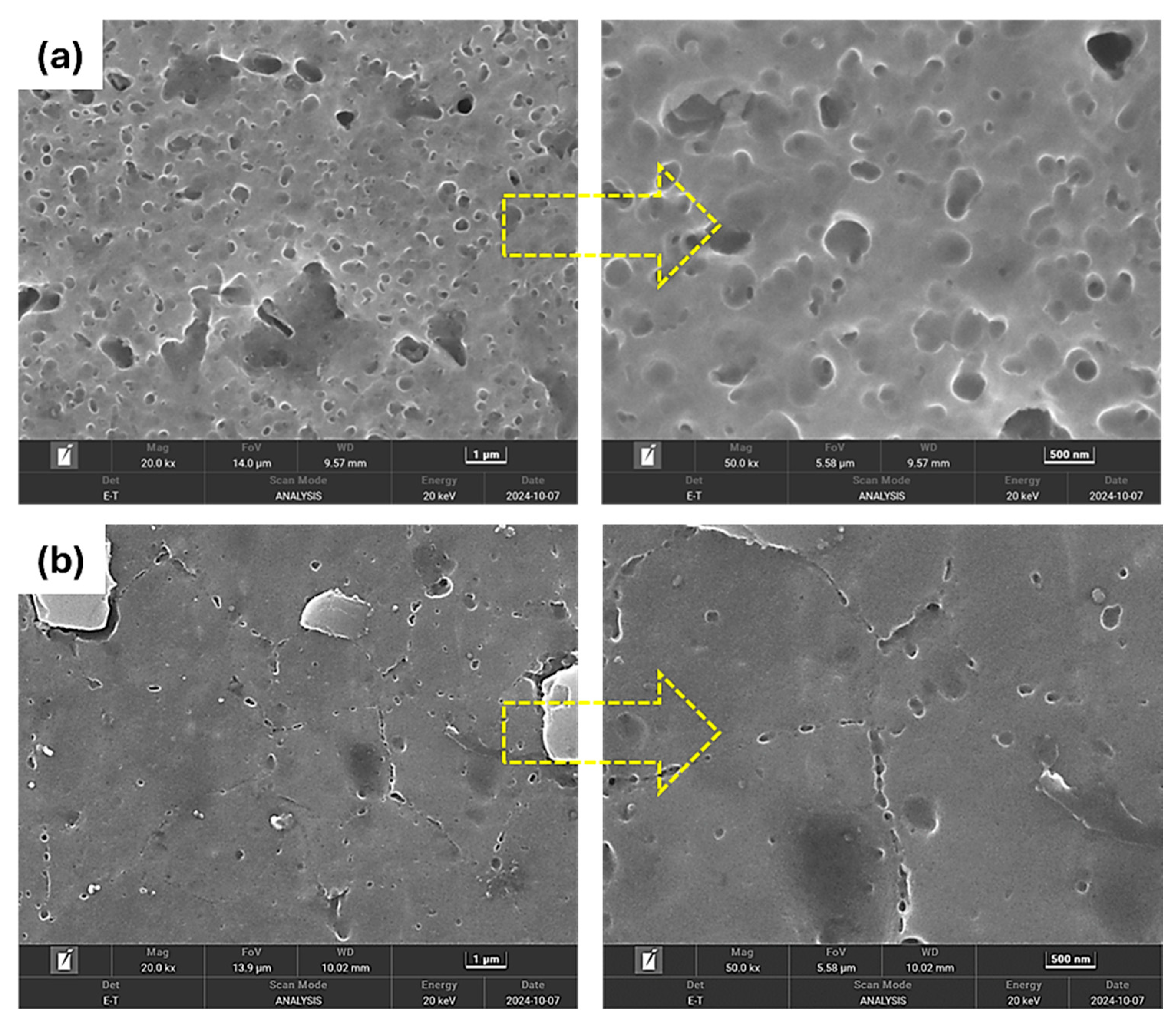
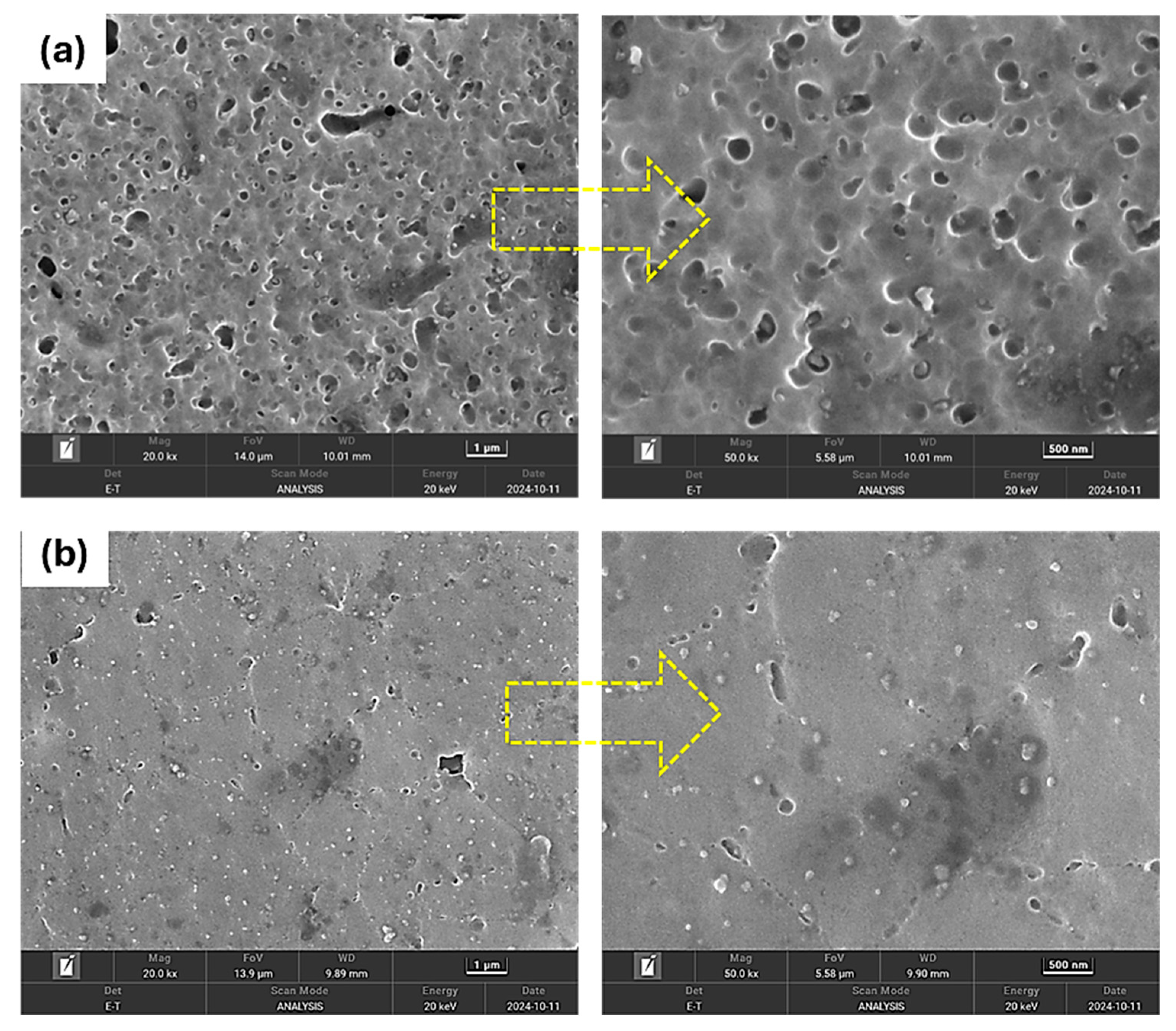
Figure 11 and Figure 12 present the FESEM images at 20 kx and 50 kx magnification of Al-7075/SiC and Al-7075/TiC composites, highlighting second-phase strengthening precipitates. In Figure 11a, the inherent precipitates in the SiC composite were observed to be coarsened and overaged, measuring approximately 110 ± 66 nm in the as-welded state. In contrast, precipitates in the TiC composite (Figure 12a) measured 85 ± 45 nm. These strengthening precipitates were overaged due to excessive heat generated by the high TRS of 1000 rpm, TTS of 20 mm/min, and PD of 0.3 mm, even though high TRS facilitates better dispersion of the reinforced particles [46]. Notably, the size difference in strengthening precipitates between these two composites can be attributed to the nature of the reinforcements. SiC particles are more abrasive than TiC particles, generating greater frictional heat due to intense mechanical interaction. Additionally, SiC exhibits significantly higher thermal conductivity (490 W/mK) [47,48,49] than TiC (36.4 W/mK) [50], facilitating rapid heat dissipation into the aluminum matrix. This increased heat absorption by the aluminum matrix ultimately leads to greater heat development in the Al-7075/SiC composite. Consequently, this higher heat development results in larger second-phase strengthening precipitates in the SiC-reinforced composite compared to the TiC-reinforced composite. Although 5 vol.% of SiC and TiC were incorporated and acted as obstacles to grain growth through the pinning effect, in heat-treatable aluminum alloys like Al-7075-T6 and Al-6061-T6, primary contributors to mechanical properties are the strengthening precipitates, which play a more dominant role than grain size [46].
After cyclic solution treatment followed by aging at 130 °C, the precipitates redissolved into the aluminum matrix and subsequently reprecipitated, forming a fine and uniform distribution both inside the grains and along the grain boundaries, as illustrated in Figure 11b and Figure 12b. These precipitates were significantly finer compared to the as-welded state, measuring approximately 53.6 ± 16 nm in the SiC-reinforced composite and 42.65 ± 14 nm in the TiC-reinforced composite, respectively. This refinement contributed to enhanced mechanical properties.

3.2. Microhardness

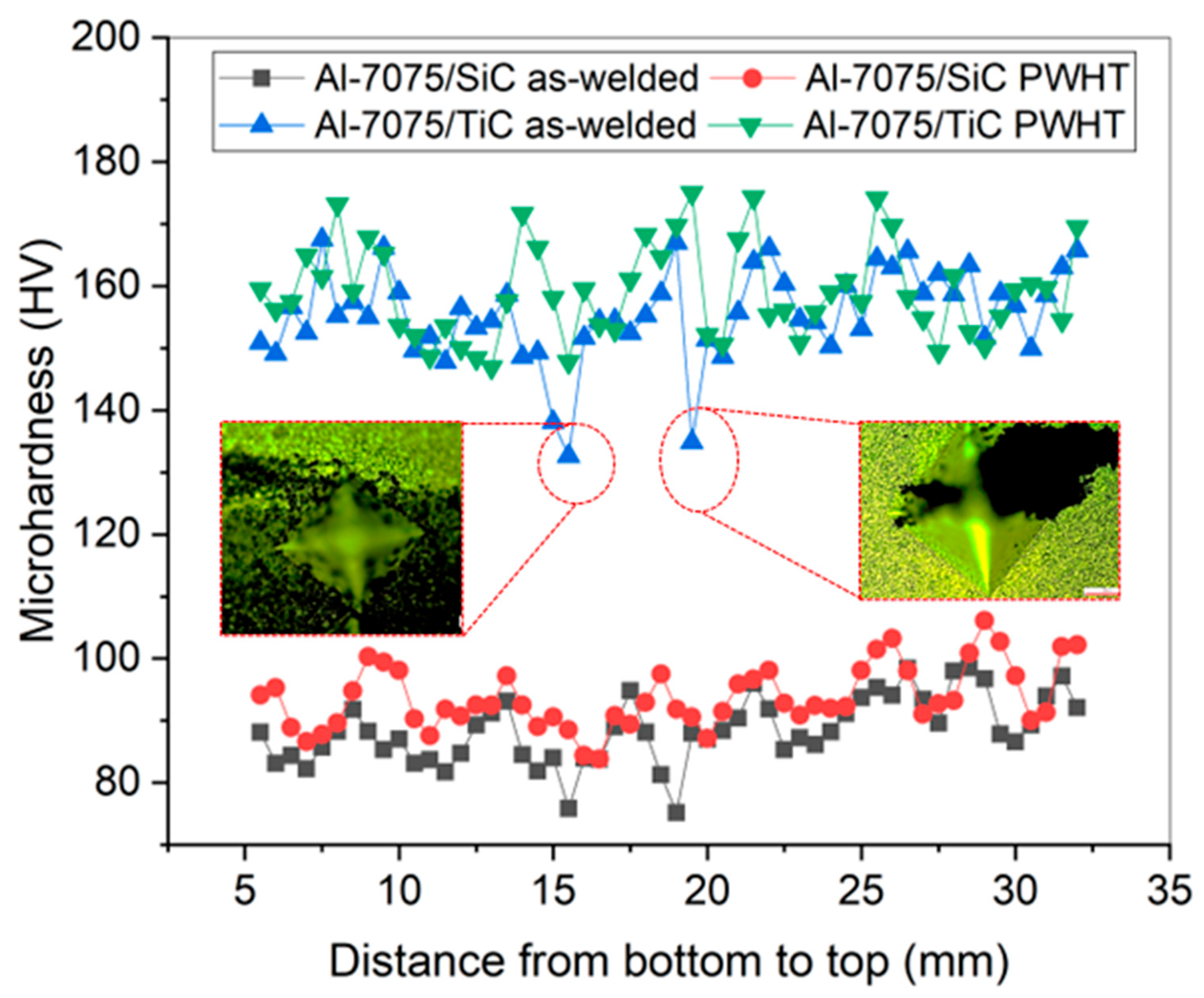
Microhardness profiles of both Al-7075/SiC- and Al-7075/TiC-reinforced composites, before and after PWHT, are shown in Figure 13. Continuous forced cooling during processing effectively controlled static annealing and contributed to uniform microhardness across the fabricated composites by maintaining lower peak temperatures and reducing thermal exposure time. In contrast, previous studies [13,14,15,16,20,21,23] that employed natural cooling at room temperature reported a linear increase in microhardness from the bottom to the topmost layer due to repeated exposure to elevated temperatures during successive passes. However, localized reductions in microhardness were observed in certain PDZ regions, primarily due to the agglomeration of SiC and TiC particles. Such agglomeration led to inadequate bonding with the aluminum matrix, resulting in porosity and interparticle gaps at the microscale [46], which caused incomplete impressions from the microhardness indenter, as shown in Figure 13.
The average microhardness of the SiC-reinforced composite was 88.6 HV, while the TiC-reinforced composite reached 93.7 HV, representing 50.6% and 53.5% of the BM, respectively. These values align with the lower microhardness observed in sample L7, which had no reinforcement [27]. However, the average grain sizes of the SiC and TiC composites were 2.14 µm and 1.25 µm, respectively, showing nearly a 95% reduction compared to the BM as a result of DRX. The microhardness of heat-treatable aluminum alloys such as Al-7075-T6 and Al-6061-T6 is not governed by grain size alone but also depends on the morphology of second-phase strengthening precipitates that significantly influence hardness. The overaging and excessive dissolution of these precipitates leads to a reduction in microhardness. The high TRS of 1000 rpm, combined with a TWS of 20 mm/min, generated excessive heat during processing, leading to material softening and promoting the dissolution and overaging of strengthening precipitates within the aluminum matrix. This heat buildup, along with the limited presence of 5 vol.% reinforcement particles, resulted in a dominant aluminum matrix with reduced microhardness. These processing parameters were chosen to ensure proper dispersion of reinforcement particles and effective bonding with the aluminum matrix. However, the relatively low percentage of reinforcement, combined with excessive softening from the high heat input, contributed to the overall lower microhardness in the as-welded state. A similar reduction in microhardness after the addition of 20 wt.% SiC particles in Al-6061-T6 FSAM composite was reported in a study by S. Choudhury et al. [20]. The loss of microhardness in that study was also attributed to the dissolution of strengthening precipitates of heat-treatable aluminum alloys during the FSAM process [51,52].
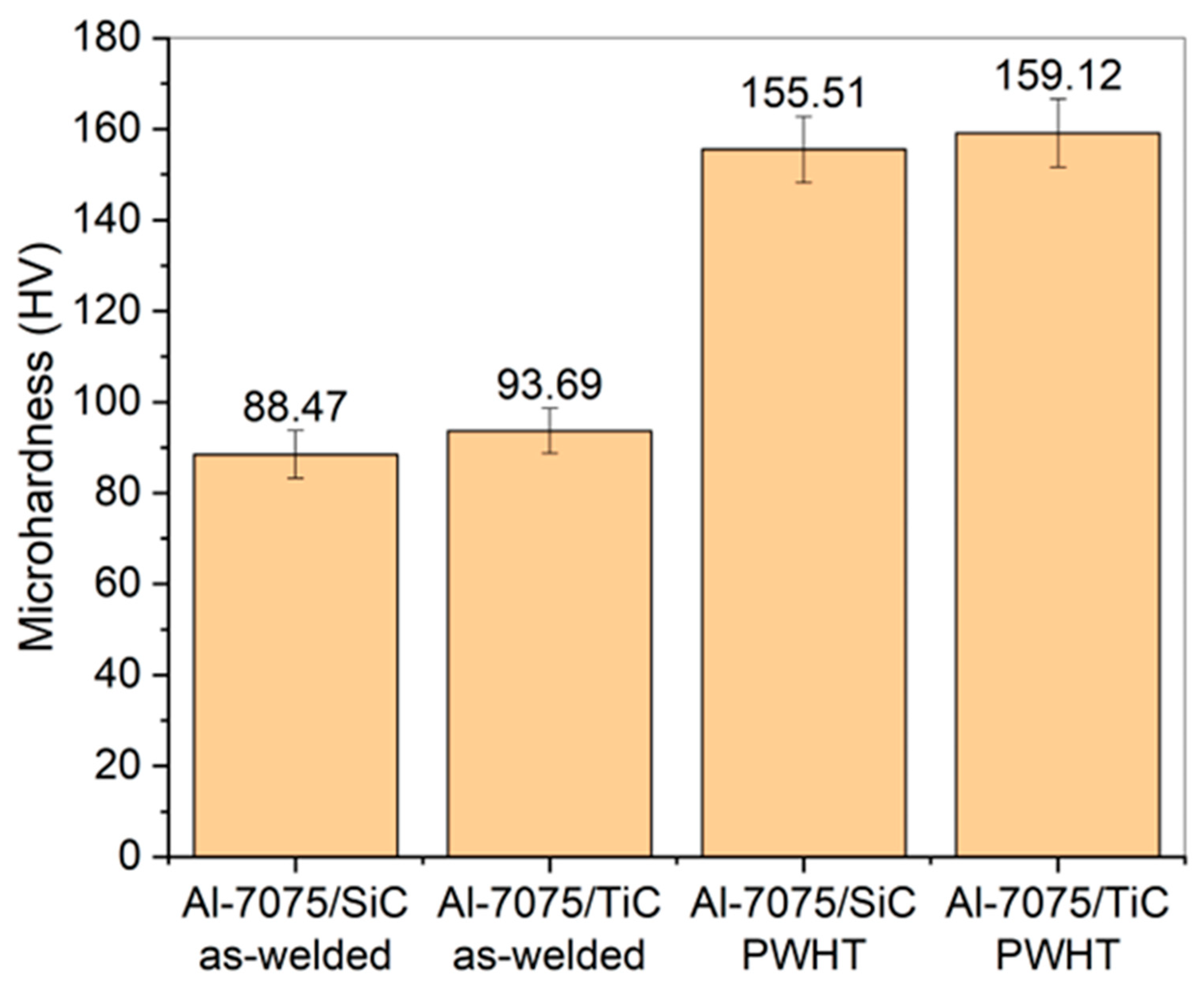
After PWHT, the microhardness of both composites increased notably, reaching 155.5 HV for the SiC composite and 159 HV for the TiC composite, as shown in Figure 14. These values are close to the BM microhardness (175 HV). The improvement is attributed to the reprecipitation and uniform dispersion of aluminum-strengthening precipitates that had coarsened during FSAM. This refined and homogeneous distribution of precipitates after PWHT can be seen in Figure 11 and Figure 12, which demonstrates microstructural recovery within the aluminum matrix and contributes to enhanced overall hardness. The TiC-reinforced composite exhibited a higher hardness of 159 HV, exceeding the values (90–130 HV) reported for Al-7075/ZrO2/Gr, Al-7075/Al2O3, and Al-7075/TiC composites fabricated through FSAM and AFSD [23,24,53,54].

3.3. Tensile Properties

Figure 15 depicts the stress–strain plots for both as-welded and PWHT-treated Al-7075/SiC and Al-7075/TiC composites. The Al-7075/SiC samples fractured at the interface between the fifth and sixth layers, while the Al-7075/TiC samples fractured between the fourth and fifth layers. In both cases, the agglomeration of reinforcement particles at these interfaces created weak bonding zones that served as premature fracture under tensile loading. The stress–strain curves indicate limited plastic deformation, suggesting predominantly brittle fracture behavior. The Al-7075/SiC composite exhibited a UTS of 236.34 MPa, whereas the Al-7075/TiC composite achieved a higher UTS of 263.02 MPa. This improvement in the TiC-reinforced composite is attributed to stronger particle–matrix interfacial bonding, a more uniform distribution of reinforcement particles, and finer grains and strengthening precipitates, as discussed in the microstructural analysis. The corresponding fracture morphologies are shown in Figure 16 and Figure 17.
In the SiC composite (Figure 16), the fracture surface reveals widespread clusters of SiC particles appearing as dark grey regions, indicating poor interfacial bonding with the aluminum matrix. Only a few isolated light grey regions exhibit better bonding. SEM magnification confirms that clustered SiC regions weaken the matrix–particle interface, promoting crack initiation and premature failure. Conversely, the limited well-bonded regions display shallow dimples (Figure 16a), reflecting localized plastic deformation that accounts for the measured elongation of 7.5%. However, due to the dominance of poorly bonded clusters, the composite exhibits early fracture and low ductility.
In contrast, the TiC-reinforced sample (Figure 17) exhibits a fracture surface where approximately 60% of the gauge area is clustered with TiC particles, which appear as dark regions, while the remaining 40% of the gauge area, represented by light grey regions, indicates better bonding between TiC particles and the aluminum matrix. Magnified images reveal that the regions with better TiC-Al matrix bonding (light grey) exhibit fine dimples on the fracture surface (Figure 17a). These regions also show smaller TiC particles, indicating effective bonding and ductile fracture behavior. In contrast, regions where TiC particles are clustered (Figure 17b) show poor bonding, leading to stress concentration zones that contribute to premature failure.
PWHT partially recovered strength by reprecipitating and stabilizing the strengthening phases in the aluminum matrix. Nevertheless, reinforcement agglomeration persisted, leading to premature fracture. Additionally, AGG observed after PWHT (Figure 8) further limited strength improvement. The average UTS increased from 236.34 MPa (SiC) and 263.2 MPa (TiC) in the as-welded condition to 286.49 MPa and 313.46 MPa, respectively, after PWHT, as shown in Figure 15. Overall, the TiC-reinforced composite achieved 56% of the BM UTS, while the SiC-reinforced composite attained 51.15%. A similar reduction in strength after the addition of 20 wt.% SiC particles in the Al-6061-T6 FSAM composite was reported in a study by S. Choudhury et al. [10,20], where the material exhibited excellent bonding and even dispersion. Interestingly, no significant improvement in UTS was observed compared to the Al-6061-T6 composite fabricated without SiC reinforcement. In contrast, the tensile strength results of the present study exceeded the values (250–280 MPa) reported for Al-7075/ZrO2/Gr and Al-7075/TiC composites fabricated through FSAM and AFSD [23,24,54].
Despite improved strength, ductility remained nearly unchanged after PWHT. This retention in elongation results from balanced microstructural evolution, where cyclic solution treatment promotes uniform solute distribution and stress relief, while aging at 130 °C for 24 h forms fine precipitates that strengthen the matrix without severely restricting dislocation motion. AGG occurs after PWHT, as shown in Figure 8, also contributes to maintaining ductility by enabling strain accommodation through larger grains [19,39].

3.4. Tool Wear Analysis

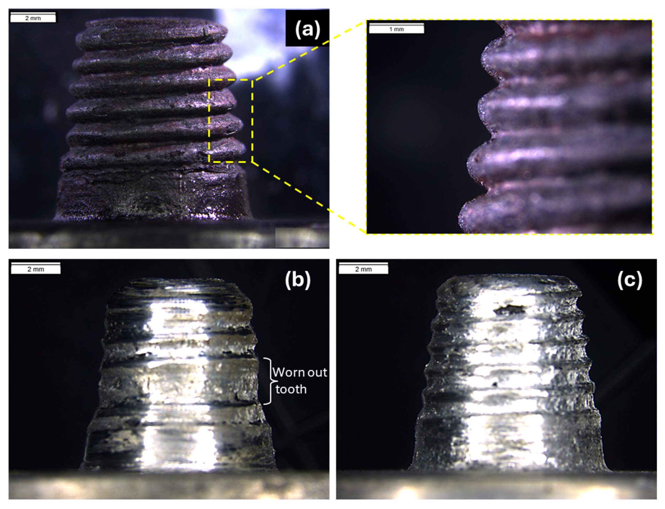
Tool wear is a critical challenge during the fabrication of carbide-reinforced Al-7075 FSAM composites. Tool wear is influenced by multiple factors, including TRS, TTS, PD, tool pin geometry, tool material, amount of reinforcement, and method of nanoparticle addition [46], which ultimately affect the FSAM composite quality. Figure 18 shows macrographs of FSAM tools before and after processing. The tool pin, which initially had sharp teeth, experienced substantial wear after processing, particularly in the case of the SiC-reinforced composite. In contrast, TiC composite showed much less wear. This difference is due to both the physical and chemical characteristics of the reinforcement materials. SiC, with a Mohs hardness of ~9.5, is highly abrasive [55], leading to mechanical erosion of the tool surface during FSAM. The tool wear in the SiC composite was excessive, with one complete tooth worn out and a notable reduction in pin tip diameter and length as shown in Figure 18b, resulting in a total weight loss of 2.7 g (1.17% weight loss) after completing the eight-layered Al-7075/SiC composite. On the other hand, TiC, with a Mohs hardness of ~9 [56,57], is less abrasive than SiC, which results in less tool wear. The pin tip diameter decreased slightly, and pin length remained nearly unchanged, with a weight loss of 1.25 g (0.54% weight loss).
Dimensional analysis and weight loss data (as shown in Table 3) confirm that SiC particles result in greater tool wear than TiC under the same FSAM parameters. The significant wear observed can be attributed to the combined effects of mechanical erosion caused by the high hardness of SiC and its chemical reactivity with the tool material (H13 steel). SiC reacts with iron at high temperatures, forming brittle compounds like iron silicide (FeSi) and iron carbide (Fe3C) at the tool surface. These reactions weaken the tool, making it more prone to wear and material removal, especially under the high temperature generated in FSAM processing, particularly at high TRS and low TTS. In contrast, TiC exhibits lower abrasiveness and is chemically more stable compared to SiC when interacting with iron-based tools [56]. Its chemical stability minimizes significant reactions with the tool material, leading to a reduced wear rate, as evident from the dimensional analysis and weight loss measurements in Table 3.
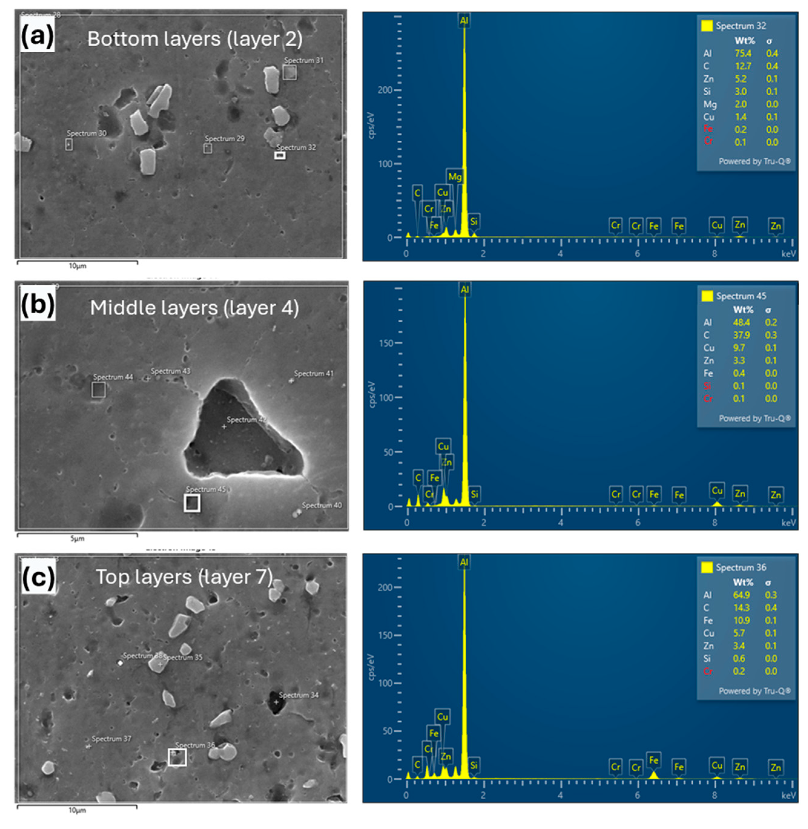
Furthermore, to validate the dimensional analysis, EDX was performed on the bottom, middle, and top regions of the SiC-reinforced composite. The EDX data for spot 32 (bottom), spot 45 (middle), and spot 36 (top), as shown in Figure 19, confirm the presence of iron (Fe), indicating tool wear throughout the process. At the bottom (spot 32), Fe content was 0.2%, which increased to 0.4% in the middle (spot 45) and reached 10.9% at the top (spot 36). Initially, with a fresh tool, the wear rate was minimal, resulting in low Fe content in the bottom layers. However, significantly higher Fe content in the top layers reflects increased tool degradation due to continuous interaction with SiC particles, exacerbating tool wear [20]. Ultimately, one complete thread of the tool pin, as shown in Figure 18, was worn out, and the tool experienced a weight loss of 1.17% by the end of the eight-layered SiC-reinforced composite’s fabrication.
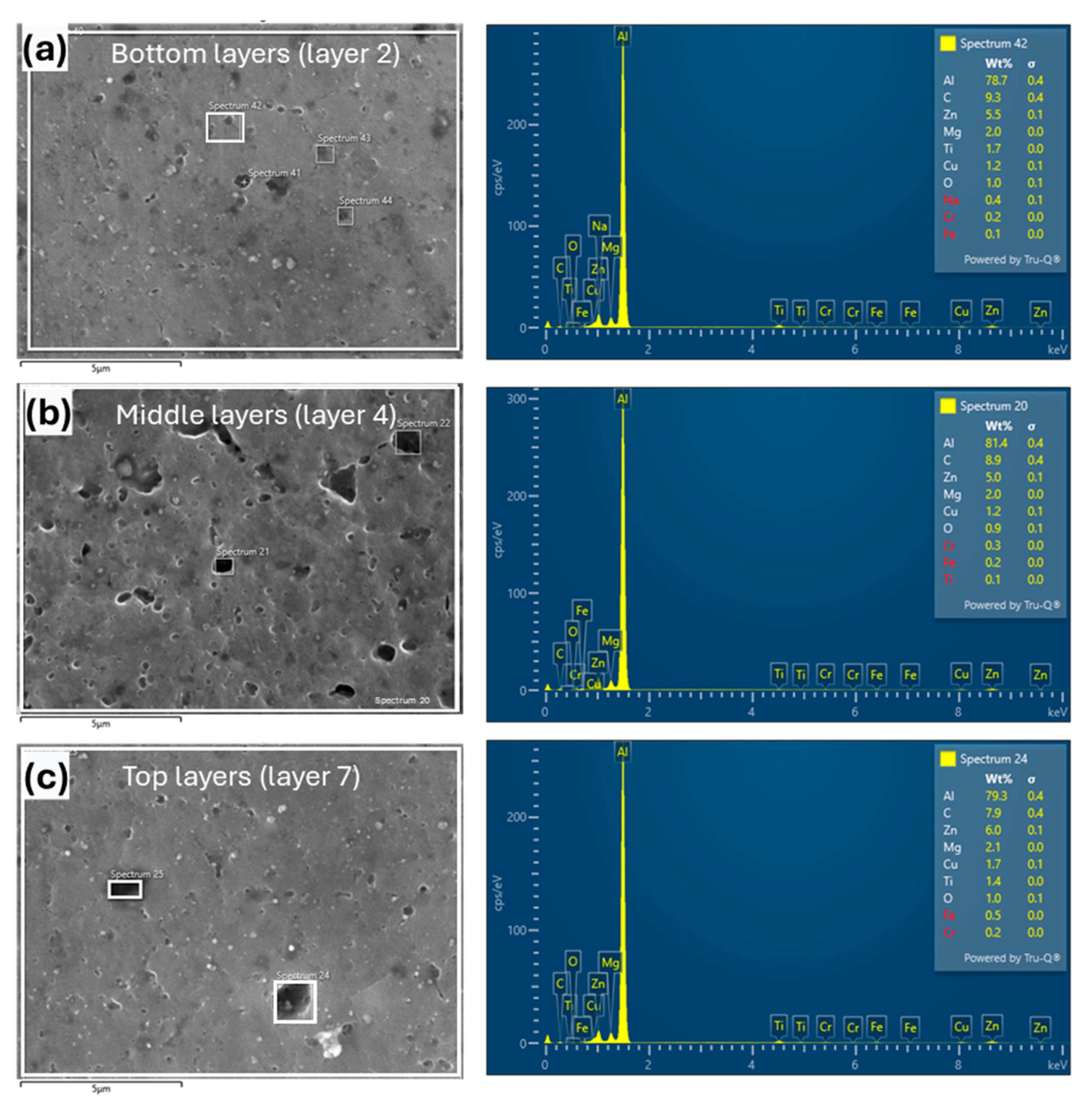
Similarly, EDX analysis was conducted to assess tool wear in the TiC-reinforced composite, as shown in Figure 20. In the bottom layers, the Fe content was very low at 0.1%, while in the middle it increased slightly to 0.2%. At the top, the wear rate was higher but still relatively low, with 0.5% Fe. In comparison to the SiC-reinforced composite, Fe content at the top in the TiC composite was much lower, indicating significantly less tool wear. This is further supported by Figure 18, which indicates that the tool used for the TiC composite remained in good condition, with sharp teeth, unlike the tool used for SiC, which showed significant wear.
In the present study, a high TRS combined with a low TWS was employed, resulting in elevated heat generation and enhanced material flow. This combination of parameters was not primarily responsible for tool wear, as elevated temperature results in a higher degree of DRX that helped to minimize tool degradation [58]. Therefore, the choice of tool material and the method of reinforcement incorporation are critical for controlling the tool wear rate.

4. Conclusions

Seven-layered carbide-reinforced Al-7075 composites were successfully fabricated using the FSAM process to study the influence of SiC and TiC reinforcements on mechanical properties and tool wear. The key inferences derived from the present investigation are as follows:
  • Microstructural characterization revealed defect-free composites with uniformly distributed reinforcements and fine equiaxed grains generated through DRX; however, slight particle agglomeration was noted near the bottom of the PDZ.
  • Reinforcement with TiC led to a significantly refined grain structure under both as-welded and PWHT conditions, achieving a minimum grain size of 1.25 µm and nearly a 95% reduction relative to the BM.
  • Composites containing TiC displayed enhanced mechanical properties, recording a peak microhardness of 159.12 HV, tensile strength of 313.46 MPa, and elongation of 11.14%, outperforming those reinforced with SiC.
  • Tool wear analysis indicated that SiC reinforcement induced greater tool degradation (1.17% weight loss), while TiC resulted in lower wear (0.54%), contributing to improved tool stability. These findings highlight the suitability of TiC for multi-layer FSAM applications, enhancing tool life, process consistency, and overall cost-efficiency for industrial implementation.
Future work should focus on optimizing tool materials, applying protective coatings, and improving reinforcement incorporation methods to minimize tool wear and ensure uniform nanoparticle distribution. Advanced characterization techniques, such as EBSD analysis, are also recommended to better understand grain boundary evolution and texture development. These efforts will further enhance the process capability and broaden the potential applications of FSAM in the aerospace and automotive sectors.

Author Contributions

Conceptualization, A.H., K.A., M.C.I. and S.R.P.; methodology, A.H., S.R.P. and R.V.M.; software, I.A.S. and N.A.; validation, A.H., K.A. and M.C.I.; formal analysis, A.H., K.A. and N.A.; investigation, A.H., S.R.P., R.V.M. and I.A.S.; resources, K.A. and M.C.I.; data curation, A.H. and R.V.M.; writing—original draft preparation, A.H.; writing—review and editing, A.H., S.R.P., R.V.M. and N.A.; visualization, I.A.S. and N.A.; supervision, K.A., M.C.I. and S.R.P.; project administration, K.A. and M.C.I.; funding acquisition, M.C.I. All authors have read and agreed to the published version of the manuscript.

Funding

This research received no external funding.

Institutional Review Board Statement

Not applicable.

Data Availability Statement

The original contributions presented in this study are included in the article. Further inquiries can be directed to the corresponding authors.

Acknowledgments

The authors would like to acknowledge Universiti Teknologi PETRONAS, Malaysia, for providing financial support to publish this work under Grant No. MRA 015NDO-225.

Conflicts of Interest

The authors declare no conflicts of interest.

References

  1. Kvvssn, V.; Butt, M.M.; Laieghi, H.; Uddin, Z.; Salamci, E.; Kim, D.B.; Kizil, H. Recent Progress in Additive Manufacturing of 7XXX Aluminum Alloys; Springer: London, UK, 2025; Volume 137, ISBN 0123456789. [Google Scholar]
  2. Janga, V.S.R.; Awang, M.; Sallih, N.; Lemma, T.A. Thermo-Mechanical and Material Flow Characteristics of Tool Sequencing Dynamics in Refill FSSW of Thin Alclad AA7075-T6 Sheets: Numerical Analysis Using Meshless Smoothed-Particle Hydrodynamics Method. J. Adv. Join. Process. 2025, 11, 100285. [Google Scholar] [CrossRef]
  3. Oropeza, D.; Hofmann, D.C.; Williams, K.; Firdosy, S.; Bordeenithikasem, P.; Sokoluk, M.; Liese, M.; Liu, J.; Li, X. Welding and Additive Manufacturing with Nanoparticle-Enhanced Aluminum 7075 Wire. J. Alloys Compd. 2020, 834, 154987. [Google Scholar] [CrossRef] [PubMed]
  4. Zhang, H.; Zhu, H.; Qi, T.; Hu, Z.; Zeng, X. Selective Laser Melting of High Strength Al-Cu-Mg Alloys: Processing, Microstructure and Mechanical Properties. Mater. Sci. Eng. A 2016, 656, 47–54. [Google Scholar] [CrossRef]
  5. White, D. Object Consolidation Employing Friction Joining. US6457629B1, 1 October 2002. [Google Scholar]
  6. Palanivel, S.; Mishra, R.S. Building without Melting: A Short Review of Friction-Based Additive Manufacturing Techniques. Int. J. Addit. Subtractive Mater. Manuf. 2017, 1, 82–103. [Google Scholar] [CrossRef]
  7. Baumann, J.A. Production of Energy Efficient Preform Structures (PEEPS); DE-EE0003483; The Boeing Company: Crystal City, VA, USA, 2012. [Google Scholar]
  8. Lequeu, P.; Muzzolini, R.; Ehrstrom, J.C.; Bron, F.; Maziarz, R. High-Performance Friction Stir Welded Structures Using Advanced Alloys. In Proceedings of the Aeromat Conference, Seattle, WA, USA, 15–18 May 2006. [Google Scholar]
  9. Hassan, A.; Pedapati, S.R.; Awang, M.; Soomro, I.A. A Comprehensive Review of Friction Stir Additive Manufacturing (FSAM) of Non-Ferrous Alloys. Materials 2023, 16, 2723. [Google Scholar] [CrossRef]
  10. Choudhury, S.; Acharya, U.; Sethi, D.; Roy, J.; Roy, B.S. Synergic Enhancement of Ductility and Toughness in Friction Stir Additively Fabricated AA6061-T6 Build. J. Adhes. Sci. Technol. 2024, 38, 3092–3118. [Google Scholar] [CrossRef]
  11. Zhang, Y.; Guan, X.; Wang, L.; Wang, X.; Zhan, X. The Microstructure Diversity in Different Areas of the Ring-Route Al 6061-T6 Additive Zone by Friction Stir Additive Manufacturing. Int. J. Adv. Manuf. Technol. 2023, 128, 4857–4871. [Google Scholar] [CrossRef]
  12. Venkit, H.; Selvaraj, S.K. Novel Technique for Design and Manufacture of Alternating Gradient Composite Structure of Aluminum Alloys Using Solid. Materials 2022, 15, 7369. [Google Scholar] [CrossRef]
  13. Jha, K.K.; Imam, M. Microstructure Evolution and Local Mechanical Properties of Friction Stir Additively Manufactured (FSAM) AA5083/AA6061/AA7075 Gradient Composite. Mater. Sci. Eng. A 2024, 903, 146668. [Google Scholar] [CrossRef]
  14. Yuqing, M.; Liming, K.; Chunping, H.; Fencheng, L.; Qiang, L. Formation Characteristic, Microstructure, and Mechanical Performances of Aluminum-Based Components by Friction Stir Additive Manufacturing. Int. J. Adv. Manuf. Technol. 2016, 83, 1637–1647. [Google Scholar] [CrossRef]
  15. He, C.; Li, Y.; Zhang, Z.; Wei, J.; Zhao, X. Investigation on Microstructural Evolution and Property Variation along Building Direction in Friction Stir Additive Manufactured Al–Zn–Mg Alloy. Mater. Sci. Eng. A 2020, 777, 139035. [Google Scholar] [CrossRef]
  16. Hassan, A.; Awang, M.; Pedapati, S.R.; Altaf, K.; Marode, R.V.; Ahmed, S.W. Experimental Investigation on Tool Pin Profile for Defect-Free Multi-Layered Laminates Using Friction Stir Additive Manufacturing. Results Eng. 2023, 20, 101516. [Google Scholar] [CrossRef]
  17. Hassan, A.; Awang, M.; Rao Pedapati, S.; Altaf, K.; Ahmed, N.; Marode, R.V.; Ahmed, S.W.; Soomro, I.A. Investigation on Surface Hardness and Microstructure Evolution in AA 7075-T651 Multi-Layered Laminate Fabricated Through Friction Stir Additive Manufacturing. Iran. J. Mater. Sci. Eng. 2023, 20, 1–12. [Google Scholar] [CrossRef]
  18. Liu, J.; Miao, Y.; Wu, R.; Wei, C.; Zhao, Y.; Wu, Y.; Deng, Q. Effect of Heat Treatment on Microstructure, Mechanical Properties and Corrosion Resistance of 7075 Aluminum Alloys Fabricated by Improved Friction Stir Additive Manufacturing. J. Alloys Compd. 2024, 1007, 176512. [Google Scholar] [CrossRef]
  19. Hassan, A.; Altaf, K.; Ahmed, N.; Pedapati, S.R.; Marode, R.V. Enhancing Microhardness and Tensile Strength of In-Process Cooled Al-7075-T651 FSAM Laminates without Compromising Ductility through PWHT. J. Adv. Join. Process. 2025, 11, 100304. [Google Scholar] [CrossRef]
  20. Choudhury, S.; Das, R.; Sethi, D.; Roy, J.; Roy, B.S. Critical Assessment 43: Microstructural and Mechanical Properties of Friction Stir Additively Fabricated SiC-Reinforced AA6061 Build. Mater. Sci. Technol. 2023, 39, 3090–3110. [Google Scholar] [CrossRef]
  21. Maurya, M.; Kumar, S.; Maurya, A. Friction Stir Additive Manufactured AA 6061/TiC/GS Composite: Assessment of Microstructural and Mechanical Properties. Phys. Scr. 2024, 99, 075939. [Google Scholar] [CrossRef]
  22. Srivastava, M.; Rathee, S. Microstructural and Microhardness Study on Fabrication of Al 5059/SiC Composite Component via a Novel Route of Friction Stir Additive Manufacturing. Mater. Today Proc. 2020, 39, 1775–1780. [Google Scholar] [CrossRef]
  23. Kumar, A.; Kumar, Y.; Maji, K.; Kumar, S. Investigation on Fractographic and Microstructure Evolution in AA7075/ZrO2/G Multilayer Laminated Composite Fabricated Using Friction Stir Additive Manufacturing Process. J. Mater. Eng. Perform. 2024, 34, 17542–17550. [Google Scholar] [CrossRef]
  24. Kumar, A.; Kumar, Y.; Maji, K. Advancement and Mechanical Performance of Friction Stir Additive Manufactured Al7075/ZrO 2 /Gr Composite. Rapid Prototyp. J. 2025, 31, 1461–1472. [Google Scholar] [CrossRef]
  25. Kumaran Selvaraj, S.; Manoj, A.L.; Mathew, A.B.; Govind, A.V.; Sundaramali, G.; Chadha, U.; Vajipeyajula, B.; Patterson, A.E. Parameter Optimization for Dissimilar Aluminum Alloys Joined Using Friction Stir Additive Manufacturing: A Screening Study. Eng. Rep. 2025, 7, 1–10. [Google Scholar] [CrossRef]
  26. He, C.; Li, Y.; Wei, J.; Zhang, Z.; Tian, N.; Qin, G.; Zhao, X. Enhancing the Mechanical Performance of Al–Zn–Mg Alloy Builds Fabricated via Underwater Friction Stir Additive Manufacturing and Post-Processing Aging. J. Mater. Sci. Technol. 2022, 108, 26–36. [Google Scholar] [CrossRef]
  27. Hassan, A.; Altaf, K.; Awang, M.; Pedapati, S.R.; Ahmed, N.; Marode, R.V. Multi-Objective Optimization of Friction Stir Additively Manufactured Al-7075 Multi-Layered Laminates. J. Alloys Compd. 2024, 993, 174659. [Google Scholar] [CrossRef]
  28. Duan, Y.; Dang, Y.; Yi, S.; Cao, X.; Cao, Y.; Chen, Z. Microstructure and Properties of SiC Particle Reinforced AA7075 Composites by Friction Stir Processing. J. Mater. Res. Technol. 2025, 34, 1349–1361. [Google Scholar] [CrossRef]
  29. Patil, N.A.; Pedapati, S.R.; Mamat, O.B.; Syah Lubis, A.M.H. Optimization of Friction Stir Process Parameters for Enhancement in Surface Properties of Al 7075-SiC/Gr Hybrid Surface Composites. Coatings 2019, 9, 830. [Google Scholar] [CrossRef]
  30. Vasava, A.; Singh, D. Influence of Various Tool Shoulder Design on Hybrid Surface Composite of AA7075-T651/SiC/Graphene through Friction Stir Processing. Can. Metall. Q. 2023, 63, 1–19. [Google Scholar] [CrossRef]
  31. Murthy, V.; Kumar, D.S.; Saju, K.K.; Rajaprakash, B.M.; Rajashekar, R. Optimization of Friction Stir Processing Parameters for Manufacturing Silicon Carbide Reinforced Aluminum 7075-T651 Surface Composite. Mater. Today Proc. 2019, 18, 4549–4555. [Google Scholar] [CrossRef]
  32. Kumar, A.; Kumar, V. Fabrication and Optimization of AA7075-7%SiC Surface Composites Using RSM Technique via Friction Stir Processing. J. Alloy. Metall. Syst. 2023, 3, 100022. [Google Scholar] [CrossRef]
  33. Ande, R.; Gulati, P.; Shukla, D.K.; Dhingra, H. Microstructural and Wear Characteristics of Friction Stir Processed Al-7075/SiC Reinforced Aluminium Composite. Mater. Today Proc. 2019, 18, 4092–4101. [Google Scholar] [CrossRef]
  34. Kumar, S.; Kumar, A.; Vanitha, C. Corrosion Behaviour of Al 7075 /TiC Composites Processed through Friction Stir Processing. Mater. Today Proc. 2019, 15, 21–29. [Google Scholar] [CrossRef]
  35. Sundaramoorthy, S.; Gopalan, R.; Thulasiram, R. Microstructural Characterization, Tribological and Corrosion Behavior of AA7075 -TiC Composites. China Foundry 2024, 21, 334–342. [Google Scholar] [CrossRef]
  36. Kesharwani, R.; Jha, K.K.; Imam, M.; Sarkar, C.; Barsoum, I. Comparison of Microstructural, Texture and Mechanical Properties of SiC and Zn Particle Reinforced FSW 6061-T6 Aluminium Alloy. J. Mater. Res. Technol. 2023, 26, 3301–3321. [Google Scholar] [CrossRef]
  37. Patil, N.A.; Pedapati, S.R.; Mamat, O.B.; Hidayat Syah Lubis, A.M. Effect of SiC/Fly Ash Reinforcement on Surface Properties of Aluminum 7075 Hybrid Composites. Coatings 2020, 10, 541. [Google Scholar] [CrossRef]
  38. Patil, N.A.; Pedapati, S.R.; Mamat, O.; Lubis, A.M.H.S. Morphological Characterization, Statistical Modeling and Wear Behavior of AA7075-Titanium Carbide-Graphite Surface Composites via Friction Stir Processing. J. Mater. Res. Technol. 2021, 11, 2160–2180. [Google Scholar] [CrossRef]
  39. Bayazid, S.M.; Farhangi, H.; Asgharzadeh, H.; Radan, L.; Ghahramani, A.; Mirhaji, A. Effect of Cyclic Solution Treatment on Microstructure and Mechanical Properties of Friction Stir Welded 7075 Al Alloy. Mater. Sci. Eng. A 2016, 649, 293–300. [Google Scholar] [CrossRef]
  40. Gao, Z.B.; Ma, W.; Deng, X.Z. Analysis of the Ground Rib Axial Profile of the Spiral Guid Roller. Appl. Mech. Mater. 2013, 385–386, 216–219. [Google Scholar] [CrossRef]
  41. Hassan, K.A.A.; Norman, A.F.; Price, D.A.; Prangnell, P.B. Stability of Nugget Zone Grain Structures in High Strength Al-Alloy Friction Stir Welds during Solution Treatment. Acta Mater. 2003, 51, 1923–1936. [Google Scholar] [CrossRef]
  42. Panwariya, C.; Dwivedi, D.K. Mechanistic Insights into Abnormal Grain Growth Suppression in Friction Stir Welded 7075-T651 Aluminum Alloys through Variation in Tool Rotational Speed. Mater. Today Commun. 2024, 40, 110133. [Google Scholar] [CrossRef]
  43. Rana, R.; Karmakar, A.; Karunakar, D.B. Effect of Tool Travel Rate on Microstructure Evolution and Mechanical Properties of Dissimilar Friction Stir Welded Joints of AA7075 and AA6061 Aluminium Alloys. J. Mater. Eng. Perform. 2023, 33, 10835–10852. [Google Scholar] [CrossRef]
  44. Chen, Y.; Ding, H.; Li, J.; Cai, Z.; Zhao, J.; Yang, W. Influence of Multi-Pass Friction Stir Processing on the Microstructure and Mechanical Properties of Al-5083 Alloy. Mater. Sci. Eng. A 2016, 650, 281–289. [Google Scholar] [CrossRef]
  45. Dong, B.; Cai, X.; Lin, S.; Li, X.; Fan, C.; Yang, C.; Sun, H. Wire Arc Additive Manufacturing of Al-Zn-Mg-Cu Alloy: Microstructures and Mechanical Properties. Addit. Manuf. 2020, 36, 101447. [Google Scholar] [CrossRef]
  46. Patel, S.K.; Singh, V.P.; Roy, B.S.; Kuriachen, B. Recent Research Progresses in Al-7075 Based in-Situ Surface Composite Fabrication through Friction Stir Processing: A Review. Mater. Sci. Eng. B 2020, 262, 114708. [Google Scholar] [CrossRef]
  47. Slack, G.A. Thermal Conductivity of Pure and Impure Silicon, Silicon Carbide, and Diamond. J. Appl. Phys. 1964, 35, 3460–3466. [Google Scholar] [CrossRef]
  48. Zhang, M.; Tan, Z.; Huang, Y.; Huang, Z.; Liu, X.; Zhang, K. Preparation and Interfacial Microstructure of High Thermal Conductivity Diamond/SiC Composites. Ceram. Int. 2024, 50, 23754–23762. [Google Scholar] [CrossRef]
  49. Román-Manso, B.; Chevillotte, Y.; Osendi, M.I.; Belmonte, M.; Miranzo, P. Thermal Conductivity of Silicon Carbide Composites with Highly Oriented Graphene Nanoplatelets. J. Eur. Ceram. Soc. 2016, 36, 3987–3993. [Google Scholar] [CrossRef]
  50. Li, J.; Zhang, H.; Zhang, Y.; Che, Z.; Wang, X. Microstructure and Thermal Conductivity of Cu/Diamond Composites with Ti-Coated Diamond Particles Produced by Gas Pressure Infiltration. J. Alloys Compd. 2015, 647, 941–946. [Google Scholar] [CrossRef]
  51. Mao, Y.; Ke, L.; Liu, F.; Liu, Q.; Huang, C.; Xing, L. Effect of Tool Pin Eccentricity on Microstructure and Mechanical Properties in Friction Stir Welded 7075 Aluminum Alloy Thick Plate. Mater. Des. 2014, 62, 334–343. [Google Scholar] [CrossRef]
  52. Li, Y.; He, C.; Wei, J.; Zhang, Z.; Tian, N.; Qin, G.; Zhao, X. Effect of Post-Fabricated Aging on Microstructure and Mechanical Properties in Underwater Friction Stir Additive Manufacturing of Al–Zn–Mg–Cu Alloy. Materials 2022, 15, 3368. [Google Scholar] [CrossRef] [PubMed]
  53. Bagheri, E.; Adibi, N.; Ding, H.; Chen, Y.; Guo, S. Mechanical and Corrosion Properties of Al2O3/7075 Aluminum Matrix Composites Prepared by Additive Friction Stir Deposition. Prog. Addit. Manuf. 2025, 10, 6167–6181. [Google Scholar] [CrossRef]
  54. Zhang, Z.; Wan, L.; Wen, Q.; Shi, Y.; Feng, Z. Wire-Based Friction Stir Additive Manufacturing of TiC Reinforced Al-Cu-Mg Composite: Particle Refinement and Dispersion. Compos. Part A 2025, 196, 109009. [Google Scholar] [CrossRef]
  55. Lian, X.; Xu, W.; Zhang, P.; Wang, W.; Xie, L.; Chen, X. Design and Mechanical Properties of SiC Reinforced Gd2O3/6061Al Neutron Shielding Composites. Ceram. Int. 2023, 49, 27707–27715. [Google Scholar] [CrossRef]
  56. Guo, X.; Niu, Y.; Huang, L.; Ji, H.; Zheng, X. Microstructure and Tribological Property of TiC-Mo Composite Coating Prepared by Vacuum Plasma Spraying. J. Therm. Spray Technol. 2012, 21, 1083–1090. [Google Scholar] [CrossRef]
  57. Radhika, N.; Raghu, R. Prediction of Mechanical Properties and Modeling on Sliding Wear Behavior of LM25/TiC Composite Using Response Surface Methodology. Part. Sci. Technol. 2018, 36, 104–111. [Google Scholar] [CrossRef]
  58. Molla Ramezani, N.; Davoodi, B.; Aberoumand, M.; Rezaee Hajideh, M. Assessment of Tool Wear and Mechanical Properties of Al 7075 Nanocomposite in Friction Stir Processing (FSP). J. Braz. Soc. Mech. Sci. Eng. 2019, 41, 1–14. [Google Scholar] [CrossRef]
Figure 1. Schematic illustration: (a) feed material preparation; (b) Al-7075/SiC/TiC composite manufacturing; (c) final seven-layered Al-7075/SiC/TiC composite.
Jcs 09 00568 g001
Figure 2. Actual experimental setup: (a) feed material preparation; (b) Al-7075/SiC/TiC composite manufacturing; (c) capping and FSAM tools.
Jcs 09 00568 g002
Figure 3. Macrograph of cross-sectioned composites and material mixing at the bottom of layer interfaces: (a) Al-7075/SiC composite; (b) Al-7075/TiC composite.
Jcs 09 00568 g003
Figure 4. EDX analysis and corresponding elemental mapping of Al-7075/SiC composite at bottom of PDZ: (a) EDX; (b) elemental mapping.
Jcs 09 00568 g004
Figure 5. EDX analysis and corresponding elemental mapping of Al-7075/TiC composite at bottom of PDZ: (a) EDX; (b) elemental mapping.
Jcs 09 00568 g005
Figure 6. Distribution of carbide particles within the NZ: (a) Al-7075/SiC composite; (b) Al-7075/TiC composite.
Jcs 09 00568 g006
Figure 7. Average grain size distribution within NZ in as-welded and PWHT-treated composites: (a,b) Al-7075/SiC; (c,d) Al-7075/TiC.
Jcs 09 00568 g007
Figure 8. AGG observed after PWHT: (a) Al-7075/SiC composite; (b) Al-7075/TiC composite.
Jcs 09 00568 g008
Figure 9. EDX analysis and corresponding elemental mapping of Al-7075/SiC composite at the middle of NZ: (a) EDX analysis; (b) elemental mapping.
Jcs 09 00568 g009
Figure 10. EDX analysis and corresponding elemental mapping of Al-7075/TiC composite at the middle of NZ: (a) EDX analysis; (b) elemental mapping.
Jcs 09 00568 g010
Figure 11. FESEM micrographs at 20 kx and 50 kx magnification of Al-7075/SiC NZ showing the second-phase precipitates under two conditions: (a) as-welded; (b) after PWHT.
Jcs 09 00568 g011
Figure 12. FESEM micrographs at 20 kx and 50 kx magnification of Al-7075/TiC NZ showing the second-phase precipitates under two conditions: (a) as-welded; (b) after PWHT.
Jcs 09 00568 g012
Figure 13. Microhardness profiles of as-welded and after PWHT Al-7075/SiC and Al-7075/TiC composites.
Jcs 09 00568 g013
Figure 14. Average microhardness of as-welded and after PWHT Al-7075/SiC and Al-7075/TiC composites.
Jcs 09 00568 g014
Figure 15. Tensile testing results of reinforced composites: (a) stress–strain plots; (b) average UTS and elongation.
Jcs 09 00568 g015
Figure 16. SEM macrographs of Al-7075/SiC fractured tensile sample: (a) well bonded region indicating shallow dimples; (b) clustered SiC regions weaken the matrix–particle interface.
Jcs 09 00568 g016
Figure 17. SEM macrographs of Al-7075/TiC fractured tensile sample: (a) well bonded region indicating fine dimples; (b) clustered TiC regions weaken the matrix–particle interface.
Jcs 09 00568 g017
Figure 18. Macrographs of tool pins: (a) actual tool before FSAM; (b) tool after 8-layered SiC-reinforced composite fabrication; (c) tool after 8-layered TiC-reinforced composite fabrication.
Jcs 09 00568 g018
Figure 19. EDX analysis of SiC-reinforced composite to confirm the Fe content for tool wear: (a) bottom region; (b) middle region; (c) top region.
Jcs 09 00568 g019
Figure 20. EDX analysis of Al-7075/TiC FSAM composite to confirm the Fe content for tool wear: (a) bottom region; (b) middle region; (c) top region.
Jcs 09 00568 g020
Table 2. FSAM parameters used in the present study for the development of carbide-reinforced Al-7075 composites.
Tool parametersPin geometryTaper-threaded
Shoulder geometryFlat
Pin length8 mm
Pin diameter (root/tip)8 mm/6 mm
Shoulder diameter24 mm
Tool materialH13 steel
Machine parametersTool rotation speed (TRS)1000 rpm (counterclockwise)
Tool transverse speed (TTS)20 mm/min
Downward force5 kN
Plunge depth0.3 mm
Tool tilt angle2.5°
Number of passes2
Cooling environmentForced cooling through compressed air
ReinforcementNano particlesSiC, TiC
Incorporation methodGroove method
Table 3. Dimensional analysis of tools before and after reinforced FSAM.
Tool DimensionsPin Root Diameter
(mm)
Pin Tip Diameter
(mm)
Pin Length
(mm)
Tool Weight
(grams)
Weight Loss
(%)
Before FSAM (new unused tool)868230.5-
After FSAM (Al-7075/SiC)7.894.757.82227.81.17
After FSAM (Al-7075/TiC)7.975.47.98229.250.54
Disclaimer/Publisher’s Note: The statements, opinions and data contained in all publications are solely those of the individual author(s) and contributor(s) and not of MDPI and/or the editor(s). MDPI and/or the editor(s) disclaim responsibility for any injury to people or property resulting from any ideas, methods, instructions or products referred to in the content.