Abstract
In this study, the free vibration characteristics of a functionally graded (FG) shear-deformable Timoshenko beam were investigated both analytically and numerically. The work is notable for its significant contribution to the literature, particularly in addressing analytically challenging problems related to complex FGM structures using advanced computer-aided finite element methods. For the analytical approach, the governing equations and associated boundary conditions were derived using Hamilton’s principle of minimum potential energy. These equations were then solved using the Navier solution method to determine the natural frequencies of the beam. In the numerical analysis, a 3D FG beam model was developed in the ABAQUS finite element software (2023, Dassault Systèmes, Providence, RI, USA)using the second-order hexahedral (HEX20/C3D20) and 1D three-node quadratic beam (B32) elements. The material gradation was defined layer-by-layer along the thickness direction in accordance with the rule of mixtures. Modal analysis was subsequently performed to extract the natural frequency values. The results show a high level of agreement between the analytical and numerical solutions. and were consistent with previously published studies in the literature.
1. Introduction
Functionally graded materials (FGMs) are advanced engineering materials characterized by a gradual and continuous variation in their constituent composition, which allows controlled changes in mechanical, thermal, or electrical properties compared to conventional homogeneous materials. This unique feature enables FGMs to overcome the limitations of traditional materials, providing the ability to meet different performance requirements in different regions and optimize material usage. In particular, when applied to beams and slender structural elements, FGMs can enhance load-bearing capacity while reducing overall weight [1]. Analytical and numerical studies have shown a strong relationship between the material gradient and the elastic, thermomechanical, and dynamic behavior of beams, highlighting the critical role of material distribution in design processes [2].
Experimental research has also demonstrated that FGM beams can improve resistance to temperature variations, thermal stresses, and critical load conditions. Studies on micro- and nano-scale structures indicate that FGM beams offer more precise performance control than conventional homogeneous materials, enabling designers to achieve desired stiffness, flexibility, and vibration characteristics through gradient optimization. Moreover, recent advanced numerical simulations and modeling studies have provided valuable insights into predicting the behavior of FGM micro-beams carrying attached mass and boundary conditions, offering essential guidance for material and structural design [3].
In engineering, FGM beams offer the opportunity to optimize multiple design criteria such as weight, strength, and durability simultaneously, particularly in aerospace, automotive, biomedical, and micro-electromechanical systems (MEMS/NEMS). The distinguishing feature of FGMs is the continuous spatial variation of properties of two or more materials, especially ceramics and metals. This graded structure provides significant advantages, particularly in terms of heat resistance, the prevention of crack propagation, and reductions in thermal stresses. FGMs greatly minimize the issues arising from interface weaknesses and abrupt material transitions, which are commonly encountered in conventional layered composites [4].
Vibration analysis is one of the focal points of research on FGM beams. The effects of material gradation on natural frequencies and mode shapes have been examined in detail using both classical and advanced theories in cases of free and forced vibration. Alshorbagy et al. [5] studied the free vibration behavior of FGM beams using the finite element method, and revealed the impact of the material gradient index and geometric parameters on frequencies. Similarly, Avcar [6] and Kahya and Turan [7] analyzed changes in natural frequencies under different boundary conditions and various loading scenarios.
The mechanical response of functionally graded structures varies substantially depending on the material gradient function, cross-sectional geometry, and boundary conditions. The bending [8], free and force [9,10] vibrations, thermal [11,12], and buckling [13] behaviors of FGM beams and plates were studied using various solution methods. Pradhan and Chakraverty [14] comprehensively examined the free vibration of Euler and Timoshenko FGM beams using the Rayleigh–Ritz method. Both numerical and experimental studies have shown how material gradation in FGMs manages thermal stresses and prevents crack propagation [15]. Kahya and Turan [7,16] analyzed the vibration and stability behaviors of FGM and sandwich beams using the first-order shear deformation theory and multilayer finite element methods. Nguyen and Nguyen [17] adapted higher-order shear deformation theory to FGM sandwich beams, and achieved significant advantages in static, buckling, and free vibration analyses.
More recently, Echouai et al. [18] presented a finite element model using Euler–Bernoulli beam theory to analyze transverse vibrations in FGM beams with Terfenol-D magnetostrictive layers on a Winkler foundation. It explores the influence of material and structural parameters on natural frequencies and damping, offering insights for improved vibration control and structural design. Benadouda et al. [19] analyzed wave propagation in functionally graded (FG) pinned–pinned beams with defects such as cracks and bidirectional porosity using higher-order shear deformation theory and Hamilton’s principle. Jayachandiran et al. [20] conducted both experimental and numerical analyses to examine the free and forced vibration behaviors of functionally graded material (FGM) beams reinforced with graphene fillers. Their findings demonstrate that the smooth material gradation in FGMs improves vibration performance and effectively eliminates the delamination problems typically observed in conventional composite materials. Priyadarshini et al. [21] utilized higher-order shear deformation theory to investigate the free vibration characteristics of epoxy-based functionally graded beams, incorporating axial material gradation modeled by a power law distribution. Using a Navier-type solution method, they accurately determined the natural frequencies and mode shapes, providing important insights for the dynamic analysis and optimal design of FGM structures.
In recent years, functionally graded material (FGM) beams have gained considerable attention in both research and engineering applications due to their superior mechanical performance, adaptability, and potential for optimizing structural behavior under complex loading conditions. To accurately investigate their responses, advanced finite element software such as ANSYS (19.5 R2, ANSYS, Inc., Canonsburg, Pennsylvania, USA) and ABAQUS has been extensively used, providing a flexible and reliable framework for simulating real-world scenarios that are often difficult to handle analytically. These tools allow researchers to study not only the static behavior, but also the dynamic characteristics, of FGM beams, including natural frequencies, mode shapes, and stress distributions, under various boundary conditions and geometric configurations. Unlike purely analytical approaches, which often require simplifying assumptions and can become cumbersome for complex geometries, combined loading, or geometrically nonlinear cases, finite element simulations enable the precise modeling of material gradation, layered structures, and irregular cross-sections.
Numerous studies in the literature have shown that numerical results obtained using ABAQUS or ANSYS closely match analytical solutions in simpler benchmark problems, while also allowing analyses of situations where manual calculations would be extremely time-consuming or practically infeasible. In addition, these simulations provide deeper insight into the effects of material gradation, shear deformation, and boundary conditions on the overall structural performance of FGM beams, which is valuable for both design and optimization purposes. ABAQUS and ANSYS are therefore widely adopted in the field, serving not only to validate analytical models but also to support the investigation of innovative design strategies for advanced composite structures. Their widespread use in the literature highlights their effectiveness in bridging the gap between theoretical predictions and practical engineering applications, underscoring their central role in contemporary research on functionally graded materials and smart structural systems. Hedia et al. [22] used ANSYS 2020 to perform a finite element analysis on functionally graded beams made of aluminum and alumina, analyzing the effects of different material distribution functions, namely, the power law, modified symmetric power law, sigmoid, and varying material index values on the resulting stress distribution. Abood and Al-Ansari [23] investigated the free vibration behavior of porous functionally graded beams (FGBs) under different support conditions using first-order shear deformation theory and ANSYS APDL 17.2. With the help of ANSYS Workbench, Özmen and Özhan [24] conducted analytical, computational, and experimental studies to investigate the bending and vibration behaviors of functionally graded beams modeled using the Euler–Bernoulli beam theory and fabricated via 3D printing. Khan et al. [25] carried out a free vibration analysis of functionally graded beams using the ABAQUS finite element software.
In this study, a functionally graded (FG) beam model (see Figure 1) was considered based on Timoshenko beam theory, also known as first-order shear deformation theory (FSDT), which extends classical Euler–Bernoulli beam theory by incorporating shear deformation effects that are neglected in the latter, allowing for a more accurate representation of short or thick beams under bending. The governing equations and boundary conditions were derived using Hamilton’s principle, leading to Euler–Lagrange equations expressed in terms of three unknowns. For the analytical solution, we applied the Navier method, substituting trigonometric functions into the equations of motion to determine the natural frequencies for the first three modes (m = 1, 2, 3) of the FG Timoshenko beams. To make the results comparable with those in the existing literature, we presented the frequencies in a dimensionless form for simply supported boundary conditions in cases of L/h = 5 and L/h = 20. The Navier solution is widely recognized as a reliable analytical approach, especially for the static and dynamic analysis of functionally graded beams and plates. However, solving FG structures analytically can become very challenging when combined loading or geometric nonlinearities are involved, as the manual calculations become time-consuming or even impractical. In such cases, using advanced finite element software offers a much more convenient and efficient alternative.
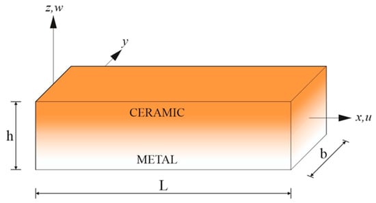
Figure 1.
Model geometry of a functionally graded beam.
For the numerical analysis, ABAQUS was employed. To ensure accurate and convergent results, the beams were modeled using second-order hexahedral elements (HEX20/C3D20). Each layer’s elastic modulus and density were defined according to the rule of mixtures, creating a smooth ceramic-to-metal material gradient along the beam. Natural frequencies were extracted using ABAQUS’s Eigensolver with the Lanczos algorithm for different slenderness ratios. To compare with the analytical solution, the numerical frequencies were also converted into dimensionless form.
While many studies have explored the mechanical behavior of FG beams using different deformation theories, to the best of the authors’ knowledge, no study has numerically modeled and solved FG beams in ABAQUS using both second-order hexahedral 3D solid elements (HEX20/C3D20) and 1D Timoshenko beam elements (B32). By examining both approaches on the same FG beam configurations, including variations in slenderness ratio and power–law index, we can directly compare the natural frequencies obtained from the 3D solid element model and the 1D Timoshenko beam model. Timoshenko B32 elements are particularly suitable for vibration analyses of short and thick beams because they account for both bending and shear deformations while keeping computational cost low. However, they offer lower accuracy compared to 3D solid elements like C3D20, and have limitations in modeling complex geometries and heterogeneous materials. This allows us to see which modeling approach converges most closely to the analytical solution. Such a comparison not only validates the numerical models, but also provides practical guidance on choosing the most suitable element type for capturing the dynamic behavior of FG beams. We believe that this study makes an important contribution to the literature, offering a clear reference for future investigations of FG beam vibrations and bridging the gap between detailed solid element modeling and efficient beam theory approaches.
2. Theory and Formulation
2.1. Material Properties
The variation in material properties is assumed to be governed by a power–law variation, defined as follows [5]:
Here, Pm and Pc denote the material properties, while Vm and Vc represent volume fractions of the metal and ceramic associated with the given subindices, respectively.
The volume fraction of the ceramic phase, described by a power–law distribution, is expressed as follows:
Here, h is the beam height and p is a positive parameter known as the power–law index, ranging 0 ≤ p ≤ ∞. When p = 0, the material is entirely ceramic. Using this relationship, the Young’s modulus and mass density are determined by the following expressions:
2.2. Constitutive Equations
The displacement field according to FSDT is expressed in a general form. It is important to note that, unlike the Euler–Bernoulli theory, the first-order shear component is also included in the field equations in this formulation [26],
where u and w show the axial and vertical displacement of the beam, and demonstrates the angle of rotation of the normal to the mid-surface of the beam.
The non-zero linear strains derived from Equations (5) and (6) are the following:
Assuming the material of the functionally graded (FG) beam obeys Hooke’s law, the stress components within the Timoshenko beam are expressed in matrix form as
where
2.3. Equations of Motion
The equations of motion are derived using Hamilton’s principle by integrating over time, as follows [27]:
Here, δU, δV, and δT represent the virtual variations of the strain energy, potential energy, and kinetic energy, respectively.
The variational form of the strain energy, δU, is given by:
Accordingly, the stress resultants Nx, Mx, and Qxz are defined as
where ks indicates shear coefficient.
The work done by the external vertical load q can be expressed as follows:
The kinetic energy δT can be written as follows [28]:
By substituting the variational expressions of δU, δV, and δT, presented in Equations (12), (14) and (15), respectively, into Equation (11), the governing equations of motion for the functionally graded beam are obtained as follows:
Here, the double dots above the parameters denote the components derived from the kinetic energy, representing the second derivatives with respect to time. The inertial coefficients are defined as follows:
By reformulating Equation (16) in conjunction with Equation (17), the governing equations of motion for the functionally graded material beam are comprehensively articulated and expressed as
where
3. Solution Procedure
3.1. Analytical Part of Solution
In this section, an analytical solution to the governing equations for the free vibration of a supported functionally graded beam is presented, based on the Navier method. The transverse load distribution is assumed to be zero. To this end, the displacement functions are expressed as the product of undetermined coefficients and known trigonometric functions, ensuring that the governing equations and boundary conditions are satisfied at x = 0 and x = L [28],
where the unknown Fourier coefficients Um, ξm, and Wm should be determined; w is the eigenfrequency associated with mth eigenmode, and .
For the simply supported beam, essential and natural boundary conditions are given as shown below [29]:
The following q load is considered as in study [27]:
By substituting the variables u0, ξ, and w0 from Equation (23) into the equations of motion, analytical solutions are obtained by evaluating the determinant of the matrix formed by the stiffness components Kij and mass components mij [28]. In the present study, qm is assumed to be zero (qm = 0).
where
3.2. Numerical Part
The commercial finite element package ABAQUS was employed to perform the numerical simulations. Pre-processing and post-processing tasks were conducted using ABAQUS/CAE (2023, Dassault Systèmes, Providence, RI, USA) [30], whereas the actual solution phase was carried out with the ABAQUS solver. To compute the natural frequencies of the models, a frequency extraction analysis was performed using the Lanczos eigensolver. The Lanczos method is widely recognized as a reliable approach for determining natural frequencies and is routinely applied in both modal analyses and frequency response function (FRF) evaluations. Finite element analysis (FEA) provides the ability to investigate structural responses for complex geometries, loading conditions, and material distributions. However, it is important to emphasize that FEA always produces approximate solutions. The accuracy of these solutions depends heavily on both mesh refinement and element type selection. In general, mesh convergence is improved by reducing element size and increasing the number of elements. Yet, excessively fine meshes lead to a significant increase in computational cost. Therefore, an optimal balance between accuracy and efficiency must be achieved. Moreover, the correct choice of element formulation is essential. In certain cases, first-order elements provide adequate accuracy, while in others, second-order elements are more appropriate. For solid models, hexahedral elements are usually preferred due to their numerical stability and convergence properties, while tetrahedral elements are adopted when handling irregular or complicated geometries. Similarly, the correct decision between solid, shell, and beam elements must be made depending on the geometry and structural characteristics under investigation. In the present study, two separate modeling strategies were adopted in ABAQUS to evaluate the natural frequencies of functionally graded beams. The first approach involved modeling the beams using 3D solid elements, while the second approach relied on 1D beam elements. For the solid element-based model, a second-order hexahedral mesh (HEX20/C3D20) was chosen to ensure analytical convergence and accuracy. Each element dimension was set to 5 × 5 × 5 mm, which provided a sufficient level of mesh quality. For the slender beam with a slenderness ratio of L/h = 20, the dimensions were 0.1 × 0.1 × 2 m, whereas for the short beam with L/h = 5, the dimensions were 0.1 × 0.1 × 0.5 m. To account for the material variation along the cross-section of the beam, the model was divided into 10 groups of elements. Each group was assigned its own material property set, allowing the smooth transition from metal to ceramic across the beam thickness to be accurately captured. Different power–law index (p) values were incorporated by defining separate material models for each case. To represent the simply supported boundary condition, rigid body elements were introduced at both ends of the beam. These rigid bodies were assigned appropriate constraints to their reference nodes, enabling one end to be fixed while allowing sliding at the other. Such an approach ensured the free rotation of the beam ends, consistent with the simply supported condition. The final solid-element-based finite element models contained approximately 160,000 hexahedral elements, two rigid body elements, and a total of 690,083 nodes for L/h = 20, and approximately 40,000 hexahedral elements, two rigid body elements, and 173,482 nodes for L/h = 5. In both cases, the ABAQUS solver was instructed to extract the first 10 natural frequencies.
A second modeling approach was carried out using 1D beam elements. Beam elements are generally advantageous when dealing with simple geometries, as they significantly reduce the number of degrees of freedom and computational effort. However, in the context of functionally graded materials (FGMs), additional care is required because the mechanical properties vary continuously within the material. This allows material transitions to be modeled accurately within individual elements, even in a 1D beam formulation. To achieve reliable and convergent results, the B32 Timoshenko beam element was selected. Timoshenko beam theory accounts for both bending and shear deformation, making it suitable for beams with lower slenderness ratios as well as for FGMs where shear flexibility cannot be neglected. A mesh size of 5 mm was employed to ensure the adequate quality and smooth distribution of material properties along the beam length. For L/h = 20, the dimensions were 0.1 × 0.1 × 2 m, discretized into 400 B32 elements, two rigid body elements, and 801 nodes, while for L/h = 5, the dimensions were 0.1 × 0.1 × 0.5 m, discretized into “100” B32 elements, two rigid body elements, and 201 nodes. As in the solid element case, the solver was requested to compute the first 10 natural frequencies. In summary, the study employed two complementary finite element approaches, a detailed 3D solid element model and a computationally efficient 1D beam element model to investigate the natural frequencies of functionally graded beams. While the 3D solid model captures the geometry and material distribution in greater detail, the beam element approach provides significant reductions in solution time while maintaining accuracy through the use of Timoshenko beam theory. The combination of these methods allows for both accuracy verification and computational efficiency, ensuring that the analysis of FGMs is both reliable and practical.
The modeling steps of the FGM beam in ABAQUS are presented as seen in Figure 2.
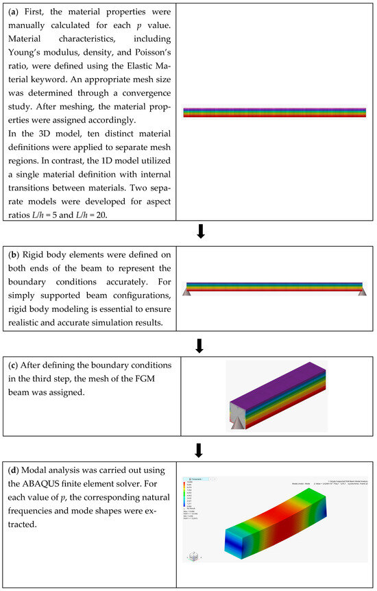
Figure 2.
Flowchart for the modeling of the FGM beam.
4. Results and Discussion
The free vibration behavior of the first mode of FG Timoshenko beams was analyzed for two different length-to-height ratios, using the material properties listed in Table 1 as a reference.

Table 1.
Material properties of the FGM beam [27,31].
For different power–law index values, the results obtained from analytical and numerical solutions are presented in Table 2, Table 3 and Table 4, plotted as seen Figure 3 and Figure 4 and compared with those reported in the literature.
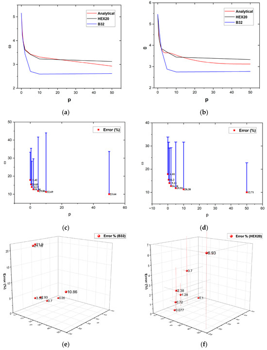
Figure 3.
(a) Comparison of dimensionless frequencies values obtained from analytical and numerical solutions for the L/h = 5 (m = 1). (b) Comparison of dimensionless frequencies values obtained from analytical and numerical solutions for the L/h = 20 (m = 1). (c) Percentage error of the dimensionless frequency obtained from the numerical results (B32) compared to the analytical reference results (L/h = 5, m = 2). (d) Percentage error of the dimensionless frequency obtained from the numerical results (HEX20) compared to the analytical reference results (L/h = 5, m = 2). (e) Three-dimensional percentage error of the dimensionless frequency obtained from the numerical results (B32) compared to the analytical reference results (L/h = 20, m = 3). (f) Three-dimensional percentage error of the dimensionless frequency obtained from the numerical results (HEX20) compared to the analytical reference results (L/h = 20, m = 3).
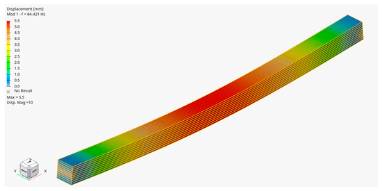
Figure 4.
ABAQUS model of FG beam (HEX20).
The dimensionless frequency can be calculated using the following formula [32]:

Table 2.
Comparison of dimensionless natural frequencies of simply supported FG beams for the first mode.
Table 2.
Comparison of dimensionless natural frequencies of simply supported FG beams for the first mode.
| L/h | p | Present (TBT) | ABAQUS (HEX20) | ABAQUS (Timoshenko 1D) | Chen et al. [33] | CBT [31] |
|---|---|---|---|---|---|---|
| 0 | 5.1524 | 5.1563 | 5.1569 | 5.1525 | 5.3953 | |
| 0.5 | 4.4078 | 4.2450 | 4.2354 | 4.4079 | 4.5931 | |
| 1 | 3.9902 | 3.9370 | 3.9623 | 3.9904 | 4.1484 | |
| 5 | 2 | 3.6343 | 3.6021 | 3.4407 | 3.6346 | 3.7793 |
| 5 | 3.4312 | 3.4200 | 2.7061 | 3.4315 | 3.5949 | |
| 10 | 3.3134 | 3.2315 | 2.5960 | 3.3136 | 3.4921 | |
| 50 | 2.9288 | 3.1269 | 2.6182 | - | - | |
| 0 | 5.4603 | 5.4612 | 5.4607 | 5.4603 | 5.4777 | |
| 0.5 | 4.6509 | 4.4791 | 5.0114 | 4.6509 | 4.6641 | |
| 1 | 4.2050 | 4.1685 | 4.5509 | 4.2051 | 4.2163 | |
| 20 | 2 | 3.8367 | 3.8463 | 3.8015 | 3.8368 | 3.8472 |
| 5 | 3.6508 | 3.6858 | 2.8814 | 3.6509 | 3.6628 | |
| 10 | 3.5415 | 3.4493 | 2.7494 | 3.5416 | 3.5547 | |
| 50 | 3.1207 | 3.3338 | 2.7724 | - | - |

Table 3.
Comparison of dimensionless natural frequencies of simply supported FG beams for the second mode.
Table 3.
Comparison of dimensionless natural frequencies of simply supported FG beams for the second mode.
| L/h | p | Present (TBT) | ABAQUS (HEX20) | ABAQUS (Timoshenko 1D) | Chen et al. [33] | CBT [27] |
|---|---|---|---|---|---|---|
| 0 | 17.8711 | 15.0112 | 15.1155 | 17.8711 | 20.6187 | |
| 0.5 | 15.4263 | 12.9269 | 12.3368 | 15.4277 | 17.5415 | |
| 1 | 14.0030 | 11.8785 | 11.9982 | 14.0064 | 15.7982 | |
| 5 | 2 | 12.7120 | 10.6079 | 10.5592 | 12.7179 | 14.3260 |
| 5 | 11.8157 | 9.4636 | 8.2881 | 11.8226 | 13.5876 | |
| 10 | 11.3073 | 9.0001 | 7.6107 | 11.3119 | 13.2376 | |
| 50 | 10.0500 | 8.7717 | 7.6743 | - | - | |
| 0 | 21.5732 | 21.5831 | 21.5782 | 21.5732 | 21.8438 | |
| 0.5 | 18.3931 | 17.7203 | 19.2787 | 18.3931 | 18.5987 | |
| 1 | 16.6344 | 16.4784 | 17.6408 | 16.6344 | 16.8100 | |
| 20 | 2 | 15.1715 | 15.1744 | 14.8756 | 15.1715 | 15.3334 |
| 5 | 14.4109 | 14.5201 | 11.3722 | 14.4110 | 14.5959 | |
| 10 | 13.9652 | 13.6022 | 10.8641 | 13.9653 | 14.1676 | |
| 50 | 12.3146 | 13.1533 | 10.9555 | - | - |

Table 4.
Comparison of dimensionless natural frequencies of simply supported FG beams for the third mode.
Table 4.
Comparison of dimensionless natural frequencies of simply supported FG beams for the third mode.
| L/h | p | Present (TBT) | ABAQUS (HEX20) | ABAQUS (Timoshenko 1D) | Chen et al. [33] | CBT [27] |
|---|---|---|---|---|---|---|
| 0 | 34.1449 | 34.2776 | 34.2807 | 34.1449 | 43.3483 | |
| 0.5 | 29.7166 | 28.9559 | 20.8563 | 29.7231 | 36.8308 | |
| 1 | 27.0525 | 26.8252 | 20.7280 | 27.0683 | 33.0278 | |
| 5 | 2 | 24.4970 | 23.9218 | 19.8466 | 24.5242 | 29.7458 |
| 5 | 22.4642 | 20.9403 | 17.6138 | 22.4933 | 28.0850 | |
| 10 | 21.3219 | 20.9403 | 17.2456 | 21.3399 | 27.4752 | |
| 50 | 19.0238 | 19.3222 | 17.4048 | - | - | |
| 0 | 47.5921 | 47.6399 | 47.6167 | 47.5921 | 48.8999 | |
| 0.5 | 40.6377 | 39.1212 | 40.9196 | 40.6378 | 41.6328 | |
| 1 | 36.7673 | 36.2973 | 37.8398 | 36.7677 | 37.6173 | |
| 20 | 2 | 33.5135 | 33.2699 | 32.3465 | 33.5142 | 34.2954 |
| 5 | 31.7473 | 31.7229 | 25.0470 | 31.7482 | 32.6357 | |
| 10 | 30.7174 | 29.9764 | 23.9720 | 30.7180 | 31.6883 | |
| 50 | 27.1162 | 28.9962 | 24.1755 | - | - |
5. Conclusions
In this study, the free vibration behavior of functionally graded (FG) beams was investigated using both analytical formulations and numerical simulations (ABAQUS solver). The analysis was carried out within the framework of Timoshenko beam theory, also known as the first-order shear deformation theory (FSDT). The primary objective was to demonstrate that, although FG structures are often challenging to analyze analytically, finite element software can provide an effective and reliable tool for addressing such problems. To this end, the governing equations were derived by incorporating shear effects and applying the principle of minimum potential energy, and the resulting dimensionless natural frequencies were obtained and compared with those from numerical models.
Two different modeling strategies were carried out in ABAQUS alongside the analytical approach. A HEX20 solid element model was built where the material gradation was defined layer by layer, while a B32 Timoshenko beam element was used to develop a beam-type 1D model. The free vibration frequencies were calculated for the first three modes under simply supported boundary conditions, considering two slenderness ratios (L/h = 5 and L/h = 20) and a range of power–law index (p) values. Results were also obtained for p = 50, which have not been reported in the literature so far. To the best of our knowledge, no other study has modeled both solid and 1D elements in ABAQUS and compared them systematically with each other, as well as with the analytical solution, which highlights the originality of this work.
As can be seen from Table 2, Table 3 and Table 4 and Figure 3, the results for all three modes indicate that the HEX20 solid element model shows consistent agreement with the analytical solutions. In contrast, the frequencies obtained from the B32 Timoshenko beam element exhibit slightly larger deviations from the analytical results compared to the HEX20 model, especially beyond a certain p value. This behavior is thought to stem from how the 1D element represents gradation transition, which introduces irregularities in the results. In addition, Figure 5, Figure 6, Figure 7, Figure 8, Figure 9 and Figure 10 present the frequencies obtained for both the HEX20 solid element and the B32 beam element, corresponding to the first three modes at a selected value of p. Overall, the authors believe that the outcomes of this study can serve as a practical reference for the computational analysis of FGM structures, and offer guidance for future research in the field.
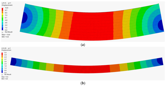
Figure 5.
The first mode of the FG beam (a) for the length-to-height ratio (L/h = 5) and p = 1, and (b) for (L/h = 20) and p = 1 (HEX20).
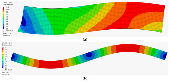
Figure 6.
The second mode of the FG beam (a) for the length-to-height ratio (L/h = 5) and p = 1, and (b) for (L/h = 20) and p = 1 (HEX20).
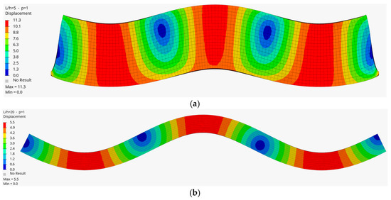
Figure 7.
The third mode of the FG beam (a) for the length-to-height ratio (L/h = 5) and p = 1, and (b) for (L/h = 20) and p = 1 (HEX20).
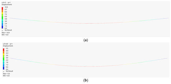
Figure 8.
The first mode of the FG beam (a) for the length-to-height ratio (L/h = 5) and p = 1, and (b) for (L/h = 20) and p = 1 (Timoshenko beam).
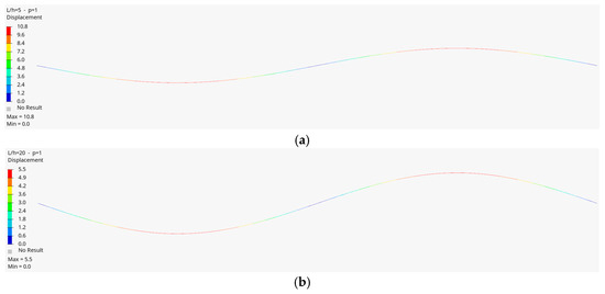
Figure 9.
The second mode of the FG beam (a) for the length-to-height ratio (L/h = 5) and p = 1, and (b) for (L/h = 20) and p = 1 (Timoshenko beam).
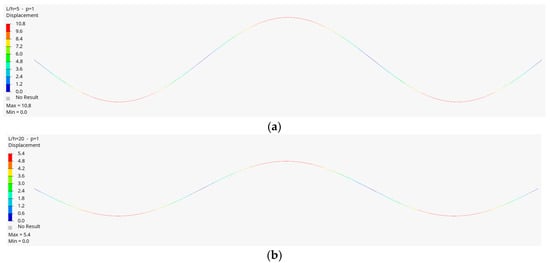
Figure 10.
The third mode of the FG beam (a) for the length-to-height ratio (L/h = 5) and p = 1, and (b) for (L/h = 20) and p = 1 (Timoshenko beam).
Author Contributions
Methodology, M.Ç.; Software, A.F.Y.; Validation, A.F.Y.; Formal analysis, M.Ç.; Investigation, M.Ç. and E.D.; Resources, A.F.Y.; Writing—original draft, E.D.; Writing—review and editing, M.Ç.; Supervision, M.Ç. All authors have read and agreed to the published version of the manuscript.
Funding
This research received no external funding.
Institutional Review Board Statement
Not applicable.
Informed Consent Statement
Not applicable.
Data Availability Statement
The data presented in this study are available on request from the corresponding author.
Conflicts of Interest
The authors declare no conflicts of interest.
References
- Qian, L.F.; Batra, R.C.; Chen, L.M. Static and dynamic deformations of thick functionally graded elastic plates by using higher-order shear and normal deformable plate theory and meshless local Petrov–Galerkin method. Compos. Part B Eng. 2004, 35, 685–697. [Google Scholar] [CrossRef]
- Reddy, J. Thermomechanical Behavior of Functionally Graded Materials, 1st ed.; Department of Mechanical Engineering, Texas A&M University: College Station, TX, USA, 1998; pp. 3–20. [Google Scholar]
- Rahmani, A.; Babaei, A.; Faroughi, S. Vibration Characteristics of Functionally Graded Micro-Beam Carrying an Attached Mass. Mech. Pf Adv. Compos. Struct. 2020, 7, 49–58. [Google Scholar]
- Sedighi, H.M.; Keivani, M.; Abadyan, M. Modified continuum model for stability analysis of asymmetric FGM double-sided NEMS: Corrections due to finite conductivity, surface energy and nonlocal effect. Compos. Part B Eng. 2015, 83, 117–133. [Google Scholar] [CrossRef]
- Alshorbagy, A.E.; Eltaher, M.A.; Mahmoud, F.F. Free vibration characteristics of a functionally graded beam by finite element method. Appl. Math. Model. 2011, 35, 412–425. [Google Scholar] [CrossRef]
- Avcar, M. Free vibration of imperfect sigmoid and power law functionally graded beams. Steel Compos. Struct. 2019, 30, 603–615. [Google Scholar]
- Kahya, V.; Turan, M. Finite element model for vibration and buckling of functionally graded beams based on the first-order shear deformation theory. Compos. Part B Eng. 2017, 109, 108–115. [Google Scholar] [CrossRef]
- Çelik, M.; Artan, R. An investigation of static bending of a bi-directional strain-gradient Euler–Bernoulli nano-beams with the method of initial values. Microsyst. Technol. 2020, 26, 2921–2929. [Google Scholar] [CrossRef]
- Kareem, M.G.; Sadiq, S.E.; Al-Raheem, S.K.; Alansari, L.S. Analysis the free vibration of functionally graded material plate by using new displacement function. Results Eng. 2025, 25, 103756. [Google Scholar] [CrossRef]
- Su, X.S.; Hu, T.; Zhang, W.; Kang, H.; Cong, Y.; Yuan, Q. Transfer matrix method for free and forced vibrations of multi-level functionally graded material stepped beams with different boundary conditions. Appl. Math. Mech. 2024, 45, 983–1000. [Google Scholar] [CrossRef]
- El Hantati, I.; Ouyassafte, O.; El Khouddar, Y.; Belhaou, M.; Adri, A.; Benamar, R. Analysis of the transverse vibration of a multistepped FGM beam resting on a Winkler foundation in a thermal environment and carrying concentrated masses. Results Eng. 2024, 23, 102822. [Google Scholar] [CrossRef]
- Wang, Y.; Liu, B.; Zhu, J.; Zhou, W.; Jiang, L.; Pan, C.; Xu, J. Thermal vibration of stiffened FGM plates with cutouts using Nitsche-based isogeometric approach. Thin-Walled Struct. 2025, 210, 113026. [Google Scholar] [CrossRef]
- Hilali, Y.; Rassam, M.; Mesmoudi, S.; Sitli, Y.; Elmhaia, O.; Rammane, M.; Askour, O.; Bourihane, O. A high-order approach for thermal buckling and post-buckling analysis of functionally graded sandwich beams. Acta Mech. 2025, 236, 3543–3563. [Google Scholar] [CrossRef]
- Pradhan, K.K.; Chakraverty, S. Free vibration of Euler and Timoshenko functionally graded beams by Rayleigh–Ritz method. Compos. Part B Eng. 2013, 51, 175–184. [Google Scholar] [CrossRef]
- Yıldırım, B. Investigation of thermal shock fracture in an edge-cracked functionally graded layer using finite element method. J. Fac. Eng. Archit. Gazi Univ. 2004, 19, 235–245. [Google Scholar]
- Kahya, V.; Turan, M. Vibration and stability analysis of functionally graded sandwich beams by a multi-layer finite element. Compos. Part B Eng. 2018, 146, 198–212. [Google Scholar] [CrossRef]
- Nguyen, T.K.; Nguyen, B.D. A new higher-order shear deformation theory for static, buckling and free vibration analysis of functionally graded sandwich beams. J. Sandw. Struct. Mater. 2015, 17, 613–631. [Google Scholar] [CrossRef]
- Echouai, B.; Adri, A.; El Khouddar, Y.; Outassafte, O.; El Hantati, I.; Echouai, E.K.; Hassa, M.; Benamar, R. Analysis of transverse vibrations of functionally graded beams with magnetostrictive Terfenol-D layers resting on an elastic foundation. Sci. Afr. 2025, 28, e02651. [Google Scholar] [CrossRef]
- Benadouda, M.; Bourouis, M.E.A.; Dahmane, M.; Bennai, R.; Atmane, H.A.; Safer, O. Dynamic response of wave propagation in functionally graded beams with defects: Effects of porosity and cracks. Acta Mech. 2025, 236, 2279–2296. [Google Scholar] [CrossRef]
- Jayachandiran, G.; Ramamoorthy, M. Free and forced vibration analysis of functionally graded composite beam with graphene filler reinforcement—Experimental and simulation study. Polym. Compos. 2025, 46, S70–S85. [Google Scholar] [CrossRef]
- Priyadarshini, A.; Sutar, M.K.; Pattnaik, S. Refined Higher-Order Shear Deformation Analysis of Axial Functionally Graded Beams With Nano-Graphene Reinforcement. J. Vib. Eng. Technol. 2025, 13, 236. [Google Scholar] [CrossRef]
- Hedia, H.S.; Almas, M.A.; Attar, H.M.; Hedia, M.H.; Gadelmawla, E.S.; Soliman, M.A. Numerical and analytical stress analysis for a FGM beam. Mater. Test. 2025, 67, 1046–1055. [Google Scholar] [CrossRef]
- Abood, N.K.; Al-Ansari, L.S. Impact of porosity distribution on vibration of porous functionally graded beams. Math. Model. Eng. Probl. 2025, 12, 687–708. [Google Scholar] [CrossRef]
- Özmen, U.; Özhan, B.B. Mechanics of functionally graded beams: Analytical, computational, and experimental analyses. Int. J. Mech. Mater. Des. 2025, 21, 577–590. [Google Scholar] [CrossRef]
- Khan, A.A.; Alam, M.N.; ur Rahman, N.; Wajid, M. Finite element modelling for static and free vibration response of functionally graded beam. Lat. Am. J. Solids Struct. 2016, 13, 690–714. [Google Scholar] [CrossRef]
- Chakraborty, A.; Gopalakrishnan, S.; Reddy, J.N. A new beam finite element for the analysis of functionally graded materials. Int. J. Mech. Sci. 2003, 45, 519–539. [Google Scholar] [CrossRef]
- Thai, H.T.; Vo, T.P. Bending and free vibration of functionally graded beams using various higher-order shear deformation beam theories. Int. J. Mech. Sci. 2012, 62, 57–66. [Google Scholar] [CrossRef]
- Larbi, O.L.; Kaci, A.; Houari, M.S.A.; Tounsi, A. An Efficient Shear Deformation Beam Theory Based on Neutral Surface Position for Bending and Free Vibration of Functionally Graded Beams. Mech. Based Des. Struct. Mach. 2013, 41, 421–433. [Google Scholar] [CrossRef]
- Aydogdu, M.; Taskin, V. Free vibration analysis of functionally graded beams with simply supported edges. Mater. Des. 2007, 28, 1651–1656. [Google Scholar] [CrossRef]
- Dassault Systemes, “ABAQUS FEA”. 2024. Available online: https://www.3ds.com/products/simulia/abaqus (accessed on 20 August 2025).
- Çelik, M.; Gündoğdu, E.; Özdilek, E.E.; Demirkan, E.; Artan, R. Artificial Neural Net-work (ANN) Validation Research: Free Vibration Analysis of Functionally Graded Beam via Higher-Order Shear Deformation Theory and Artificial Neural Network Method. Appl. Sci. 2024, 14, 217. [Google Scholar] [CrossRef]
- Zohra, Z.; Lemya, H.; Abderahman, Y.; Mustapha, M.; Abdelouahed, T.; Djamel, O. Free vibration analysis of functionally graded beams using a higher-order shear deformation theory. Math. Model. Eng. Probl. 2017, 4, 7–12. [Google Scholar] [CrossRef]
- Chen, W.R.; Chang, H. Vibration Analysis of Functionally Graded Timoshenko Beams. Int. J. Struct. Stab. Dyn. 2018, 18, 185007. [Google Scholar] [CrossRef]
Disclaimer/Publisher’s Note: The statements, opinions and data contained in all publications are solely those of the individual author(s) and contributor(s) and not of MDPI and/or the editor(s). MDPI and/or the editor(s) disclaim responsibility for any injury to people or property resulting from any ideas, methods, instructions or products referred to in the content. |
© 2025 by the authors. Licensee MDPI, Basel, Switzerland. This article is an open access article distributed under the terms and conditions of the Creative Commons Attribution (CC BY) license (https://creativecommons.org/licenses/by/4.0/).