
Formation of Intermetallic Coatings on Titanium by Explosive Welding and Subsequent Heat Treatment of the Layered Metal Composite

 ,
,  , and
, and
Abstract
1. Introduction
2. Materials and Methods
3. Results and Discussion
4. Conclusions
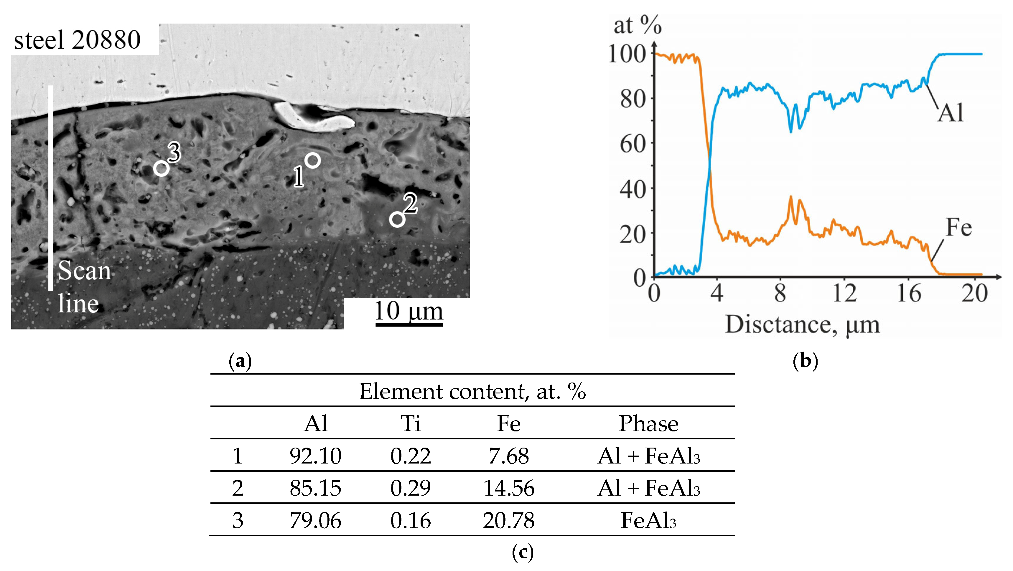
- Explosive welding using a plane-parallel scheme at optimal process parameters ensures the fabrication of a three-layer titanium VT1-0—aluminum AD1—steel 20880 composite with a minimum level of chemical microheterogeneity (molten metal) at its interlayer boundaries. At the VT1-0—AD1 interlayer boundary the molten metal crystallized in the form of a continuous layer, consisting of a mechanical mixture of Al + TiAl3, and at the AD1- steel 20880 boundary—mainly in the form of separate small areas, consisting of a mechanical mixture of Al + FeAl3. The microhardness of the molten metal is within 1.5–3 GPa.
- Heat treatment of explosively welded three-layer composite at 640 °C for 1 h leads to the formation of the brittle Fe2Al5 intermetallic layer in the diffusion zone at the aluminum-steel interface. Upon cooling, a main crack forms in this layer, leading to spontaneous separation of the protective steel layer from the aluminum.
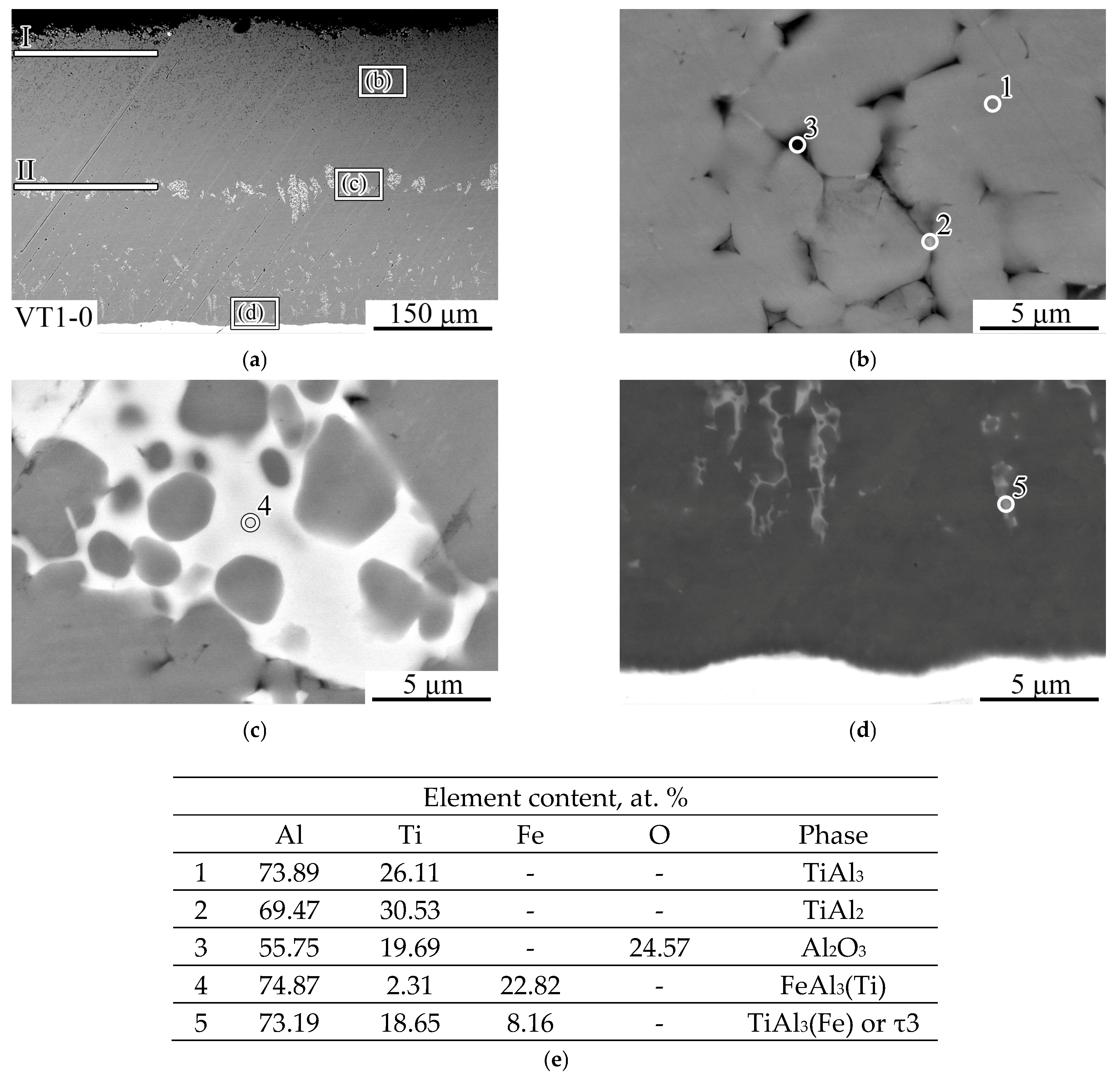
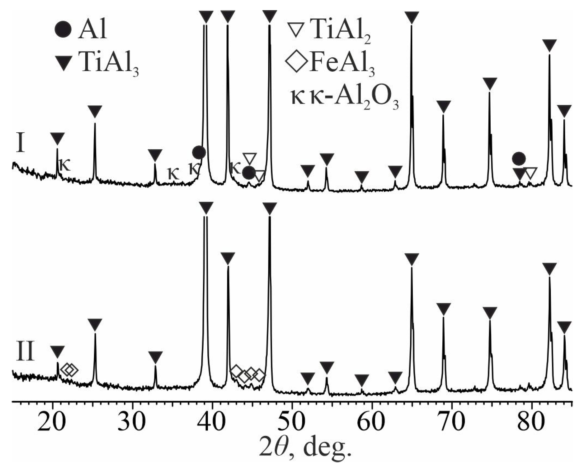
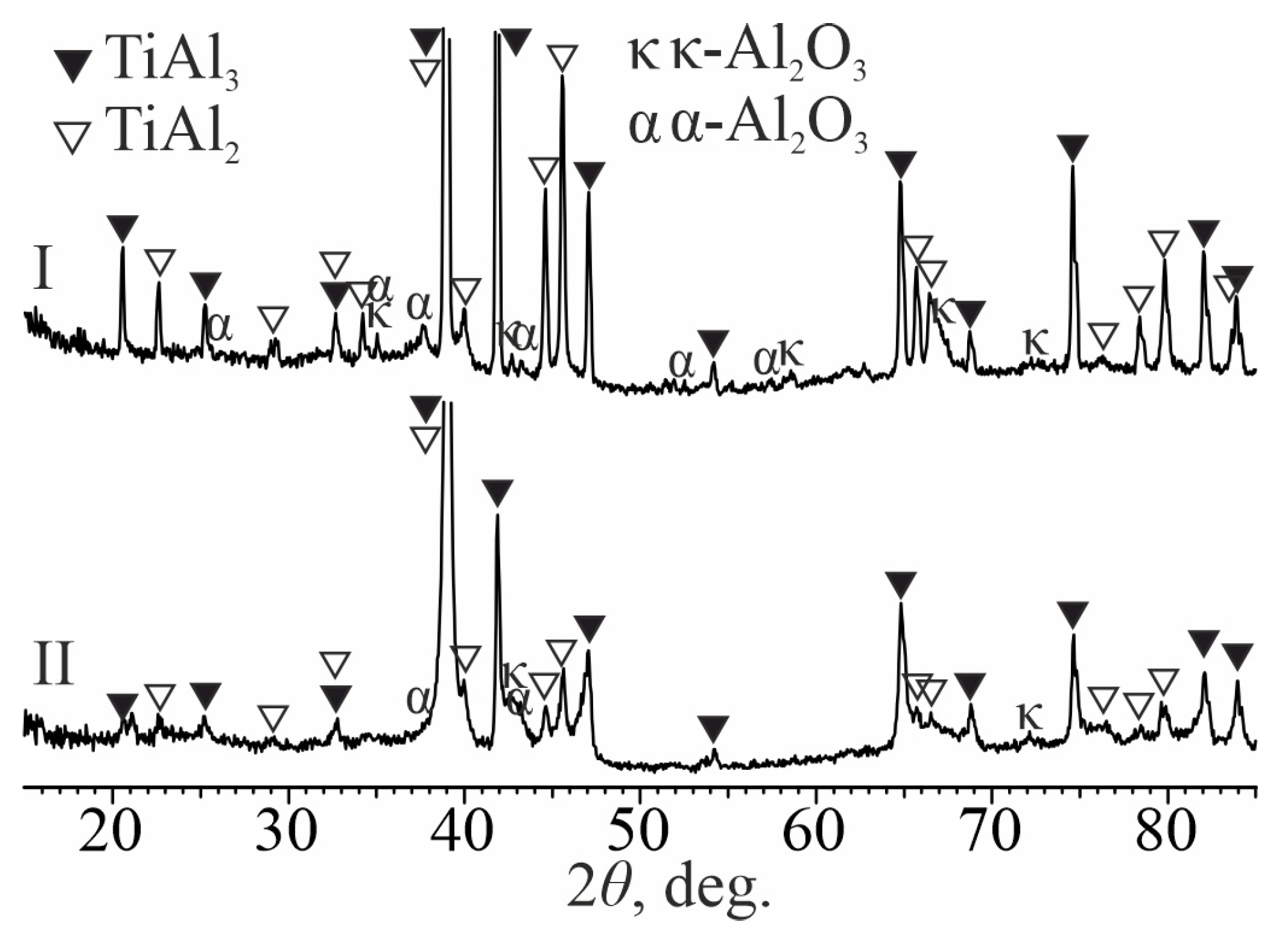
- Heat treatment of aluminum-coated titanium at temperatures of 700 and 850 °C leads to the formation of a diffusion layer on its surface based on TiAl3 titanium aluminide, which fills the entire volume of molten aluminum, due to a gradual increase in its thickness. The layer grows due to the upward transportation of TiAl3 fragments, which are separated from the diffusion zone by circulating melt flows. At the same time, a frame-type structure of the coating is formed, in which TiAl3 intermetallic particles are separated from each other by an oxide phase containing ~25 at. % oxygen. Between the coating and the titanium substrate there is a diffusion layer ~5–10 μm thick, consisting of continuous layers of TiAl2, TiAl, and Ti3Al (as they approach titanium). The mechanism of its formation is driven by solid-phase reactions occurring along the concentration gradient at the coating–titanium interface in the following sequence: TiAl3→TiAl2→TiAl→Ti3Al.
- The microhardness of the coating with the TiAl3 + Al2O3 frame-type structure decreases with increasing heat treatment temperature from ~5.0–5.5 GPa to 3.3 GPa due to the increasing separation of individual TiAl3 intermetallic particles by an oxide phase. As the interface with titanium is approached, the microhardness increases to 6.0 GPa, which corresponds to the hardness of solid TiAl3.
Author Contributions
Funding
Data Availability Statement
Acknowledgments
Conflicts of Interest
References
- Gialanella, S.; Malandruccolo, A. Titanium and Titanium Alloys. In Aerospace Alloys; Topics in Mining, Metallurgy and Materials Engineering; Springer International Publishing: Cham, Switzerland, 2020; pp. 129–189. ISBN 978-3-030-24439-2. [Google Scholar]
- Dai, J.; Zhu, J.; Chen, C.; Weng, F. High Temperature Oxidation Behavior and Research Status of Modifications on Improving High Temperature Oxidation Resistance of Titanium Alloys and Titanium Aluminides: A Review. J. Alloys Compd. 2016, 685, 784–798. [Google Scholar] [CrossRef]
- Dong, E.; Yu, W.; Cai, Q.; Cheng, L.; Shi, J. High-Temperature Oxidation Kinetics and Behavior of Ti–6Al–4V Alloy. Oxid. Met. 2017, 88, 719–732. [Google Scholar] [CrossRef]
- Valenza, T.C.; Weber, P.K.; Marquis, E.A. Role of Nitrogen in the High-Temperature Oxidation of Titanium Alloys. Corros. Sci. 2024, 235, 112164. [Google Scholar] [CrossRef]
- Gurrappa, I.; Gogia, A.K. Development of Oxidation Resistant Coatings for Titanium Alloys. Mater. Sci. Technol. 2001, 17, 581–587. [Google Scholar] [CrossRef]
- Froes, F.H.; Suryanarayana, C.; Eliezer, D. Synthesis, Properties and Applications of Titanium Aluminides. J. Mater. Sci. 1992, 27, 5113–5140. [Google Scholar] [CrossRef]
- Zarchi, H.R.K.; Soltanieh, M.; Aboutalebi, M.R.; Guo, X. Thermodynamic Study on Pack Aluminizing Systems of Pure Titanium and Nickel. Trans. Nonferrous Met. Soc. China 2013, 23, 1838–1846. [Google Scholar] [CrossRef]
- Szkliniarz, W.; Moskal, G.; Szkliniarz, A.; Swadźba, R. The Influence of Aluminizing Process on the Surface Condition and Oxidation Resistance of Ti–45Al–8Nb–0.5(B, C) Alloy. Coatings 2018, 8, 113. [Google Scholar] [CrossRef]
- Du, H.; Tan, N.; Fan, L.; Zhuang, J.; Qiu, Z.; Lei, Y. Formation Mechanism of Aluminide Diffusion Coatings on Ti and Ti-6Al-4V Alloy at the Early Stages of Deposition by Pack Cementation. Materials 2019, 12, 3097. [Google Scholar] [CrossRef]
- Yumoto, A.; Hiroki, F.; Shiota, I.; Niwa, N. In Situ Synthesis of Titanium-Aluminides in Coating with Supersonic Free-Jet PVD Using Ti and Al Nanoparticles. Surf. Coat. Technol. 2003, 169–170, 499–503. [Google Scholar] [CrossRef]
- Pyachin, S.A.; Burkov, A.A.; Komarova, V.S. Formation and Study of Electrospark Coatings Based on Titanium Aluminides. J. Synch. Investig. 2013, 7, 515–522. [Google Scholar] [CrossRef]
- Baptista, A.; Silva, F.; Porteiro, J.; Míguez, J.; Pinto, G. Sputtering Physical Vapour Deposition (PVD) Coatings: A Critical Review on Process Improvement and Market Trend Demands. Coatings 2018, 8, 402. [Google Scholar] [CrossRef]
- Mridha, S.; Baker, T.N. Oxidation Protection Behaviour of Titanium Aluminide Coatings Developed by TIG Technique. Adv. Mater. Process. Technol. 2015, 1, 453–464. [Google Scholar] [CrossRef]
- Mizuta, N.; Matsuura, K.; Kirihara, S.; Miyamoto, Y. Titanium Aluminide Coating on Titanium Surface Using Three-Dimensional Microwelder. Mater. Sci. Eng. A 2008, 492, 199–204. [Google Scholar] [CrossRef]
- Henckell, P.; Ali, Y.; Metz, A.; Bergmann, J.P.; Reimann, J. In Situ Production of Titanium Aluminides during Wire Arc Additive Manufacturing with Hot-Wire Assisted GMAW Process. Metals 2019, 9, 578. [Google Scholar] [CrossRef]
- Hoosain, S.E.; Pityana, S.; Freemantle, C.S.; Tlotleng, M. Heat Treatment of In Situ Laser-Fabricated Titanium Aluminide. Metals 2018, 8, 655. [Google Scholar] [CrossRef]
- Maliutina, I.N.; Si-Mohand, H.; Sijobert, J.; Bertrand, P.; Lazurenko, D.V.; Bataev, I.A. Structure and Oxidation Behavior of γ-TiAl Coating Produced by Laser Cladding on Titanium Alloy. Surf. Coat. Technol. 2017, 319, 136–144. [Google Scholar] [CrossRef]
- Lazurenko, D.V.; Golkovsky, M.G.; Stark, A.; Pyczak, F.; Bataev, I.A.; Ruktuev, A.A.; Petrov, I.Y.; Laptev, I.S. Structure and Properties of Ti-Al-Ta and Ti-Al-Cr Cladding Layers Fabricated on Titanium. Metals 2021, 11, 1139. [Google Scholar] [CrossRef]
- Cizek, J.; Man, O.; Roupcova, P.; Loke, K.; Dlouhy, I. Oxidation Performance of Cold Spray Ti–Al Barrier Coated γ-TiAl Intermetallic Substrates. Surf. Coat. Technol. 2015, 268, 85–89. [Google Scholar] [CrossRef]
- Balcı, E.; Karakaş, A.; Bayram, B.; Kaba, M.; Muhaffel, F.; Tilki, P.K.; Tan, E.; Baydoğan, M. Formation of In Situ Al/TiAl3 Coatings on Electron Beam Melted (EBM) Ti-6Al-4V Alloy by Cold Spray and Induction Heating. J. Therm. Spray. Tech. 2025, 34, 1685–1699. [Google Scholar] [CrossRef]
- Ulianitsky, V.Y.; Dudina, D.V.; Shtertser, A.A.; Smurov, I. Computer-Controlled Detonation Spraying: Flexible Control of the Coating Chemistry and Microstructure. Metals 2019, 9, 1244. [Google Scholar] [CrossRef]
- Sienkiewicz, J.; Kuroda, S.; Murakami, H.; Araki, H.; Giżyński, M.; Kurzydłowski, K.J. Fabrication and Oxidation Resistance of TiAl Matrix Coatings Reinforced with Silicide Precipitates Produced by Heat Treatment of Warm Sprayed Coatings. J. Therm. Spray. Tech. 2018, 27, 1165–1176. [Google Scholar] [CrossRef]
- Sasaki, T.; Yagi, T.; Watanabe, T.; Yanagisawa, A. Aluminizing of TiAl-Based Alloy Using Thermal Spray Coating. Surf. Coat. Technol. 2011, 205, 3900–3904. [Google Scholar] [CrossRef]
- Bogdanov, A.I.; Kulevich, V.P.; Shmorgun, V.G.; Gurevich, L.M. Structure and Properties of Ti-Al Intermetallic Coatings Reinforced with an Aluminum Oxide Filler. Metals 2024, 14, 1336. [Google Scholar] [CrossRef]
- Deqing, W.; Ziyuan, S.; Yingli, T. Microstructure and Oxidation of Hot-Dip Aluminized Titanium at High Temperature. Appl. Surf. Sci. 2005, 250, 238–246. [Google Scholar] [CrossRef]
- Patel, P.; Jamnapara, N.I.; Zala, A.; Kahar, S.D. Investigation of Hot-Dip Aluminized Ti6Al4V Alloy Processed by Different Thermal Treatments in an Oxidizing Atmosphere. Surf. Coat. Technol. 2020, 385, 125323. [Google Scholar] [CrossRef]
- Patel, P.; Zala, A.; Parekh, T.; Kahar, S.D.; Jamnapara, N.I. High Temperature Oxidation Behavior of Thermal and Plasma Processed Aluminide Coated Ti6Al4V Alloys. Surf. Coat. Technol. 2022, 447, 128839. [Google Scholar] [CrossRef]
- Wang, X.; Li, C.; Li, M.; Cao, J. Enhancing High-Temperature Oxidation Resistance of Ti6Al4V Alloy by Simple Surface Aluminization. Corros. Sci. 2021, 192, 109810. [Google Scholar] [CrossRef]
- Zhang, Z.G.; Peng, Y.P.; Mao, Y.L.; Pang, C.J.; Lu, L.Y. Effect of Hot-Dip Aluminizing on the Oxidation Resistance of Ti–6Al–4V Alloy at High Temperatures. Corros. Sci. 2012, 55, 187–193. [Google Scholar] [CrossRef]
- Findik, F. Recent Developments in Explosive Welding. Mater. Des. 2011, 32, 1081–1093. [Google Scholar] [CrossRef]
- Shmorgun, V.; Bogdanov, A.; Kulevich, V.; Taube, A. Experimental Research of the Explosive Welding of Metal Plates with Different Initial Hardness. Mater. Manuf. Process. 2024, 39, 207–216. [Google Scholar] [CrossRef]
- Zhang, T.; Wang, W.; Yan, Z.; Zhang, J. Interfacial Morphology and Bonding Mechanism of Explosive Weld Joints. Chin. J. Mech. Eng. 2021, 34, 8. [Google Scholar] [CrossRef]
- Gurevich, L.M.; Shmorgun, V.G. Intermetallic Compound Formation During Reaction of Molten Aluminum with Titanium. Metallurgist 2016, 59, 1221–1227. [Google Scholar] [CrossRef]
- Shmorgun, V.G.; Bogdanov, A.I.; Kulevich, V.P. Structure and Phase Composition of the Al-Ti System Composites after Heat Treatment. Defect Diffus. Forum 2021, 410, 519–524. [Google Scholar] [CrossRef]
- Shmorgun, V.G.; Slautin, O.V.; Kulevich, V.P. Features of Diffusion Interaction in Steel-Aluminum Composite After Explosive Welding and Aluminizing by Melt Immersion. Metallurgist 2019, 63, 766–774. [Google Scholar] [CrossRef]
- Bogdanov, A.; Kulevich, V.; Shmorgun, V.; Taube, A. Formation of Thermally Grown Aluminum Oxide Scale on the Surface of Ni2Al3/Ni Layered Coating. Oxid. Met. 2022, 98, 199–216. [Google Scholar] [CrossRef]
- Shmorgun, V.G.; Bogdanov, A.I.; Taube, A.O.; Kulevich, V.P. Evaluation of Heat Resistance and Thermal Conductivity of Ni–Cr–Al System Layered Coatings. Metallurgist 2022, 66, 934–941. [Google Scholar] [CrossRef]
- Shmorgun, V.G.; Bogdanov, A.I.; Kulevich, V.P. The Effect of Aluminum Content in the Fe-Cr-Al System Alloys on the Oxide Films Phase Composition. Mater. Today: Proc. 2020, 30, 554–558. [Google Scholar] [CrossRef]
- Murray, J.L. (Ed.) Phase Diagrams of Binary Titanium Alloys; Monograph series on alloy phase diagrams; 2. print. ASM International: Metals Park, OH, USA, 1990; ISBN 978-0-87170-248-7. [Google Scholar]
- Rehbinder, P.A.; Shchukin, E.D. Surface Phenomena in Solids during Deformation and Fracture Processes. Prog. Surf. Sci. 1972, 3, 97–188. [Google Scholar] [CrossRef]
- Schuster, J.C.; Palm, M. Reassessment of the Binary Aluminum-Titanium Phase Diagram. J. Phase Equilibria Diffus. 2006, 27, 255–277. [Google Scholar] [CrossRef]


| Ti | Fe | Si | N | O | H | C | Others |
|---|---|---|---|---|---|---|---|
| 99.24–99.70 | ≤0.25 | ≤0.10 | ≤0.04 | ≤0.20 | ≤0.01 | ≤0.07 | <0.30 |
| Al | Mg | Si | Mn | Fe | Zn | Cu | Ti |
|---|---|---|---|---|---|---|---|
| >99.30 | ≤0.05 | ≤0.30 | ≤0.025 | ≤0.30 | ≤0.10 | ≤0.05 | ≤0.15 |
| C | Si | Mn | S | P | Fe |
| ≤0.035 | ≤0.30 | ≤0.30 | ≤0.03 | ≤0.02 | Bal. |
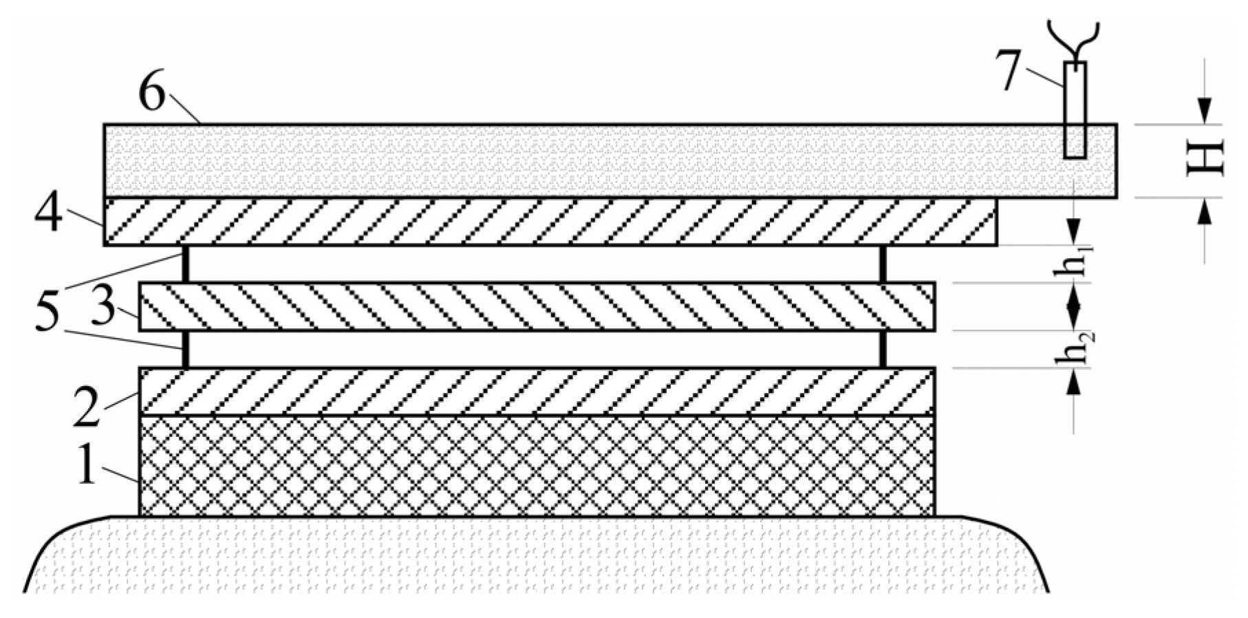
| Material | Layer Thickness, mm | Height of the Explosive, mm | Stand-Off Distance, mm | Vc, m/s | Vi, m/s |
|---|---|---|---|---|---|
| 20880 | 1.5 | 80 | 0.5 | 2000 | 530 |
| AD1 | 0.35 | ||||
| VT1-0 | 3.0 | 2.0 | 590 |
Disclaimer/Publisher’s Note: The statements, opinions and data contained in all publications are solely those of the individual author(s) and contributor(s) and not of MDPI and/or the editor(s). MDPI and/or the editor(s) disclaim responsibility for any injury to people or property resulting from any ideas, methods, instructions or products referred to in the content. |
© 2025 by the authors. Licensee MDPI, Basel, Switzerland. This article is an open access article distributed under the terms and conditions of the Creative Commons Attribution (CC BY) license (https://creativecommons.org/licenses/by/4.0/).
Share and Cite
Bogdanov, A.I.; Kulevich, V.P.; Novikov, R.E.; Shmorgun, V.G. Formation of Intermetallic Coatings on Titanium by Explosive Welding and Subsequent Heat Treatment of the Layered Metal Composite. J. Compos. Sci. 2025, 9, 379. https://doi.org/10.3390/jcs9070379
Bogdanov AI, Kulevich VP, Novikov RE, Shmorgun VG. Formation of Intermetallic Coatings on Titanium by Explosive Welding and Subsequent Heat Treatment of the Layered Metal Composite. Journal of Composites Science. 2025; 9(7):379. https://doi.org/10.3390/jcs9070379
Chicago/Turabian StyleBogdanov, Artem Igorevich, Vitaliy Pavlovich Kulevich, Roman Evgenevich Novikov, and Victor Georgievich Shmorgun. 2025. "Formation of Intermetallic Coatings on Titanium by Explosive Welding and Subsequent Heat Treatment of the Layered Metal Composite" Journal of Composites Science 9, no. 7: 379. https://doi.org/10.3390/jcs9070379
APA StyleBogdanov, A. I., Kulevich, V. P., Novikov, R. E., & Shmorgun, V. G. (2025). Formation of Intermetallic Coatings on Titanium by Explosive Welding and Subsequent Heat Treatment of the Layered Metal Composite. Journal of Composites Science, 9(7), 379. https://doi.org/10.3390/jcs9070379