
Improving the Anchorage in Textile Reinforced Cement Composites by 3D Spacer Connections: Experimental Study of Flexural and Cracking Behaviors


Abstract
1. Introduction
2. Materials and Methods
2.1. Materials Selection and Reinforcement Configurations
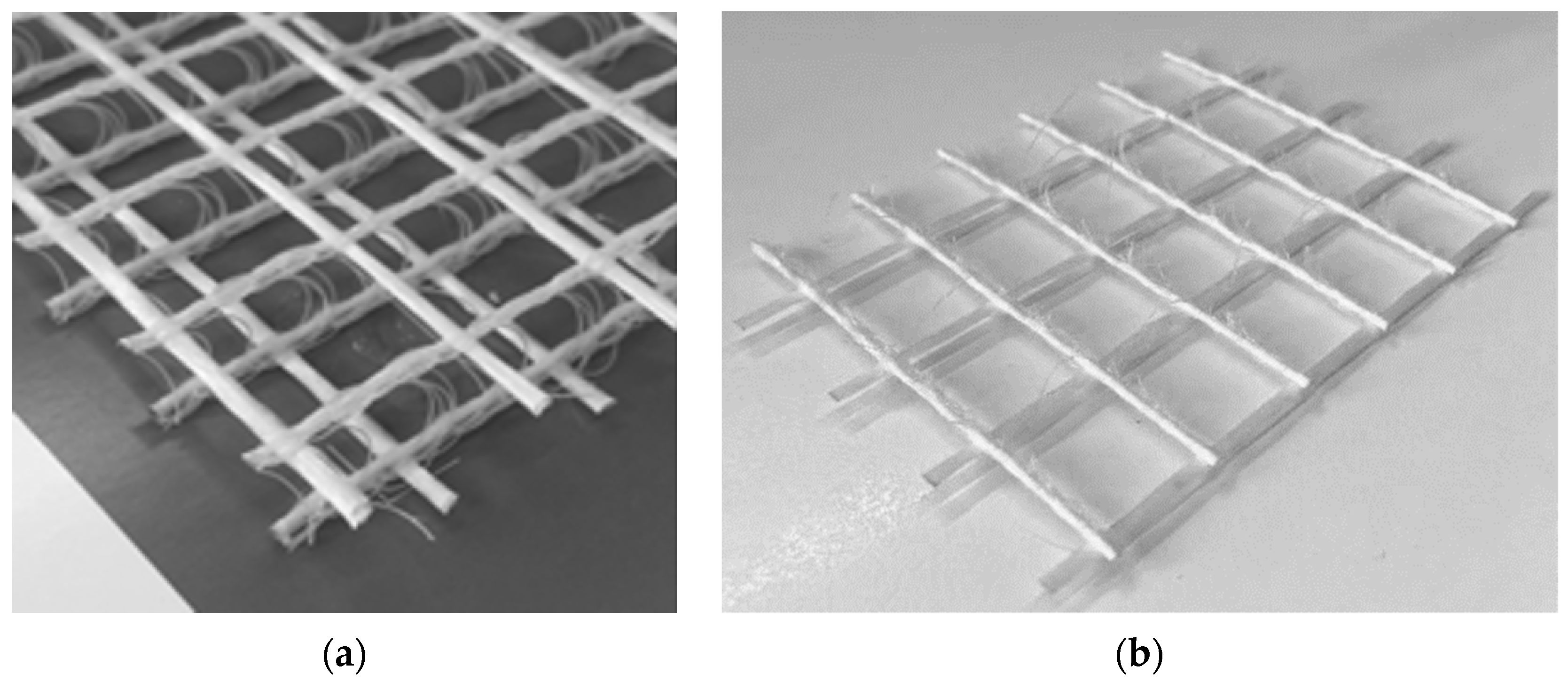
2.1.1. Textiles
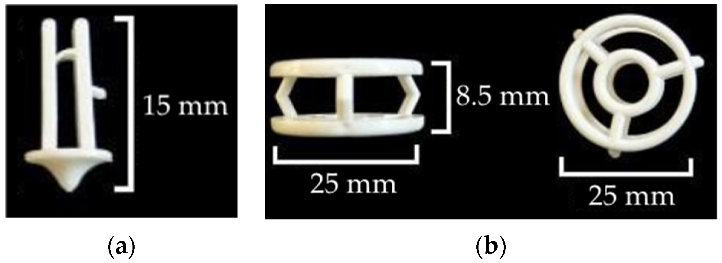
2.1.2. Connections
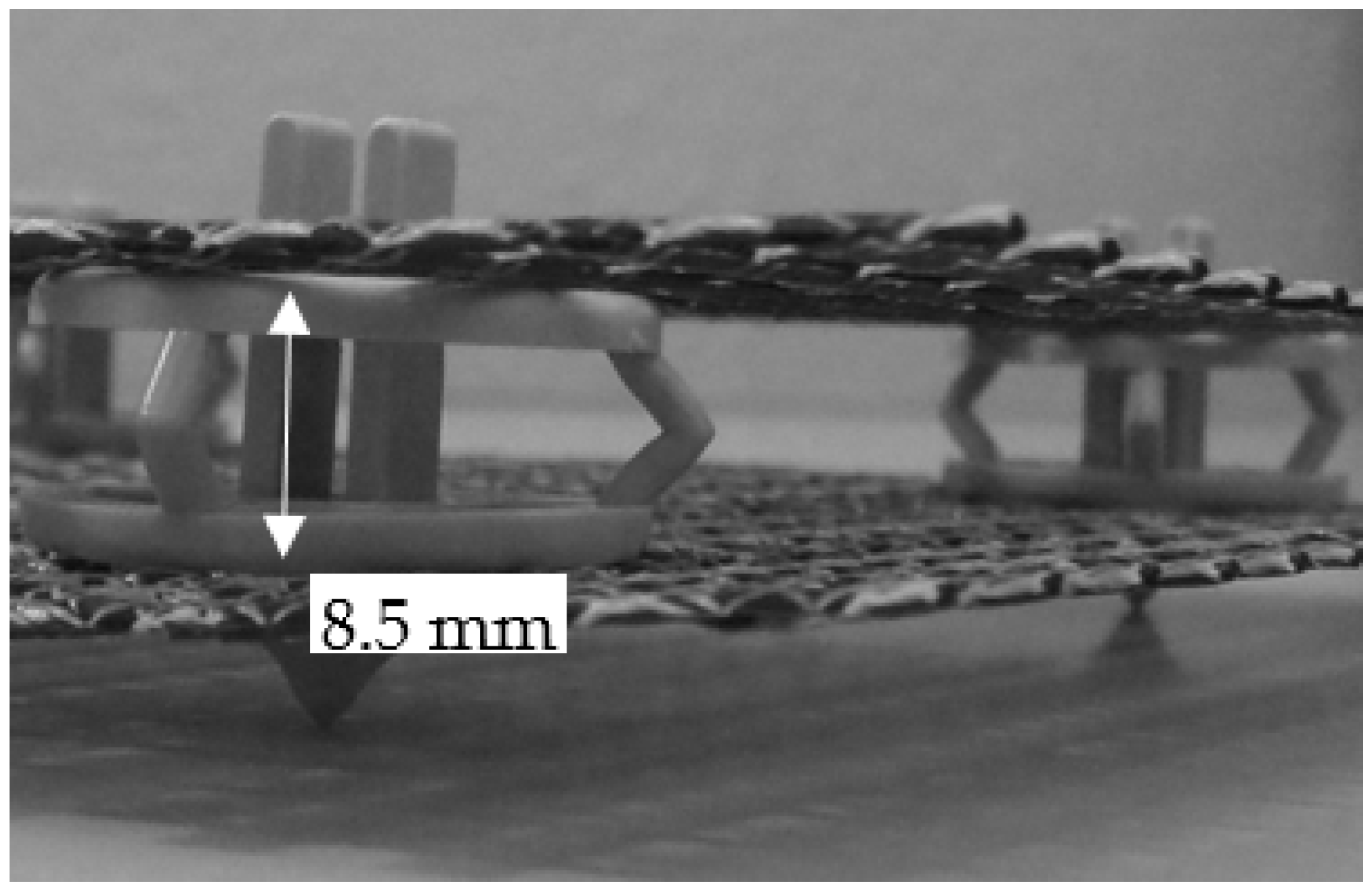
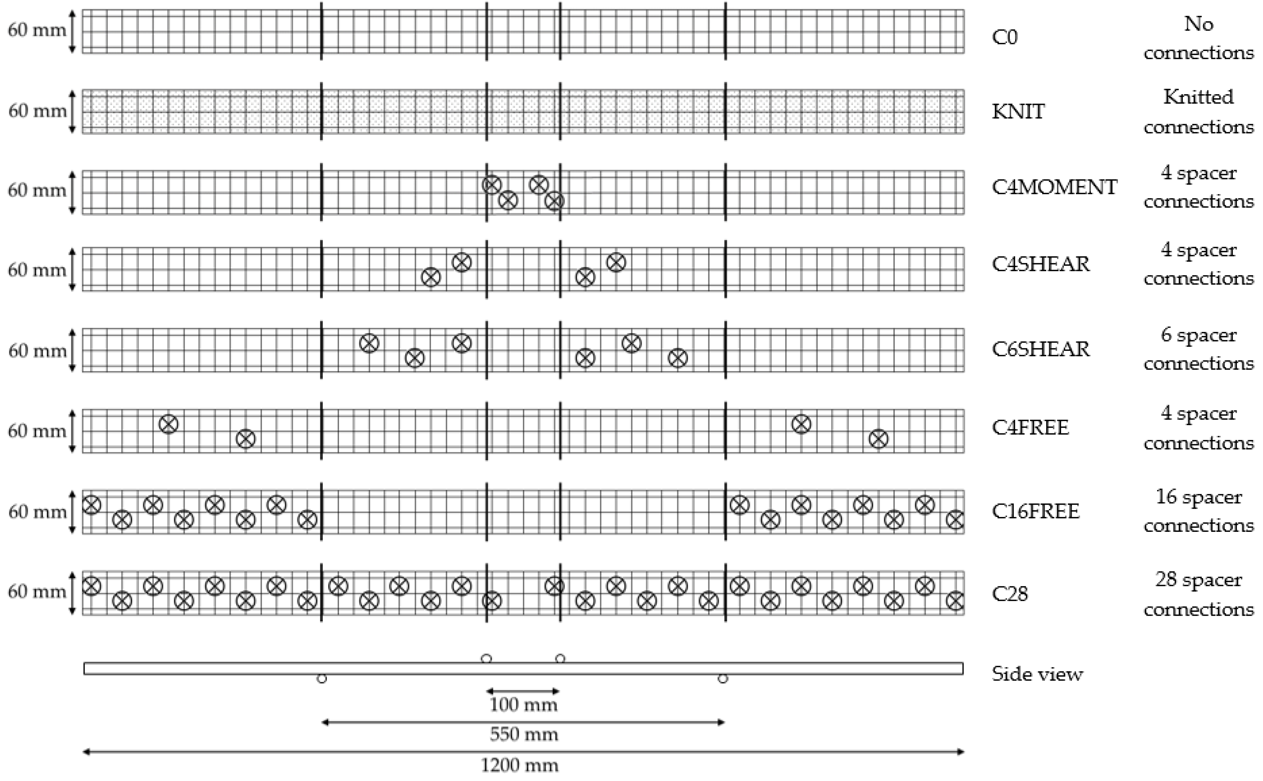
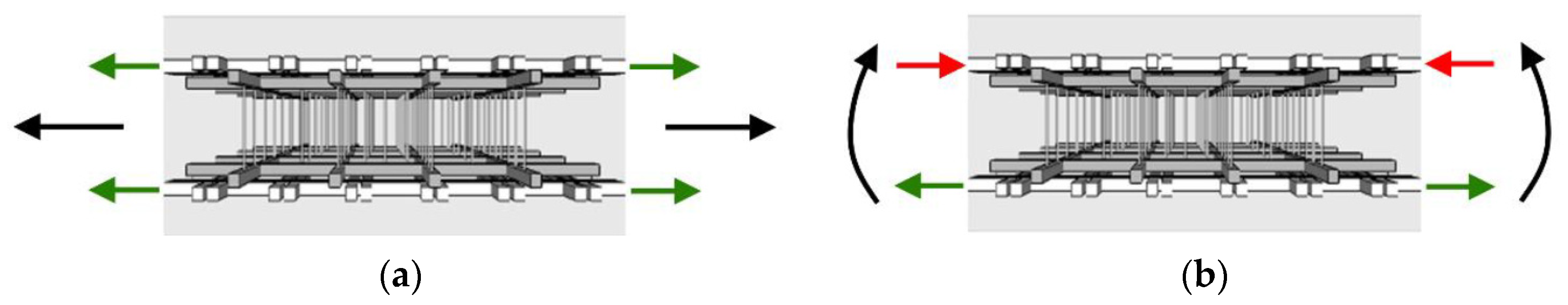
2.1.3. Geometry and Spacer Configurations
2.1.4. Matrix
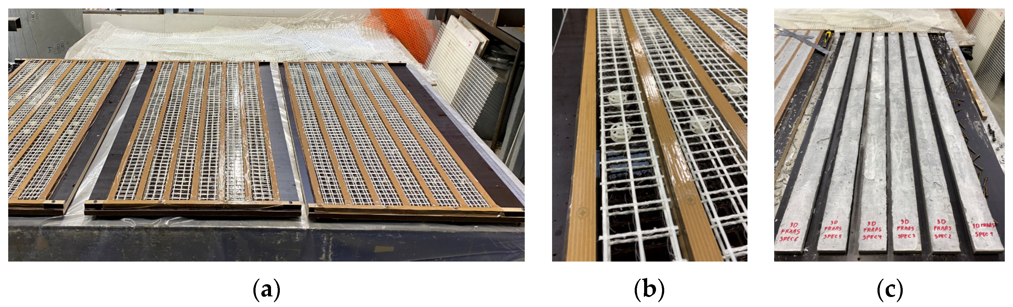
2.2. TRC Manufacturing Process
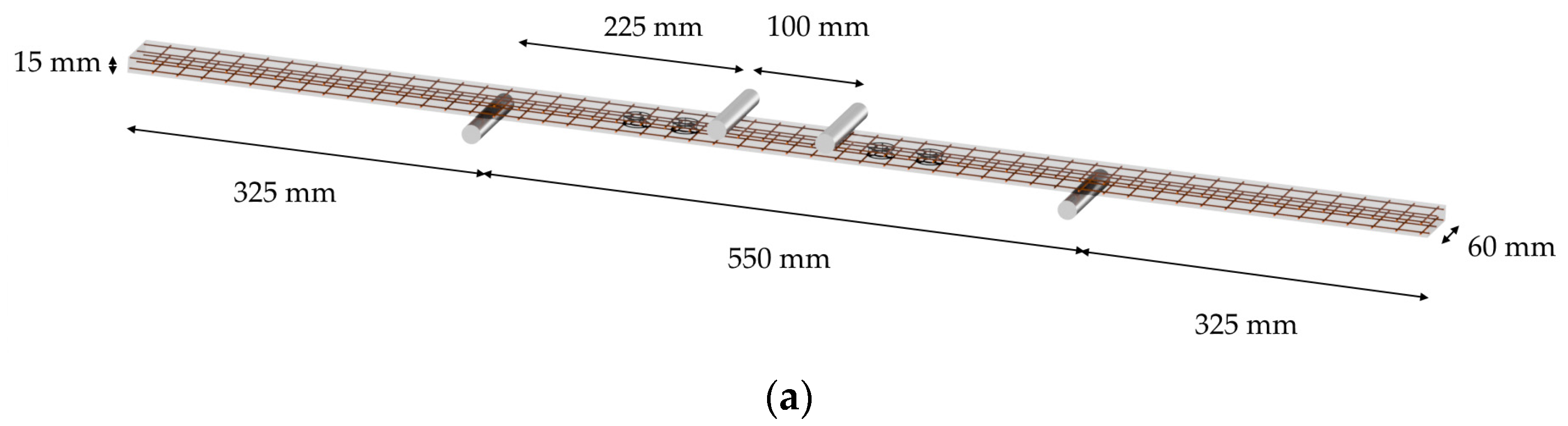
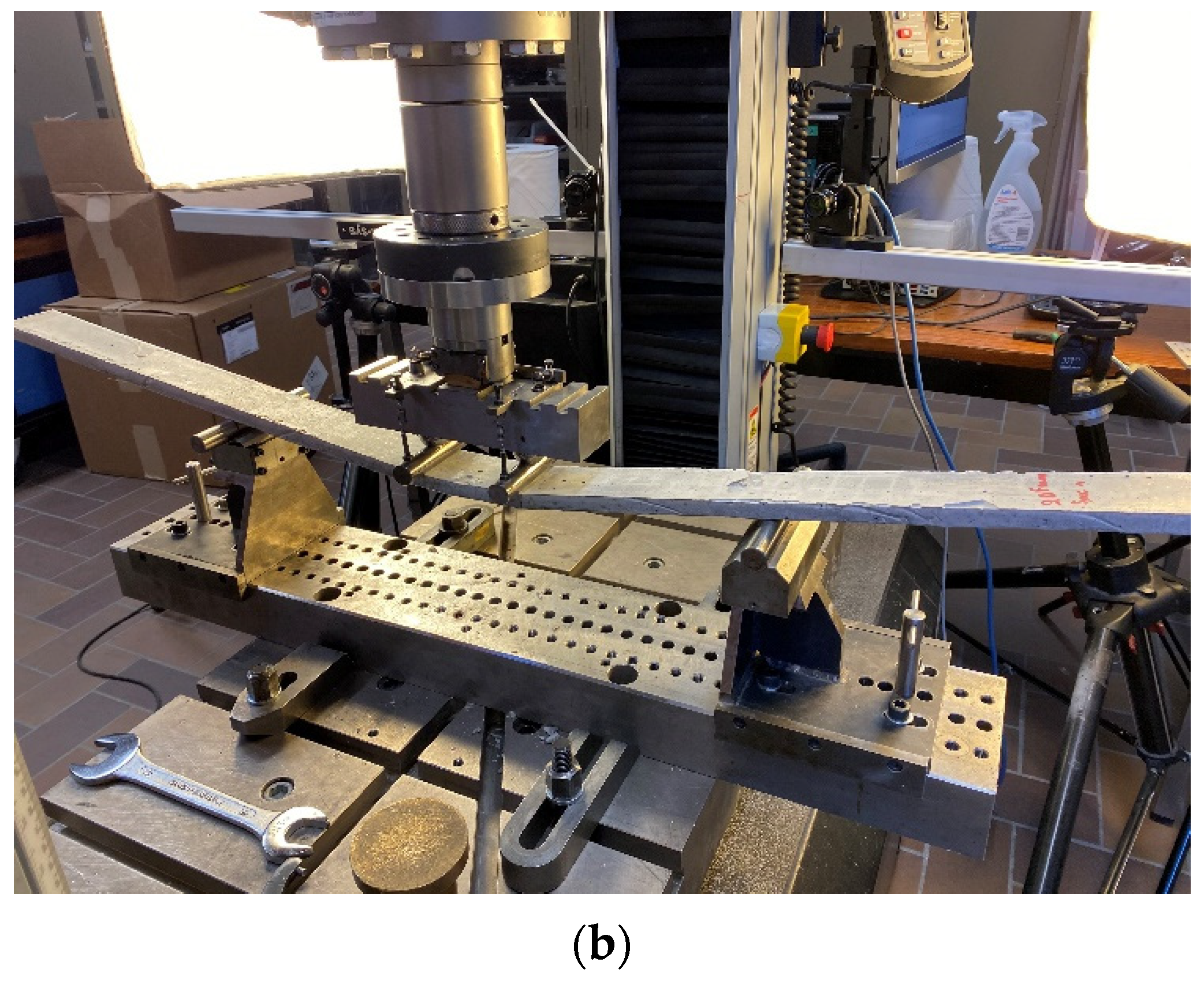
2.3. Experimental Test Setup
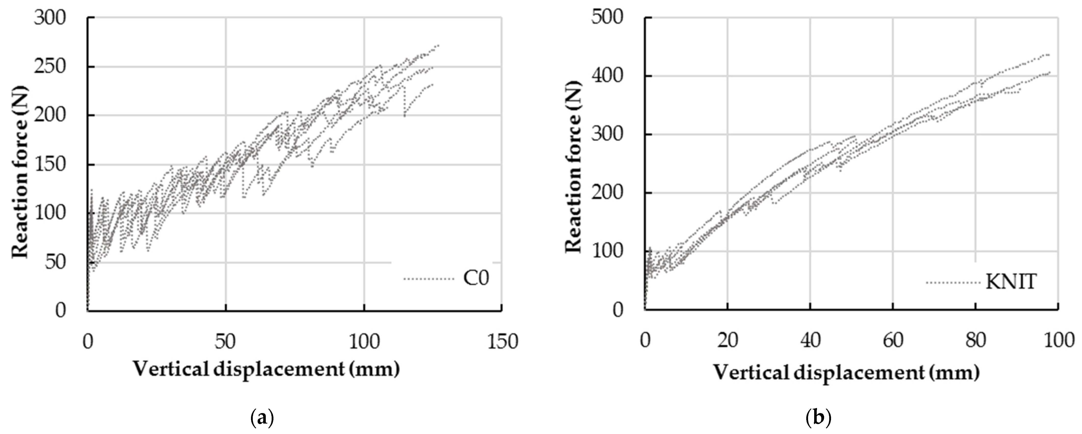
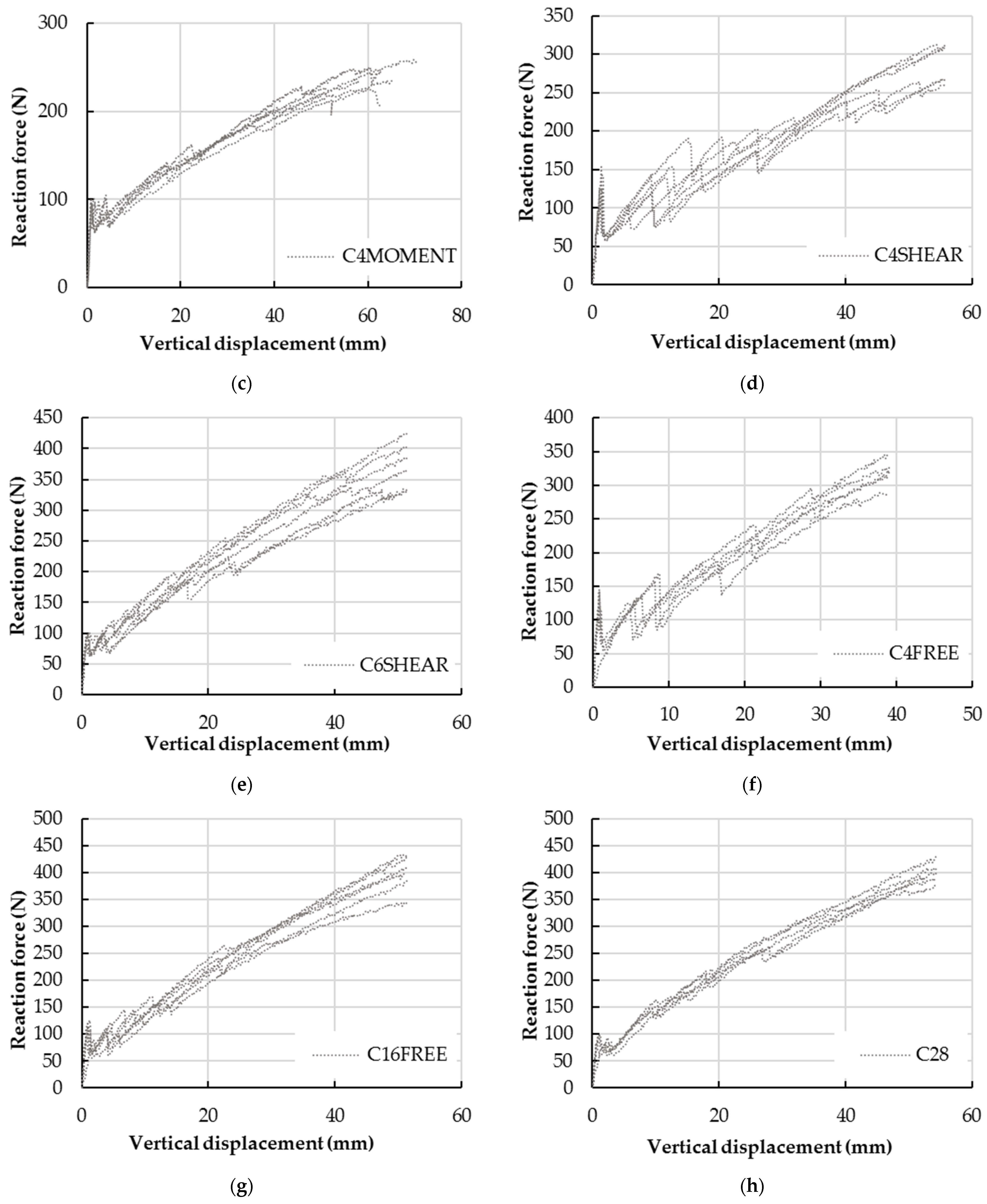
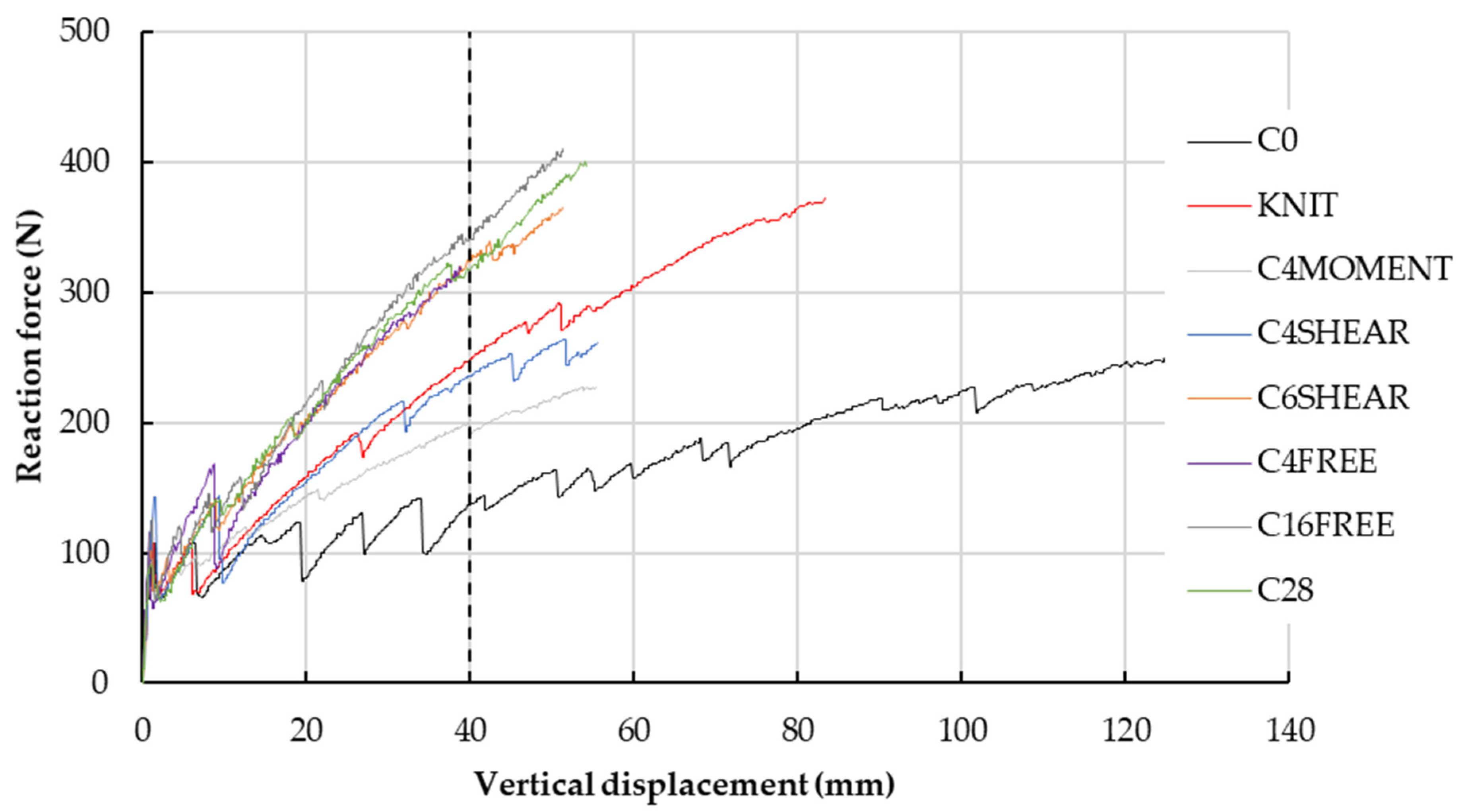
3. Results and Discussion
4. Conclusions
Author Contributions
Funding
Institutional Review Board Statement
Informed Consent Statement
Data Availability Statement
Acknowledgments
Conflicts of Interest
References
- Brameshuber, W. Textile Reinforced Concrete: State of the Art Report. In RILEM Technical Committee 201-TRC, 1st ed.; RILEM Publications: Aachen, Germany, 2006. [Google Scholar]
- Bentur, A.; Mindess, S. Fibre Reinforced Cementitious Composites; Taylor and Francis: New York, NY, USA, 2007; 601p. [Google Scholar]
- Aveston, J.; Cooper, G.A.; Kelly, A. Single and Multiple Fracture. In The Properties of Fibre Composites: Conference Proceedings, National Physical Laboratory, 4 November 1971; IPC Science and Technology Press: Raleigh, NC, USA, 1971; pp. 15–24. [Google Scholar]
- Tomoscheit, S.; Gries, T.; Horstmann, M. Project Life Insu-Shell: Reducing the Carbon Footprint in Concrete Construction. Int. J. Sustain. Build. Technol. Urban Dev. 2011, 2, 162–169. [Google Scholar] [CrossRef]
- Hegger, J.; Kulas, C.; Horstmann, M. Spatial Textile Reinforcement Structures for Ventilated and Sandwich Facade Elements. Adv. Struct. Eng. 2016, 15, 665–675. [Google Scholar] [CrossRef]
- Triantafillou, T.; Papanicolaou, C.G. Shear Strengthening of Reinforced Concrete Members with Textile Reinforced Mortar (TRM) Jackets. Mater. Struct. 2006, 39, 93–103. [Google Scholar] [CrossRef]
- Brückner, A.; Ortlepp, R.; Curbach, M. Anchoring of Shear Strengthening for T-Beams Made of Textile Reinforced Concrete (TRC). Mater. Struct. 2008, 41, 407–418. [Google Scholar] [CrossRef]
- Contamine, R.; Si Larbi, A.; Hamelin, P. Identifying the Contributing Mechanisms of Textile Reinforced Concrete (TRC) in the Case of Shear Repairing Damaged and Reinforced Concrete Beams. Eng. Struct. 2013, 46, 447–458. [Google Scholar] [CrossRef]
- Si Larbi, A.; Agbossou, A.; Hamelin, P. Experimental and Numerical Investigations about Textile-Reinforced Concrete and Hybrid Solutions for Repairing and/or Strengthening Reinforced Concrete Beams. Compos. Struct. 2013, 99, 152–162. [Google Scholar] [CrossRef]
- Verbruggen, S.; Remy, O.; Wastiels, J.; Tysmans, T. Stay-in-Place Formwork of TRC Designed as Shear Reinforcement for Concrete Beams. Adv. Mater. Sci. Eng. 2013, 2013, 648943. [Google Scholar] [CrossRef]
- Peled, A.; Bentur, A.; Mobasher, B. Textile Reinforced Concrete, 1st ed.; CRC Press: Boca Raton, FL, USA, 2017; 473p. [Google Scholar]
- Hegger, J.; Horstmann, M.; Zell, M. Applications for TRC. In Proceedings of the 15th International Congress of the International Glassfibre Reinforced Concrete Association (GRCA), Prague, Czech Republic, 20–23 April 2008. [Google Scholar]
- Tysmans, T.; Adriaenssens, S.; Cuypers, H.; Wastiels, J. Structural Analysis of Small Span Textile Reinforced Concrete Shells with Double Curvature. Compos. Sci. Technol. 2009, 69, 1790–1796. [Google Scholar] [CrossRef]
- Scholzen, A.; Chudoba, R.; Hegger, J. Thin-walled shell structures made of textile-reinforced concrete Part I: Structural design and construction. Struct. Concr. 2015, 16, 106–114. [Google Scholar] [CrossRef]
- Verwimp, E.; Tysmans, T.; Mollaert, M.; Berg, S. Experimental and numerical buckling analysis of a thin TRC dome. Thin-Walled Struct. 2015, 94, 89–97. [Google Scholar] [CrossRef]
- Cuypers, H.; Wastiels, J. Analysis and Verification of the Performance of Sandwich Panels with Textile Reinforced Concrete Faces. J. Sandw. Struct. Mater. 2011, 13, 589–603. [Google Scholar] [CrossRef]
- Vervloet, J.; Tysmans, T.; El Kadi, M.; De Munck, M.; Panagiotis, P.; Van Itterbeek, P.; Wastiels, J.; Van Hemelrijck, D. Validation of a Numerical Bending Model for Sandwich Beams with Textile-Reinforced Cement Faces by Means of Digital Image Correlation. Appl. Sci. 2019, 9, 1253. [Google Scholar] [CrossRef]
- Helbig, T.; Rempel, S.; Unterer, K.; Kulas, C.; Hegger, J. Fuß-und Radwegbrücke aus Carbonbeton in Albstadt-Ebingen. Die weltweit erste ausschließlich carbonfaserbewehrte Betonbrücke. Beton Stahlbetonbau 2016, 111, 676–685. [Google Scholar] [CrossRef]
- Zhu, D.; Mobasher, B.; Peled, A. Experimental study of dynamic behavior of cement-based composites. Constr. Build. Mater. 2011, 25, 1–12. [Google Scholar] [CrossRef]
- Amzaleg, E.; Peled, A.; Janetzko, S.; Gries, T. Flexural Behaviour of Cement Based Element Reinforced with 3D Fabric. In Proceedings of the VIII International Conference on Fracture Mechanics of Concrete and Concrete Structures, Toledo, Spain, 10–14 March 2013. [Google Scholar]
- Peled, A.; Haik, R.; Sasi, E.A. Influence of three-dimensional (3D) fabric orientation on flexural properties of cement-based composites. Cem. Concr. Compos. 2017, 80, 1–9. [Google Scholar]
- El Kadi, M.; Tysmans, T.; Verbruggen, S.; Vervloet, J.; De Munck, M.; Wastiels, J.; Van Hemelrijck, D. Experimental study and benchmarking of 3D textile reinforced cement composites. Cem. Concr. Compos. 2019, 104, 103352. [Google Scholar] [CrossRef]
- El Kadi, M.; Kapsalis, P.; Van Hemelrijck, D.; Wastiels, J.; Tysmans, T. Influence of Loading Orientation and Knitted Versus Woven Transversal connections in 3D Textile Reinforced Cement (TRC) Composites. Appl. Sci. 2020, 10, 4517. [Google Scholar] [CrossRef]
- Ciubanu, L. Development of 3D Knitted Fabrics for Advanced Composite Materials. In Advances in Composite Materials—Ecodesign and Analysis; Intech Open: Rijeka, Croatia, 2011; pp. 161–192. [Google Scholar]
- Roye, A.; Gries, T. 3-D Textiles for Advanced Cement Based Matrix Reinforcement. J. Ind. Text. 2007, 37, 163–173. [Google Scholar] [CrossRef]
- Sutton, M.A.; Orteu, J.-J.; Schreier, H.W. Image Correlation for Shape, Motion and Deformation Measurements; Springer Science Business Media: Berlin/Heidelberg, Germany, 2009. [Google Scholar]
- Fraas, V. Technical Datasheet SitGrid701. Available online: http://www.solutions-in-textile.com (accessed on 1 July 2019).
- DistTEX, CarboCon GmbH. Technical Datasheet DistTex. Available online: https://www.disttex.com (accessed on 1 July 2019).
- Sika. Sikagrout 217, Note de Produit. Available online: https://www.sika.com (accessed on 1 July 2019).
- El Kadi, M.; Tysmans, T.; Verbruggen, S.; Wastiels, J.; Vervloet, J.; De Munck, M.; Van Hemelrijck, D. A layered-wise, composite modelling approach for fibre textile reinforced cementitious composites. Cem. Concr. Compos. 2018, 94, 107–115. [Google Scholar] [CrossRef]
- Triantafillou, T. Textile Fibre Composites in Civil Engineering; Woodhead Publishing: Sawston, UK, 2016; 470p. [Google Scholar]


| Material | Grid Size (mm × mm) | Textile Density Coated (Both Layers) (g/m2) | Textile Density Uncoated (Both Layers) (g/m2) | Coating | Transversal Connection |
|---|---|---|---|---|---|
| AR Glass 2400tex | 22.5 × 22.5 | 614 | 536 | SBR | Polyester PET |
| Aggregate Size (mm) | Compressive Strength (28 d) (MPa) | Flexural Tensile Strength (28 d) (MPa) | Density after Mixing (kg/m3) | Young’s Modulus (GPa) | Water/Mortar Ratio (-) |
|---|---|---|---|---|---|
| 0–1.6 | 70 | 12 | 2010 | 9 | 0.15 |
| Conf. | K3 (N/mm) | MOR (MPa) | Cracking Data at a Vertical Displacement of 40 mm | |||||
|---|---|---|---|---|---|---|---|---|
| # Cracks Total | Crack Width Total (mm) | Crack Spacing Total (mm) | # Cracks Mid | Crack Width Mid (mm) | Crack Spacing Mid (mm) | |||
| C0 | 1.74 ± 0.78 | 11.9 ± 1.2 | 6 | 0.39 ± 0.16 | 46 ± 13 | 2 | 0.56 ± 0.11 | 62.0 ± 0.0 |
| KNIT | 4.40 ± 0.72 | 19.7 ± 2.7 | 7 | 0.38 ± 0.12 | 36 ± 11 | 2 | 0.35 ± 0.10 | 40.31 ± 0.18 |
| C4MOMENT | 2.82 ± 0.52 | 11.93 ± 0.60 | 8 | 0.52 ± 0.29 | 21.7 ± 1.9 | 6 | 0.47 ± 0.18 | 29.8 ± 8.0 |
| C4SHEAR | 3.98 ± 0.78 | 17.5 ± 3.6 | 5 | 0.41 ± 0.23 | 58 ± 20 | 3 | 0.64 ± 0.15 | 40.1 ± 2.0 |
| C6SHEAR | 6.5 ± 1.9 | 20.8 ± 3.4 | 4 | 0.68 ± 0.28 | 35 ± 12 | 4 | 0.68 ± 0.28 | 35 ± 12 |
| C4FREE | 7.0 ± 2.3 | 16.3 ± 6.3 | 2 | 1.608 ± 0.025 | 100 ± 0.0 | 2 | 1.608 ± 0.025 | 100 ± 0.0 |
| C16FREE | 7.1 ± 1.5 | 21.1 ± 2.3 | 3 | 0.92 ± 0.35 | 62.8 ± 7.1 | 3 | 0.92 ± 0.35 | 62.8 ± 7.1 |
| C28 | 6.7 ± 2.1 | 20.7 ± 2.4 | 6 | 0.41 ± 0.17 | 26 ± 13 | 4 | 0.30 ± 0.11 | 19.98 ± 0.31 |
Publisher’s Note: MDPI stays neutral with regard to jurisdictional claims in published maps and institutional affiliations. |
© 2022 by the authors. Licensee MDPI, Basel, Switzerland. This article is an open access article distributed under the terms and conditions of the Creative Commons Attribution (CC BY) license (https://creativecommons.org/licenses/by/4.0/).
Share and Cite
El Kadi, M.; Van Hemelrijck, D.; Tysmans, T. Improving the Anchorage in Textile Reinforced Cement Composites by 3D Spacer Connections: Experimental Study of Flexural and Cracking Behaviors. J. Compos. Sci. 2022, 6, 357. https://doi.org/10.3390/jcs6120357
El Kadi M, Van Hemelrijck D, Tysmans T. Improving the Anchorage in Textile Reinforced Cement Composites by 3D Spacer Connections: Experimental Study of Flexural and Cracking Behaviors. Journal of Composites Science. 2022; 6(12):357. https://doi.org/10.3390/jcs6120357
Chicago/Turabian StyleEl Kadi, Michael, Danny Van Hemelrijck, and Tine Tysmans. 2022. "Improving the Anchorage in Textile Reinforced Cement Composites by 3D Spacer Connections: Experimental Study of Flexural and Cracking Behaviors" Journal of Composites Science 6, no. 12: 357. https://doi.org/10.3390/jcs6120357
APA StyleEl Kadi, M., Van Hemelrijck, D., & Tysmans, T. (2022). Improving the Anchorage in Textile Reinforced Cement Composites by 3D Spacer Connections: Experimental Study of Flexural and Cracking Behaviors. Journal of Composites Science, 6(12), 357. https://doi.org/10.3390/jcs6120357