Article

Modelling and Comparative Analysis of Epoxy-Fly-Ash Composite with Alloys for Bracket Application

by
Abhijay B. Raghunandan
1,
Dundesh S. Chiniwar
1,
Shivashankar Hiremath
1,*,
Pavankumar Sondar
2 and
H. M. Vishwanatha
3,*
1
Department of Mechatronics, Manipal Institute of Technology, Manipal Academy of Higher Education, Manipal, Udupi 576104, India
2
Department of Metallurgical and Materials Engineering, National Institute of Technology Karnataka, Surathkal, Mangalore 575025, India
3
Department of Mechanical and Industrial Engineering, Manipal Institute of Technology, Manipal Academy of Higher Education, Manipal, Udupi 576104, India
*
Authors to whom correspondence should be addressed.
J. Compos. Sci. 2022, 6(12), 358; https://doi.org/10.3390/jcs6120358
Submission received: 2 September 2022 / Revised: 2 October 2022 / Accepted: 24 October 2022 / Published: 23 November 2022
(This article belongs to the Special Issue Advanced Polymeric Composites and Hybrid Materials)

Abstract

:
The current study compares and analyses the fly-ash–epoxy composite structure with alloys for bracket applications. A dispersed reinforcement composite is created by combining epoxy and fly-ash. Three different prototypical brackets are modelled and analysed using the finite element method, and their results are compared to common alloys used in the manufacture of L-shaped brackets. The mechanical properties of the composite material are calculated using a rule of mixtures, and the properties of the composite material are modified by changing the percentage composition of fly-ash. Based on equivalent stress and total deformation, all geometrical models are analysed and compared. The analysis results appear to be appropriate for broadening the scope of the application of epoxy-based composites for small-scale and large-scale applications. The results also show that the composite material can be used to make a variety of structural elements with high design complexity, such as bulkheads and other structural components.

1. Introduction

A bracket is an L-shaped architectural element that, depending on its application, is typically used to provide support to [1,2] a part or a beam. Shelving, countertops, dental brackets, flooring, satellites, and furniture section are the most common application areas [3,4,5,6,7]. Currently, brackets used in household applications are typically made of mild steel, aluminium, copper, or alloys of these metals. These are currently the only materials with large-scale production, which primarily involves sheet metal fabrication [8,9].
L brackets are widely used in construction and building work due to their durability, speed, geometry optimisation, and high performance. Brackets are primarily used to connect, join, hold, and integrate the structure; therefore, a thorough understanding of brackets through modelling with sustainable materials is required. Few researchers have conducted numerical and experimental studies on bracketing behaviour [1,2]. An author investigated the shear and uplift direction behaviour of angle brackets under cyclic loads [10]. Several steel angle brackets were tested for monotonic and reversed cyclic periods, and the results were compared to analytical methods [11]. The brackets ensure that the various components of the building structure are joined tightly. These structures are made of solid wood and cement blocks, and some steel blocks are joined through metallic brackets. When compared to joining the product, these brackets have a relatively high mechanical strength. Several models exist based on the mechanical performance of the brackets [12,13]. These brackets can be used to secure the two structures while also strengthening and stiffening them. The main advantage of these brackets is the material’s durability, which can improve the performance of the blocks.
Different approaches for simulation assembly on L brackets are available in the literature [14,15,16]. In this case, a single component model is required to analyse different geometry and sustainable materials. In experiments, the L brackets connection is frequently loaded in multiple directions. The combination of all load behaviour analyses is critical in the angle bracket. One of the goals of this research is to model a single component with different geometry and analyse its mechanical behaviour.
Epoxy resins, also known as poly-epoxides, have a wide range of applications in industries, such as the automotive and aerospace industries. They can be used as coatings and adhesives, as well as a matrix material in the composite manufacturing process [17]. Polymer matrix composite is a material made up of a polymer matrix (resin) and a dispersed fibrous reinforcing phase. Significant research on polymer matrix composites has been conducted in various industrial fields to improve the strength and electrical properties while reducing weight, primarily through the addition of fillers [18]. The epoxy-fly-ash composite can be considered as a potential replacement for commonly used materials in house-hold applications. Fly-ash is a by-product of coal combustion in thermal power plants. Because of its high strength and low cost, several researchers have used fly-ash as a filler in polymer matrices [19,20,21].
Polymer matrix composites offer high tensile strength, stiffness, abrasion resistance, and corrosion resistance and are relatively cheaper to produce when compared to sheet metal fabrication, which involves heavy machinery leading to higher manufacturing costs [22,23]. The finite element method is the simplest mode for obtaining nearly accurate results. The mesh parameters can be modified in such a way that the maximum number of elements can be obtained without increasing computational time. The objective of this paper is to model a fly-ash-epoxy composite using the finite element method and compare the simulation results with the properties of alloys that are majorly used in the present market. Having cost-effectiveness and ease of fabrication, fly-ash-epoxy composites can replace some of the alloy-made brackets where the load-bearing capacity is lesser.

2. Materials and Methods

The current work focuses primarily on optimising the geometry of the model and comparing epoxy-fly-ash composites with varying fly-ash content. CAD models were created using commercially available CATIA (Dassault Systems) software, and numerical simulations were performed using ANSYS software. Material properties were added to each geometry in ANSYS software after they were built and then optimised meshing and boundary conditions were used for the analysis [14].
Using the mixture rule as the governing equation, different percentages of fly-ash (5%, 10%, and 15% volume fraction) were added to the epoxy matrix. The obtained results are compared in terms of deformation, equivalent stress, and maximum load-carrying capacity [24]. Three geometries were considered for the current work, and because all of the geometries were simple, program-controlled meshing was used. As the prototype model developed is compared to currently available alloy brackets, general properties of commonly available alloys are presented in Table 1 [25,26,27], and epoxy and fly-ash properties are provided in Table 2 [25].

2.1. Calculations

Typical material properties that are required for analysis are density, Poisson ratio, and Young’s modulus or modulus of elasticity. By using the rule of mixture, the properties of the composite material can be calculated from the following Equation (1) [28,29].
Ec = Ef (Vf/Vc) + Em (1 − (Vf/Vc))
where
Ec = Modulus of elasticity of composite;
Ef = Modulus of elasticity of filler (fly-ash);
Vf = Volume of filler;
Em = Modulus of elasticity of matrix (epoxy resin);
Vc = Volume of composite.
Using Equation (1), the properties of the epoxy and fly-ash polymer assembly (EFPA) with varying volume fractions of fly-ash (5, 10, and 15%) were designed. Different geometry models developed for the analysis are shown in Figure 1.

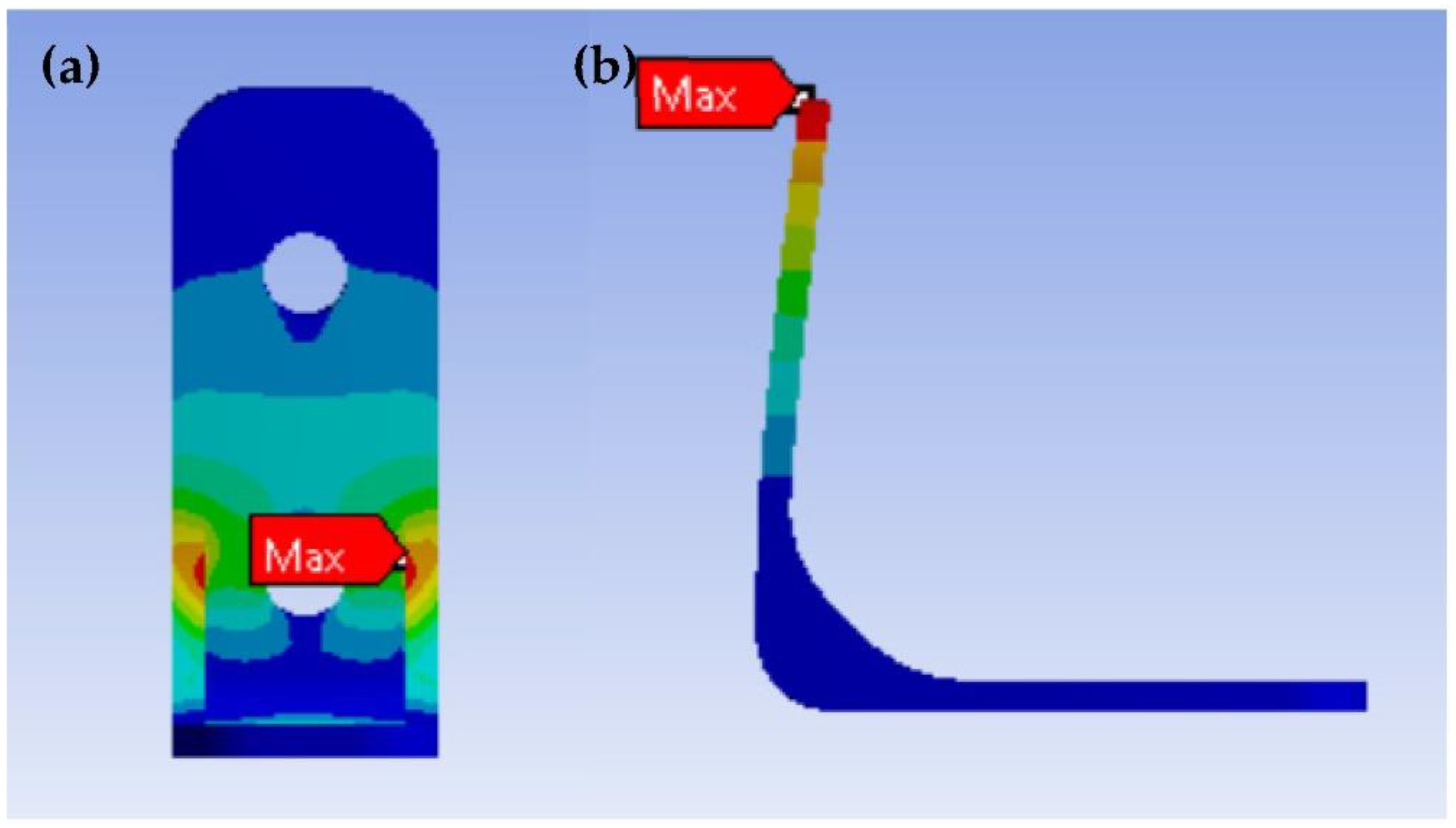
2.2. Numerical Modelling

When compared to experimental testing, numerical modelling is one of the important constituent methods that can provide a faster response to the component. Once the model has been developed and tested under various conditions, then it can be compared to experimental data. One of the authors used the numerical modelling method to assess the load-bearing capacities of the angle bracket [18]. The angle bracket was modelled as a shell element in their model, and the fasteners were modelled as connectors with pre-determined properties. In another case, a load bearing composite bracket was created and analysed for mechanical behaviour and optimisation, demonstrating the effectiveness of using FE as the modelling approach [30].
Different geometries of the finite element model of the L bracket were established in ANSYS to determine the mechanical behaviour of the brackets. The load bearing was performed for the different geometric dimensions of the bracket, the performance of existing alloy material brackets was compared with the epoxy-fly-ash composite, and the maximum values of deflections and stresses were analysed.
The L bracket is studied by establishing various numerical conditions such as boundary conditions and mesh elements. The steps involve connecting the brackets to the surface where the load is to be positioned. Loads were applied from 10 N to 50 N with a 10 N interval for Mode-1 and Mode-2 brackets. In Mode-3, the loads were increased tenfold due to the model’s higher stiffness by design, resulting in a range of 100 N–700 N with 100 N intervals. Because of the presence of gussets, Mode-3 remains an outlier among the other modes. The loading conditions were chosen to allow for the failure of the weakest material, and the load value at which any of the materials failed was chosen as the upper limit.
The bracket is fastened to a surface (usually a wall) with screws or adhesives, and the required object is mounted on the open surface. The applied load is normal to the surface and could be in either direction, but the behaviour is the same. The red area represents where the load is applied, and the blue area represents the fixed support shown in Figure 2. The factor of safety is not a priority in this study because it aims to understand mechanical behaviours and observe the durability of composite materials.
Every time, the mesh settings were fine-tuned with an arbitrary boundary condition, and optimisation was performed on all three geometries. Mesh size function was set to proximity and curvature, and other metrics were slightly modified, such as growth rate being set to 1.2 and span angle centre being set to medium. To obtain satisfactory meshing conditions, the average numbers of elements obtained from Mode-1 to Mode-3 were 17,256, 47,446, and 39,658, respectively, and the mesh quality in all modes was desired to be above 80%. Figure 3 depicts the mesh model of all three brackets derived from the mesh result.

3. Results and Discussion

The L-shaped clamp is designed and simulated to evaluate the strength of the composite material. Three different modes of structures were designed and simulated using ANSYS software. The simulated models are compared with the available alloy materials.
Figure 4 shows the simulation results of the Mode-1 structure of the L-shaped clamp. As expected, the maximum stress was observed at the neck point and deformation was observed at one of the tip positions. It indicates that stress is relieved at both surfaces based on load conditions. Moreover, the maximum deformation occurs at the surface tip, which has a maximum load.
To compare the existing design with the alloy materials, the properties of alloy materials were incorporated into the existing L-shaped clamp model. Figure 5 shows the variation of stress and deformation with varied loading conditions for the Mode-1 clamp. As the load varies from 10 N to 50 N, stresses on the clamp also increase. It is important to note that epoxy and fly-ash polymer assembly (EFPA) composites reach the same stress level with varied load conditions compared to alloy materials. Similarly, the deformation plot shows that maximum deformation occurs at 5% fly-ash composite compared to other alloy materials. The varied volume percentage of the fly-ash in the epoxy composite had a lower deformation effect due to an increase in stiffness.
The second mode of the structure has an additional joint at the neck position of the L-shaped clamp. Figure 6 shows the simulated results of Mode-2, showing maximum stress and deformation. In this case, the stresses are shifted to the additional joint of the L-shaped clamp, and maximum stress occurs at both corners of the additional joint. In this case, the deformation is reduced due to additional joints on the L-shaped clamp. In Mode-2, the load-bearing capacity is increased and deformation is reduced in comparison to Mode-1.
Figure 7 shows the simulation results of Mode-2 with varying fly-ash content and models with different alloys with varying loads (10 N to 60 N). As the load increases, stress on the additional joint of the L-shaped clamp increases with various alloy and composite materials. Similar to Mode-1 the fly-ash/epoxy composite structure in Mode-2 can possess a nearly equal load-bearing capacity in comparison to alloy material. Moreover, the deformation of the composite material is higher than that of the alloy material because the composite material has more flexibility.
To improve the strength of the clamp, the existing structure was modified into a corner joint. FE simulation of the corner joint clamp (Mode-3) is shown in Figure 8. In the modified design, the maximum stress of the clamp is shifted towards the corners of the clamp. Moreover, the stress distribution was observed to be uniform as it is distributed among all the edges of the clamp. The deformation of the corner joint clamp is further reduced, and deformation is relieved towards the surface of the fixed point.
Figure 9 shows the variation of stresses for the modified structure (Mode-3) concerning variation in loads in comparison to alloys. As the geometry of the conventional L-shaped clamp changes to the corner joint, the load-bearing capacity of the L-clamp increases. Even if the load is applied from 100 N to 700 N, the stresses of the composite material on the clamp are very near to alloy materials. Moreover, deformation is very low compared to other modes of geometry. Ultimately, the present study concludes that fly-ash and epoxy composite materials can be used as sustainable materials that can replace the conventional materials used in the clamp structures.

4. Conclusions

In the present work, a clamp/bracket is modelled to replace conventional material with sustainable composite material. Three different geometrical structures were modelled and analysed for their load-bearing behaviour by varying load conditions. Further, the models are compared with the existing alloy materials with similar loading conditions. The FE analysis shows that as the load increases, the stiffness of the clamp increases due to the change in the geometry of the bracket. It is observed that the Mode-3 clamp has a higher load-bearing capacity than the other modes of the clamp. The Mode-3 clamp was found to be 21 times stronger than Mode-1. Epoxy and fly-ash composites are sustainable materials that can replace conventional materials used in the development of brackets/clamps. From FE analysis, it can be adjudged that a varied percentage of epoxy and fly-ash composite has almost the same effect as that of alloy material. Since composite materials are more flexible and durable than the available alloy material, with the same load condition composite material can also bare an equal load, as shown by the alloy material. Moreover, composites are easily available and can be effortlessly used in the fabrication of brackets/clamps. Hence, the present study shows that the epoxy and fly-ash composites are more sustainable materials, in terms of cost, ease of manufacturability, and durability compared to conventional alloy materials.

Author Contributions

Conceptualisation, A.B.R. and S.H.; methodology, D.S.C. and S.H.; software, A.B.R.; validation, S.H., P.S. and H.M.V.; formal analysis, A.B.R. and S.H.; investigation, A.B.R. and S.H.; resources, D.S.C. and S.H.; data curation, P.S.; writing—original draft preparation, S.H. and P.S.; writing—review and editing, S.H., P.S. and H.M.V.; visualisation, D.S.C. and S.H.; supervision, D.S.C. and S.H.; project administration, D.S.C. All authors have read and agreed to the published version of the manuscript.

Funding

This research received no external funding.

Data Availability Statement

Not applicable.

Acknowledgments

The authors acknowledge the Department of Mechatronics, Manipal Institute of Technology, Manipal Academy of Higher Education, Manipal, Karnataka, for providing the simulation facility.

Conflicts of Interest

The authors declare no conflict of interest.

References

  1. Kržan, M.; Azinović, B. Cyclic Response of Insulated Steel Angle Brackets Used for Cross-Laminated Timber Connections. Eur. J. Wood Wood Prod. 2021, 79, 691–705. [Google Scholar] [CrossRef]
  2. Rezvani, S.; Zhou, L.; Ni, C. Experimental Evaluation of Angle Bracket Connections in CLT Structures under In- and out-of-Plane Lateral Loading. Eng. Struct. 2021, 244, 112787. [Google Scholar] [CrossRef]
  3. Samal, S.K.; Vishwanatha, H.M.; Saxena, K.K.; Behera, A.; Nguyen, T.A.; Behera, A.; Prakash, C.; Dixit, S.; Mohammed, K.A. 3D-Printed Satellite Brackets: Materials, Manufacturing and Applications. Crystals 2022, 12, 1148. [Google Scholar] [CrossRef]
  4. Botkin, K.J. Shelving Systems and Components Therefor. U.S. Patent US20100000449A1, 7 January 2010. [Google Scholar]
  5. Dhulia, J.K.; Maniar, N.P. Design, Modelling and Manufacturing of 16 Cylinder Hydraulic Fixture with Automated Clamping System. J. Phys. Conf. Ser. 2019, 1240, 012036. [Google Scholar] [CrossRef]
  6. Shoghi, K.; Barrans, S.M.; Rao, H. V Stress in V-Section Band Clamps. Proc. Inst. Mech. Eng. Part C J. Mech. Eng. Sci. 2004, 218, 251–261. [Google Scholar] [CrossRef] [Green Version]
  7. Linjawi, A.I.; Hashim, H.A. The Effect of Volatile Oils on De-Bonding of Polycarbonate Bracket Reinforced with Ceramic Filler: A Quantitative Study (Part 1). Eur. J. Dent. Oral Health 2022, 3, 1–8. [Google Scholar] [CrossRef]
  8. Gillberg, L.; Sandberg, C. Developing Design Guidelines for Load Carrying Sheet Metal Components with Regards to Manufacturing Method. Master’s Thesis, Production Engineering, School of Industrial Engineering and Management (ITM), KTH, Stockholm, Sweden, 2017. [Google Scholar]
  9. Ferchow, J.; Bühler, M.; Schlüssel, M.; Zumofen, L.; Klahn, C.; Hofmann, U.; Kirchheim, A.; Meboldt, M. Design and Validation of a Sheet Metal Clamping System for Additive Manufacturing and Post-Processing. Int. J. Adv. Manuf. Technol. 2022, 119, 7947–7967. [Google Scholar] [CrossRef]
  10. Gavric, I.; Fragiacomo, M.; Ceccotti, A. Cyclic Behaviour of Typical Metal Connectors for Cross-Laminated (CLT) Structures. Mater. Struct. 2015, 48, 1841–1857. [Google Scholar] [CrossRef]
  11. Roberto, T.; Ian, S. Experimental Characterization of Monotonic and Cyclic Loading Responses of CLT Panel-To-Foundation Angle Bracket Connections. J. Mater. Civ. Eng. 2015, 27, 4014189. [Google Scholar] [CrossRef]
  12. D’Arenzo, G.; Rinaldin, G.; Fossetti, M.; Fragiacomo, M. An Innovative Shear-Tension Angle Bracket for Cross-Laminated Timber Structures: Experimental Tests and Numerical Modelling. Eng. Struct. 2019, 197, 109434. [Google Scholar] [CrossRef]
  13. Lukacs, I.; Björnfot, A.; Tomasi, R. Strength and Stiffness of Cross-Laminated Timber (CLT) Shear Walls: State-of-the-Art of Analytical Approaches. Eng. Struct. 2019, 178, 136–147. [Google Scholar] [CrossRef]
  14. Rezvani, S.; Zhou, L. Numerical Modelling Analysis of Angle Bracket Connections Used in Cross Laminated Timber Constructions. Modul. Offsite Constr. Summit Proc. 2019, 421–428. [Google Scholar] [CrossRef] [Green Version]
  15. Luca, P.; Roberto, S. Influence of Wall Assembly on Behaviour of Cross-Laminated Timber Buildings. Proc. Inst. Civ. Eng. Struct. Build. 2015, 168, 275–286. [Google Scholar] [CrossRef]
  16. Pozza, L.; Saetta, A.; Savoia, M.; Talledo, D. Angle Bracket Connections for CLT Structures: Experimental Characterization and Numerical Modelling. Constr. Build. Mater. 2018, 191, 95–113. [Google Scholar] [CrossRef]
  17. Jin, F.-L.; Li, X.; Park, S.-J. Synthesis and Application of Epoxy Resins: A Review. J. Ind. Eng. Chem. 2015, 29, 1–11. [Google Scholar] [CrossRef]
  18. Hiremath, S.; Shrishail, H.M.; Kulkarni, S.M. Progression and Characterization of Polydimethylsiloxane-Carbon Black Nanocomposites for Photothermal Actuator Applications. Sens. Actuators A Phys. 2021, 319, 112522. [Google Scholar] [CrossRef]
  19. Sim, J.; Kang, Y.; Kim, B.J.; Park, Y.H.; Lee, Y.C. Preparation of Fly Ash/Epoxy Composites and Its Effects on Mechanical Properties. Polymers 2020, 12, 79. [Google Scholar] [CrossRef] [Green Version]
  20. Kishore; Kulkarni, S.M.; Sharathchandra, S.; Sunil, D. On the Use of an Instrumented Set-up to Characterize the Impact Behaviour of an Epoxy System Containing Varying Fly Ash Content. Polym. Test. 2002, 21, 763–771. [Google Scholar] [CrossRef] [Green Version]
  21. Chand, N. SEM Observation of Fractured Flyash-Polyester Composites. J. Mater. Sci. Lett. 1988, 7, 36–38. [Google Scholar] [CrossRef]
  22. Wang, R.M.; Zheng, S.R.; Zheng, Y.P. Polymer Matrix Composites and Technology; Woodhead Publishing Series in Composites Science and Engineering; Elsevier Science: Amsterdam, The Netherlands, 2011; ISBN 9780857092212. [Google Scholar]
  23. Rajak, D.K.; Pagar, D.D.; Kumar, R.; Pruncu, C.I. Recent Progress of Reinforcement Materials: A Comprehensive Overview of Composite Materials. J. Mater. Res. Technol. 2019, 8, 6354–6374. [Google Scholar] [CrossRef]
  24. Silori, P.; Shaikh, A.; Kumar, K.C.N.; Tandon, T. Finite Element Analysis of Traction Gear Using ANSYS. Mater. Today Proc. 2015, 2, 2236–2245. [Google Scholar] [CrossRef]
  25. Wollmann, M.; Kiese, J.; Wagner, L. Properties and Applications of Titanium Alloys in Transport. In Proceedings of the 12th World Conference on Titanium, Beijing, China, 19–24 June 2011; Volume 2, pp. 837–844. [Google Scholar]
  26. Baddoo, N.R. Stainless Steel in Construction: A Review of Research, Applications, Challenges and Opportunities. J. Constr. Steel Res. 2008, 64, 1199–1206. [Google Scholar] [CrossRef]
  27. Jayasathyakawin, S.; Ravichandran, M.; Baskar, N.; Chairman, C.A.; Balasundaram, R. Mechanical Properties and Applications of Magnesium Alloy—Review. Mater. Today Proc. 2020, 27, 909–913. [Google Scholar] [CrossRef]
  28. Sathish, T.; Dinesh Kumar, S.; Karthick, S. Modelling and Analysis of Different Connecting Rod Material through Finite Element Route. Mater. Today Proc. 2020, 21, 971–975. [Google Scholar] [CrossRef]
  29. Gautam, A. Static Stress Analysis of Connecting Rod Using Finite Element Approach. IOSR J. Mech. Civ. Eng. 2013, 10, 47–51. [Google Scholar] [CrossRef]
  30. Akhmadullina, G.; Shmelev, G.; Antonov, A.; Gimazetdinov, A.; Fahrutdinov, R. Numerical Modeling and Optimization of Geometric Parameters of a Composite Bracket. IOP Conf. Ser. Mater. Sci. Eng. 2020, 890, 12051. [Google Scholar] [CrossRef]
Figure 1. Different CAD models of brackets were developed for comparison.
Jcs 06 00358 g001
Figure 2. Shows the boundary conditions of all three models of the brackets.
Jcs 06 00358 g002
Figure 3. Shows the mesh model of all three brackets.
Jcs 06 00358 g003
Figure 4. Simulation results of Mode-1 showing (a) maximum stress and (b) maximum deformation.
Jcs 06 00358 g004
Figure 5. Graphs of Mode-1 showing (a) maximum stress vs. load and (b) maximum deformation vs. load.
Jcs 06 00358 g005
Figure 6. Simulation results of Mode-2 showing (a) maximum stress and (b) maximum deformation.
Jcs 06 00358 g006
Figure 7. Graphs of Mode-2 showing (a) maximum stress vs. load and (b) maximum deformation vs. load.
Jcs 06 00358 g007
Figure 8. Simulation results of Mode-3 showing (a) maximum stress and (b) maximum deformation.
Jcs 06 00358 g008
Figure 9. Graphs of Mode-3 showing (a) maximum stress vs. load and (b) maximum deformation vs. load.
Jcs 06 00358 g009
Table 1. Most commonly available alloys and their properties.
MaterialDensity (kg/m−3)Youngs Modulus (GPa)Poisson Ratio
Stainless steel77501930.31
Magnesium alloy1800450.35
Titanium alloy4620960.36
Aluminum alloy2770710.33
Table 2. Properties of fly-ash and epoxy material.
MaterialDensity (kg/m−3)Youngs Modulus (GPa)Compressive Modulus (GPa)Poisson Ratio
Fly-ash118098-0.2
Epoxy12003.22.80.3
Publisher’s Note: MDPI stays neutral with regard to jurisdictional claims in published maps and institutional affiliations.

