
An Overview of the Design of Chitosan-Based Fiber Composite Materials


Abstract
1. Introduction
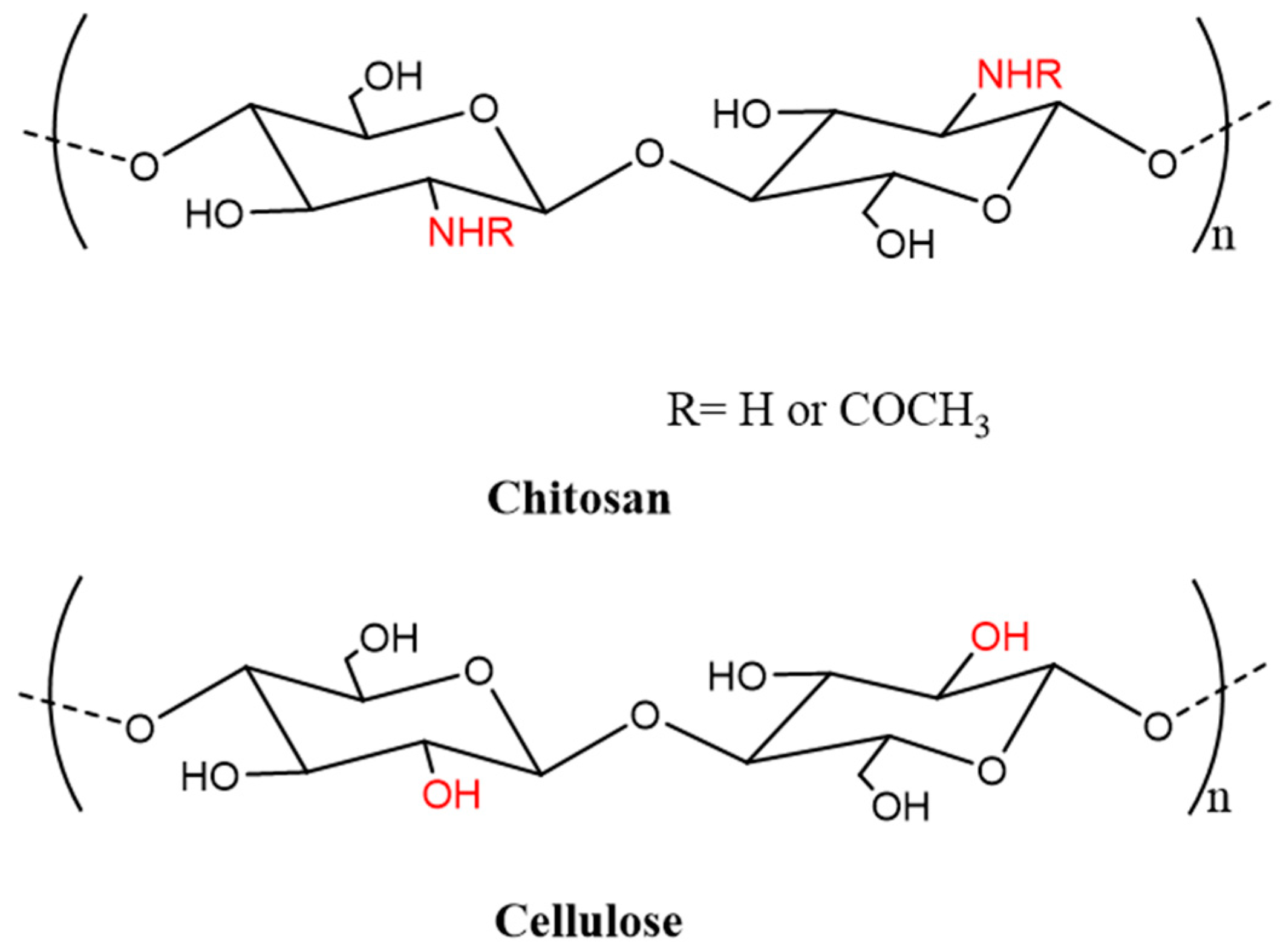
1.1. Chitosan
1.2. Chitosan Composite Fibers
2. Preparation Procedures and Methods
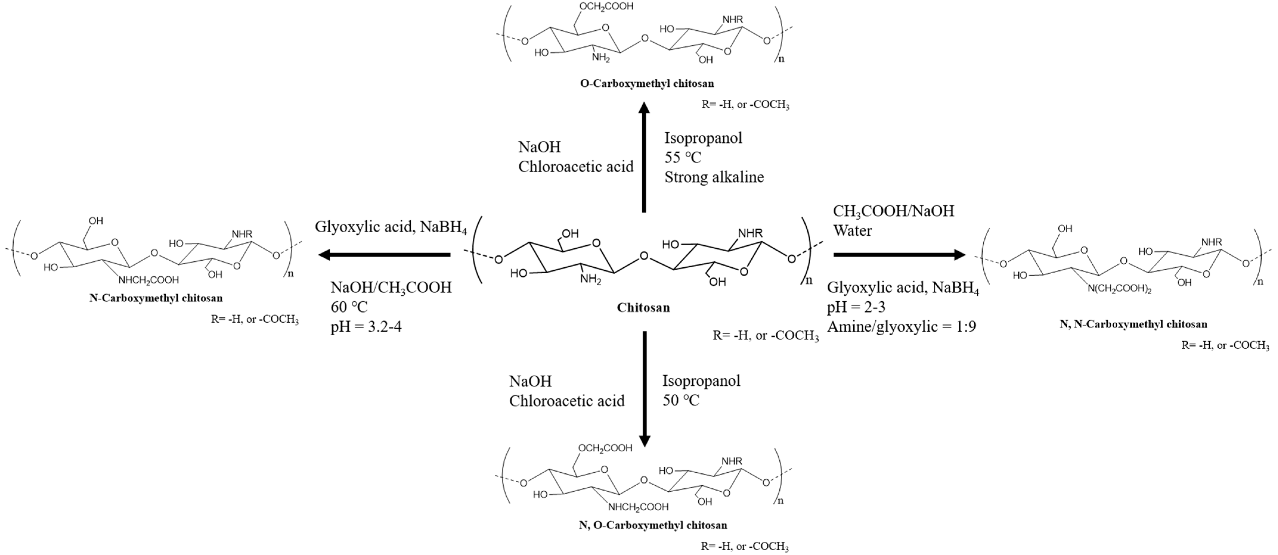
2.1. Modification of Chitosan
2.2. Freeze-Drying Method
2.2.1. Background of the Freeze-Drying Method
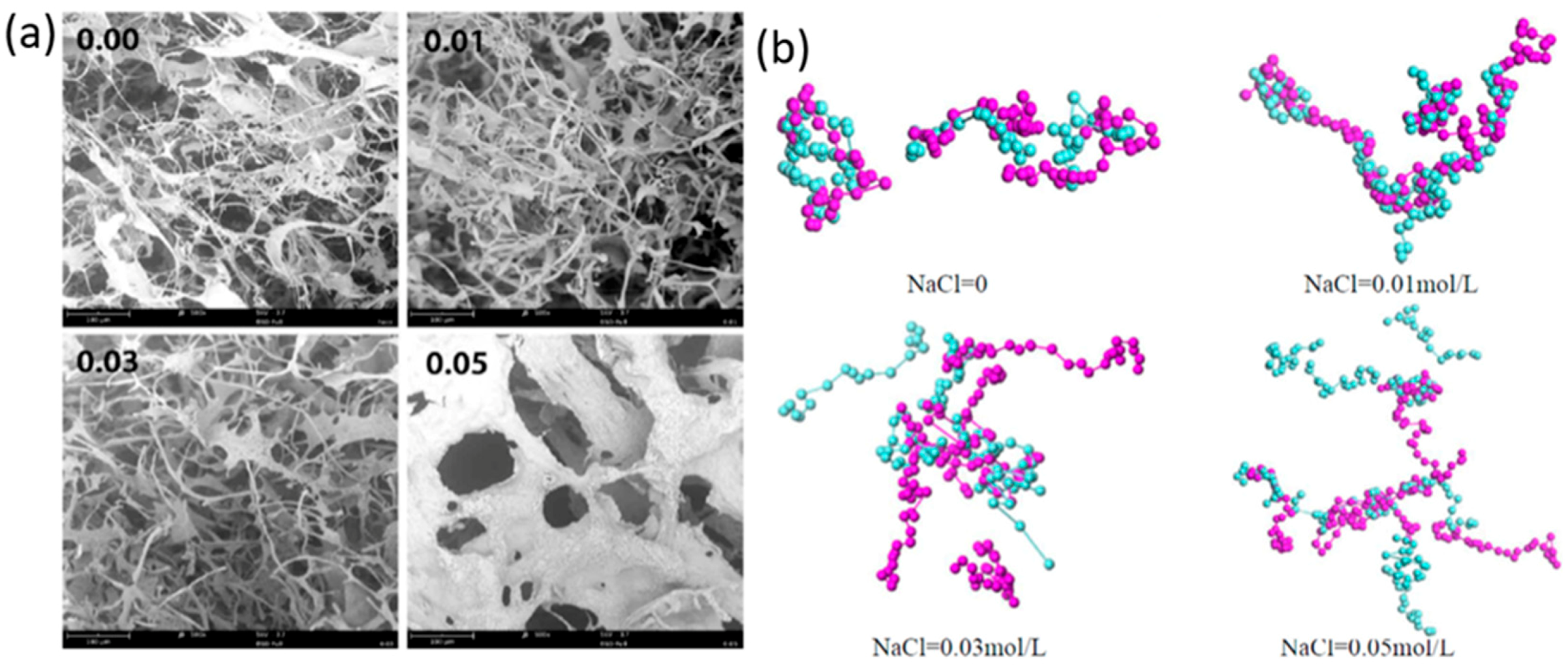
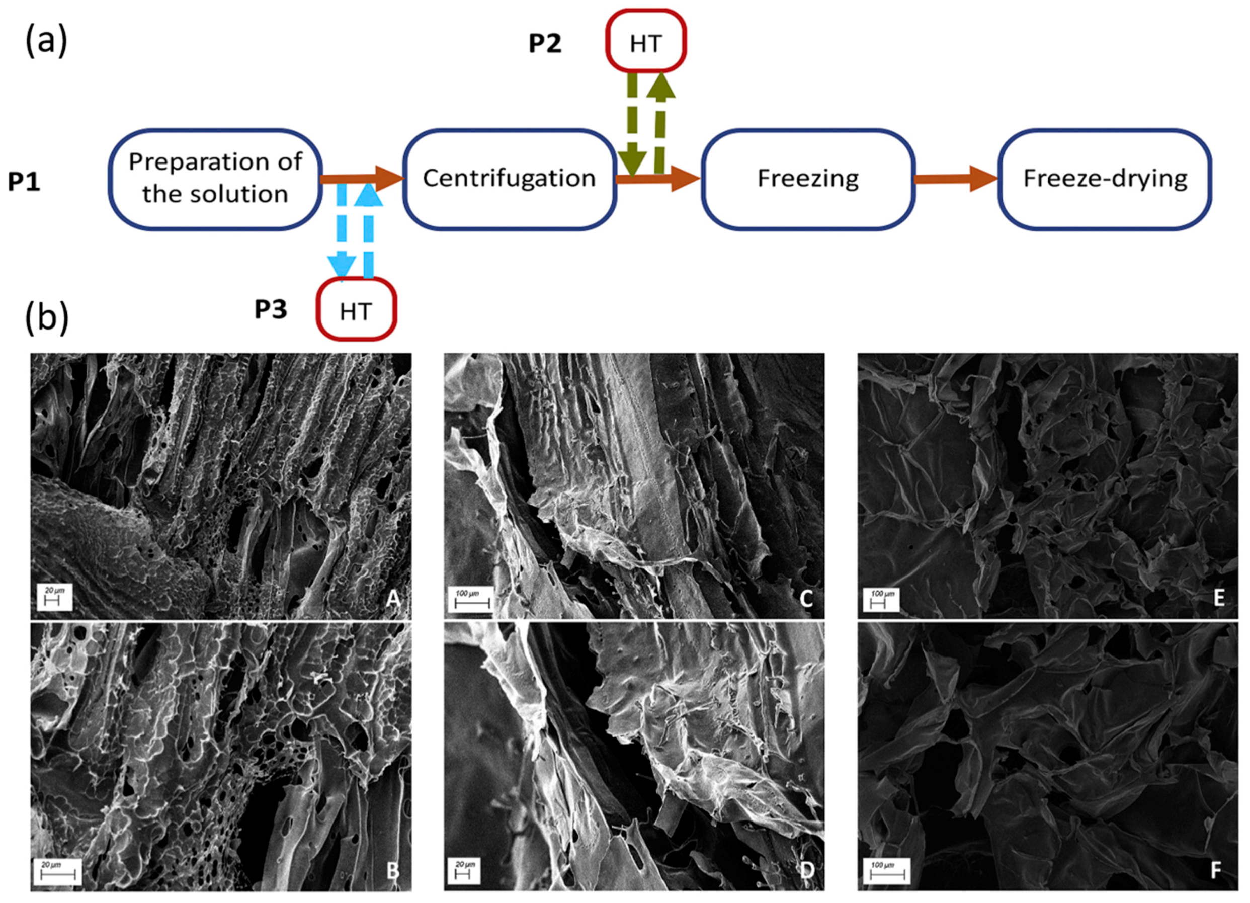
2.2.2. Recent Development on Preparation of Freeze-Dried Chitosan Composites
2.3. Electrospinning Method
2.3.1. Brief History of Electrospinning
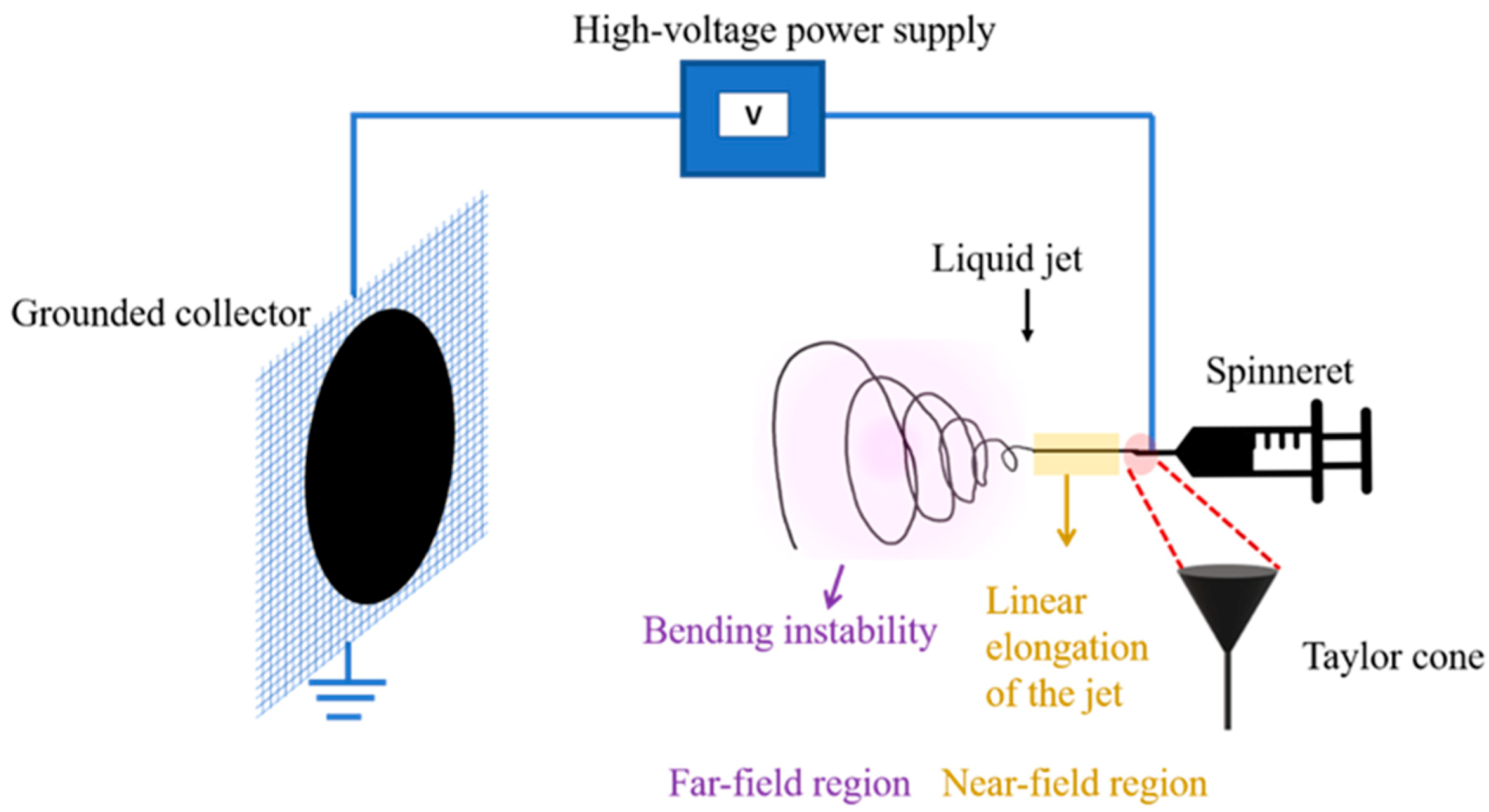
2.3.2. Basic Theory of Electrospinning
2.3.3. Examples of Different Notions for Electrospinning
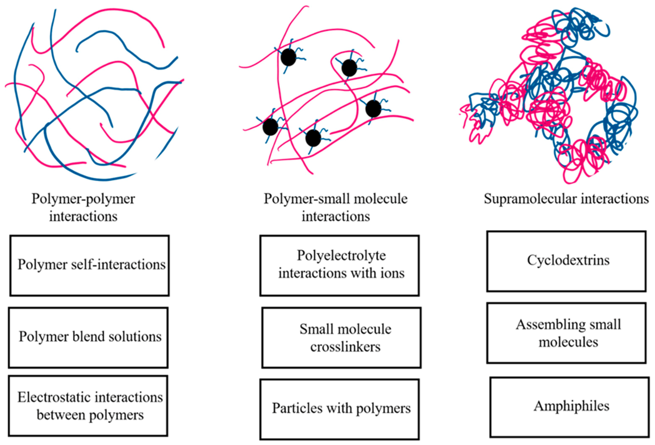
2.3.4. Polymer–Polymer Interactions
2.3.5. Supramolecular Interactions in Cyclodextrin-Based Systems
2.4. Post-Treatment Methods
2.4.1. Purpose of Post-Treatment
2.4.2. Emerging Approaches
Cinnamaldehyde as a Cross-Linking Agent
Coagulant Bath Combined with Physical Cross-Linking via Phosphate Ions
Thermal Treatment Combined with Chemical Cross-Linking
3. Future Perspectives and Concluding Remarks
3.1. Recent Developments on the Preparation Procedures of Chitosan Composites
3.2. Future Perspectives
3.3. Conclusions
Author Contributions
Funding
Institutional Review Board Statement
Informed Consent Statement
Data Availability Statement
Acknowledgments
Conflicts of Interest
References
- De Oliveira, A.M.; Franco, T.T.; Junior, E.N.D.O. Physicochemical Characterization of Thermally Treated Chitosans and Chitosans Obtained by Alkaline Deacetylation. Int. J. Polym. Sci. 2014, 2014, 1–9. [Google Scholar] [CrossRef]
- Younes, I.; Rinaudo, M. Chitin and Chitosan Preparation from Marine Sources. Structure, Properties and Applications. Mar. Drugs 2015, 13, 1133–1174. [Google Scholar] [CrossRef] [PubMed]
- Kakoria, A.; Sinha-Ray, S. A Review on Biopolymer-Based Fibers via Electrospinning and Solution Blowing and Their Applications. Fibers 2018, 6, 45. [Google Scholar] [CrossRef]
- Pillai, C.; Paul, W.; Sharma, C.P. Chitin and chitosan polymers: Chemistry, solubility and fiber formation. Prog. Polym. Sci. 2009, 34, 641–678. [Google Scholar] [CrossRef]
- Sakkara, S.; Santosh, M.S.; Reddy, N. Chitosan Fibers. In Handbook of Fibrous Materials; Wiley: Weinheim, Germany, 2020; pp. 125–156. [Google Scholar]
- Rinaudo, M.; Domard, A. Solution Properties of Chitosan. In Chitin and Chitosan; Skjak-Braek, G., Anthonsen, T., Sandford, P.A., Eds.; Springer: Dordrecht, The Netherlands, 1989; pp. 71–86. ISBN 9781851663958. [Google Scholar]
- Jaworska, M.; Sakurai, K.; Gaudon, P.; Guibal, E. Influence of chitosan characteristics on polymer properties. I: Crystallographic properties. Polym. Int. 2003, 52, 198–205. [Google Scholar] [CrossRef]
- Wang, Q.Z.; Chen, X.G.; Liu, N.; Wang, S.X.; Liu, C.; Meng, X.H. Protonation constants of chitosan with different molecular weight and degree of deacetylation. Carbohydr. Polym. 2006, 65, 194–201. [Google Scholar] [CrossRef]
- Barikani, M.; Oliaei, E.; Seddiqi, H.; Honarkar, H. Preparation and application of chitin and its derivatives: A review. Iran. Polym. J. 2014, 23, 307–326. [Google Scholar] [CrossRef]
- Hajji, S.; Younes, I.; Ghorbel-Bellaaj, O.; Hajji, R.; Rinaudo, M.; Nasri, M.; Jellouli, K. Structural differences between chitin and chitosan extracted from three different marine sources. Int. J. Biol. Macromol. 2014, 65, 298–306. [Google Scholar] [CrossRef]
- Aiba, S.-I. Studies on chitosan: 3. Evidence for the presence of random and block copolymer structures in partially N-acetylated chitosans. Int. J. Biol. Macromol. 1991, 13, 40–44. [Google Scholar] [CrossRef]
- Lim, L.-T.; Mendes, A.C.; Chronakis, I.S. Electrospinning and Electrospraying Technologies for Food Applications. In Advances in Food and Nutrition Research; Academic Press: Cambridge, MA, USA, 2019; Volume 88, pp. 167–234. ISBN 9780128160732. [Google Scholar]
- Youssef, A.M.; El-Sayed, S.M. Bionanocomposites materials for food packaging applications: Concepts and future outlook. Carbohydr. Polym. 2018, 193, 19–27. [Google Scholar] [CrossRef] [PubMed]
- Elsabee, M.Z.; Abdou, E.S. Chitosan based edible films and coatings: A review. Mater. Sci. Eng. C 2013, 33, 1819–1841. [Google Scholar] [CrossRef]
- Ahmed, S.; Annu; Ali, A.; Sheikh, J. A review on chitosan centred scaffolds and their applications in tissue engineering. Int. J. Biol. Macromol. 2018, 116, 849–862. [Google Scholar] [CrossRef]
- Ma, G.; Liu, Y.; Peng, C.; Fang, D.; He, B.; Nie, J. Paclitaxel loaded electrospun porous nanofibers as mat potential application for chemotherapy against prostate cancer. Carbohydr. Polym. 2011, 86, 505–512. [Google Scholar] [CrossRef]
- Rieger, K.A.; Birch, N.P.; Schiffman, J.D. Electrospinning chitosan/poly(ethylene oxide) solutions with essential oils: Correlating solution rheology to nanofiber formation. Carbohydr. Polym. 2016, 139, 131–138. [Google Scholar] [CrossRef]
- Klossner, R.R.; Queen, H.A.; Coughlin, A.J.; Krause, W.E. Correlation of Chitosan’s Rheological Properties and Its Ability to Electrospin. Biomacromolecules 2008, 9, 2947–2953. [Google Scholar] [CrossRef]
- Mucha, M.; Piekielna, J.; Wieczorek, A. Characterisation and morphology of biodegradable chitosan / synthetic polymer blends. Macromol. Symp. 1999, 144, 391–412. [Google Scholar] [CrossRef]
- Seo, H.; Matsumoto, H.; Hara, S.; Minagawa, M.; Tanioka, A.; Yako, H.; Yamagata, Y.; Inoue, K. Preparation of Polysaccharide Nanofiber Fabrics by Electrospray Deposition: Additive Effects of Poly(ethylene oxide). Polym. J. 2005, 37, 391–398. [Google Scholar] [CrossRef]
- Elsabee, M.Z.; Naguib, H.F.; Morsi, R.E. Chitosan based nanofibers, review. Mater. Sci. Eng. C 2012, 32, 1711–1726. [Google Scholar] [CrossRef] [PubMed]
- Jia, Y.-T.; Gong, J.; Gu, X.-H.; Kim, H.-Y.; Dong, J.; Shen, X.-Y. Fabrication and characterization of poly (vinyl alcohol)/chitosan blend nanofibers produced by electrospinning method. Carbohydr. Polym. 2007, 67, 403–409. [Google Scholar] [CrossRef]
- Duan, B.; Yuan, X.; Zhu, Y.; Zhang, Y.; Li, X.; Zhang, Y.; Yao, K. A nanofibrous composite membrane of PLGA–chitosan/PVA prepared by electrospinning. Eur. Polym. J. 2006, 42, 2013–2022. [Google Scholar] [CrossRef]
- Sionkowska, A.; Wisniewski, M.; Skopinska, J.; Vicini, S.; Marsano, E. The influence of UV irradiation on the mechanical properties of chitosan/poly(vinyl pyrrolidone) blends. Polym. Degrad. Stab. 2005, 88, 261–267. [Google Scholar] [CrossRef]
- Smitha, B.; Sridhar, S.; Khan, A. Chitosan–poly(vinyl pyrrolidone) blends as membranes for direct methanol fuel cell applications. J. Power Sources 2006, 159, 846–854. [Google Scholar] [CrossRef]
- Gan, D.; Han, L.; Wang, M.; Xing, W.; Xu, T.; Zhang, H.; Wang, K.; Fang, L.; Lu, X. Conductive and Tough Hydrogels Based on Biopolymer Molecular Templates for Controlling in Situ Formation of Polypyrrole Nanorods. ACS Appl. Mater. Interfaces 2018, 10, 36218–36228. [Google Scholar] [CrossRef] [PubMed]
- Sionkowska, A. Current research on the blends of natural and synthetic polymers as new biomaterials: Review. Prog. Polym. Sci. 2011, 36, 1254–1276. [Google Scholar] [CrossRef]
- Sakurai, K. Glass transition temperature of chitosan and miscibility of chitosan/poly(N-vinyl pyrrolidone) blends. Polymer 2000, 41, 7051–7056. [Google Scholar] [CrossRef]
- Kolhe, P.; Kannan, R.M. Improvement in Ductility of Chitosan through Blending and Copolymerization with PEG: FTIR Investigation of Molecular Interactions. Biomacromolecules 2003, 4, 173–180. [Google Scholar] [CrossRef]
- Tan, H.; Ma, R.; Lin, C.; Liu, Z.; Tang, T. Quaternized Chitosan as an Antimicrobial Agent: Antimicrobial Activity, Mechanism of Action and Biomedical Applications in Orthopedics. Int. J. Mol. Sci. 2013, 14, 1854–1869. [Google Scholar] [CrossRef]
- Casettari, L.; Vllasaliu, D.; Castagnino, E.; Stolnik, S.; Howdle, S.; Illum, L. PEGylated chitosan derivatives: Synthesis, characterizations and pharmaceutical applications. Prog. Polym. Sci. 2012, 37, 659–685. [Google Scholar] [CrossRef]
- Xue, C. Design and Characterization of Chitosan-Based Nonwoven Fibrous Materials. Ph.D. Thesis, University of Saskatchewan, Saskatoon, SK, Canada, 2021. [Google Scholar]
- Chen, Z.; Mo, X.; He, C.; Wang, H. Intermolecular interactions in electrospun collagen–chitosan complex nanofibers. Carbohydr. Polym. 2008, 72, 410–418. [Google Scholar] [CrossRef]
- Zhao, J.; Han, W.; Chen, H.; Tu, M.; Zeng, R.; Shi, Y.; Cha, Z.; Zhou, C. Preparation, structure and crystallinity of chitosan nano-fibers by a solid–liquid phase separation technique. Carbohydr. Polym. 2011, 83, 1541–1546. [Google Scholar] [CrossRef]
- Jiang, C.; Wang, Z.; Zhang, X.; Zhu, X.; Nie, J.; Ma, G. Crosslinked polyelectrolyte complex fiber membrane based on chitosan-sodium alginate by freeze-drying. RSC Adv. 2014, 4, 41551–41560. [Google Scholar] [CrossRef]
- Ma, G.; Wang, Z.; Chen, J.; Yin, R.; Chen, B.; Nie, J. Freeze-dried chitosan–sodium hyaluronate polyelectrolyte complex fibers as tissue engineering scaffolds. New J. Chem. 2013, 38, 1211–1217. [Google Scholar] [CrossRef]
- Verma, D.; Katti, K.S.; Katti, D.R. Polyelectrolyte-complex nanostructured fibrous scaffolds for tissue engineering. Mater. Sci. Eng. C 2009, 29, 2079–2084. [Google Scholar] [CrossRef]
- Tang, X.C.; Pikal, M.J. Design of Freeze-Drying Processes for Pharmaceuticals: Practical Advice. Pharm. Res. 2004, 21, 191–200. [Google Scholar] [CrossRef] [PubMed]
- Kasper, J.C.; Friess, W. The freezing step in lyophilization: Physico-chemical fundamentals, freezing methods and consequences on process performance and quality attributes of biopharmaceuticals. Eur. J. Pharm. Biopharm. 2011, 78, 248–263. [Google Scholar] [CrossRef]
- Kim, M.Y.; Lee, J. Chitosan fibrous 3D networks prepared by freeze drying. Carbohydr. Polym. 2011, 84, 1329–1336. [Google Scholar] [CrossRef]
- Han, J.; Zhou, C.; Wu, Y.; Liu, F.; Wu, Q. Self-Assembling Behavior of Cellulose Nanoparticles during Freeze-Drying: Effect of Suspension Concentration, Particle Size, Crystal Structure, and Surface Charge. Biomacromolecules 2013, 14, 1529–1540. [Google Scholar] [CrossRef] [PubMed]
- Deville, S.; Saiz, E.; Nalla, R.K.; Tomsia, A.P. Freezing as a Path to Build Complex Composites. Science 2006, 311, 515–518. [Google Scholar] [CrossRef]
- Huang, S.; Yu, Z.; Qi, C.; Zhang, Y. Chitosan/organic rectorite nanocomposites rapidly synthesized by microwave irradiation: Effects of chitosan molecular weight. RSC Adv. 2015, 5, 85272–85279. [Google Scholar] [CrossRef]
- Lee, J.; Deng, Y. The morphology and mechanical properties of layer structured cellulose microfibril foams from ice-templating methods. Soft Matter 2011, 7, 6034–6040. [Google Scholar] [CrossRef]
- Wilson, P.; Heneghan, A.; Haymet, A. Ice nucleation in nature: Supercooling point (SCP) measurements and the role of heterogeneous nucleation. Cryobiology 2003, 46, 88–98. [Google Scholar] [CrossRef]
- Searles, J.A.; Carpenter, J.F.; Randolph, T.W. The ice nucleation temperature determines the primary drying rate of lyophilization for samples frozen on a temperature-controlled shelf. J. Pharm. Sci. 2001, 90, 860–871. [Google Scholar] [CrossRef]
- Qian, L.; Zhang, H. Controlled freezing and freeze drying: A versatile route for porous and micro-/nano-structured materials. J. Chem. Technol. Biotechnol. 2010, 86, 172–184. [Google Scholar] [CrossRef]
- Ma, P.X.; Zhang, R. Synthetic nano-scale fibrous extracellular matrix. J. Biomed. Mater. Res. 1999, 46, 60–72. [Google Scholar] [CrossRef]
- Chen, W.; Ma, J.; Zhu, L.; Morsi, Y.; Ei-Hamshary, H.; Al-Deyab, S.S.; Mo, X. Superelastic, superabsorbent and 3D nanofiber-assembled scaffold for tissue engineering. Colloids Surfaces B Biointerfaces 2016, 142, 165–172. [Google Scholar] [CrossRef]
- Chen, Y.; Liu, Y.; Xing, T.; Sun, B.; Feng, Z.; Li, P.; Yang, Z.; Li, S.; Chen, S. Effects of salt concentration on the structure and properties of composite fiber of carboxymethyl cellulose/N-2-hydroxylpropyl trimethyl ammonium chloride chitosan prepared by polyelectoyte complexation-freeze drying. Int. J. Biol. Macromol. 2020, 151, 1030–1039. [Google Scholar] [CrossRef]
- Perez-Puyana, V.; Rubio-Valle, J.F.; Jiménez-Rosado, M.; Guerrero, A.; Romero, A. Alternative processing methods of hybrid porous scaffolds based on gelatin and chitosan. J. Mech. Behav. Biomed. Mater. 2020, 102, 103472. [Google Scholar] [CrossRef] [PubMed]
- Li, D.; Xia, Y. Electrospinning of Nanofibers: Reinventing the Wheel? Adv. Mater. 2004, 16, 1151–1170. [Google Scholar] [CrossRef]
- Xue, J.; Wu, T.; Dai, Y.; Xia, Y. Electrospinning and Electrospun Nanofibers: Methods, Materials, and Applications. Chem. Rev. 2019, 119, 5298–5415. [Google Scholar] [CrossRef] [PubMed]
- Boys, C.V. On the Production, Properties, and Some Suggested Uses of the Finest Threads. Proc. Phys. Soc. Lond. 1887, 9, 8–19. [Google Scholar] [CrossRef]
- Yarin, A.L.; Koombhongse, S.; Reneker, D.H. Taylor cone and jetting from liquid droplets in electrospinning of nanofibers. J. Appl. Phys. 2001, 90, 4836–4846. [Google Scholar] [CrossRef]
- Fong, H.; Chun, I.; Reneker, D. Beaded nanofibers formed during electrospinning. Polymer 1999, 40, 4585–4592. [Google Scholar] [CrossRef]
- Yarin, A.L.; Koombhongse, S.; Reneker, D.H. Bending instability in electrospinning of nanofibers. J. Appl. Phys. 2001, 89, 3018–3026. [Google Scholar] [CrossRef]
- Reneker, D.H.; Yarin, A.L.; Fong, H.; Koombhongse, S. Bending instability of electrically charged liquid jets of polymer solutions in electrospinning. J. Appl. Phys. 2000, 87, 4531–4547. [Google Scholar] [CrossRef]
- Shin, Y.M.; Hohman, M.M.; Brenner, M.P.; Rutledge, G.C. Electrospinning: A whipping fluid jet generates submicron polymer fibers. Appl. Phys. Lett. 2001, 78, 1149–1151. [Google Scholar] [CrossRef]
- Shin, Y.; Hohman, M.; Brenner, M.; Rutledge, G. Experimental characterization of electrospinning: The electrically forced jet and instabilities. Polymer 2001, 42, 09955–09967. [Google Scholar] [CrossRef]
- Hohman, M.M.; Shin, M.; Rutledge, G.C.; Brenner, M.P. Electrospinning and electrically forced jets. I. Stability theory. Phys. Fluids 2001, 13, 2201–2220. [Google Scholar] [CrossRef]
- Hohman, M.M.; Shin, M.; Rutledge, G.; Brenner, M.P. Electrospinning and electrically forced jets. II. Applications. Phys. Fluids 2001, 13, 2221–2236. [Google Scholar] [CrossRef]
- Loscertales, I.G.; Barrero, A.; Guerrero, I.; Cortijo, R.; Marquez, M.; Ganan-Calvo, A. Micro/Nano Encapsulation via Electrified Coaxial Liquid Jets. Science 2002, 295, 1695–1698. [Google Scholar] [CrossRef] [PubMed]
- Ding, B.; Kimura, E.; Sato, T.; Fujita, S.; Shiratori, S. Fabrication of blend biodegradable nanofibrous nonwoven mats via multi-jet electrospinning. Polymer 2004, 45, 1895–1902. [Google Scholar] [CrossRef]
- Shenoy, S.L.; Bates, W.D.; Wnek, G. Correlations between electrospinnability and physical gelation. Polymer 2005, 46, 8990–9004. [Google Scholar] [CrossRef]
- Kong, L.; Ziegler, G.R. Role of Molecular Entanglements in Starch Fiber Formation by Electrospinning. Biomacromolecules 2012, 13, 2247–2253. [Google Scholar] [CrossRef] [PubMed]
- McKee, M.G.; Wilkes, G.L.; Colby, A.R.H.; Long, T.E. Correlations of Solution Rheology with Electrospun Fiber Formation of Linear and Branched Polyesters. Macromolecules 2004, 37, 1760–1767. [Google Scholar] [CrossRef]
- Yu, J.H.; Fridrikh, S.V.; Rutledge, G.C. The role of elasticity in the formation of electrospun fibers. Polymer 2006, 47, 4789–4797. [Google Scholar] [CrossRef]
- Ewaldz, E.; Patel, R.; Banerjee, M.; Brettmann, B.K. Material selection in electrospinning microparticles. Polymer 2018, 153, 529–537. [Google Scholar] [CrossRef]
- Shenoy, S.L.; Bates, W.D.; Frisch, H.L.; Wnek, G.E. Role of chain entanglements on fiber formation during electrospinning of polymer solutions: Good solvent, non-specific polymer–polymer interaction limit. Polymer 2005, 46, 3372–3384. [Google Scholar] [CrossRef]
- Krause, W.E.; Bellomo, E.G.; Colby, R.H. Rheology of sodium hyaluronate under physiological conditions. Biomacromolecules 2001, 2, 65–69. [Google Scholar] [CrossRef] [PubMed]
- Colby, R.H.; Fetters, L.J.; Funk, W.G.; Graessley, W.W. Effects of concentration and thermodynamic interaction on the viscoelastic properties of polymer solutions. Macromolecules 1991, 24, 3873–3882. [Google Scholar] [CrossRef]
- Rubinstein, M.; Colby, R.H.; Dobrynin, A.V. Dynamics of Semidilute Polyelectrolyte Solutions. Phys. Rev. Lett. 1994, 73, 2776–2779. [Google Scholar] [CrossRef]
- Dobrynin, A.V.; Colby, R.H.; Rubinstein, M. Scaling Theory of Polyelectrolyte Solutions. Macromolecules 1995, 28, 1859–1871. [Google Scholar] [CrossRef]
- McKee, M.G.; Hunley, M.T.; Layman, J.M.; Long, T.E. Solution Rheological Behavior and Electrospinning of Cationic Polyelectrolytes. Macromolecules 2006, 39, 575–583. [Google Scholar] [CrossRef]
- Zhong, W.; Li, F.; Chen, L.; Chen, Y.; Wei, Y. A novel approach to electrospinning of pristine and aligned MEH-PPV using binary solvents. J. Mater. Chem. 2012, 22, 5523–5530. [Google Scholar] [CrossRef]
- Ewaldz, E.; Brettmann, B.K. Molecular Interactions in Electrospinning: From Polymer Mixtures to Supramolecular Assemblies. ACS Appl. Polym. Mater. 2019, 1, 298–308. [Google Scholar] [CrossRef]
- Chen, S.-P.; Archer, L.A. Relaxation dynamics of salt-free polyelectrolyte solutions using flow birefringence and rheometry. J. Polym. Sci. Part B Polym. Phys. 1999, 37, 825–835. [Google Scholar] [CrossRef]
- Montembault, A.; Viton, A.C.; Domard, A. Rheometric Study of the Gelation of Chitosan in Aqueous Solution without Cross-Linking Agent. Biomacromolecules 2005, 6, 653–662. [Google Scholar] [CrossRef]
- Pakravan, M.; Heuzey, M.-C.; Ajji, A. A fundamental study of chitosan/PEO electrospinning. Polymer 2011, 52, 4813–4824. [Google Scholar] [CrossRef]
- Bhattarai, N.; Edmondson, D.; Veiseh, O.; Matsen, F.A.; Zhang, M. Electrospun chitosan-based nanofibers and their cellular compatibility. Biomaterials 2005, 26, 6176–6184. [Google Scholar] [CrossRef]
- Rabbani, M.M.; Yang, S.B.; Park, S.-J.; Oh, W.; Yeum, J.H. Characterization of Pullulan/Chitosan Oligosaccharide/Montmorillonite Nanofibers Prepared by Electrospinning Technique. J. Nanosci. Nanotechnol. 2016, 16, 6486–6493. [Google Scholar] [CrossRef]
- Qin, Z.-Y.; Jia, X.-W.; Liu, Q.; Kong, B.-H.; Wang, H. Fast dissolving oral films for drug delivery prepared from chitosan/pullulan electrospinning nanofibers. Int. J. Biol. Macromol. 2019, 137, 224–231. [Google Scholar] [CrossRef] [PubMed]
- Qin, Z.; Jia, X.; Liu, Q.; Kong, B.; Wang, H. Enhancing physical properties of chitosan/pullulan electrospinning nanofibers via green crosslinking strategies. Carbohydr. Polym. 2020, 247, 116734. [Google Scholar] [CrossRef] [PubMed]
- Sun, J.; Perry, S.L.; Schiffman, J.D. Electrospinning Nanofibers from Chitosan/Hyaluronic Acid Complex Coacervates. Biomacromolecules 2019, 20, 4191–4198. [Google Scholar] [CrossRef]
- Zhang, R.-Y.; Zaslavski, E.; Vasilyev, G.; Boas, M.; Zussman, E. Tunable pH-Responsive Chitosan-Poly(acrylic acid) Electrospun Fibers. Biomacromolecules 2018, 19, 588–595. [Google Scholar] [CrossRef]
- Celebioglu, A.; Uyar, T. Cyclodextrin nanofibers by electrospinning. Chem. Commun. 2010, 46, 6903–6905. [Google Scholar] [CrossRef] [PubMed]
- Zhang, W.; Chen, M.; Zha, B.; Diao, G. Correlation of polymer-like solution behaviors with electrospun fiber formation of hydroxypropyl-β-cyclodextrin and the adsorption study on the fiber. Phys. Chem. Chem. Phys. 2012, 14, 9729–9737. [Google Scholar] [CrossRef] [PubMed]
- Manasco, J.L.; Saquing, C.D.; Tang, C.; Khan, S.A. Cyclodextrin fibers via polymer-free electrospinning. RSC Adv. 2012, 2, 3778–3784. [Google Scholar] [CrossRef]
- Xue, C.; Wilson, L.D. A Spectroscopic Study of Solid-Phase Chitosan/Cyclodextrin-Based Electrospun Fibers. Fibers 2019, 7, 48. [Google Scholar] [CrossRef]
- Wilson, L.D.; Verrall, R.E. A volumetric and NMR study of cyclodextrin-inhalation anesthetic complexes in aqueous solutions. Can. J. Chem. 2015, 93, 815–821. [Google Scholar] [CrossRef]
- Allais, M.; Mailley, D.; Hébraud, P.; Ihiawakrim, D.; Ball, V.; Meyer, F.; Hébraud, A.; Schlatter, G. Polymer-free electrospinning of tannic acid and cross-linking in water for hybrid supramolecular nanofibres. Nanoscale 2018, 10, 9164–9173. [Google Scholar] [CrossRef]
- Cashion, M.P.; Li, X.; Geng, Y.; Hunley, M.T.; Long, T.E. Gemini Surfactant Electrospun Membranes. Langmuir 2010, 26, 678–683. [Google Scholar] [CrossRef]
- Hunley, M.T.; McKee, M.G.; Long, T.E. Submicron functional fibrous scaffolds based on electrospun phospholipids. J. Mater. Chem. 2006, 17, 605–608. [Google Scholar] [CrossRef]
- Gupta, D.; Jassal, M.; Agrawal, A.K. Solution properties and electrospinning of poly(galacturonic acid) nanofibers. Carbohydr. Polym. 2019, 212, 102–111. [Google Scholar] [CrossRef] [PubMed]
- McKee, M.G.; Elkins, C.L.; Long, T.E. Influence of self-complementary hydrogen bonding on solution rheology/electrospinning relationships. Polymer 2004, 45, 8705–8715. [Google Scholar] [CrossRef]
- Burns, N.A.; Burroughs, M.C.; Gracz, H.; Pritchard, C.Q.; Brozena, A.H.; Willoughby, J.A.; Khan, S.A. Cyclodextrin facilitated electrospun chitosan nanofibers. RSC Adv. 2014, 5, 7131–7137. [Google Scholar] [CrossRef]
- Wei, Y.C.; Hudson, S.M.; Mayer, J.M.; Kaplan, D.L. The crosslinking of chitosan fibers. J. Polym. Sci. Part A Polym. Chem. 1992, 30, 2187–2193. [Google Scholar] [CrossRef]
- Monteiro, O.A.; Airoldi, C. Some studies of crosslinking chitosan–glutaraldehyde interaction in a homogeneous system. Int. J. Biol. Macromol. 1999, 26, 119–128. [Google Scholar] [CrossRef]
- Zhao, X.; Chen, S.; Lin, Z.; Du, C. Reactive electrospinning of composite nanofibers of carboxymethyl chitosan cross-linked by alginate dialdehyde with the aid of polyethylene oxide. Carbohydr. Polym. 2016, 148, 98–106. [Google Scholar] [CrossRef]
- Hirano, S.; Yamaguchi, R.; Fukui, N.; Iwata, M. A chitosan oxalate gel: Its conversion to an N-acetylchitosan gel via a chitosan gel. Carbohydr. Res. 1990, 201, 145–149. [Google Scholar] [CrossRef]
- Shen, X.; Tong, H.; Jiang, T.; Zhu, Z.; Wan, P.; Hu, J. Homogeneous chitosan/carbonate apatite/citric acid nanocomposites prepared through a novel in situ precipitation method. Compos. Sci. Technol. 2007, 67, 2238–2245. [Google Scholar] [CrossRef]
- Yokoyama, A.; Yamamoto, S.; Kawasaki, T.; Kohgo, T.; Nakasu, M. Development of calcium phosphate cement using chitosan and citric acid for bone substitute materials. Biomaterials 2002, 23, 1091–1101. [Google Scholar] [CrossRef]
- Gawish, S.M.; El-Ola, S.M.A.; Ramadan, A.M.; El-Kheir, A.A.A. Citric acid used as a crosslinking agent for the grafting of chitosan onto woolen fabric. J. Appl. Polym. Sci. 2011, 123, 3345–3353. [Google Scholar] [CrossRef]
- Desai, K.G.H.; Park, H.J. Encapsulation of vitamin C in tripolyphosphate cross-linked chitosan microspheres by spray drying. J. Microencapsul. 2005, 22, 179–192. [Google Scholar] [CrossRef]
- Katas, H.; Alpar, H.O. Development and characterisation of chitosan nanoparticles for siRNA delivery. J. Control. Release 2006, 115, 216–225. [Google Scholar] [CrossRef] [PubMed]
- Du, J.; Hsieh, Y.-L. Nanofibrous membranes from aqueous electrospinning of carboxymethyl chitosan. Nanotechnology 2008, 19, 125707. [Google Scholar] [CrossRef]
- Miraftab, M.; Saifullah, A.N.; Çay, A. Physical stabilisation of electrospun poly(vinyl alcohol) nanofibres: Comparative study on methanol and heat-based crosslinking. J. Mater. Sci. 2014, 50, 1943–1957. [Google Scholar] [CrossRef]
- Nie, L.; Liang, L.; Jiang, M.; Shao, L.; Qi, C. In situ Cross-linked Chitosan Composite Superfine Fiber via Electrospinning and Thermal Treatment for Supporting Palladium Catalyst. Fibers Polym. 2018, 19, 1463–1471. [Google Scholar] [CrossRef]
- Balaguer, M.P.; Gómez-Estaca, J.; Gavara, R.; Hernández-Muñoz, P. Biochemical Properties of Bioplastics Made from Wheat Gliadins Cross-Linked with Cinnamaldehyde. J. Agric. Food Chem. 2011, 59, 13212–13220. [Google Scholar] [CrossRef] [PubMed]
- Dodero, A.; Brunengo, E.; Alloisio, M.; Sionkowska, A.; Vicini, S.; Castellano, M. Chitosan-based electrospun membranes: Effects of solution viscosity, coagulant and crosslinker. Carbohydr. Polym. 2020, 235, 115976. [Google Scholar] [CrossRef]
- Mak, Y.W.; Leung, W.W.-F. Crosslinking of genipin and autoclaving in chitosan-based nanofibrous scaffolds: Structural and physiochemical properties. J. Mater. Sci. 2019, 54, 10941–10962. [Google Scholar] [CrossRef]
- Shokrgozar, M.A.; Mottaghitalab, F.; Mottaghitalab, V.; Farokhi, M. Fabrication of Porous Chitosan/Poly(vinyl alcohol) Reinforced Single-Walled Carbon Nanotube Nanocomposites for Neural Tissue Engineering. J. Biomed. Nanotechnol. 2011, 7, 276–284. [Google Scholar] [CrossRef]
- Vahedi, S.; Aghdam, R.M.; Rezayan, A.H.; Sohi, M.H. Carbon nanotubes reinforced electrospun chitosan nanocomposite coating on anodized AZ31 magnesium alloy. J. Ultrafine Grained Nanostruct Mater. 2020, 53, 71–77. [Google Scholar] [CrossRef]
- Mahdieh, Z.M.; Mottaghitalab, V.; Piri, N.; Haghi, A.K. Conductive chitosan/multi walled carbon nanotubes electrospun nanofiber feasibility. Korean J. Chem. Eng. 2011, 29, 111–119. [Google Scholar] [CrossRef]
- Luo, Y.; Wang, S.; Shen, M.; Qi, R.; Fang, Y.; Guo, R.; Cai, H.; Cao, X.; Tomás, H.; Zhu, M.; et al. Carbon nanotube-incorporated multilayered cellulose acetate nanofibers for tissue engineering applications. Carbohydr. Polym. 2013, 91, 419–427. [Google Scholar] [CrossRef]
- Karbasi, S.; Alizadeh, Z.M. Effects of multi-wall carbon nanotubes on structural and mechanical properties of poly(3-hydroxybutyrate)/chitosan electrospun scaffolds for cartilage tissue engineering. Bull. Mater. Sci. 2017, 40, 1247–1253. [Google Scholar] [CrossRef]
- Schiffman, J.D.; Blackford, A.C.; Wegst, U.G.; Schauer, C.L. Carbon black immobilized in electrospun chitosan membranes. Carbohydr. Polym. 2011, 84, 1252–1257. [Google Scholar] [CrossRef]
- Debski, H.; Rozylo, P.; Teter, A. Buckling and limit states of thin-walled composite columns under eccentric load. Thin-Walled Struct. 2020, 149, 106627. [Google Scholar] [CrossRef]
- Liu, P.; Gu, Z.; Peng, X.; Zheng, J. Finite element analysis of the influence of cohesive law parameters on the multiple delamination behaviors of composites under compression. Compos. Struct. 2015, 131, 975–986. [Google Scholar] [CrossRef]
- Mohamed, M.H.; Dolatkhah, A.; Aboumourad, T.; Dehabadi, L.; Wilson, L.D. Investigation of templated and supported polyaniline adsorbent materials. RSC Adv. 2014, 5, 6976–6984. [Google Scholar] [CrossRef]
- Dolatkhah, A.; Jani, P.; Wilson, L.D. Redox-Responsive Polymer Template as an Advanced Multifunctional Catalyst Support for Silver Nanoparticles. Langmuir 2018, 34, 10560–10568. [Google Scholar] [CrossRef] [PubMed]
- Ahmad, I.; Nascimento, J.H.O.D.; Tabassum, S.; Mumtaz, A.; Khalid, S.; Ahmad, A. Hydrogel Scaffold-Based Fiber Composites for Engineering Applications. In Hybrid Fiber Composites; John Wiley & Sons: Hoboken, NJ, USA, 2020; pp. 307–350. [Google Scholar] [CrossRef]
- Kumar, K.A.; Zare, E.N.; Torres-Mendieta, R.; Wacławek, S.; Makvandi, P.; Černík, M.; Padil, V.V.; Varma, R.S. Electrospun fibers based on botanical, seaweed, microbial, and animal sourced biomacromolecules and their multidimensional applications. Int. J. Biol. Macromol. 2021, 171, 130–149. [Google Scholar] [CrossRef]
- Phan, D.-N.; Khan, M.Q.; Nguyen, N.-T.; Phan, T.-T.; Ullah, A.; Khatri, M.; Kien, N.N.; Kim, I.-S. A review on the fabrication of several carbohydrate polymers into nanofibrous structures using electrospinning for removal of metal ions and dyes. Carbohydr. Polym. 2021, 252, 117175. [Google Scholar] [CrossRef]
- Augustine, R.; Rehman, S.R.U.; Ahmed, R.; Zahid, A.A.; Sharifi, M.; Falahati, M.; Hasan, A. Electrospun chitosan membranes containing bioactive and therapeutic agents for enhanced wound healing. Int. J. Biol. Macromol. 2020, 156, 153–170. [Google Scholar] [CrossRef]
- Salas, C.; Thompson, Z.; Bhattarai, N. Electrospun Chitosan Fibers. In Electrospun Nanofibers; Elsevier: Amsterdam, The Netherlands, 2017; pp. 371–398. [Google Scholar] [CrossRef]
- Ranganathan, S.; Balagangadharan, K.; Selvamurugan, N. Chitosan and gelatin-based electrospun fibers for bone tissue engineering. Int. J. Biol. Macromol. 2019, 133, 354–364. [Google Scholar] [CrossRef] [PubMed]
- Memic, A.; Abudula, T.; Mohammed, H.S.; Joshi Navare, K.; Colombani, T.; Bencherif, S.A. Latest Progress in Electrospun Nanofibers for Wound Healing Applications. ACS Appl. Bio. Mater. 2019, 2, 952–969. [Google Scholar] [CrossRef]
- Qasim, S.B.; Zafar, M.S.; Najeeb, S.; Khurshid, Z.; Shah, A.H.; Husain, S.; Rehman, I.U. Electrospinning of Chitosan-Based Solutions for Tissue Engineering and Regenerative Medicine. Int. J. Mol. Sci. 2018, 19, 407. [Google Scholar] [CrossRef]
- Lu, Y.; Nakicenovic, N.; Visbeck, M.; Stevance, A.-S. Policy: Five priorities for the UN Sustainable Development Goals. Nat. Cell Biol. 2015, 520, 432–433. [Google Scholar] [CrossRef] [PubMed]
- Xue, C.; Wilson, L.D. A structural study of self-assembled chitosan-based sponge materials. Carbohydr. Polym. 2019, 206, 685–693. [Google Scholar] [CrossRef] [PubMed]
- Bilican, I.; Pekdemir, S.; Onses, M.S.; Akyuz, L.; Altuner, E.M.; Koc-Bilican, B.; Zang, L.-S.; Mujtaba, M.; Mulerčikas, P.; Kaya, M. Chitosan Loses Innate Beneficial Properties after Being Dissolved in Acetic Acid: Supported by Detailed Molecular Modeling. ACS Sustain. Chem. Eng. 2020, 8, 18083–18093. [Google Scholar] [CrossRef]
- Ibrahim, H.M.; El-Zairy, E.M.R. Chitosan as a Biomaterial—Structure, Properties, and Electrospun Nanofibers. In Concepts, Compounds and the Alternatives of Antibacterials; Bobbarala, V., Ed.; IntechOpen: London, UK, 2015; Chapter 4; pp. 81–101. [Google Scholar] [CrossRef]
- Dehabadi, L.; Karoyo, A.H.; Wilson, L.D. Spectroscopic and Thermodynamic Study of Biopolymer Adsorption Phenomena in Heterogeneous Solid–Liquid Systems. ACS Omega 2018, 3, 15370–15379. [Google Scholar] [CrossRef]
- Biedermann, F.; Nau, W.; Schneider, H.-J. The Hydrophobic Effect Revisited-Studies with Supramolecular Complexes Imply High-Energy Water as a Noncovalent Driving Force. Angew. Chem. Int. Ed. 2014, 53, 11158–11171. [Google Scholar] [CrossRef]
- Karoyo, A.; Wilson, L. A Review on the Design and Hydration Properties of Natural Polymer-Based Hydrogels. Materials 2021, 14, 1095. [Google Scholar] [CrossRef]


| Emerging Examples | Innovation | Applications |
|---|---|---|
| Examples of freeze-drying | ||
| cm-cellulose/HACC [50] 1 | Salt concentration impacts morphologies of fibers. | Wound dressing |
| Chitosan/gelatin [51] | Thermal treatment applied before freeze-drying. | Tissue scaffolds |
| Examples of electrospinning | ||
| Chitosan/pullulan [84] | Pullulan acts as a green co-electrospinning agent. | Active packaging |
| Chitosan/alginate [85] | PECs suspension is used for electrospinning | Biomedical applications |
| Chitosan/PAA [86] 2 | pH-responsive coating for nanodevices | |
| Post-treatment methods | ||
| Cinnamaldehyde [84] | A low toxic chemical crosslinking agent | Active packaging |
| Coagulant bath combined with physical crosslinking [111] | Use of phosphate as a physical cross-linking agent and eliminating the co-spinning agent | Wound healing patches/ drug delivery systems |
| Thermal treatment combined with chemical crosslinking [112] | Synergized advantages from both methods | Wound healing/ tissue scaffolds |
Publisher’s Note: MDPI stays neutral with regard to jurisdictional claims in published maps and institutional affiliations. |
© 2021 by the authors. Licensee MDPI, Basel, Switzerland. This article is an open access article distributed under the terms and conditions of the Creative Commons Attribution (CC BY) license (https://creativecommons.org/licenses/by/4.0/).
Share and Cite
Xue, C.; Wilson, L.D. An Overview of the Design of Chitosan-Based Fiber Composite Materials. J. Compos. Sci. 2021, 5, 160. https://doi.org/10.3390/jcs5060160
Xue C, Wilson LD. An Overview of the Design of Chitosan-Based Fiber Composite Materials. Journal of Composites Science. 2021; 5(6):160. https://doi.org/10.3390/jcs5060160
Chicago/Turabian StyleXue, Chen, and Lee D. Wilson. 2021. "An Overview of the Design of Chitosan-Based Fiber Composite Materials" Journal of Composites Science 5, no. 6: 160. https://doi.org/10.3390/jcs5060160
APA StyleXue, C., & Wilson, L. D. (2021). An Overview of the Design of Chitosan-Based Fiber Composite Materials. Journal of Composites Science, 5(6), 160. https://doi.org/10.3390/jcs5060160