Article

Cohesive Zone Modeling of the Elastoplastic and Failure Behavior of Polymer Nanoclay Composites

Department of Mechanical Engineering, North Dakota State University, Fargo, ND 58108, USA
*
Author to whom correspondence should be addressed.
J. Compos. Sci. 2021, 5(5), 131; https://doi.org/10.3390/jcs5050131
Submission received: 11 April 2021 / Revised: 8 May 2021 / Accepted: 9 May 2021 / Published: 14 May 2021
(This article belongs to the Special Issue Polymer Composites and Fibers)

Abstract

:
Cohesive zone model (CZM) is commonly used to deal with the nonlinear zone ahead of crack tips in materials with elastoplastic deformation behavior. This model is capable of predicting the behavior of crack initiation and growth. In this paper, CZM-based finite element analysis (FEA) is performed to examine the effects of processing parameters (i.e., the clay nanoparticle volume fraction and aspect ratio) in the mechanical behaviors of a polymeric matrix reinforced with aligned clay nanoparticles. The polymeric matrix is treated as an ideal elastoplastic solid with isotropic hardening behavior, whereas the clay nanoparticles are simplified as stiff, linearly elastic platelets. Representative volume elements (RVEs) of the resulting polymer nanoclay composites (PNCs) are adopted for FEA with the clay nanoparticle distributions to follow both stack and stagger configurations, respectively. In the study, four volume fractions (Vf = 2.5%, 5%, 7.5% and 10%) and four aspect ratios (ρ = 5, 7.5, 10, and 20) of the clay nanoparticles in the PNCs are considered. Detailed computational results show that either increasing volume fraction or aspect ratio of the clay nanoparticles enhances the effective tensile strength and stiffness of the PNCs. The progressive debonding process of the clay nanoparticles in the polymeric resin was predicted, and the debonding was initiated in the linearly elastic loading range. The numerical results also show that PNCs with stagger nanoparticle configuration demonstrate slightly higher values of the engineering stress than those based on the stack nanoparticle configuration at both varying volume fractions and aspect ratios of the clay nanoparticles. In addition, CZM-based FEA predicts a slightly lower stress field around the clay particles in PNCs than that without integration of CZM. The present computational studies are applicable for processing PNCs with controllable mechanical properties, especially the control of the key processing parameters of PNCs, i.e., the volume fraction and aspect ratio of the clay nanoparticles.

1. Introduction

Polymer nanoclay composites (PNCs) are made of compliant polymeric resins reinforced with organically exfoliated clay nanoparticles such as montmorillonite, which constitute a new class of low-cost polymer nanocomposites with broad interests in academia and industry. Typically, the addition of a tiny amount of fully exfoliated clay nanoparticles into the polymeric resins can significantly increase the material properties of the resulting PNCs. In principle, reinforcement at nanoscales has several advantages over those in macroscale and microscale. For example, nanoreinforcing constituents carry a much larger specific surface area (surface area per unit volume or mass) and thus have much more contact surface area with the polymeric resins per unit volume. As a result, such effect leads to the high interfacial bonding strength and the form of the interphase region between the nanoreinforcing phase and the polymeric resins, which weaken the stress singularity near the nanoparticle ends and suppress the microcrack initiation in PNCs, etc. [1,2,3,4,5] These unique advantages contribute to the excellent mechanical and other physical properties of PNCs such as the highly effective stiffness and tensile strength, excellent fracture toughness, and improved gas and moisture impermeability, among others. Historically, Toyota Automobile Company conducted the first seminal research to discover the significant improvement of the stiffness and tensile strength of polymeric resins reinforced with fully exfoliated clay platelets in the 1980s. Since then, substantial studies have been performed on the impact of clay properties on the improvement of the stiffness, tensile strength, durability, and reliability of the resulting PNC systems in the composites industry [6]. It has been shown that the addition of ~5 wt.% of clay nanoparticles in a PNC system can increase the effective Young’s modulus and tensile strength of the resulting PNCs up to 34% and 25%, respectively [7]. PNCs as powders have also been used in laser sintering applications to enhance the elastic modulus, tensile strength, and elongation at the break of the resulting PNCs [8]. Obviously, material and process parameters of PNCs (e.g., the clay particle volume fraction, aspect ratio, orientation, etc.) are the key control parameters that can be used to tune the elastoplastic behaviors of PNCs [9,10]. So far, experimental studies have shown that exfoliated clay particles can be reshaped into single nanosized clay platelets by ion exchange and can be conveniently dispersed evenly into polymer melts or polymeric solutions for improving the mechanical properties. For example, nyon-6 composites reinforced with intercalated clay particles can be converted into PNCs reinforced with fully exfoliated clay platelets, which can double the tensile strength of the resulting nylon-6 nanocomposite [11]. Such improvement in tensile strength of the PNCs cannot be achieved if only intercalated clay particles are used as the reinforcing constituent of the polymeric resins [12]. In addition, PNCs also have a noticeable impact on tissue engineering. Tissue scaffolds made of PNCs show better protein absorption and hydrophobicity reductions in tissue systems as clay particles are well hydrophilic. A recent study also indicated that fully exfoliated clay nanoparticles at a mass fraction close to 5% can even increase the tensile strength of the PNC by 50% [12]. Experimental investigations also indicated that PNCs bear high thermal stability, surface wettability, and noticeably improved gas and moisture barriers, which can replace many conventional plastics and structural composites with reduced material and manufacturing costs [12,13,14,15,16]. In the view of structural applications, understanding the failure mechanisms of PNCs is important in order to develop durable PNCs and predict their failure process. Among others, understanding of the effects of the material and process parameters of PNCs, e.g., clay particle volume fraction, dimensions, aspect ratio, orientation, etc., on the mechanical properties and failure process of the resulting PNCs is most interesting and very important as these effects can be directly used to design and optimize the material and process parameters and then to maximize the mechanical behavior of PNCs.
To date, besides extensive experimental investigations, remarkable efforts have also been devoted to model-based analyses and computational simulations of PNCs for predicting their unique mechanical and thermal properties. Several theoretical models have been formulated for such purpose in the literature, such as the Elsheby’s equivalent model, Mori-Tanaka models, Halpin-Tsai model, self-consistent models, simple shear-lag model and its extensions, and so on [17]. For instance, Tucker and Liang identified the optimal model for predicting the effective stiffness of PNCs reinforced with short-aligned clay particles by FEA. They concluded that the Halpin-Tsai model is capable of providing reasonable stiffness prediction for short-fiber reinforced composites, and the simple shear-lag model can predict the most accurate longitudinal modulus of the composites when the aspect ratio is above 10. Weon and Sue [18] employed both the Halpin-Tsai and Mori-Tanaka micromechanics models to examine the effects of clay orientation and aspect ratio on the mechanical behavior of nylon-6 nanocomposites. Their modeling results showed that increasing clay aspect ratio and decreasing orientation could enhance the fracture toughness and ductility of the PNCs. In addition, Tsai and Sun [19] adopted a shear-lag model to estimate the effect of clay platelet dispersions on the load transfer efficiency of the resulting PNCs. Their results showed that the load transfer efficiency of uniformly dispersed platelets is excellent due to the large aspect ratio of the platelets. In addition, Rahman and Wu [9] recently conducted detailed nonlinear finite element analysis (FEA) of the effective mechanical behaviors of PNCs by using a representative volume element (RVE) with the clay nanoparticle distribution following the stack and stagger configurations, respectively. They examined the effects of two key material and process parameters, i.e., the clay nanoparticle volume fraction and aspect ratio, on the effective stiffness and ultimate tensile strength of the resulting PNCs. It was found that an increase in either the clay nanoparticle volume fraction or the aspect ratio can obviously enhance the effective stiffness and ultimate tensile strength, while the clay nanoparticle distribution in either stack or stagger configuration does not noticeably influence the modeling results. Similar computational studies of the effective mechanical properties of PNCs, especially the effective stiffness, were also performed in a number of research groups worldwide. For example, Dong and Bhattacharyya [20] formulated a simple micromechanics model to determine the effective mechanical properties of PNCs in terms of clay aspect ratio and clay particle dispersion pattern. Three-phase RVE models were adopted for examining the effects of the interphase layer between the clay particles and polymeric resins. Their modeling results indicated that the interphase properties do not significantly influence the effective stiffness of PNCs reinforced with fully exfoliated clay nanoparticles. In contrast, in the case of PNCs reinforced with intercalated clay particles, the effective properties of the resulting PNCs are quite independent of the clay dispersion pattern. More recent studies of the characterization and modeling of the mechanical properties of PNCs can be found in several recent review papers and related references therein [9,10,11,12,13,14,20,21].
In the above, most research studies reported in the literature were focused only on determining the effective stiffness of the PNCs by applying classic micromechanics and related computational simulations by FEA. No research has been made on the introduction of the cohesive zone model (CZM) to analyze the effective mechanical behaviors of PNCs in the entire loading range. The failure mechanisms and process of PNCs are still not explored yet, especially the debonding process of clay nanoparticles in PNCs. Therefore, in this study, we are to integrate the CZM into nonlinear FEA for predicting the effective mechanical properties and failure process of PNCs. During the process, RVEs of both typical stack and stagger clay nanoparticle configurations are used. The polymeric matrices are treated as ideal elastoplastic solids with isotropic hardening behavior, whereas the clay nanoparticles are assumed as stiff, linearly elastic platelets. In addition, edge-curved clay nanoparticles are adopted to avoid obvious stress singularities at the edges of clay nanoparticles. The modeling results are compared with those of PNCs reinforced with rectangle-shaped clay nanoparticles. In addition, a family of the effective engineering stress-strain diagrams of the PNCs is obtained at varying clay nanoparticle volume fractions and aspect ratios. Comparison is made between the predicted mechanical properties of PNCs reinforced with aligned clay nanoparticles in the stack and stagger configurations. The influence of the CZM model on the prediction of the mechanical properties of the PNCs is further justified through detailed computational simulations. Conclusions of the present CZM-based computational study and related potential applications are made in consequence.

2. Materials and Methods

2.1. Cohesive Zone Model (CZM) for PNCs

To date, the cohesive zone model (CZM) (Figure 1) has been adopted extensively to explore the failure process at crack tips in solid materials. CZM was first conceived and developed in the original works by Barenlatt [22,23] and Dugdale [24], who introduced a nonlinear processing zone (i.e., the cohesive zone) at the crack tips in elastoplastic materials in order to explain the nonlinear behavior ahead of the crack tips. When introducing CZM in fracture mechanics, the singular stress zone at the crack tip is replaced by a nonsingular nonlinear process zone, which can significantly simplify the numerical process in modeling crack initiation and propagation. So far, a variety of CZMs have been formulated and integrated into finite element methods (FEMs) for simulating crack initiation and growth in various monolithic and composite materials with improved accuracy [25].
From the standpoint of applications, CZM can be described as a model where the entire body remains in the elastic region while the nonlinearity at the processing zone varies to respond to the varying conditions due to external loading or material failure, such as crack propagation. Thus, the mechanical behavior of the entire system can be summarized as follows: (1) At the beginning, a linearly elastic region involves due to the low loading level, (2) crack initiates due to increasing loads, and finally (3) crack initiation to the complete failure occurs, which are governed by the specified cohesive law in the numerical algorithms. The relationship between the stress and opening displacement in CZM is characterized by the traction-separation law, i.e., the traction-separation load curve (TSLC) (Figure 2) [25]. The peak value of the traction-separation curve followed by the cohesive law corresponds to the cohesive strength; the area under the traction-separation diagram is the fracture toughness or the cohesive fracture energy release rate (ERR). In practice, selection of a proper shape of the process zone model with the proper cohesive strength and cohesive fracture ERR is crucial in applying CZM. The commonly used traction-separation relations of the CZM are bilinear (triangular), exponential, and trapezoidal. Choice of the traction-separation relation of the CZM in modeling depends typically on the understanding of the physical cohesive law of the materials and the balance of the numerical accuracy, stability, and efficiency. Different cohesive traction-separation relations with the same cohesive strength and fracture ERR can be applicable for specific CZM modeling with no significant numerical deviations. In CZM, the critical normal and tangential fracture toughness of a bilinear CZM is
G cn = 1 2 σ max δ nc
where σmax is the peak cohesive stress, i.e., the cohesive strength, and δnc is the critical displacement jump.
In the present study, a bilinear CZM available in ANSYS® (version 16) [26] is used for modeling the effective full-range stress-strain diagram of PNCs with a wide range of clay nanoparticle volume fraction and aspect ratio. At a large tensile strain, debonding between the clay nanoparticle and polymeric resin occurs, which will be captured and modeled by the CZM that is integrated into FEM (e.g., ANSYS®, Canonsburg, PA, USA) as approached in our recent study of debonding modeling of adhesively bonded joints (ABJs) [26,27]. As a matter of fact, debonding of clay nanoparticles in polymeric resins is typically a mixed-mode fracture process, i.e., both the normal and tangential interfacial stresses at clay nanoparticle surfaces contribute to the total fracture energy of the PNCs. Without loss of generality, a power-law fracture criterion can be used to define the completion of debonding failure as
( G I G I C ) 2 + ( G I I G I I C ) 2 = 1
In the above, GIC and GIIC are the pure mode-I and mode-II fracture toughness, respectively, which are the interface properties of the PNCs that are governed by the properties of the clay nanoparticles, polymeric resins, and the processing methods of the PNCs. GI and GII are, respectively, the pure mode-I and mode-II fracture strain ERRs, defined as the works done by the node normal and tangential forces during the complete node release process in CZM-based FEA of clay nanoparticle debonding.
G I = 0 δ n σ n d δ n
and
G I I = 0 δ t σ t d δ t
In above, σn and δn are, respectively, the node normal stress and opening displacement, and σt and δt are, respectively, the node tangential stress and tangential opening displacement, as illustrated in Figure 3a. During the nonlinear numerical solving process of the FEM code (e.g., ANSYS® version 16 in this case), variations of the node stresses σn and σt and the node displacements δn and δt are determined iteratively, and the σnn and σtt relations are assumed to follow the bilinear CZM as illustrated in Figure 3b. Herein, the σnn and σtt diagrams are made up with a linearly elastic loading region (OA) and a linearly elastic softening region (AC). During the debonding process of clay nanoparticles, the node normal and shear stresses reach the peak values at point A and then softening occurs, and the node normal and shear forces linearly decrease to zero at C. The triangular area formed by OAC is the critical debonding toughness for either mode I or model II fracture. The control parameters of the bilinear CZM for either opening (mode I) or shear (model II) failure are the normal (shear) force stiffness kn (kt), peak normal (shear) stress, and critical mode I (II) debonding toughness GIC (GIIC).

2.2. CZM-based FEA of the Mechanical Behavior of PNCs

For PNCs, the clay nanoparticles are generally much stiffer and have much higher tensile strength than those of the polymeric resins. Thus, during the entire deformation of the PNCs under uniaxial tension along the direction of the aligned clay nanoparticles, the clay nanoparticles remain in the elastic deformation stage until the catastrophic failure of the PNCs occurs. In this study, the main failure modes to be explored are the resin plastic deformations, clay nanoparticle debonding, and pull-out. Breakage of the clay nanoparticles is ignored for simplification and lack of the ultimate tensile strength of the clay nanoparticles, and such failure mode generally occurs at very high aspect ratios of the clay nanoparticles. The yield strength of the polymeric resin is selected as 79 MPa; Young’s modulus and Poisson’s ratio are taken as 2.75 GPa and 0.41, respectively. Young’s modulus and Poisson’s ratio of the clay nanoparticles are assumed as 178 GPa and 0.28, respectively. In the bilinear CZM, the nodal failure stress is assumed as 40 MPa in both tensile and shearing cases, and the mode I fracture toughness is assumed as GIC = 1.0 kJ/m2 with GIIC = 1.5 GIC.
Furthermore, the unique feature of the present numerical scaling study is to integrate CZM into FEA for determining the entire-range effective stress-strain diagrams of PNCs involving elastoplastic deformation and clay nanoparticle debonding failure. Effects of the clay nanoparticle volume fraction and aspect ratio on the effective mechanical behaviors of the PNCs are examined by using a commercially available FEM software package (ANSYS® version 16), in which a CZM model is integrated at the transition region between the clay nanoparticles and the polymeric resin. In general, clay nanoparticles are randomly distributed in PNCs, as illustrated in Figure 4. In the idealized case as to be investigated herein, all the clay nanoparticles are assumed to be completely aligned in order to achieve the maximum mechanical properties, which are also the theoretical upper limits of the mechanical properties of PNCs and can be used as the guidelines for processing PNCs. During the process, a plane-strain state is specified for all cases of the PNC systems with varying clay nanoparticle volume fraction and aspect ratio. All the clay nanoparticles are treated to be aligned in either stack or stagger configuration (Figure 5 and Figure 6) in the polymeric resins. In addition, edge-curved clay nanoparticles are also considered to suppress the stress singularities and further examine their influences in the effective stress-strain relations compared to those of PNCs reinforced with rectangle-shaped clay nanoparticles.
In all the numerical simulations herein, four-node elements (PLANE182) and mapped uniform quadrilateral meshes are used for the entire RVE, and two-node contact elements (CONTAC12) are introduced between the clay nanoparticles and polymeric resin. Symmetrical boundary conditions are enforced at the horizontal and vertical symmetric axes; forced displacement constraints are evoked to maintain the constant horizontal displacements at the right vertical edges; constant vertical displacement is applied at the top edge. The nonlinear CZM-based FEA is executed under the condition of small displacements. Newton-Raphson algorithm is selected for the nonlinear numerical iterations. The convergence criterion, equation solver, and nonlinear options are set as program defaults. After each simulation, the nodal forces at the top edge are extracted and recorded at several sampling displacements (i.e., the effective tensile strains) until the effective strain equal to three times the yield strain of the polymeric matrix. The corresponding effective tensile stresses are calculated manually via dividing the sum of the edge nodal forces by the width of the RVE [9]. The numerical experiments show that the above nonlinear FEA can provide reliable, effective stress-strain diagrams of the PNCs at varying clay particle aspect ratio ρ and volume fraction Vf within this consideration. Detailed numerical results will be discussed in Section 3.

3. Results and Discussion

Scaling Analysis of the Effective Stress-Strain Behaviors of PNCs

In the present study, CZM-based nonlinear FEA is performed to extract the stress and displacement fields of the RVEs (Figure 5 and Figure 6) of PNCs in a wide range of clay nanoparticle volume fraction (Vf = 2.5%, 5%, 7.5%, and 10%) and aspect ratio (ρ = 5, 7.5, 10, and 20) [28]. In the numerical process, two configurations of clay nanoparticle distribution, i.e., the stack and stagger nanoparticle configurations, are taken into account for the purpose of examining the influence of clay nanoparticle distribution in the effective engineering stress-strain relation of the PNCs, in which the clay nanoparticles with and without curved edges are further examined. Additional simulations based on FEA without integration of the CZM are also performed to examine the effect of CZM on the effective mechanical properties of the PNCs. Figure 7 shows the typical von Mises stress and displacement fields of the REV in the progressive debonding process of the rectangle-shaped clay nanoparticle under external loading by FEA integrated with CZM based on the stack clay nanoparticle configuration. No obvious singular stress field is detected at the crack tip due to integration of the CZM. It can be found that debonding initiates at the two edges of the nanoparticle due to the large normal stress, and such debonding growth is unstable, which induces abrupt stress dropping.
Figure 8 and Figure 9 show the extracted effective ultimate tensile strength σutl and effective elastic modulus Ee of the PNCs at varying clay nanoparticle volume fractions (Vf = 2.5, 5, 7.5, and 10) and nanoparticle aspect ratios (ρ = 5, 7.5, 10 and 20) by using FEA with and without integration of the CZM based on the stack nanoparticle configuration. For ρ = 5, 7.5, and 10, the simulations show that the value of σutl grows nearly linearly with increasing Vf in the range of the value in the present investigation. For ρ = 20, the value of σutl increases abruptly with increasing Vf. In particular, at Vf = 10, the value of σutl for ρ = 20 is approximately 10 times that for ρ = 5, which implies that increasing aspect ratio of the clay nanoparticles can significantly enhance the tensile strength of the resulting PNCs since the larger the aspect ratio, the more anisotropic the PNC is. In reality, the value of ρ is much larger than 20, especially in the case of fully exfoliated clay nanoparticles, which provides an excellent reinforcing effect in PNCs. In addition, Figure 9 also indicates that at fixed values of Vf and ρ, FEA integrated with CZM predicts a slightly lower value of σutl than that predicted by FEA without integration with CZM. This observation can be explained such that FEA integrated with CZM eliminates the stress singularity at the crack tip and therefore reduces the stress level and increases the effective tensile strength. In addition, Figure 9 shows that the varying trend of the effective modulus Ee is similar to that of σutl with varying ρ and Vf except for the comparison of the simulations with and without integration of CZM. Given the specific values of Vf and ρ, a simulation without integration of CZM predicts a slightly larger value of Ee than that with integration of CZM. This is obvious since, without integration of CZM, the stress field near the crack tip is singular, corresponding to the larger effective stress at the same loading level, i.e., the larger value of Ee.
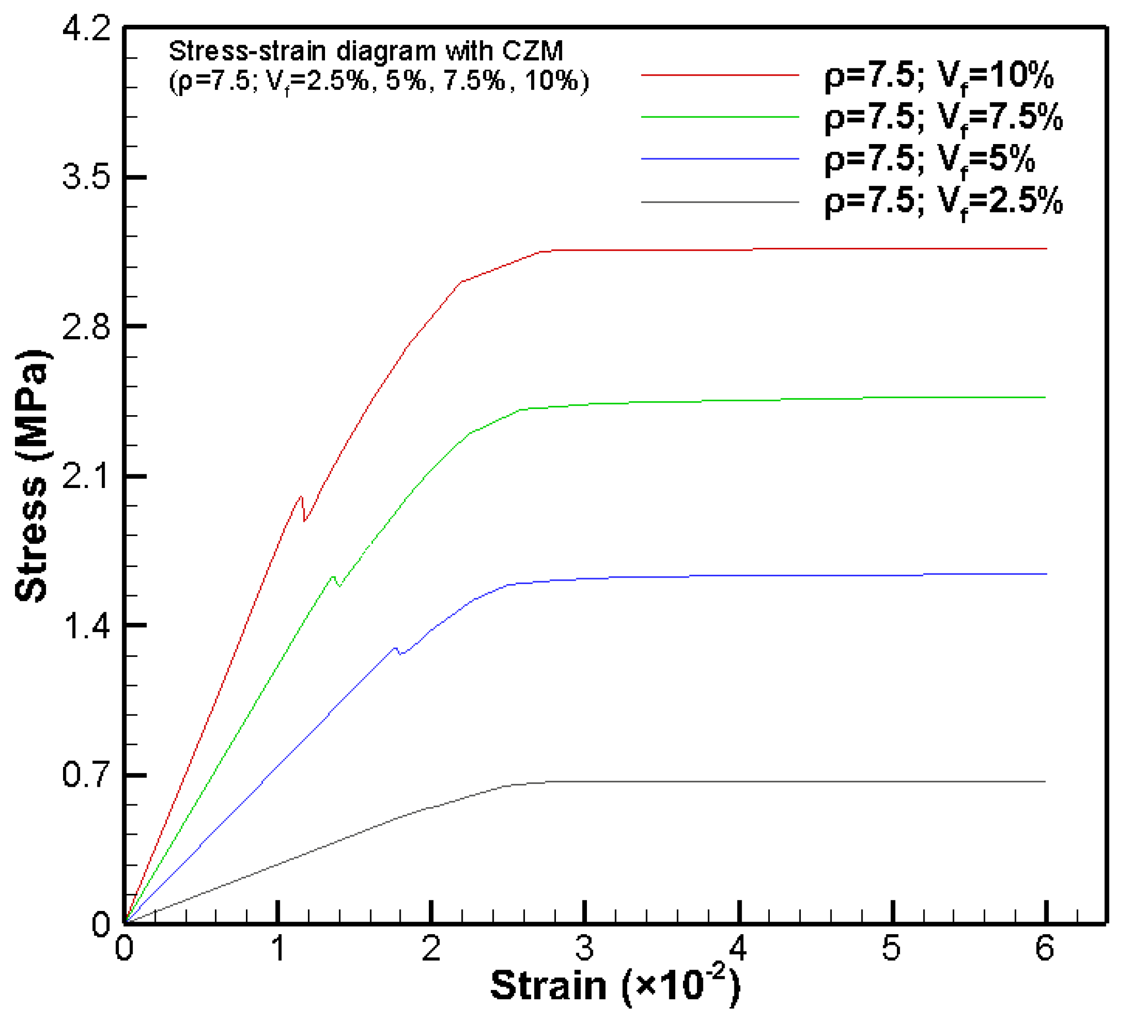
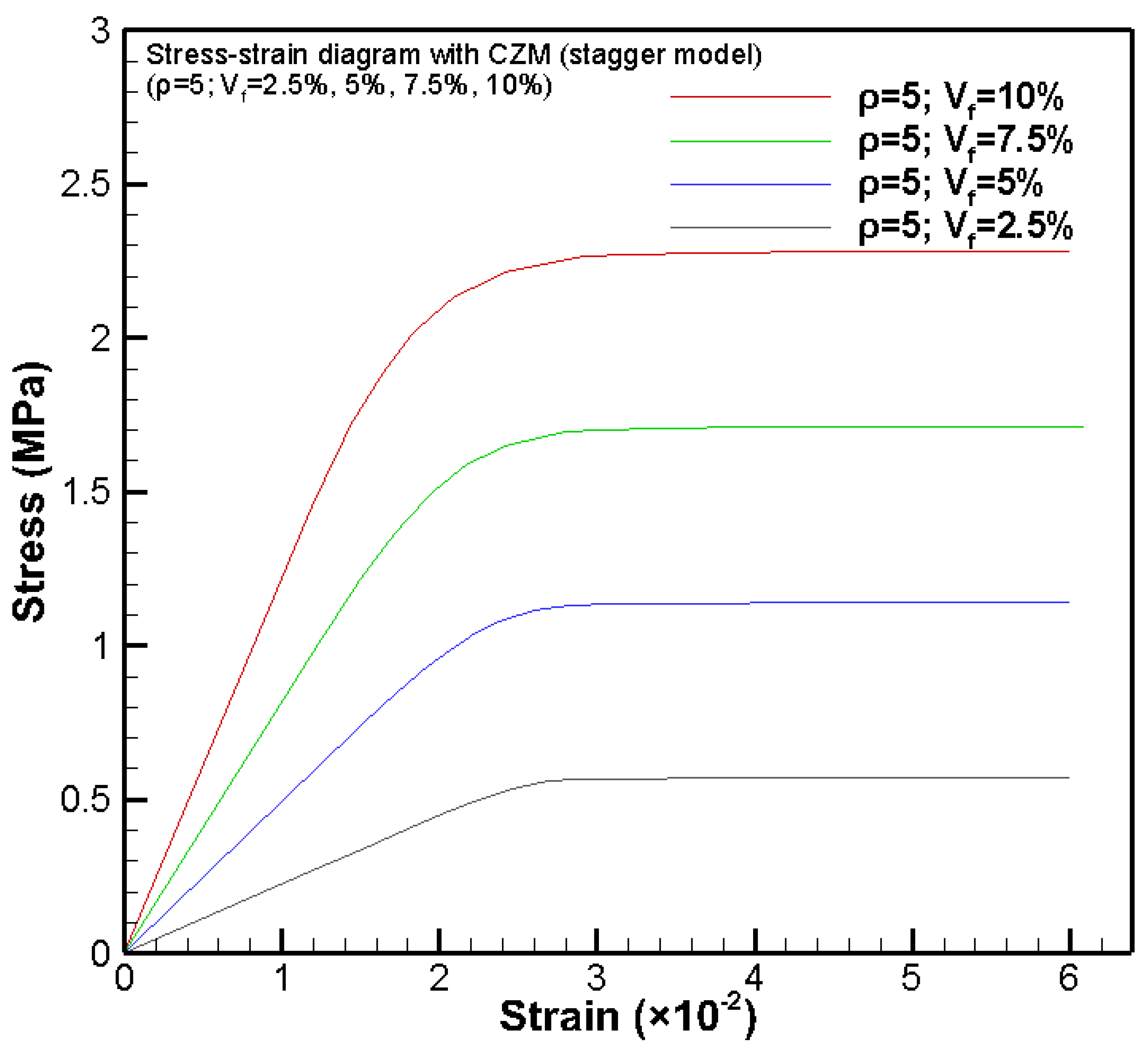
Figure 10, Figure 11, Figure 12 and Figure 13 show the reduced effective stress-strain diagrams of the PNCs with varying clay nanoparticle volume fractions (Vf = 2.5, 5, 7.5, and 10) and nanoparticle aspect ratios (ρ = 5, 7.5, 10 and 20) by FEA integrated with CZM based on the stack clay nanoparticle configuration. In each effective stress-strain diagram, there is a numerically fictitious stress drop in the linearly loading range due to debonding initiation-induced material softening. Such stress dropping phenomenon is decaying with decreasing Vf, and nearly no stress dropping is observable at Vf = 2.5%. For the purpose of comparison, Figure 14 also shows the effective stress-strain diagrams for ρ = 5 and Vf = 2.5, 5, 7.5, and 10 by FEA integrated with CZM based on the stagger clay nanoparticle configuration (Figure 6). It can be found from Figure 10 and Figure 14 that the simulations based on the stagger clay nanoparticle configuration demonstrate no stress dropping and slightly large effective tensile strength. Such observation is due to the fact that the stagger clay nanoparticle configuration designates more evenly distributed clay nanoparticles in the polymeric matrix, corresponding to a higher load-carrying capacity, i.e., a higher effective tensile strength of the PNC [9,10]. In addition, the more evenly distributed stress state in the RVE with a stagger clay nanoparticle configuration suppresses the unable debonding of the nanoparticles, and thus no obvious stress dropping is observed in Figure 14.
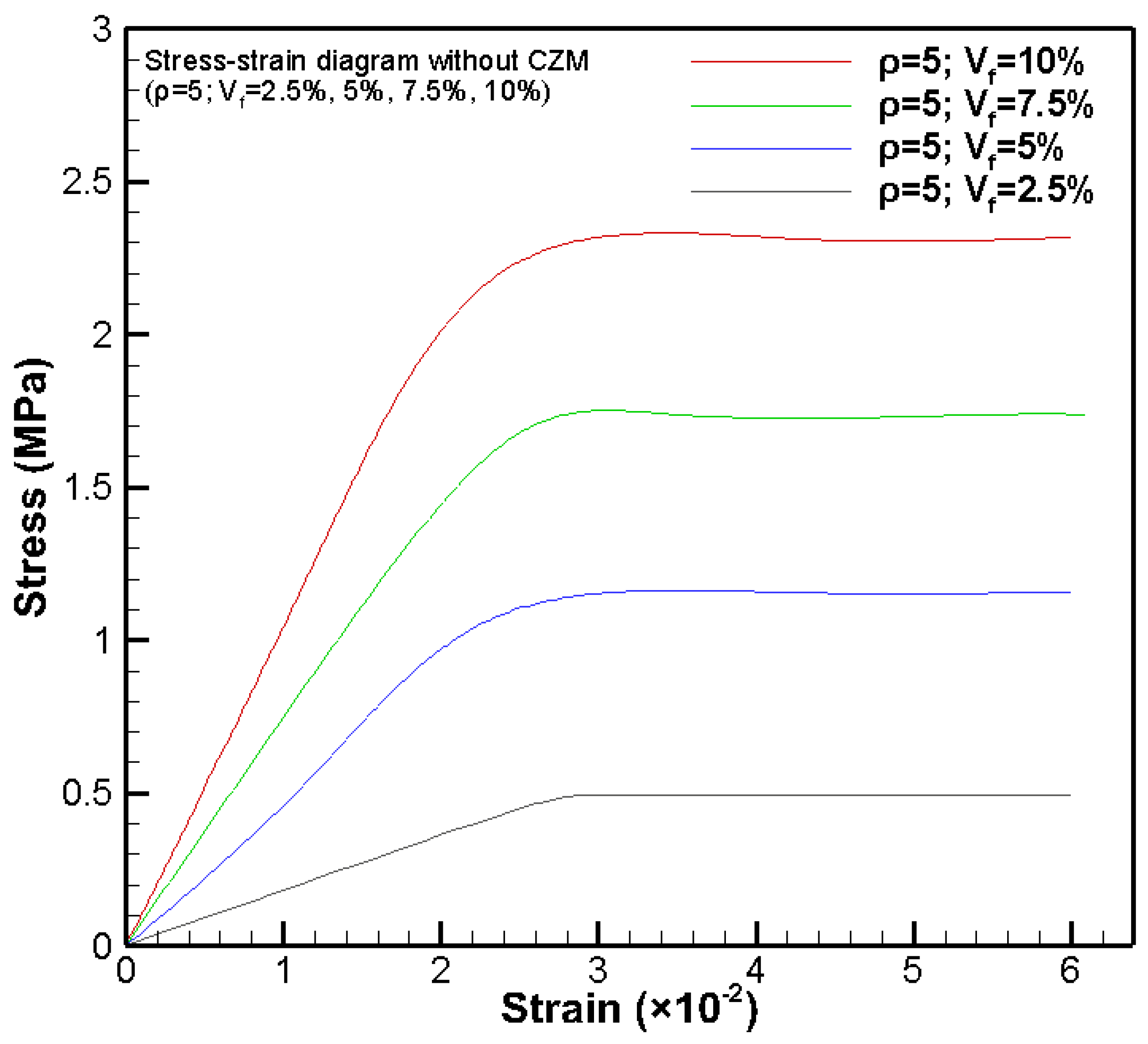
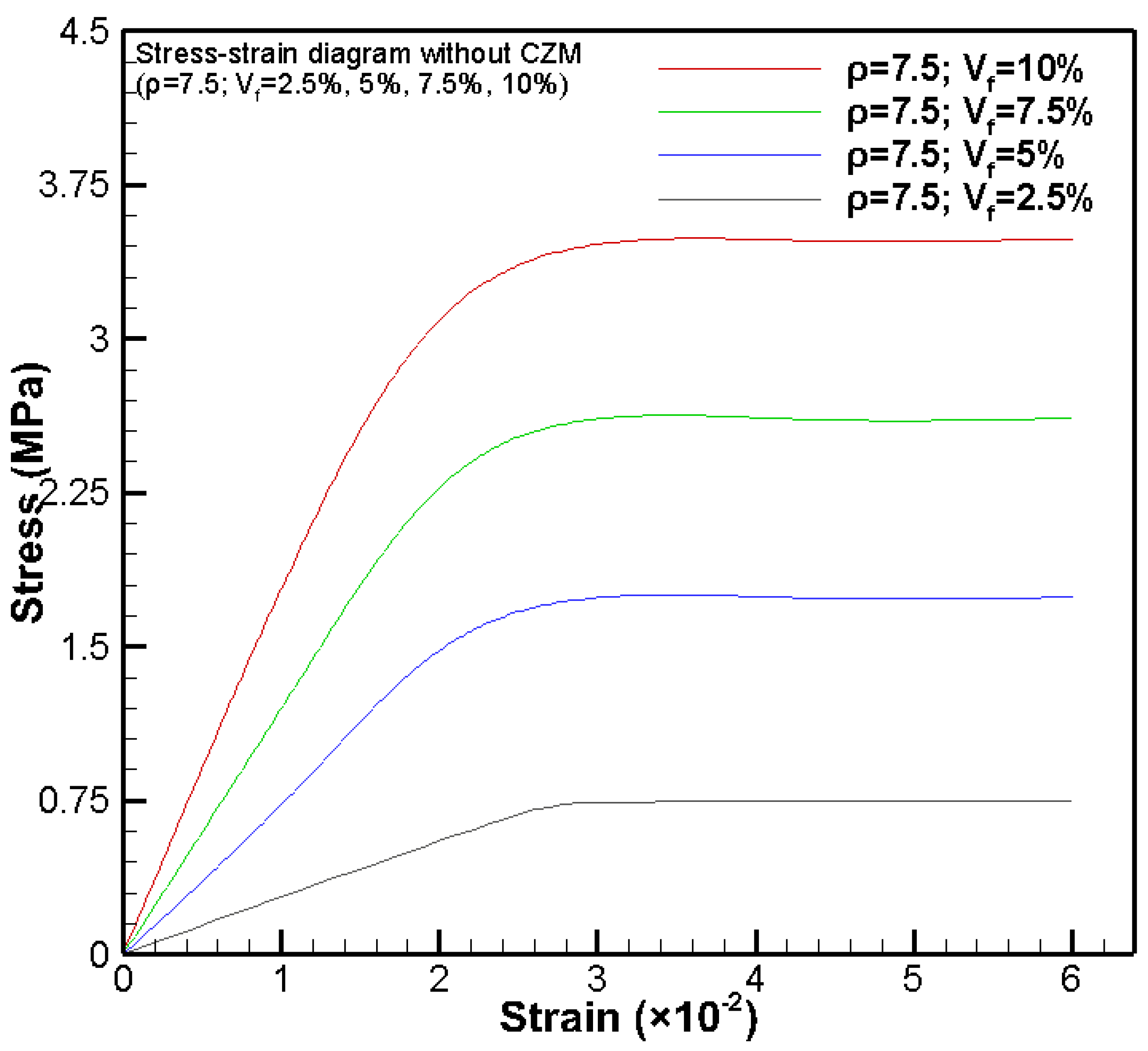
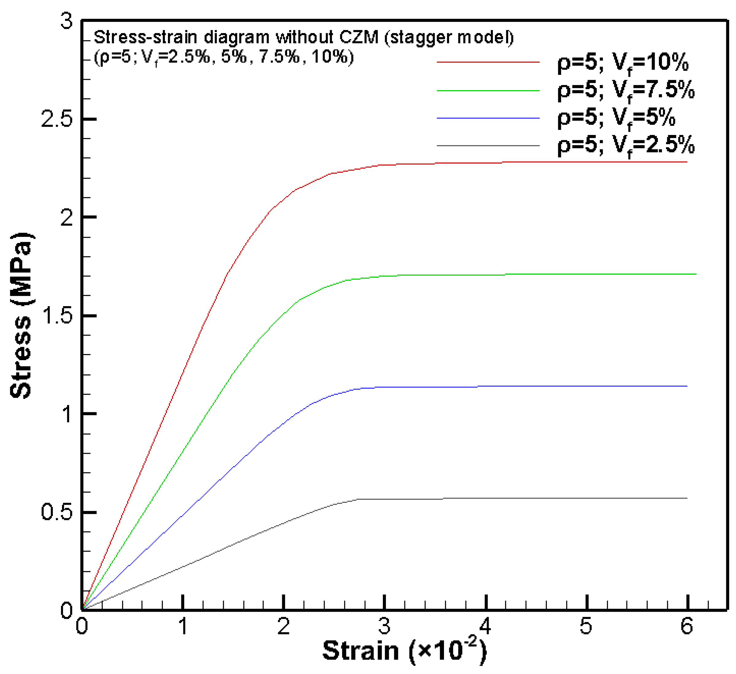
Figure 15, Figure 16, Figure 17 and Figure 18 show the reduced effective stress-strain diagrams of the PNCs with varying clay nanoparticle volume fractions (Vf = 2.5, 5, 7.5, and 10) and aspect ratios (ρ = 5, 7.5, 10 and 20) by FEA without CZM based on the stack clay nanoparticle configuration. In this case, the numerical simulations are purely conventional nonlinear FEA without taking into account debonding induced failure. Once the polymeric resin reaches its yield strength, the PNC reaches its effective ultimate tensile strength, i.e., the yielding of the polymeric resin governs the effective ultimate tensile strength of the PNC [9,10]. Therefore, the shapes of the effective stress-strain diagrams are close to those of idealized elastoplastic materials. For the purpose of comparison, Figure 19 also shows the effective stress-strain diagrams of the PNCs at ρ = 5 and Vf = 2.5, 5, 7.5, and 10 by FEA without CZM based on the stagger clay nanoparticle configuration. It can be found from Figure 15 and Figure 19 that the two cases of nanoparticle distribution configurations predict very close results though the stack clay nanoparticle configuration demonstrates a slightly higher stress state due to its less symmetric configuration compared to that of the stagger clay nanoparticle configuration.
Figure 20 shows the typical von Mises stress and displacement fields of the REV in the progressive debonding process of the edge-curved clay nanoparticle under uniaxial tensile loading along the clay nanoparticle direction by using FEA integrated with CZM, in which the stack clay nanoparticle configuration is evoked. Compared to Figure 7 based on a rectangle-shaped clay nanoparticle, the peak von Mises stress decreases ~12% due to adoption of the curved edges. Such a stress decrease is obvious as the result of eliminating the stress singularity in the RVE reinforced with edge-curved clay nanoparticles.
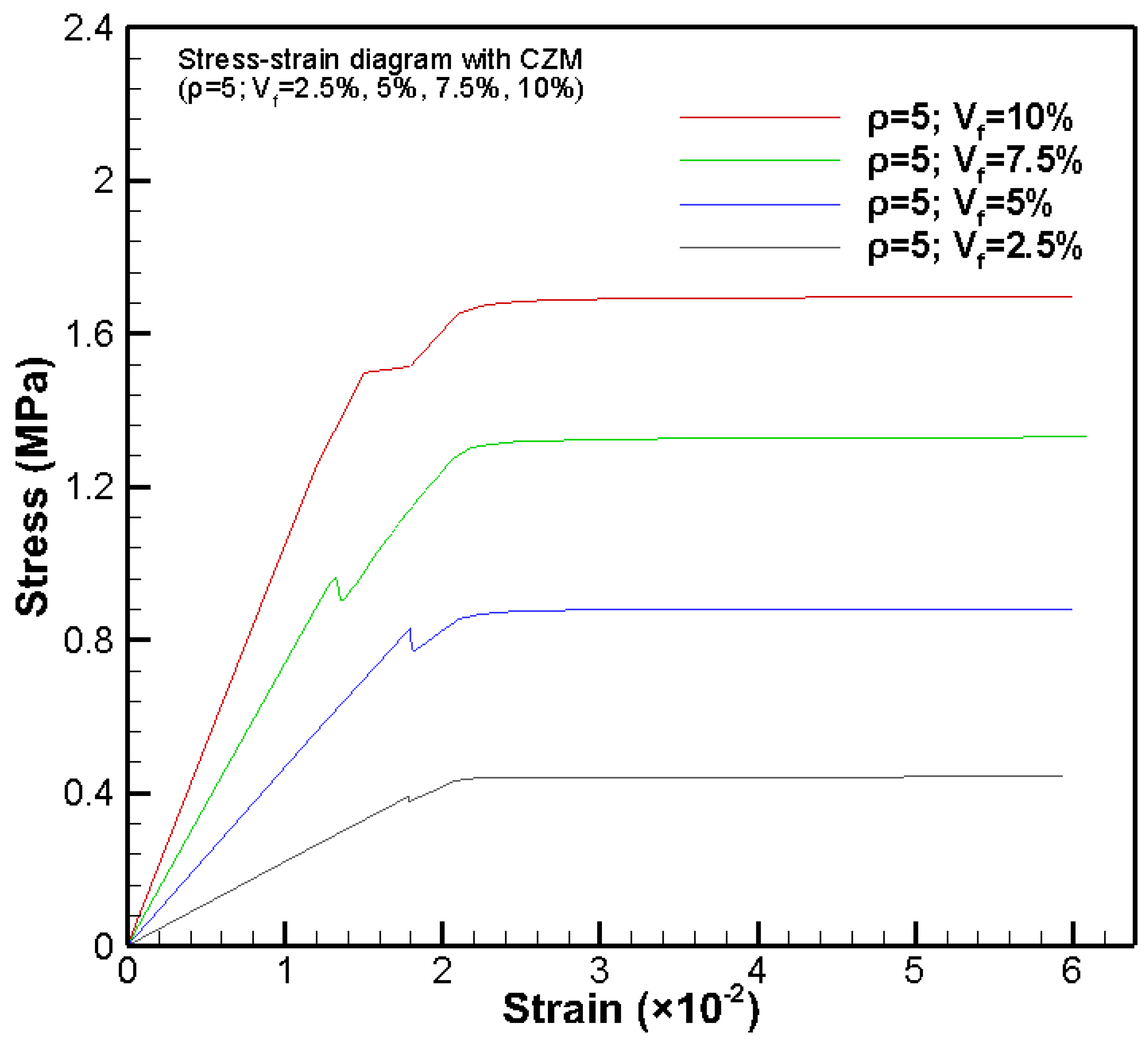
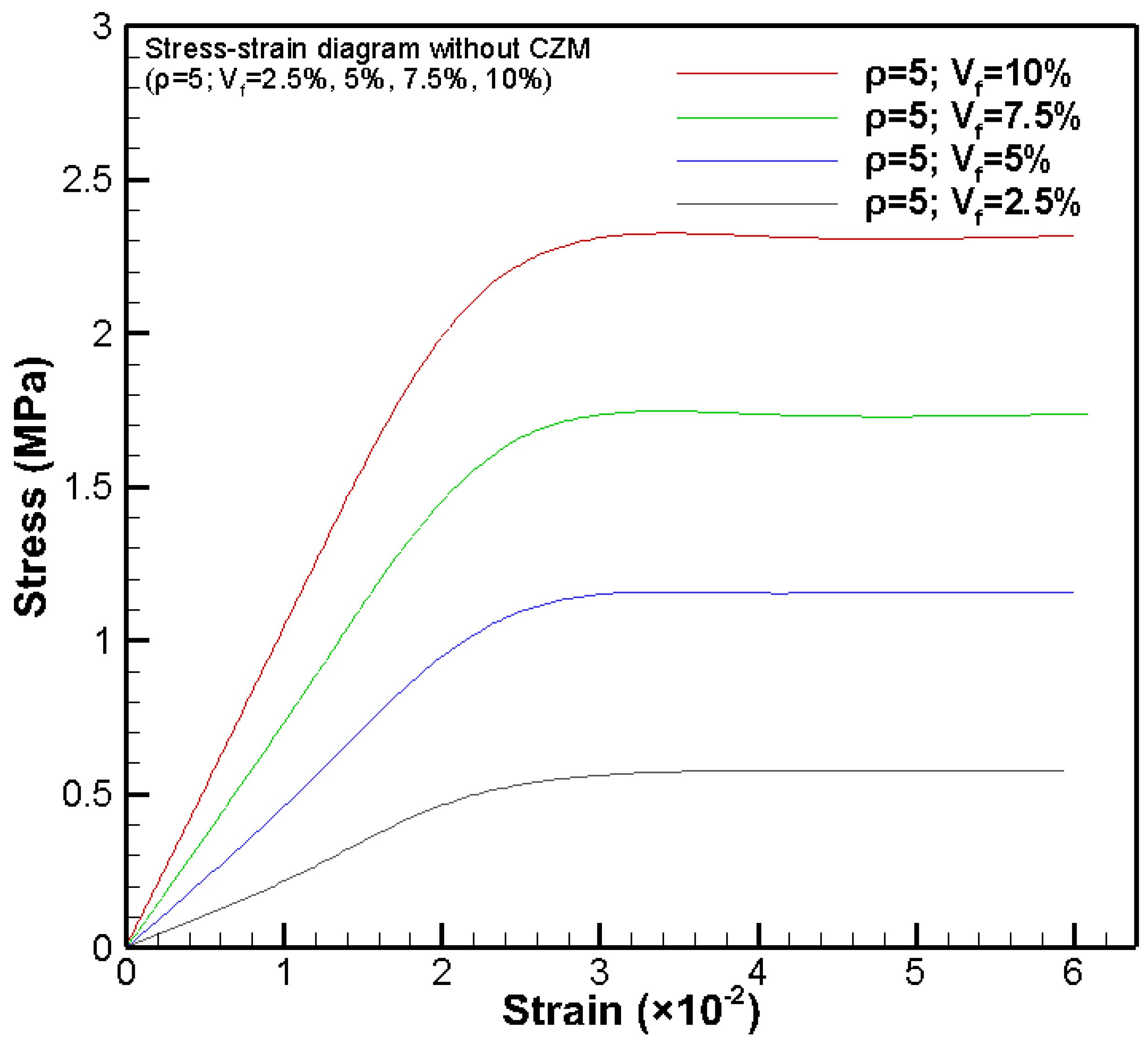
Figure 21 and Figure 22 show the effective stress-strain diagrams of the PNCs of ρ = 5 and Vf = 2.5, 5, 7.5, and 10 by FEA integrated with and without CZM, respectively, based on the stack edge-curved clay nanoparticle configuration. It can be found from Figure 21 that obvious stress dropping exists in the effective stress-strain diagrams for the simulations by FEA integrated with CZM, while no obvious stress dropping is detected for those simulations by using FEA without integration of CZM (Figure 22). In addition, the stress level predicted by FEA integrated with CZM (Figure 21) is larger than that without integration of CZM (Figure 22). In this case, debonding predicted by FEA integrated with CZM (Figure 21) induces a larger stress level at the crack tip than that at the same location of perfectly bonded edge-curved clay nanoparticle in the polymeric resin (Figure 22).

4. Conclusions

The cohesive zone model (CZM) has been integrated into FEM to successfully simulate the entire effective uniaxial stress-strain diagrams of PNCs in a large range of clay nanoparticle volume fraction and aspect ratio. During the numerical process of each case of the clay nanoparticle volume fraction and aspect ratio, two configurations of aligned clay nanoparticle distribution, i.e., the stack and stagger nanoparticle configurations, have been taken into account to approach two idealized clay particle distribution states. Detailed effective uniaxial stress-strain diagrams of the PNCs have been obtained and compared to successfully explore the effects of PNC processing parameters (i.e., the nanoclay volume fraction, aspect ratio, and alignment). It has been shown that increasing either clay nanoparticle volume fraction, aspect ratio, or alignment is the feasible technical approach to achieve high load-carrying capacity, including the effective stiffness and strength of the PNCs. The present CZM-based FEA is capable of predicting the progressive debonding process of the clay nanoparticles in polymer resins under uniaxial tension, which is closer to the realistic failure process of PNCs. Therefore, the present CZM-based FEA can be used to design and optimize the mechanical properties of PNCs. Moreover, the present computational approach can be furthered to include additional material and microstructural properties of PNCs, e.g., nanosized clay-resin interface features, clay particle waviness, three-dimensional geometries, etc. The present CZM-based FEA provides a feasible while effective computational tool for the efficient computer-aided nanocomposite design for targeted mechanical and physical properties and manufacturing.

Author Contributions

X.-F.W. conceived and designed the computational study; U.C. conducted all the FEM simulations and figure plotting; U.C. and X.-F.W. analyzed the data and wrote the paper. All authors have read and agreed to the published version of the manuscript.

Funding

This research was supported by the NASA EPSCoR (NASA grant #NNX07AK81A, seed grant: 43500-2490-FAR018640), NDSU Development Foundation (grant no.: 43500-2490-FAR0017475), and the Department of Mechanical Engineering at NDSU.

Conflicts of Interest

The authors declare no conflict of interest.

References

  1. Dzenis, A. Structural nanocomposites. Science 1998, 319, 419–420. [Google Scholar] [CrossRef]
  2. Wu, X.F.; Yarin, A.L. Recent progress in interfacial toughening and damage self-healing of polymer composites based on electrospun and solution-blown nanofibers. J. Appl. Polym. Sci. 2013, 130, 2225–2237. [Google Scholar] [CrossRef]
  3. Chen, Q.; Zhang, L.; Yoon, M.K.; Wu, X.F.; Arefin, R.H.; Fong, H. Preparation and evaluation of nano-epoxy composite resins containing electrospun glass nanofibers. J. Appl. Polym. Sci. 2012, 124, 444–451. [Google Scholar] [CrossRef]
  4. Wu, X.F.; Rahman, A.; Zhou, Z.; Pelot, D.D.; Sinha-Ray, S.; Chen, B.; Payne, S.; Yarin, A.L. Electrospinning core-shell nanofibers for interfacial toughening and self-healing of carbon-fiber/epoxy composites. J. Appl. Polym. Sci. 2013, 129, 1383–1393. [Google Scholar] [CrossRef]
  5. Wu, X.F.; Zholobko, O.; Zhou, Z.; Rahman, A. Electrospun nanofibers for interfacial toughening and damage self-healing of polymer composites and surface coatings. In Electrospun Polymers and Composites: Ultrafine Materials, High Performance Fibers and Wearables; Woodhead Publishing: Oxford, UK, 2020. [Google Scholar]
  6. Usuki, A.; Kojima, Y.; Kawasumi, M.; Okada, A.; Fukushima, Y.; Kurauchi, T.; Kamigaito, O. Synthesis of nylon 6-clay hybrid. J. Mater. Res. 1993, 8, 1179–1184. [Google Scholar] [CrossRef]
  7. Chan, M.; Lau, K.; Wong, T.; Ho, M.; Hui, D. Mechanism of reinforcement in a nanoclay/polymer composite. Composites B Eng. 2011, 42, 1708–1712. [Google Scholar] [CrossRef]
  8. Almansoori, A.; Majewski, C.; Rodenburg, C. Nanoclay/polymer composite powders for use in laser sintering applications: Effects of nanoclay plasma treatment. J. Mater. 2017, 69, 2278–2285. [Google Scholar] [CrossRef] [PubMed] [Green Version]
  9. Rahman, A.; Wu, X.F. Computational study of the effects of processing parameters on the nonlinear elastoplastic behavior of polymer nanoclay composites. J. Compos. Sci. 2017, 1, 16. [Google Scholar] [CrossRef] [Green Version]
  10. Rahman, A. Fabrication and Mechanical Characterization of Novel Hybrid Carbon-fiber/Epoxy Composites Reinforced with Toughening/Self-Repairing Nanofibers at Interfaces. Ph.D. Thesis, North Dakota State University, Fargo, ND, USA, 2012. [Google Scholar]
  11. Kojima, Y.; Usuki, A.; Kawasumi, M.; Okada, A.; Kurauchi, T.; Kamigaito, O. Synthesis of nylon 6–clay hybrid by montmorillonite intercalated with ϵ-caprolactam. J. Polym. Sci. A Polym. Chem. 1993, 31, 983–986. [Google Scholar] [CrossRef]
  12. Alexandre, M.; Dubois, P. Polymer-layered silicate nanocomposites: Preparation, properties and uses of a new class of materials. Mater. Sci. Eng. R Rep. 2000, 28, 1–63. [Google Scholar] [CrossRef]
  13. Chen, Y.; Chen, H.; Shi, J. In vivo bio-safety evaluations and diagnostic/therapeutic applications of chemically designed mesoporous silica nanoparticles. Adv. Mater. 2013, 25, 3144–3176. [Google Scholar] [CrossRef]
  14. Tjong, S.C. Structural and mechanical properties of polymer nanocomposites. Mater. Sci. Eng. R Rep. 2006, 53, 73–197. [Google Scholar] [CrossRef]
  15. Schadler, L.; Brinson, L.; Sawyer, W. Polymer nanocomposites: A small part of the story. J. Mater. 2007, 59, 53–60. [Google Scholar] [CrossRef]
  16. Paul, D.R.; Robeson, L.M. Polymer nanotechnology: Nanocomposites. Polymer 2008, 49, 3187–3204. [Google Scholar] [CrossRef] [Green Version]
  17. Tucker, C.L., III.; Liang, E. Stiffness predictions for unidirectional short-fiber composites: Review and evaluation. Compos. Sci. Technol. 1999, 59, 655–671. [Google Scholar] [CrossRef]
  18. Weon, J.I.; Sue, H.J. Effects of clay orientation and aspect ratio on mechanical behavior of nylon-6 nanocomposite. Polymer 2005, 46, 6325–6334. [Google Scholar] [CrossRef]
  19. Tsai, J.; Sun, C. Effect of platelet dispersion on the load transfer efficiency in nanoclay composites. J. Compos. Mater. 2004, 38, 567–579. [Google Scholar] [CrossRef]
  20. Dong, Y.; Bhattacharyya, D. A simple micromechanical approach to predict mechanical behaviour of polypropylene/organoclay nanocomposites based on representative volume element (RVE). Comput. Mater. Sci. 2010, 49, 1–8. [Google Scholar] [CrossRef]
  21. Hu, H.; Onyebueke, L.; Abatan, A. Characterizing and modeling mechanical properties of nanocomposites-review and evaluation. J. Miner. Mater. Character. Eng. 2010, 9, 275–319. [Google Scholar] [CrossRef]
  22. Barenblatt, G.I. The formation of equilibrium cracks during brittle fracture: General ideas and hypotheses, axially symmetric cracks. Appl. Math. Mech. 1959, 23, 622–636. [Google Scholar] [CrossRef]
  23. Barenblatt, G.I. The mathematical theory of equilibrium in brittle fracture. Adv. Appl. Mech. 1962, 7, 55–129. [Google Scholar]
  24. Dugdale, D.S. Yielding of steel sheets containing slits. J. Mech. Phys. Solids 1960, 8, 100–104. [Google Scholar] [CrossRef]
  25. Park, K.; Paulino, G.H. Cohesive zone models: A critical review of traction-separation relationships across fracture surfaces. Appl. Mech. Rev. 2011, 64, 060802. [Google Scholar] [CrossRef]
  26. ANSYS® Theory Reference (Version 16); ANSYS, Inc.: Canonsburg, PA, USA, 2016.
  27. Wu, X.F.; Chowdhury, U. Computational analysis of the mechanical strength and debonding process of adhesively bonded joints. Int. J. Solid Mater. 2019, 1, 171–225. [Google Scholar]
  28. Chowdhury, U. Theoretical and Computational Studies of the Strength and Fracture Toughness of Adhesively Bonded Joints and Polymer Nanoclay Composites. Ph.D. Thesis, North Dakota State University, Fargo, ND, USA, 2018. [Google Scholar]
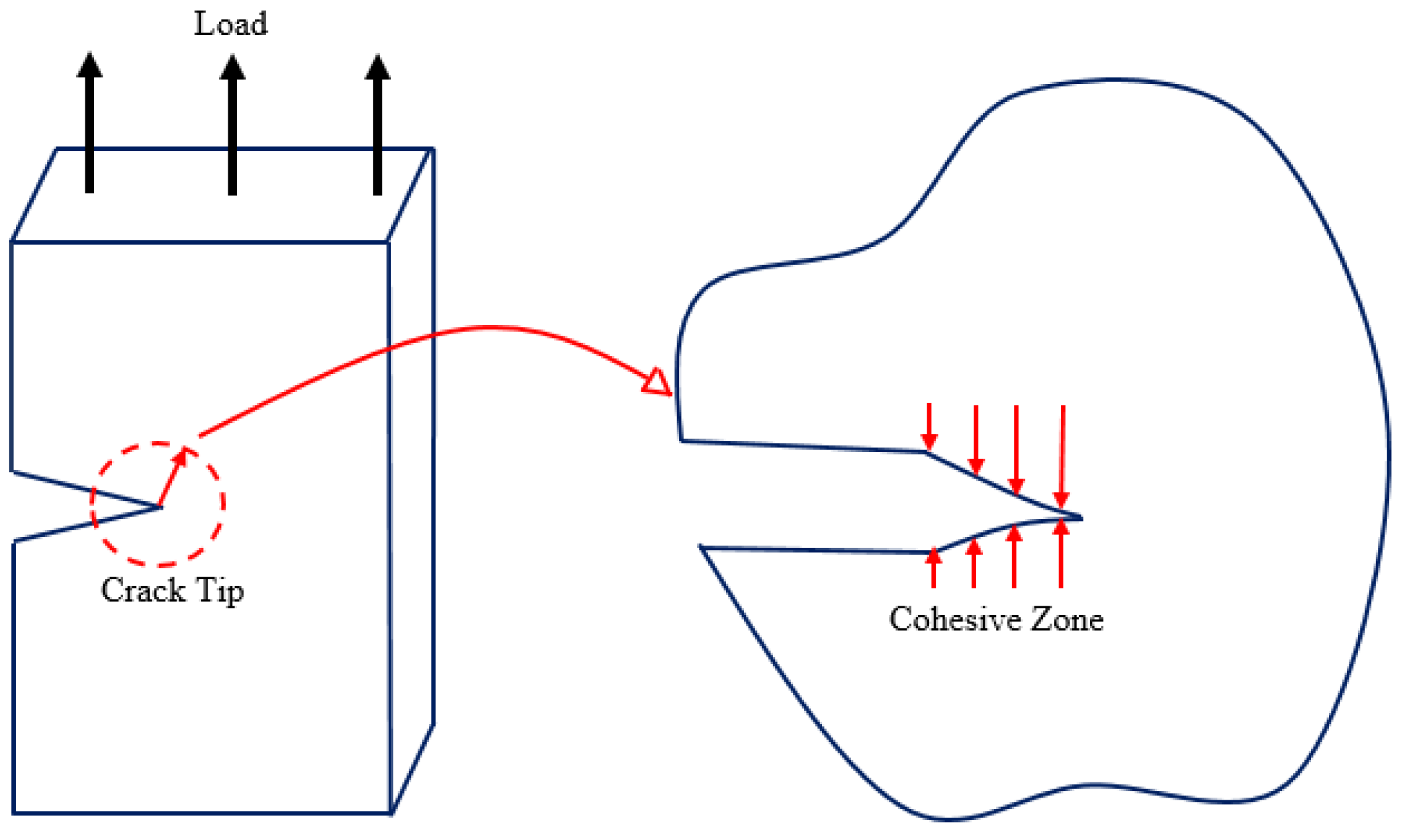
Figure 1. Schematic cohesive zone model.
Jcs 05 00131 g001
Figure 2. Typical cohesive zone models.
Jcs 05 00131 g002
Figure 3. (a) Schematic node normal and tangential stresses and displacements in CZM- based FEM modeling of the debonding process of clay nanoparticles in PNCs. (b) Schematic σnn and σtt relations of a bilinear CZM.
Jcs 05 00131 g003
Figure 4. Schematic of a polymer nanoclay composite (PNC) reinforced with randomly distributed intercalated and fully exfoliated clay particles.
Jcs 05 00131 g004
Figure 5. Representative volume element (RVE) of a PNC reinforced with aligned, identical clay nanoparticles in a stack distribution configuration. (a) Idealized identical stacking clay platelets; (b) a typical RVE; and (c) a quarter RVE for efficient simulation.
Jcs 05 00131 g005
Figure 6. Representative volume element (RVE) of a PNC reinforced with aligned, identical clay nanoparticles in a stagger distribution configuration. (a) Idealized identical staggering clay platelets; (b) a typical RVE; and (c) a quarter RVE for efficient simulation.
Jcs 05 00131 g006
Figure 7. von Mises stress and displacement fields of the RVE of a PNC reinforced with a rectangle-shaped clay nanoparticle: (a) crack initiates, (b) crack propagates, and (c) crack propagates at the final failure.
Jcs 05 00131 g007
Figure 8. Variations of the effective ultimate tensile strength σult with the clay nanoparticle volume fraction Vf at the aspect ratio of ρ = 5, 7.5, 10, and 20, respectively.
Jcs 05 00131 g008
Figure 9. Variations of the effective elastic modulus Ee with the clay nanoparticle volume fraction Vf at the aspect ratio of ρ = 5, 7.5, 10, and 20, respectively.
Jcs 05 00131 g009
Figure 10. Effective stress-strain diagrams of the PNC (stack nanoparticle configuration) with CZM at the nanoparticle volume fraction of Vf = 2.5%, 5%, 7.5% and 10%, respectively (ρ = 5).
Jcs 05 00131 g010
Figure 11. Effective stress-strain diagrams of the PNC (stack model) with CZM at the nanoparticle volume fraction of Vf = 2.5%, 5%, 7.5%, and 10%, respectively (ρ = 7.5).
Jcs 05 00131 g011
Figure 12. Effective stress-strain diagrams of the PNC (stack nanoparticle configuration) with CZM at the nanoparticle volume fraction of Vf = 2.5%, 5%, 7.5%, and 10%, respectively (ρ = 10).
Jcs 05 00131 g012
Figure 13. Effective stress-strain diagrams of the PNC (stack nanoparticle configuration) with CZM at the nanoparticle volume fraction of Vf = 2.5%, 5%, 7.5%, and 10%, respectively (ρ = 20).
Jcs 05 00131 g013
Figure 14. Effective stress-strain diagrams of the PNC (stagger nanoparticle configuration) with CZM at the nanoparticle volume fractions Vf = 2.5%, 5%, 7.5%, and 10% at the clay particle aspect ratio ρ = 5.
Jcs 05 00131 g014
Figure 15. Effective stress-strain diagrams of the PNC (stack nanoparticle configuration) without CZM at the nanoparticle volume fraction of Vf = 2.5%, 5%, 7.5%, and 10%, respectively (ρ = 5).
Jcs 05 00131 g015
Figure 16. Effective stress-strain diagrams of the PNC (stack nanoparticle configuration) without CZM at the nanoparticle volume fraction of Vf = 2.5%, 5%, 7.5%, and 10%, respectively (ρ = 7.5).
Jcs 05 00131 g016
Figure 17. Effective stress-strain diagrams of the PNC (stack nanoparticle configuration) without CZM at the nanoparticle volume fraction of Vf = 2.5%, 5%, 7.5%, and 10%, respectively (ρ = 10).
Jcs 05 00131 g017
Figure 18. Effective stress-strain diagrams of the PNC (stack nanoparticle configuration) without CZM at the nanoparticle volume fraction of Vf = 2.5%, 5%, 7.5%, and 10%, respectively (ρ = 20).
Jcs 05 00131 g018
Figure 19. Effective stress-strain diagrams of the PNC (stagger nanoparticle configuration) without CZM at the nanoparticle volume fraction of Vf = 2.5%, 5%, 7.5%, and 10%, respectively (ρ = 5).
Jcs 05 00131 g019
Figure 20. von Mises stress and displacement fields of the RVE of a PNC reinforced with an edge-curved clay nanoparticle: (a) crack initiates, (b) crack propagates, and (c) crack propagates to the final failure.
Jcs 05 00131 g020
Figure 21. Effective stress-strain diagrams of the PNC (reinforced with edge-curved clay nanoparticles) with CZM at the nanoparticle volume fraction of Vf = 2.5%, 5%, 7.5%, and 10%, respectively (ρ = 5).
Jcs 05 00131 g021
Figure 22. Effective stress-strain diagrams of the PNC (reinforced with edge-curved clay nanoparticles) without CZM at the nanoparticle volume fraction of Vf = 2.5%, 5%, 7.5%, and 10%, respectively (ρ = 5).
Jcs 05 00131 g022
Publisher’s Note: MDPI stays neutral with regard to jurisdictional claims in published maps and institutional affiliations.