Article

Effects of Water Absorption on the Fiber–Matrix Interfacial Shear Strength of Carbon Nanotube-Grafted Carbon Fiber Reinforced Polyamide Resin

Department of Biomedical Engineering, Doshisha University, Kyoto 610-0321, Japan
*
Author to whom correspondence should be addressed.
J. Compos. Sci. 2019, 3(1), 4; https://doi.org/10.3390/jcs3010004
Submission received: 23 November 2018 / Revised: 28 December 2018 / Accepted: 4 January 2019 / Published: 7 January 2019

Abstract

:
Carbon fiber reinforced thermoplastics (CFRTPs) are expected to be used for the structural parts of automobiles and aircraft due to their mechanical properties, such as high specific stiffness, high specific strength, short molding times and high recyclability. The fiber/matrix interface of the composite plays an important role in transmitting stress from the matrix to the reinforcing fibers. It was reported that grafting of carbon nanotubes (CNTs) on the carbon fiber can improve the fiber/matrix interfacial property. We have reported that CNTs, which are directly grafted onto carbon fiber using Ni as the catalyst by the chemical vapor deposition (CVD) method, can improve the fiber/matrix interfacial shear strength (IFSS) of carbon fiber/polyamide 6 (PA6). For practical use of CFRTPs, it is important to clarify the effects of water absorption on the mechanical properties of the composite material. In this study, the effects of water absorption on the fiber–matrix interfacial shear strength (IFSS) of carbon fiber reinforced polyamide resin and CNT-grafted carbon fiber reinforced polyamide resin were clarified by the single fiber pull-out test for specimens preserved in air, then in water for 24 h and re-dried after water absorption. The IFSS of carbon fiber/PA6 was significantly decreased by water absorption. In contrast, CNT-grafted carbon fiber/PA6 showed smaller degradation of the IFSS by water absorption.

1. Introduction

Carbon fiber reinforced thermoplastics (CFRTPs) are expected to be used for the structural parts of automobiles and aircraft due to their mechanical properties, such as light weight, high specific stiffness, high specific strength, short molding times and high recyclability [1,2,3,4,5]. The mechanical behavior of composites depends not only on the properties of the reinforcing fibers and the matrix, but also on the characteristics of the interface between the fiber and the matrix [6,7], as the fiber–matrix interface is responsible for stress transfer from the matrix to the reinforcing fibers. It is necessary to control their interfacial properties. For this purpose, the surface modification of carbon fibers [8,9,10] has been conducted for many years.
Carbon nanotubes (CNTs) are graphene sheets in the shape of a tube whose diameter is on the nanometer order. With their small size and remarkable mechanical, electrical and thermal properties, CNTs have been considered promising materials to be used in advanced composites [11]. CNTs are generally produced by carbon-arc discharge, laser ablation, and chemical vapor deposition (CVD). Among them, CVD has the specific characteristic to graft CNTs directly onto carbon fibers [11,12,13].
On the other hand, grafting CNTs using the CVD method sometimes weakens the strength of the carbon fibers. In previous studies, CNTs were grafted onto carbon fibers at over 700 °C and the tensile strength of CNT-grafted carbon fiber was decreased due to degradation by oxidation [14,15,16]. It is reported that CNTs were grafted onto a copper plate at a low temperature of 500 °C by an alcohol CVD method using Ni for the metal catalyst and ethanol for the carbon source [17]. We developed CNT grafting methods using Ni as a catalyst for CNT-deposition and ethanol as a gas at a relatively lower temperature of 600 °C or less [18]. We reported that the grafting of carbon CNTs onto carbon fibers can improve the fiber–matrix interfacial shear strength (IFSS) with thermoplastics due to the increase of the surface area and mechanical interlocking by CNTs [18].
It was also reported that the fiber–matrix interfacial shear strength with thermoset plastic was improved by grafting CNT onto carbon fiber [19] and the mechanical properties of CFRP using CNT-grafted CF were improved [20].
Polyamide has an expected use in the automobile industry since it has an affordable price with high mechanical properties and can be molded at a relatively low temperature of 230 °C; however, it has a disadvantage in that it absorbs water [21,22]. Considering the service condition of CFRTPs, such as on a rainy day, it is necessary to evaluate the effects of water absorption on their mechanical properties. We have reported that the fiber–matrix interfacial shear strength, measured by single fiber pull-out tests using a model composite of carbon fiber reinforced polyamide 6, decreases due to water absorption [23,24]. The effect of water absorption on the strength of CNT-grafted carbon fiber reinforced polyamide resin has yet to be clarified.
In this study, the swelling of the polyamide 6 resin by water absorption at 80 °C for 24 h was measured. Additionally, the effects of water absorption on the fiber–matrix interfacial shear strength of CNT-grafted carbon fiber reinforced polyamide 6 resin were investigated by using single fiber pull-out tests.

2. Materials and Methods

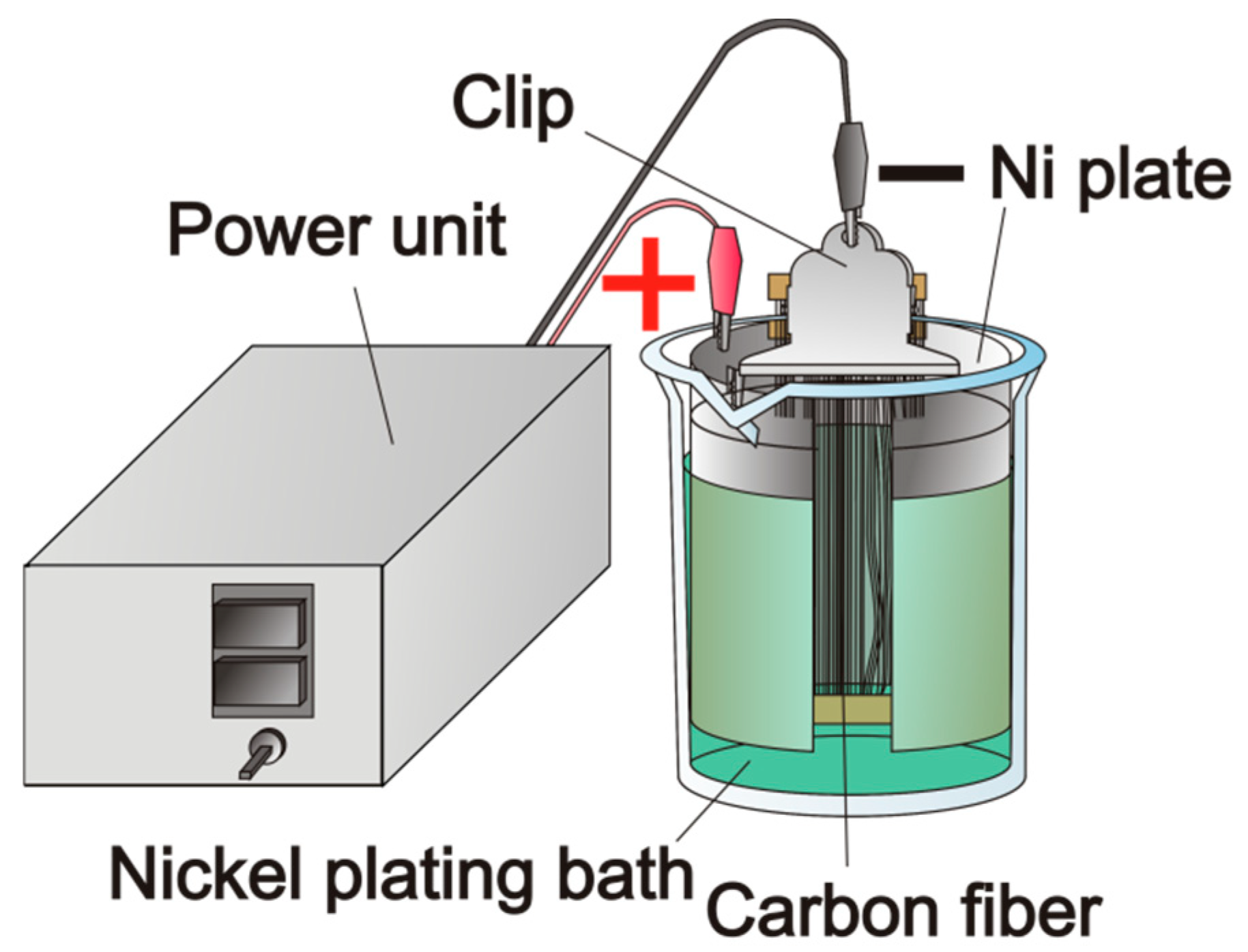
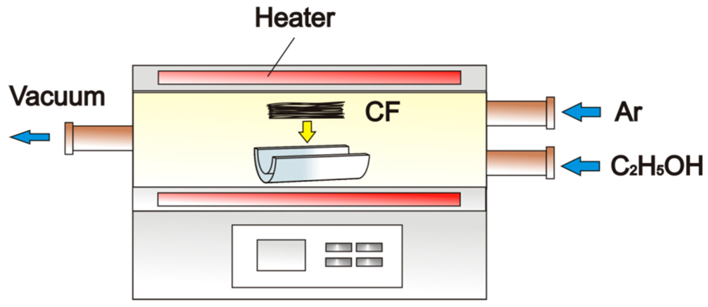
2.1. Materials and Methods of CNT Deposition

Spread PAN-based carbon fibers (Nippon Tokushu Fabric, Katsuyama, Japan), hereafter referred to as As-received-carbon fiber (CF)) and polyamide 6 (PA6, 1015B, Ube Industries, Ltd., Tokyo, Japan), were used for a single fiber pull-out test. Ni particles were plated onto the surface of the carbon fibers as a catalyst metal for CNT grafting by the electrolytic Ni plating method as shown in Figure 1. The components of the plating bath were Nickel sulfate hexahydrate (240 g/L), nickel chloride hexahydrate (45 g/L) and boracic acid (30 g/L). The plating time was set for 15 s and the current density was set for 0.13 mA/mm2. These Ni-plated carbon fibers are referred to as Ni–CF.
CNTs were directly grafted onto the carbon fibers by the CVD system (MPCVD-70, Microphase, Tsukuba, Japan) at 600 °C with a flow of ethanol as the carbon source at a flow rate of 2 mL/min to deposit the CNTs as shown in Figure 2. The flow rate of Ar gas was 200 mL/min, and ethanol gas was injected for 30 min. CNT-grafted carbon fibers are referred to as CNT–CF. These carbon fibers were observed by scanning electron microscope (SEM, JSM-6390LT, JEOL Ltd., Tokyo, Japan) and field emission scanning electron microscope (FE-SEM, JSM-7500FD, JEOL).

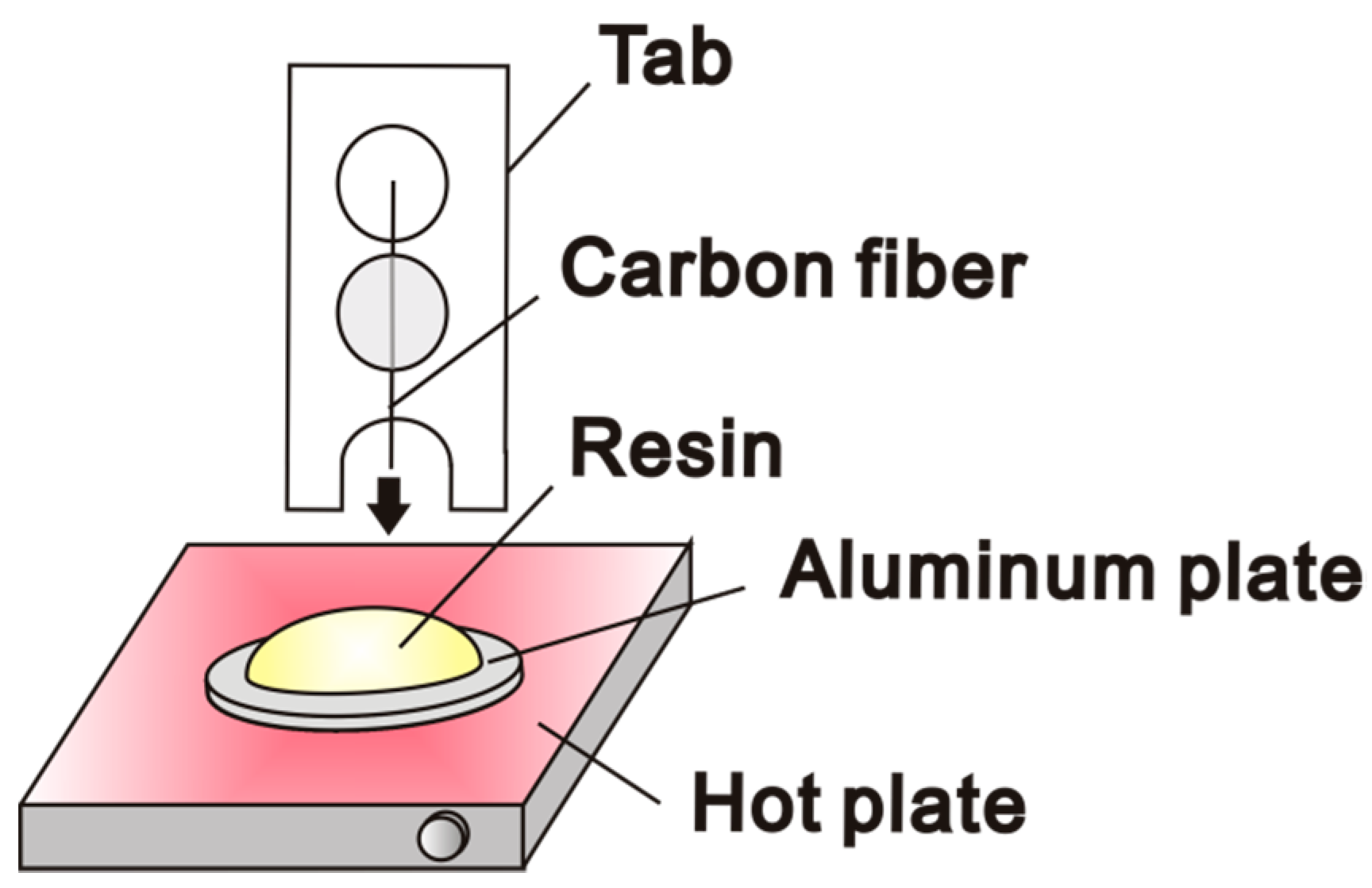
2.2. Single Fiber Pull-Out Test

The fiber–matrix interfacial shear strength (IFSS) of the as-received carbon fiber and the CNT-grafted carbon fiber (CNT–CF) with polyamide 6 was measured by a single fiber pull-out test. Figure 3 shows a schematic drawing of the fabrication of a pull-out test specimen. After a single carbon fiber was glued to a tab, it was then attached to a micromanipulator. Polyamide resin was placed on the aluminum plate and heated to 230 °C. After the single fiber was embedded into the melted resin by operating the micromanipulator, it was then air-cooled. These specimens are referred to as Dry. Some specimens were immersed in pure water at 80 °C for 24 h, and are referred to as Wet. The water absorbed specimens (Wet) that were dried by keeping them in a thermostatic chamber at 80 °C for 24 h are referred to as Redry. Single fiber pull-out tests were conducted by a micro-material testing machine (MMT, MMT-11N, Shimadzu, Kyoto, Japan) with a 2.5 N load cell at a displacement rate of 1.67 × 10⁻⁵/s (1 mm/min) as shown in Figure 4. The diameter of each carbon fiber was measured by SEM after each single fiber pull-out test.
The fiber–matrix interfacial shear strength, τ, was calculated by the following Equation (1):
τ = F max π d l
where F max is the maximum load in the pull-out test, d is the fiber diameter and l is the embedded fiber length.

3. Results and Discussion

3.1. CNT Grafting

Figure 5 shows the surface of Dry-Ni–CF and Dry-CNT–CF. While Ni can be observed on the surface of Dry-Ni–CF, there are some places where Ni does not exist. The sizing agent, which has a higher electric resistance than carbon fiber, is considered to cover this area. Therefore, Ni is less likely to be plated on the sizing agent adhering area. CNTs have grown on the surface of the Dry-CNT–CF, as Ni acts as a catalyst.

3.2. Swelling of Polyamide 6 Resin by Water Absorption

Figure 6 shows the length change of polyamide 6 by water absorption. The length of the polyamide 6 increased by 2.4% after it was immersed in pure water at 80 °C for 24 h. After the polyamide 6 was re-dried in a hot chamber at 80 °C for 24 h, the length returned to almost the same length as in its initial condition (0.05%). The length of the actual pull-out test piece is much smaller than the length of the resin measured. Therefore, the re-drying process of 80 °C for 24 h, which was applied to the wet specimens to re-dry, is enough to fully remove the water in Redry specimens.

3.3. Single Fiber Pull-Out Test

Figure 7 shows the fiber–matrix interfacial shear strength obtained by single fiber pull-out tests. We reported that CNT-grafted carbon fiber has higher fiber–matrix interfacial shear strength than As-received carbon fiber [12]. As observed in the previous study, the fiber–matrix interfacial shear strength of Dry-CNT–CF is higher than that of Dry-As-received-CF. Wet-As-received-CF decreased by 51% and Wet-CNT–CF decreased by 18% compared to the dry version. Although the fiber–matrix interfacial shear strengths of Wet-As-received-CF and Wet-CNT–CF decreased due to water absorption, the decrease rate of Wet-CNT–CF is lower than that of the Wet-As-received-CF. The decrease rate due to water absorption was suppressed by CNT grafting on carbon fibers. For both As-received-CF and CNT–CF, the fiber–matrix interfacial shear strength of the Redry specimen is almost the same as the dry specimen. Re-drying can recover the fiber–matrix interfacial shear strength after water absorption.
Figure 8 shows the SEM images of pulled-out carbon fibers. In Dry-As-received-CF, the fiber surface is smooth and resin does not remain on the fiber surface. The fiber surface is similarly smooth in Wet-As-received-CF as well as in Redry-As-received-CF. However, in Wet-CNT–CF, a small amount of resin remains on the fiber surface. Furthermore, resin remains on the fiber surface close to the meniscus in Dry-CNT–CF and Redry-CNT–CF.
The shear strength of polyamide 6 is reported to be about 95% of its tensile strength [25]. The shear strength of polyamide 6 used in this study was not reported. However, considering that the tensile strength of PA6 (1015B) is 71 MPa [26], the shear strength is assumed to be around 67 MPa. The fiber–matrix interfacial shear strength of Dry-CNT–CF is close to the shear strength of the matrix resin of polyamide 6. Due to the high fiber–matrix interfacial shear strength of CNT-grafted carbon fiber reinforced polyamide 6, fracture is considered to occur in the resin instead of the fiber–matrix interface and, therefore, the resin remains on the fiber surface of Dry-CNT–CF.
In our previous study, we conducted single fiber pull-out tests at high temperature using carbon fiber reinforced polyamide resin and analyzed the thermal expansion of polyamide 6 [27]. Figure 9 shows the schematic drawing of residual stress at the fiber–matrix interface, which is decreased by high temperature. During the preparation process of the specimen, resin tightens the fiber due to the thermal shrinkage of the resin. This tightening stress will be the residual stress at the fiber–matrix interface. We have clarified that the expansion of the resin by high temperature in the radially outward direction reduced the residual stress as shown in Figure 9, and decreased the fiber–matrix interfacial shear strength in the pull-out tests [27].
Figure 10 shows a schematic drawing of the residual stress that varied by water absorption and re-drying. Polyamide (PA) 6 expanded with the weight increase by the water absorption as shown in Figure 6, which is similar to the behavior at high temperature. The fiber–matrix interfacial shear strength is considered to decrease after water absorption because of the reduction of residual stress that tightens the fiber in the single fiber pullout test. Corresponding to the behavior of the length change of PA6 by water absorption and re-drying after water absorption as shown in Figure 6, while water absorption decreased the fiber–matrix interfacial shear strength, re-drying recovered the fiber–matrix interfacial shear strength.
Figure 11 shows a schematic drawing of the residual strength affected by CNT grafting. In CNT–CF, even if the residual stress was reduced by water absorption, the bonding between the fiber and the resin is maintained due to the mechanical interlocking by CNTs. Therefore, the decrease rate of the fiber–matrix interfacial shear strength by water absorption in CNT–CF is considered to be lower than that in As-received-CF.

4. Conclusions

In this study, the effects of water absorption on the fiber–matrix interfacial shear strength of carbon fiber reinforced polyamide resin and CNT-grafted carbon fiber reinforced polyamide resin were clarified by the single fiber pull-out test. Specimens were preserved in air, then in water for 24 h and re-dried after water absorption. The investigation yielded the following conclusions.
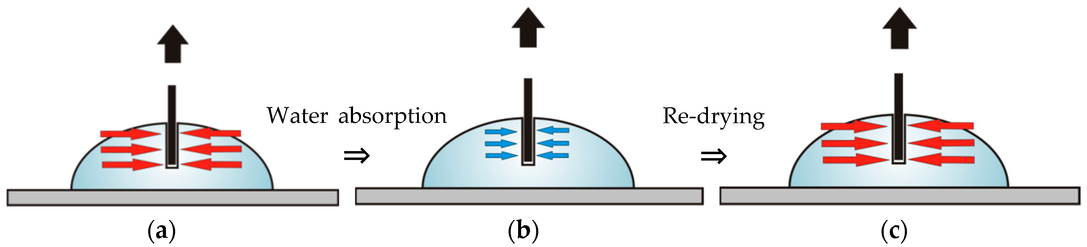
  • The length of polyamide 6 increased by 2.4% after it was immersed in pure water at 80 °C for 24 h. After polyamide 6 was re-dried in a hot chamber at 80 °C for 24 h, the length returned to almost the same length as the initial condition (0.05%). Corresponding to the behavior of the length change of PA6 by water absorption and re-drying, while water absorption decreased the fiber–matrix interfacial shear strength, re-drying recovered it.
  • In CNT–CF, even if the residual stress was reduced by water absorption, the bonding between the fiber and the resin is maintained due to the mechanical interlocking by CNTs. Therefore, the decreased rate of the fiber–matrix interfacial shear strength by water absorption in CNT–CF is lower than that in As-received CF.

Author Contributions

Conceptualization, K.T.; Methodology, K.T.; Investigation, S.O. and Y.H.; Writing-Original Draft Preparation, S.O.; Writing-Review & Editing, K.T.; Supervision, T.K.; Project Administration, K.T.; Funding Acquisition, K.T. and T.K.

Funding

This work was partially supported by KAKENHI (Japan Society for the Promotion of Science, Grant-in-Aid for Scientific Research (B))(26289011) and a research project on “Research and Development Center for Advanced Composite Materials” of Doshisha University and MEXT (the Ministry of Education, Culture, Sports, Science and Technology, Japan)—Supported Program for the Strategic Research Foundation at Private Universities, 2013-2017, the project S1311036.

Conflicts of Interest

The authors declare no conflict of interest.

References

  1. Chand, S. Review-carbon fiber for composites. J. Mater. Sci. 2000, 35, 1303–1313. [Google Scholar] [CrossRef]
  2. Holmes, M. Carbon fibre reinforced plastics market continues growth path. Reinf. Plast. 2013, 57, 24–29. [Google Scholar] [CrossRef]
  3. Marsh, G. Reinforced thermoplastics, the next wave? Reinf. Plast. 2014, 58, 24–28. [Google Scholar] [CrossRef]
  4. Terada, K. Carbon fiber reinforced thermo plastics—Currently, applications and forecast. J. JSPE 2015, 81, 485–488. [Google Scholar]
  5. Uzawa, K. Technical Collection of Carbon Fiber Reinforced Thermoplastics. Sci Technol. 2015, 3–7. [Google Scholar]
  6. Nakanishi, Y.; Ikuta, N. Interphase of FRP and its chemical control. J. Soc. Mater. Sci. 1996, 45, 1307–1315. [Google Scholar] [CrossRef]
  7. Koyanagi, J.; Hatta, H.; Kotani, M.; Kawada, H. A comprehensive model for determining tensile strengths of various unidirectional composites. J. Compos. Mater. 2009, 43, 1901–1914. [Google Scholar] [CrossRef]
  8. Shirvanimoghaddam, K.; Hamim, S.U.; Akbari, M.K.; Fakhrhoseini, S.M.; Khayyam, H.; Pakseresht, A.H.; Ghasali, E.; Zabet, M.; Munir, K.S.; Jia, S.; et al. Carbon fiber reinforced metal matrix composites: Fabrication processes and properties. Compos. Part A Appl. Sci. Manuf. 2017, 92, 70–96. [Google Scholar] [CrossRef]
  9. Severini, F.; Formaro, L.; Pegoraro, M.; Posca, L. Chemical modification of carbon fiber surfaces. Carbon 2002, 40, 735–741. [Google Scholar] [CrossRef]
  10. Ma, Y.; Yan, C.; Xu, H.; Liu, D.; Shi, P.; Zhu, Y.; Liu, J. Enhanced interfacial properties of carbon fiber reinforced polyamide 6 composites by grafting graphene oxide onto fiber surface. Appl. Surf. Sci. 2018, 452, 286–298. [Google Scholar] [CrossRef]
  11. Qian, H.; Bismarck, A.; Greenhalgh, E.S.; Kalinka, G.; Shaffer, M.S. Hierarchical Composites Reinforced with Carbon Nanotube Grafted Fibers: The Potential Assessed at the Single Fiber Level. Chem. Mater. 2008, 20, 1862–1869. [Google Scholar] [CrossRef]
  12. Tanaka, K.; Okumura, Y.; Katayama, T.; Morita, Y. Effect of carbon nanotubes deposition form on carbon fiber and polyamide resin interfacial strength. J. Soc. Mater. Sci. 2016, 65, 586–591. [Google Scholar] [CrossRef]
  13. Thostenson, E.T.; Li, W.Z.; Wang, D.Z.; Ren, Z.F.; Chou, T.W. Carbon nanotube/carbon fiber hybrid multiscale composites. J. Appl. Phys. 2002, 91, 6034–6037. [Google Scholar] [CrossRef]
  14. Li, W.Z.; Wang, D.Z.; Yang, S.X.; Wen, J.G.; Ren, Z.F. Controlled growth of carbon nanotubes on graphite foil by chemical vapor deposition. Chem. Phys. Lett. 2001, 335, 141–149. [Google Scholar] [CrossRef]
  15. Zhu, S.; Su, C.H.; Lehoczky, S.L.; Muntele, I.; Ila, D. Diamond. Relat. Mater. 2003, 12, 1825–1828. [Google Scholar] [CrossRef]
  16. Lv, P.; Feng, Y.Y.; Zhang, P.; Chen, H.M.; Zhao, N.; Feng, W. Increasing the interfacial strength in carbon fiber/epoxy composites by controlling the orientation and length of carbon nanotubes grown on the fibers. Carbon 2011, 49, 4665–4673. [Google Scholar] [CrossRef]
  17. Maruyama, S.; Kojima, R.; Miyauchi, Y.; Chiashi, S.; Kohno, M. Low-temperature synthesis of high-purity single-walled carbon nanotubes from alcohol. Chem. Phys. Lett. 2002, 360, 229–234. [Google Scholar] [CrossRef]
  18. Tanaka, K.; Hinoue, Y.; Okumura, Y.; Katayama, T. Effect of the CNT growth temperature on the tensile strength of carbon fiber. WIT Trans. Eng. Sci. 2017, 116, 273–279. [Google Scholar]
  19. Sager, R.J.; Klein, P.J.; Lagoudas, D.C.; Zhang, Q.; Liu, J.; Dai, L.; Baur, J.W. Effect of Carbon Nanotubes on the Interfacial Shear Strength of T650 Carbon Fiber in an Epoxy Matrix. Compos. Sci. Technol. 2009, 69, 898–904. [Google Scholar] [CrossRef]
  20. Mathur, R.; Chatterjee, S.; Singh, B. Growth of Carbon Nanotubes on Carbon Fibre Substrates to Produce Hybrid/Phenolic Composites with Improved Mechanical Properties. Compos. Sci Technol. 2008, 68, 1608–1615. [Google Scholar] [CrossRef]
  21. Goto, A.; Matsuda, M.; Hamada, H.; Maekawa, Z.; Matsuo, T.; Hokudo, T. Mechanical and damping properties of carbon-fiber-reinforced composites with various thermoplastics. Trans. Jpn. Soc. Mech. Eng. C 1993, 59, 50–55. [Google Scholar] [CrossRef]
  22. Takeo, Y. Testing method and evaluation result of each dynamic characteristic of the plastic material (4). Plastics 2000, 51, 74–84. [Google Scholar]
  23. Tanaka, K.; Masabe, Y.; Katayama, T. Evaluation of interfacial properties for carbon fiber/polyamide model composites by means of single fiber pull-out test. J. Soc. Mater. Sci. 2009, 58, 635–641. [Google Scholar] [CrossRef]
  24. Tanaka, K.; Mizuno, S.; Honda, H.; Katayama, T.; Enoki, S. Effect of water absorption on the mechanical properties of carbon fiber/polyamide composites. J. Solid Mech. Mater. Eng. 2013, 7, 520–529. [Google Scholar] [CrossRef]
  25. Technical Report No. 21014-4R; Mitsubishi Engineering-Plastics Corporation: Tokyo, Japan, 2014.
  26. Technical Data for Polyamide6 1015B; UBE Industries, Ltd.: Tokyo, Japan, 2010.
  27. Tanaka, K.; Hosoo, N.; Katayama, T.; Noguchi, Y.; Izui, K. Effect of temperature on the fiber/matrix interfacial strength of carbon fiber reinforced polyamide model composites. Mech. Eng. J. 2016, 3, 147–170. [Google Scholar] [CrossRef]
Figure 1. Schematic drawing of the Ni plating method.
Jcs 03 00004 g001
Figure 2. Schematic drawing of the chemical vapor deposition (CVD) method.
Jcs 03 00004 g002
Figure 3. Schematic drawing of fabricating a pull-out test specimen.
Jcs 03 00004 g003
Figure 4. Schematic drawing of the single fiber pull-out test.
Jcs 03 00004 g004
Figure 5. Scanning electron microscope (SEM) images of carbon fibers: (a) Dry-Ni–CF; (b) Dry-CNT–CF, (c) cross section of Dry-CNT–CF.
Jcs 03 00004 g005
Figure 6. Length change of polyamide 6 by water absorption.
Jcs 03 00004 g006
Figure 7. Interfacial shear strength. (N = 5, mean ± S. D.)
Jcs 03 00004 g007
Figure 8. SEM images of pulled-out carbon fibers: (a) Dry-As-received-CF; (b) Dry-CNT–CF; (c) Wet-CNT–CF.
Jcs 03 00004 g008
Figure 9. Schematic drawings of residual stress at the fiber–matrix interfaces: (a) Residual stress by thermal shrinkage of the resin; (b) At high temperatures [24].
Jcs 03 00004 g009
Figure 10. Schematic drawings of residual stress that varied by water absorption and re-drying in: (a) Dry-CNT–CF; (b) Wet-CNT–CF; (c) Redry-CNT–CF.
Jcs 03 00004 g010
Figure 11. Schematic drawings of the effects of CNT grafting: (a) Wet-As-received-CF; (b) Wet-CNT–CF.
Jcs 03 00004 g011

