Article

Study on Concrete Confined Effectiveness with FRP Bars
1
Department of Civil Engineering, National Central University, Taoyuan 320, Taiwan
2
Department of Construction Engineering, Chaoyang University of Technology, Taichung 413, Taiwan
*
Author to whom correspondence should be addressed.
J. Compos. Sci. 2026, 10(9), 444; https://doi.org/10.3390/jcs10090444 (registering DOI)
Submission received: 11 July 2026 / Revised: 17 August 2026 / Accepted: 20 August 2026 / Published: 23 August 2026
(This article belongs to the Special Issue Concrete Composites in Hybrid Structures)

Abstract

Corrosion of steel reinforcement is a major cause of deterioration in reinforced concrete (RC) structures exposed to aggressive environments. Although fiber-reinforced polymer (FRP) reinforcement provides excellent corrosion resistance, its confinement effectiveness in RC columns has not been fully understood. This study experimentally investigated the axial compressive behavior of rectangular RC short columns reinforced with steel, carbon fiber-reinforced polymer (CFRP), and glass fiber-reinforced polymer (GFRP) bars. Ten specimens with different reinforcement types and stirrup configurations were tested under monotonic axial compression to evaluate compressive strength, axial strain response, deformation behavior, failure mechanisms, and confinement performance. The results indicated that the contribution of FRP reinforcement depended on the reinforcement configuration and confinement mechanism. Specimens reinforced with CFRP longitudinal bars exhibited higher axial capacity than the steel-reinforced control specimen within the tested configurations; however, the influence of the longitudinal reinforcement ratio should also be considered. GFRP stirrups exhibited confinement behavior comparable to CFRP stirrups, whereas CFRP stirrups experienced premature fracture at bent corner regions, which reduced their confinement effectiveness and deformation capacity. Reducing stirrup spacing from 150 mm to 75 mm provided limited improvement in compressive strength because of premature stirrup failure and insufficient development of confinement effects. Existing confinement models tended to overestimate the post-peak response of FRP-reinforced columns. These preliminary findings provide experimental insights into the confinement behavior of FRP-reinforced concrete columns and contribute to the development of improved analytical models.

1. Introduction

Fiber-reinforced polymer (FRP) bars are widely used as a substitute for steel reinforcement in concrete structures to enhance corrosion resistance and extend service life [1,2,3]. However, when FRP bars are applied as anchorage hooks or transverse reinforcement (stirrups), bending is required during fabrication, and the mechanical behavior in the bent region significantly influences the overall structural performance [4,5,6]. Therefore, evaluating the tensile strength of FRP bars in the bent region is of critical importance for engineering design [7,8]. Existing studies have shown that FRP stirrups tend to fail at the bent portion, and their tensile strength decreases significantly as the bending radius decreases [9,10].
Early research by Maruyama et al. [11] indicated that failure of both CFRP (carbon fiber-reinforced polymer) and AFRP (aramid fiber-reinforced polymer) bars is concentrated in the bent region, and the strength reduction becomes more pronounced with smaller bending radii. For example, when the bending radii are 25 mm, 15 mm, and 5 mm, the tensile strength of the bent region of CFRP bars is approximately 65%, 60%, and 50% of that of the straight region, respectively. In addition, the degree of strength degradation is closely related to the bending configuration, material type, and bending radius, while concrete confinement can improve the load-carrying capacity of the bent region.
In the same year, Nagasaka et al. [12] conducted experiments using FRP bars as shear stirrups in reinforced concrete beams. The results showed two primary failure modes: brittle fracture of FRP stirrups at the bent region and diagonal shear cracking of concrete. The former is an undesirable brittle failure mode. Although increasing the amount of FRP stirrups can enhance shear strength, the overall shear contribution of FRP remains lower than that of conventional steel reinforcement due to the absence of yielding behavior.
Furthermore, Ahmed K. El-Sayed et al. [13] investigated the anchorage design of CFRP stirrups and proposed recommended values for hook embedment depth and development length. They also emphasized that appropriate bending geometry can reduce stress concentration and improve structural performance. In terms of design provisions, ACI 440.1R-15 [14] recommends that the bending radius of FRP stirrups should be greater than three times the bar diameter, the hook extension length should exceed twelve times the bar diameter, and 90-degree closed hooks should be adopted. The ACI 440.1R-15 is structured to address material properties, structural design (flexure, shear, and bond), and construction practices of FRP-reinforced concrete members. However, its provisions primarily focus on beam-type elements, with limited guidance on column behavior, particularly regarding confinement mechanisms of FRP transverse reinforcement.
In recent years (2015–2026), significant progress has been made in understanding the confinement behavior of fiber-reinforced polymer (FRP) applied to reinforced concrete (RC) columns; however, existing studies indicate that a unified design methodology has not yet been established. Junjie Zeng et al. [15], in Engineering Structures (2015), reported that the confinement effectiveness of carbon fiber-reinforced polymer (CFRP) in square RC columns is significantly influenced by stress concentration at the corners, resulting in a lower effective confining pressure compared to circular sections. Subsequently, Konstantinos and Megalooikonomou [16], in Frontiers in Built Environment (2019), proposed an analytical model and demonstrated that the confinement mechanism of rectangular columns is more complex than that of circular columns; moreover, existing models still struggle to accurately capture the non-uniform lateral pressure distribution.
Experimental studies on FRP-confined concrete have shown that FRP transverse reinforcement can effectively enhance both the compressive strength and deformation capacity of concrete. However, due to its linear elastic behavior and brittle rupture characteristics, the confinement effect is abruptly lost once the FRP reaches its ultimate strain, leading to rapid post-peak strength degradation [17,18] (e.g., Lei Wang et al., 2025; Chenxia Wang et al., 2026). Furthermore, Yazan Almomani et al. [19], in Results in Engineering (2023), compiled 95 sets of experimental data and found significant discrepancies among existing models in predicting the strength of GFRP-confined RC columns, and accordingly proposed a modified confinement model to improve prediction accuracy. In addition, Maria K. Valasaki et al. [20], in Buildings (2023), conducted a systematic review indicating that FRP confinement can significantly enhance the compressive strength and ultimate strain of concrete; however, its effectiveness strongly depends on the type of FRP, configuration method, and volumetric ratio.
Regarding ductility enhancement, Abdallah AEM and El-Salakawy E [21], in Journal of Composites for Construction (2021), proposed closed-winding GFRP ties, which effectively reduce slippage and improve confinement efficiency. Jizhong Wang et al. [22], in Engineering Structures (2024), further indicated that CFRP confinement configurations (such as spacing and number of layers) significantly influence both the strength and ductility of columns, and proposed a new confinement coefficient considering the interaction between FRP and internal steel reinforcement. More recent studies, such as Suneel Kumar Yadav et al. [23], have begun to investigate hybrid systems combining FRP bars and external FRP wrapping, demonstrating favorable ductile performance under seismic loading.
Overall, the existing literature [24,25,26,27,28] consistently indicates that FRP confinement can effectively enhance the performance of RC columns; however, several critical research gaps remain: (1) the design approach for FRP ties (internal confinement) is still insufficiently developed; (2) there are significant differences in confinement efficiency between GFRP and CFRP; and (3) current design guidelines (e.g., ACI 440.1R-15 and ACI 440.2R-17 [29]) have not yet established a comprehensive design methodology for column members. These issues highlight the need for further experimental and theoretical studies to develop reliable design criteria for FRP-RC columns.
This study presents a preliminary experimental investigation of rectangular reinforced concrete short columns incorporating internally placed FRP reinforcement. Unlike externally bonded FRP confinement systems, FRP bars were fabricated as transverse ties to replace conventional steel stirrups, while FRP bars were also used as longitudinal reinforcement in selected specimens. The study aims to evaluate the confinement effectiveness of CFRP and GFRP reinforcement in rectangular RC short columns subjected to monotonic axial compression. The experimental program examines the effects of reinforcement type and stirrup spacing on compressive strength, axial strain response, deformation capacity, and failure characteristics, and evaluates the applicability of existing confinement models. Based on the experimental observations, a modified Mander-type stress–strain model is proposed to account for the combined contributions of confined and unconfined concrete regions. The findings provide experimental evidence for the development of analytical models and future design provisions for internally reinforced FRP-RC columns. The novel contributions of this study are as follows: (1) Experimental evaluation of different steel, CFRP, and GFRP reinforcement configurations in rectangular RC short columns. (2) Investigation of the confinement effectiveness, deformation response, and failure characteristics of internally placed FRP transverse reinforcement under axial compression. (3) Development and experimental evaluation of a modified Mander-type constitutive model that considers the contributions of both confined and unconfined concrete regions for rectangular FRP-reinforced concrete short columns.

2. Materials and Methods

This study investigates the confinement effect of fiber-reinforced polymer (FRP) reinforcement through tests on ten rectangular RC columns with dimensions of 250 × 350 × 700 mm. The specimens were designed with different combinations of longitudinal reinforcement (steel or CFRP bars) and transverse ties (steel, GFRP, or CFRP). Two tie spacings (75 mm and 150 mm) were adopted to evaluate confinement efficiency.

2.1. Materials

Material tests included tensile tests of steel and FRP bars, and compressive tests of concrete. Type I Portland cement complying with ASTM C150 [30], crushed stone, river sand, and potable water were utilized. The concrete mixture featured a water-to-cement (w/c) ratio of 0.68 by mass. The concrete exhibited a 28-day design compressive strength of 21 MPa, a maximum aggregate size of 10 mm, and a slump of 200 mm. Each batch yielded 0.18 m3 of concrete to cast the test specimens using a 0.3 m3 capacity mixer. Standard cylinder specimens (150 × 300 mm) were tested after 28 days of curing. All FRP bars were factory-manufactured thermosetting products. Table 1 shows the material properties details for steel wire, reinforcing rebar, CFRP, and GFRP bars.

2.2. Specimen Design and Fabrication

Each column consisted of four longitudinal bars and closed transverse ties. A total of ten rectangular column specimens were designed with varying combinations of longitudinal reinforcement and transverse confinement. The specimen details are summarized in Table 2. All specimens had a clear concrete cover of 25 mm.
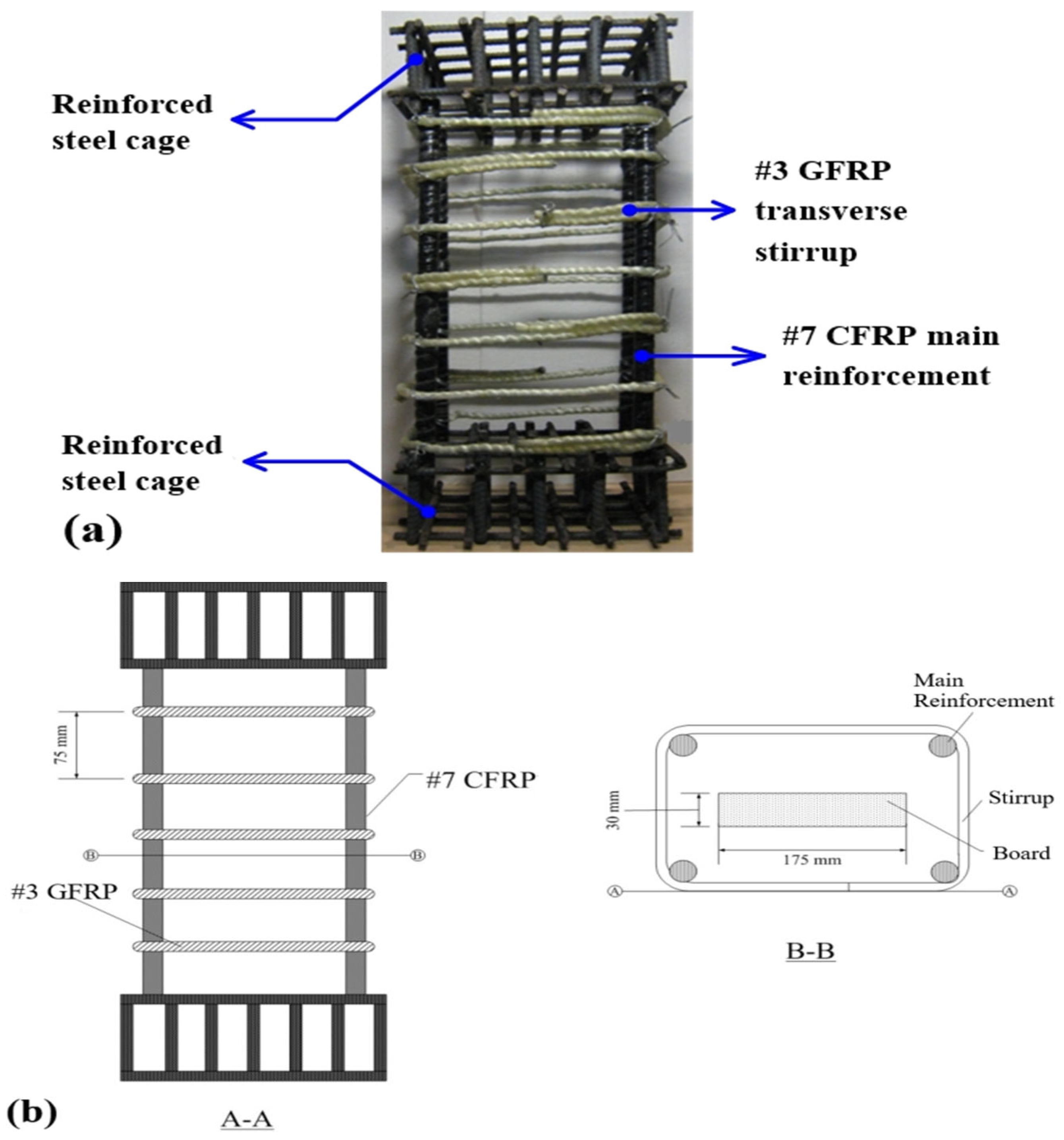
The column specimen designation system was established to clearly indicate reinforcement configuration. Figure 1 shows a detailed description of the reinforcement in a C7G7 rectangular column specimen. The first letter denotes the type of longitudinal reinforcement, where S and C represent steel and CFRP bars, respectively. The first number indicates the bar size of the longitudinal reinforcement. The third letter represents the type of transverse ties, where S, C, and G denote steel, CFRP, and GFRP, respectively. The final number indicates the spacing of transverse ties, where 7 and 15 correspond to 75 mm and 150 mm, respectively. Specimens without transverse reinforcement are denoted accordingly. Specifically, specimens S3 and C7 were unconfined columns with steel and CFRP longitudinal reinforcement, respectively. The remaining specimens were confined using steel, CFRP, or GFRP ties with spacings of either 75 mm or 150 mm. This experimental matrix allows for evaluating the effects of reinforcement type and confinement spacing on column behavior.
To ensure failure occurred within the mid-height region, both ends of the specimens were strengthened using high-strength non-shrink mortar. To prevent the ultimate load capacity of the RC column specimens from exceeding the loading capacity of the hydraulic testing machine, a wooden block with a cross-sectional dimension of 30 × 175 mm was embedded at the center of each column cross-section, as shown in Figure 1b. This embedded wooden block was identical for all specimens and was introduced solely to reduce the maximum axial load during testing. Therefore, it was applied consistently to every specimen and did not affect the comparative evaluation among the different reinforcement configurations. Specimens were cast using ready-mixed concrete with careful vibration to avoid honeycombing, followed by water curing for at least 28 days.

2.3. Test Setup and Instrumentation

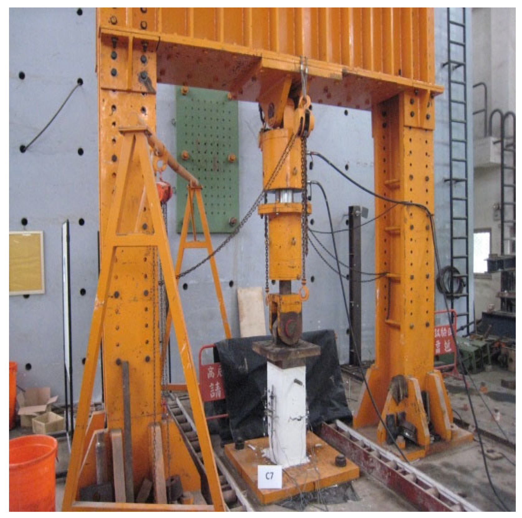
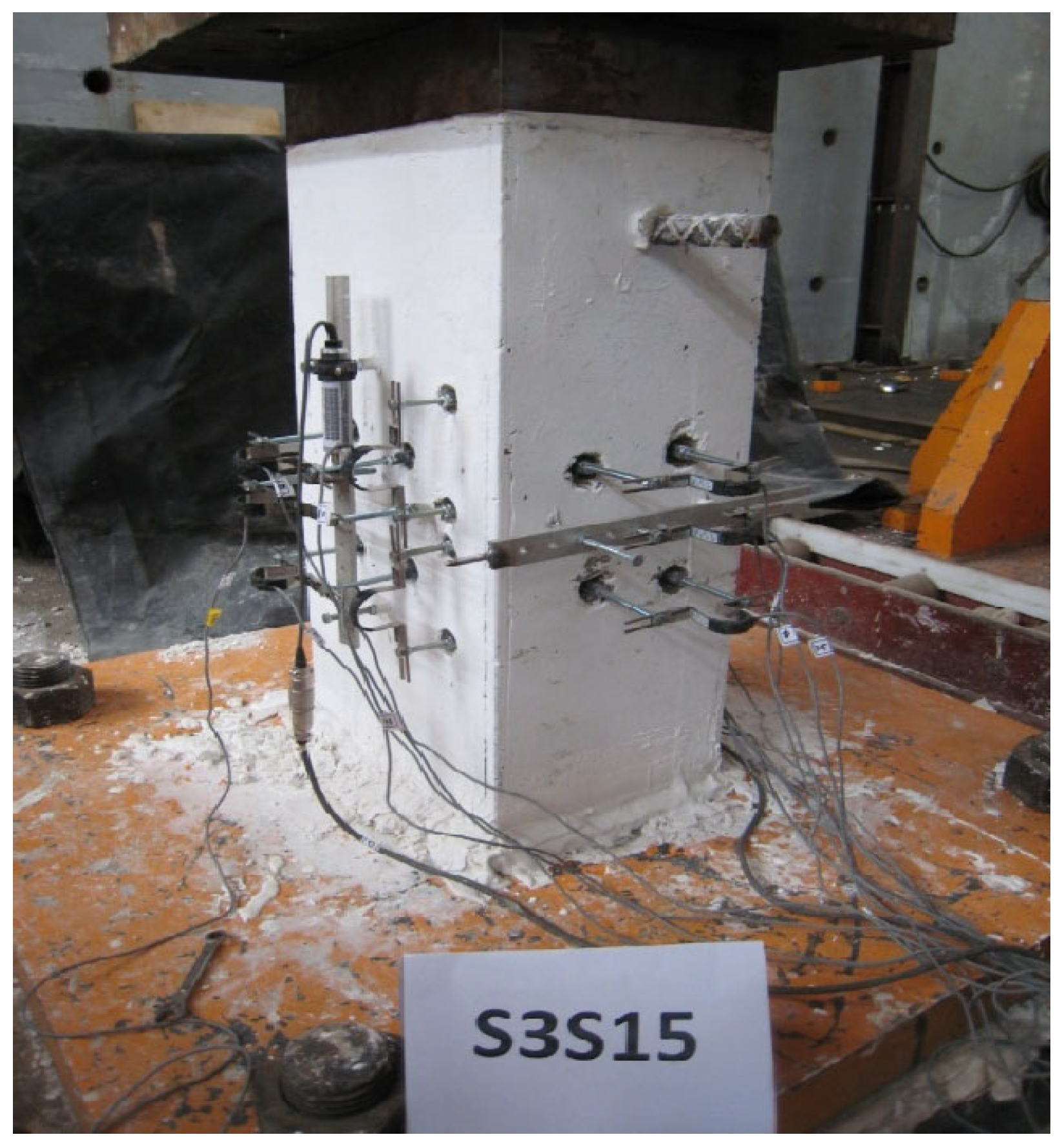
All specimens were tested under concentric axial compression using a hydraulic testing machine. Load was applied through steel bearing plates to ensure uniform stress distribution. Instrumentation included a load cell (350-ton capacity), LVDTs for axial displacement, and strain gauges for measuring longitudinal, transverse, and lateral strains. Data were collected using an automated data acquisition system. All specimens were tested under concentric axial compression using a hydraulic testing machine, as illustrated in Figure 2 and Figure 3. A single-point load was applied at the centroid of the column cross-section through steel bearing plates to ensure uniform stress distribution and to prevent eccentric loading.
An automated data acquisition system was employed throughout the tests, consisting of a computer, a data logger, a load cell (with a capacity of 350 tons), linear variable differential transformers (LVDTs) with a maximum stroke of 10 mm, and π-gauges with a measurement range of ±5 mm. The load cell was used to measure the applied axial load, while LVDTs recorded the axial displacement of the specimens. The π-gauges were installed to monitor lateral strain, transverse tie strain, and longitudinal reinforcement strain.
All measuring devices were calibrated prior to testing. After specimen installation, sensors were connected to the corresponding channels of the data logger and initialized to zero. The system was allowed to stabilize, and testing commenced only when the recorded readings remained within an acceptable error range.

2.4. Testing Procedure

The structural test was performed using a high-capacity servo-hydraulic testing machine under a step-by-step, displacement-controlled quasi-static loading method. To capture structural behaviors and crack propagation accurately, the specific loading and measurement procedures were implemented as follows: Instrumentation Layout: A load cell with a maximum capacity of 3500 kN (350 tons) was integrated with the hydraulic jack to monitor the applied force. To measure structural deformations, linear variable differential transformers (LVDTs, 10 mm maximum stroke) were installed symmetrically on both sides of the specimen to capture axial displacements. Additionally, sixteen Ω-type clip gauges (maximum displacement range of ±5 mm) were mounted sequentially along the longitudinal main reinforcement and transverse stirrups to trace steel strains. Loading Protocol: The experiment was conducted at stepwise quasi-static loading with displacement-controlled actuator operation and intermittent pauses at predetermined load levels for crack observation. The loading process was intentionally paused at predetermined force intervals—approximately every 500 kN during the elastic phase, and reduced to 100 kN intervals as the specimen approached its predicted peak load. While the continuous velocity rate of the actuator was managed manually to maintain the static nature of each step and was not outputted as a continuous time-dependent log, the structural response was strictly governed by the sequential force-interval increments described above.
Prior to testing, specimen surfaces were painted to facilitate crack observation. Axial load was applied incrementally under displacement-controlled conditions. Load was increased stepwise with intermediate holding periods for crack inspection and recording. Near peak load, smaller load increments were used. Testing continued until specimen failure, and the failure modes were documented.

3. Results and Discussion

This study prepared a total of 10 rectangular cross-section concrete short column specimens. To systematically investigate the confinement effect of FRP reinforcement on concrete columns, the specimens were classified according to the type of longitudinal reinforcement and transverse stirrup configuration. The longitudinal reinforcement consisted of S3 (#3 deformed steel bars) and C7 (#7 CFRP bars), while the transverse stirrup configurations included no stirrups, 150 mm spacing, and 75 mm spacing. The S3 and C7 series were evaluated independently because they employed different longitudinal reinforcement types and cross-sectional areas; therefore, comparisons were made only within each series, where the longitudinal reinforcement area and reinforcement ratio remained constant. The measured maximum axial forces and corresponding compressive stresses are summarized in Table 3. The compressive strength of the unconfined concrete (fc′) was 20.21 MPa. In the S3 series, S3S15 exhibited the highest compressive stress of 26.09 MPa, representing a 4.28% increase over the unconfined S3 control specimen (25.02 MPa), whereas S3C15 and S3G15 exhibited peak compressive stresses of 21.48 and 22.66 MPa, respectively. Reducing the stirrup spacing from 150 mm to 75 mm did not result in a systematic increase in peak compressive strength, with S3S7, S3C7, and S3G7 exhibiting similar peak stresses of 22.76, 22.96, and 22.86 MPa, respectively. For the C7 series, the use of GFRP stirrups increased the peak compressive stress from 24.53 MPa for C7 to 26.68 and 25.31 MPa for C7G15 and C7G7, corresponding to increases of 8.76% and 3.18%, respectively.
Overall, the results indicate that the confinement effectiveness of internal FRP stirrups was influenced by stirrup spacing, FRP type, and the associated failure behavior. However, because only one specimen was tested for each configuration, these results should be regarded as experimental observations rather than statistically generalized conclusions. The effects of these variables on the mechanical behavior of the specimens are discussed in the following sections.

3.1. Failure Results of S3 Series Column Specimens

This study included seven specimens, all reinforced with four #3 steel rebars as longitudinal main reinforcement. The aim was to minimize the contribution of the longitudinal main reinforcement to the compressive strength. The steel rebars were S3, S3S15, S3C15, S3G15, S3S7, S3C7, and S3G7.
(1)
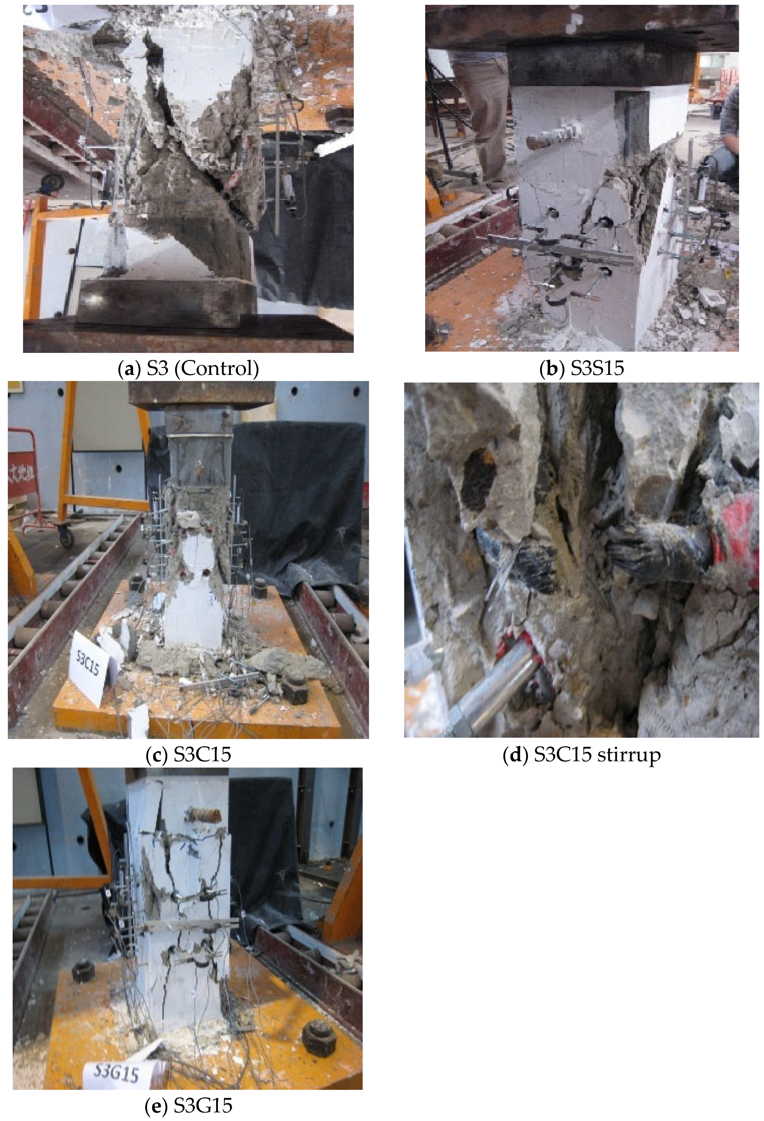
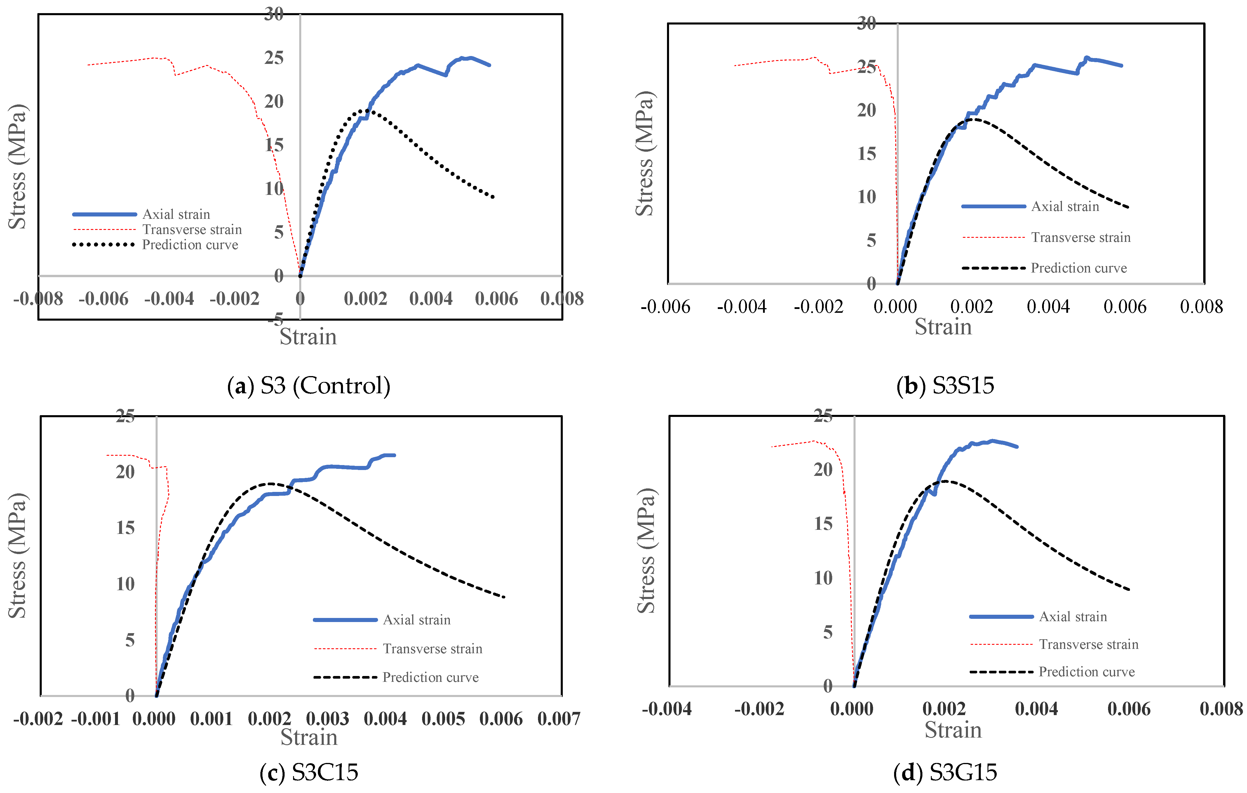
Typical concrete (no stirrups) column specimen: This specimen is made of ordinary concrete. Its stress–strain diagram is shown in Figure 4a, and the photographs of the specimen failure are shown in Figure 5a. When the stress reached 17.1 MPa, the axial strain of the concrete reached 0.2% and the transverse strain reached 0.12%, with no obvious cracks on the specimen surface. When the stress reached 22.9 MPa, the axial strain of the concrete reached 0.36% and the transverse strain reached 0.29%, with only a few cracks on the specimen surface. As the load continued to increase, at 209 tons, the specimen instantly failed and cracked, producing a very obvious diagonal shear crack. At this point, the specimen could no longer bear the axial force, the final axial strain reached 0.58%, and the transverse strain was 0.66%.
(2)
Column specimens with 150 mm stirrup spacing: This group of specimens consists of three pieces: S3S15 (STEEL stirrups), S3C15 (CFRP stirrups), and S3G15 (GFRP stirrups). All specimens have four #3 steel rebars as main reinforcement, and the stirrup spacing is 150 mm. Their concrete stress–strain diagrams are shown in Figure 4b–d. When the stress on the S3S15 specimen reaches 18.9 MPa, the axial strain of the concrete reaches 0.2% and the transverse strain is only 0.0085%. At this point, there are almost no cracks on the specimen surface. When the stress reaches 24.0 MPa, cracks gradually increase on the specimen surface, mainly concentrated in the upper corners. At this point, the axial strain of the concrete has reached 0.35%. With continued pressure, the load increase was limited. Finally, when the stress decreased to 25.3 MPa and the axial strain of the concrete reached 0.58%, the specimen instantly failed and cracked, producing a very obvious diagonal shear crack. The failure photographs are shown in Figure 5b. The experimental results demonstrated that FRP hoops were capable of providing confinement to the concrete core and enhancing the compressive behavior of the column specimens. Similar findings were reported by M. N. Samaan et al. [31], who observed that FRP confinement effectively improved both compressive strength and ductility of concrete columns through lateral restraint of concrete dilation.
For the S3C15 specimen, when the stress reached 17.2 MPa, the axial strain of the concrete reached 0.2% and no obvious cracks were found on the specimen surface. When the stress reached 19.4 MPa s, several cracks appeared on the specimen surface, at which point the axial strain of the concrete was close to 0.3%. With continued pressure, when the stress reached 20.6 MPa, the surface cracks increased sharply, eventually leading to failure and the production of a significant diagonal shear crack. The failure photographs are shown in Figure 5c. Close observation of the failed specimen revealed that one of the CFRP stirrups fractured at the bend, as shown in Figure 5d. One possible explanation is that local deformation or buckling of the longitudinal reinforcement may have contributed to stress concentration at the bent region of the CFRP stirrup. This phenomenon agrees with the findings of Hadi M. N. S. [32], who reported that FRP ties in rectangular columns tend to experience stress concentration at corner regions, especially when brittle CFRP materials are used.
When the stress on the S3G15 specimen reached 17.1 MPa, several inconspicuous cracks appeared on the surface. At this point, the axial strain of the concrete was approximately 0.16% and the transverse strain was approximately 0.02%. At 19.7 MPa, the axial strain reached 0.2% and the transverse strain reached 0.03%, with no significant increase in surface cracks. After continuous pressure exceeding 20.6 MPa, the load gradually could not be increased further, reaching its maximum at 21.7 MPa, and finally cracking failure occurred at 21.3 MPa. The failure diagrams are shown in Figure 5e. At this point, the axial strain of the concrete was approximately 0.35% and the transverse strain was approximately 0.18%. Inspection of the stirrups revealed no signs of breakage or damage.
The experimental observations showed that GFRP stirrups remained intact after failure, whereas CFRP stirrups ruptured prematurely. The better confinement stability of GFRP stirrups may be attributed to their higher ultimate rupture strain. Similar conclusions were reported by De Luca A. et al. [33], who found that GFRP-confined concrete columns exhibited improved deformability and more gradual failure behavior compared with CFRP-confined specimens.
(3)
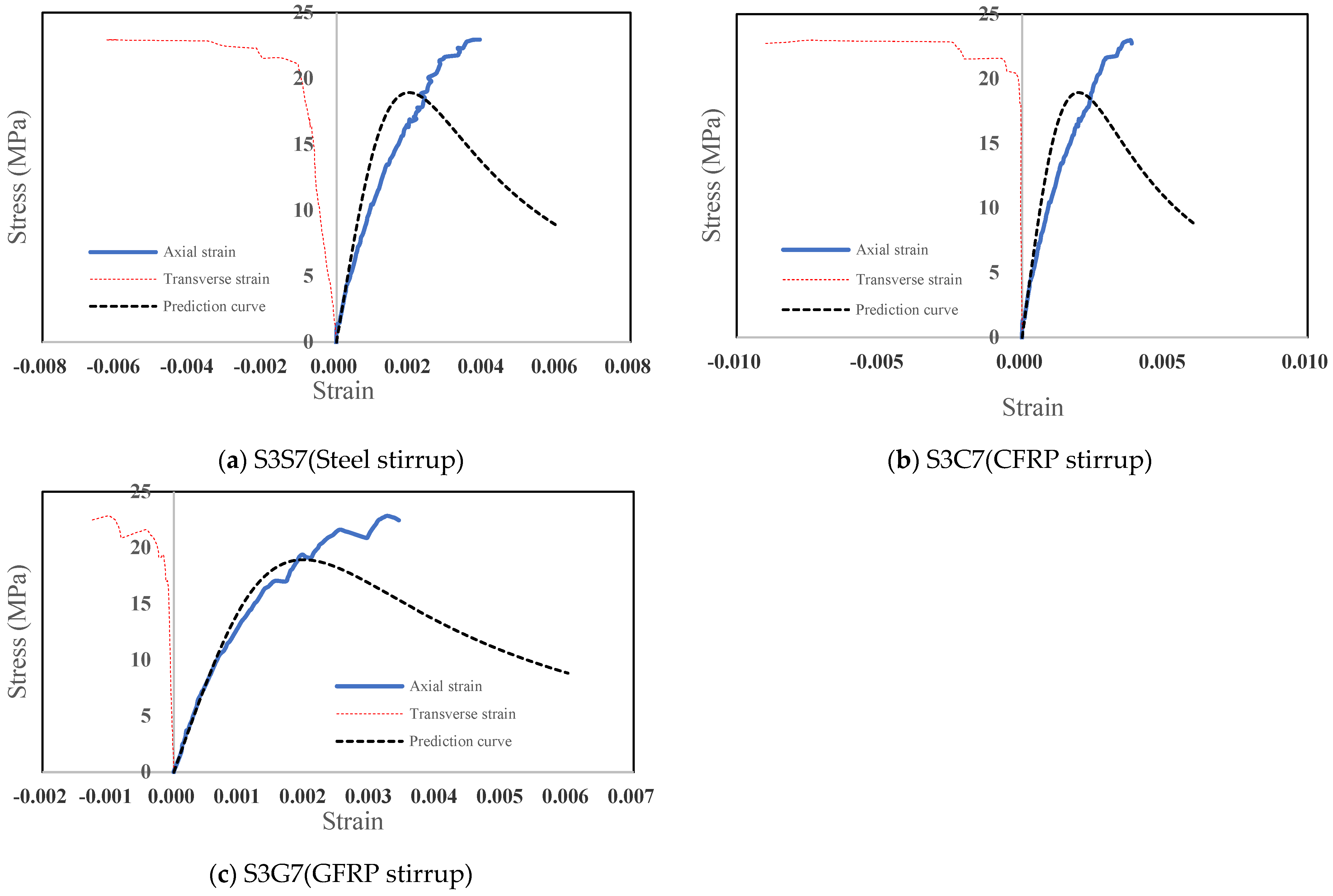
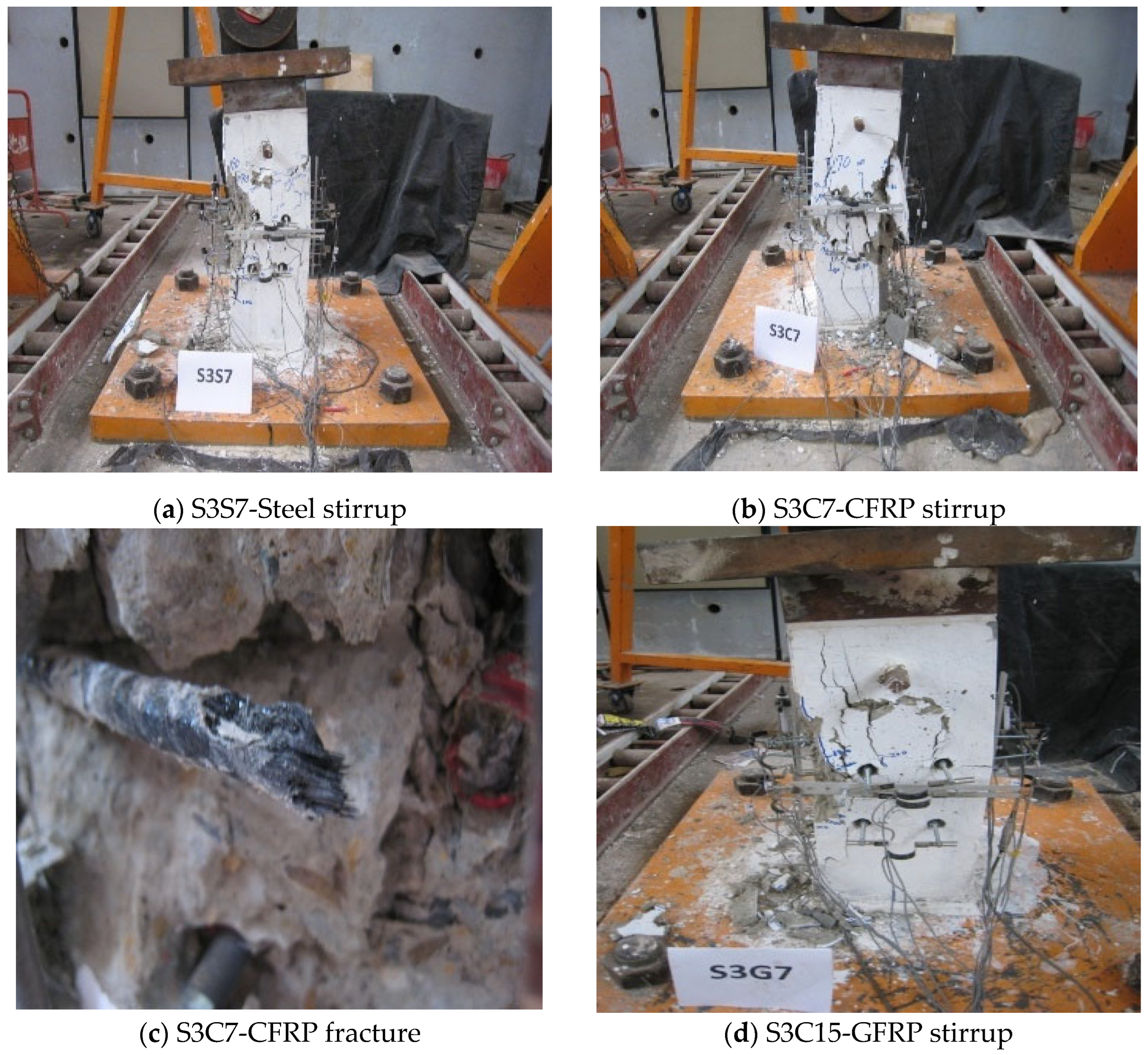
Column specimens with 75mm stirrup spacing: This group consisted of three specimens: S3S7 (steel stirrups), S3C7 (CFRP stirrups), and S3G7 (GFRP stirrups). All specimens were reinforced with four #3 deformed steel longitudinal bars, and the stirrup spacing was 75 mm. The corresponding concrete stress–strain relationships are shown in Figure 6a–c. For specimen S3S7, when the stress reached 16.2 MPa, the axial strain of the concrete was approximately 0.20% and the lateral strain was about 0.028%. When the stress increased to 19.4 MPa, cracks began to appear on the specimen surface, at which point the axial strain reached 0.25% and the lateral strain was approximately 0.054%. At a stress of 21.7 MPa, more pronounced cracks developed and were predominantly concentrated on one side, indicating the possible presence of eccentric loading. Upon further stress to 22.9 MPa, additional cracks formed and the load could no longer increase, with a maximum stress of 23.2 MPa. Finally, when the axial strain reached 0.57% and the lateral strain reached 0.58%, the specimen experienced complete failure. The failure mode was characterized by combined shear and flexural failure, as shown in Figure 7a.
For specimen S3C7, when the stress reached 15.7 MPa, the axial strain of the concrete was approximately 0.20% and no visible cracks were observed on the surface. As the stress increased to 19.4 MPa, cracks gradually appeared and tended to concentrate on one side. This tendency became more pronounced with increasing load, indicating that the specimen was subjected to eccentric loading. When the stress reached 21.7 MPa, further load increase became difficult, and the maximum stress was 22.1 MPa. At failure, the axial strain reached 0.38% and the lateral strain reached 0.90%, and the specimen exhibited complete cracking failure. The failure mode was also governed by combined shear and flexural behavior, as shown in Figure 7b. Close inspection revealed that one CFRP stirrup fractured at the bent corner, as shown in Figure 7c. This was likely due to stress concentration caused by the buckling of the longitudinal reinforcement, leading to rupture of the CFRP stirrup at the bend.
For specimen S3G7, when the stress reached 17.1 MPa, the axial strain was approximately 0.20% and the lateral strain was 0.013%, with no visible cracks observed. At a stress of 19.4 MPa, several cracks began to appear on the surface. As loading continued, the number of cracks increased and tended to localize on one side. When the stress reached 23.3 MPa, the load-carrying capacity began to decrease, followed by complete failure of the specimen. The failure mode was characterized by combined shear and flexural failure, as shown in Figure 7d. At failure, the axial strain was 0.34% and the lateral strain was 0.13%. Examination of the stirrups showed no signs of rupture or damage. The test results indicated that reducing stirrup spacing from 150 mm to 75 mm did not significantly improve compressive strength. This differs from the conventional expectation for steel-confined concrete columns. Similar observations were reported by Wu Y. F. and Wei [34], who suggested that insufficient effective confinement area and premature FRP rupture may limit the benefits of reduced spacing in FRP-confined rectangular columns.

3.2. Failure Results of C7 Series Column Specimens

This study included three column specimens, all using four No. 7 carbon fiber-reinforced polymer (CFRP) bars as longitudinal main reinforcements, to evaluate the contribution of CFRP bars to the compressive strength of the columns. The column specimen numbers were C7, C7G15, and C7G7.
(1)
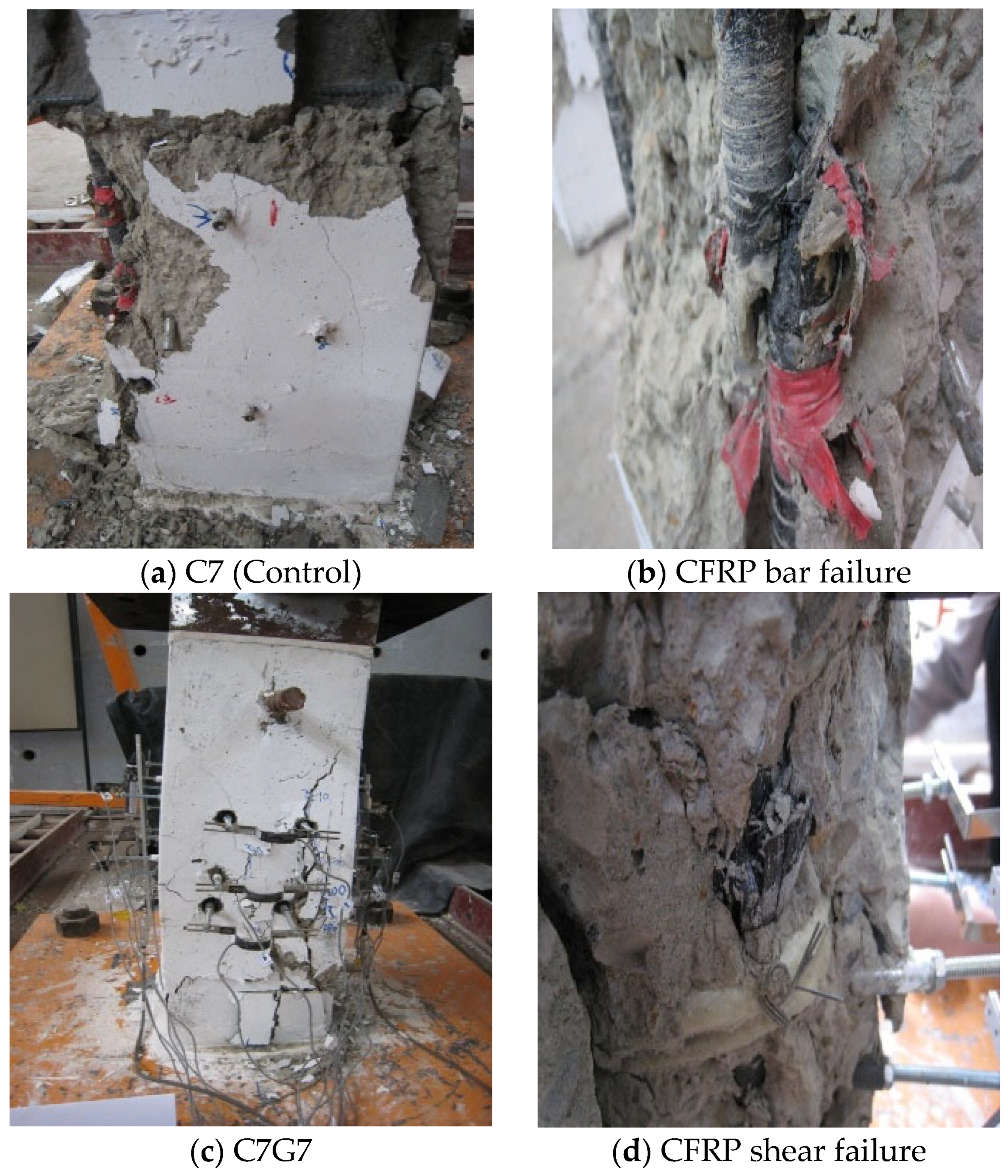
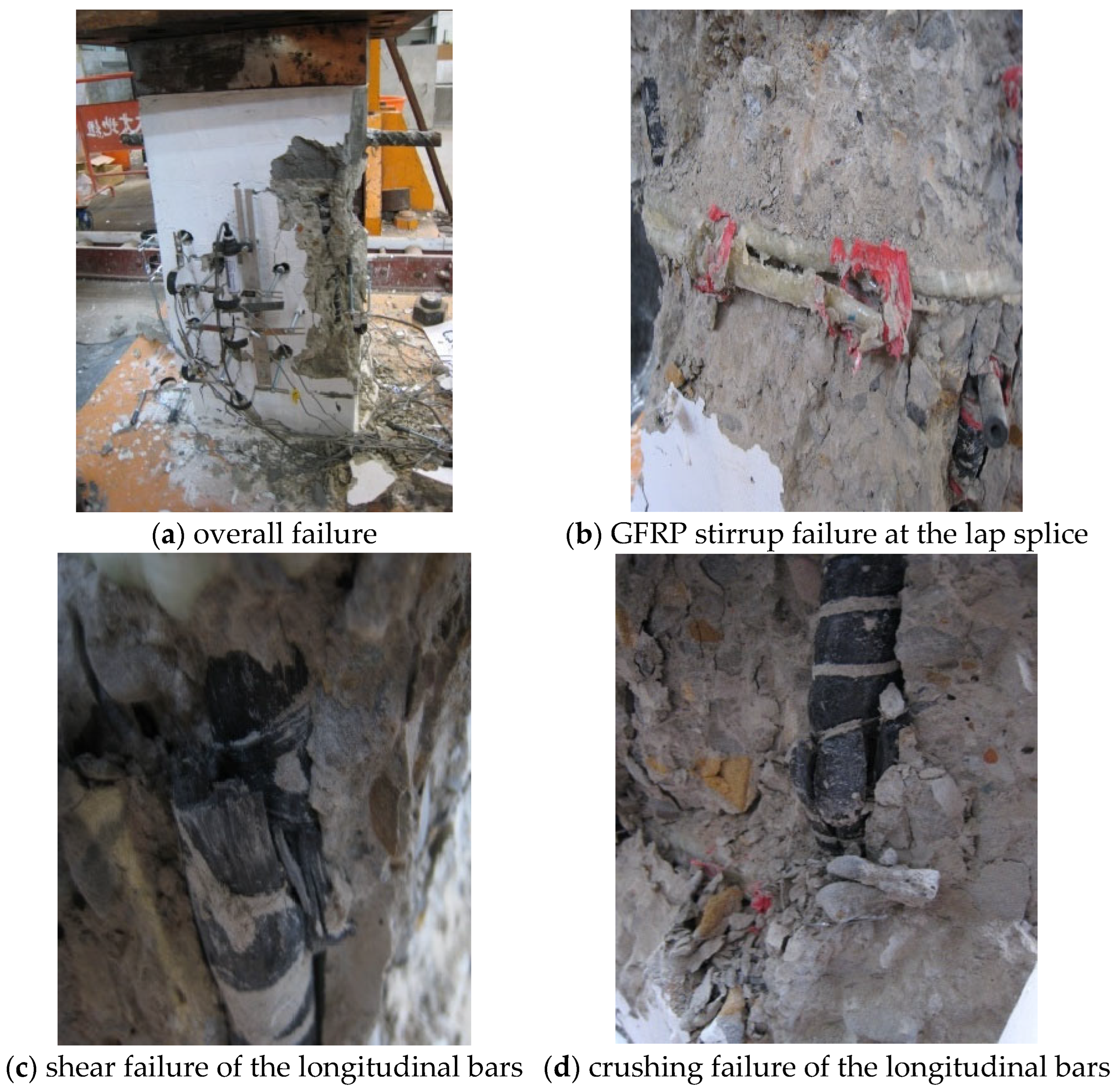
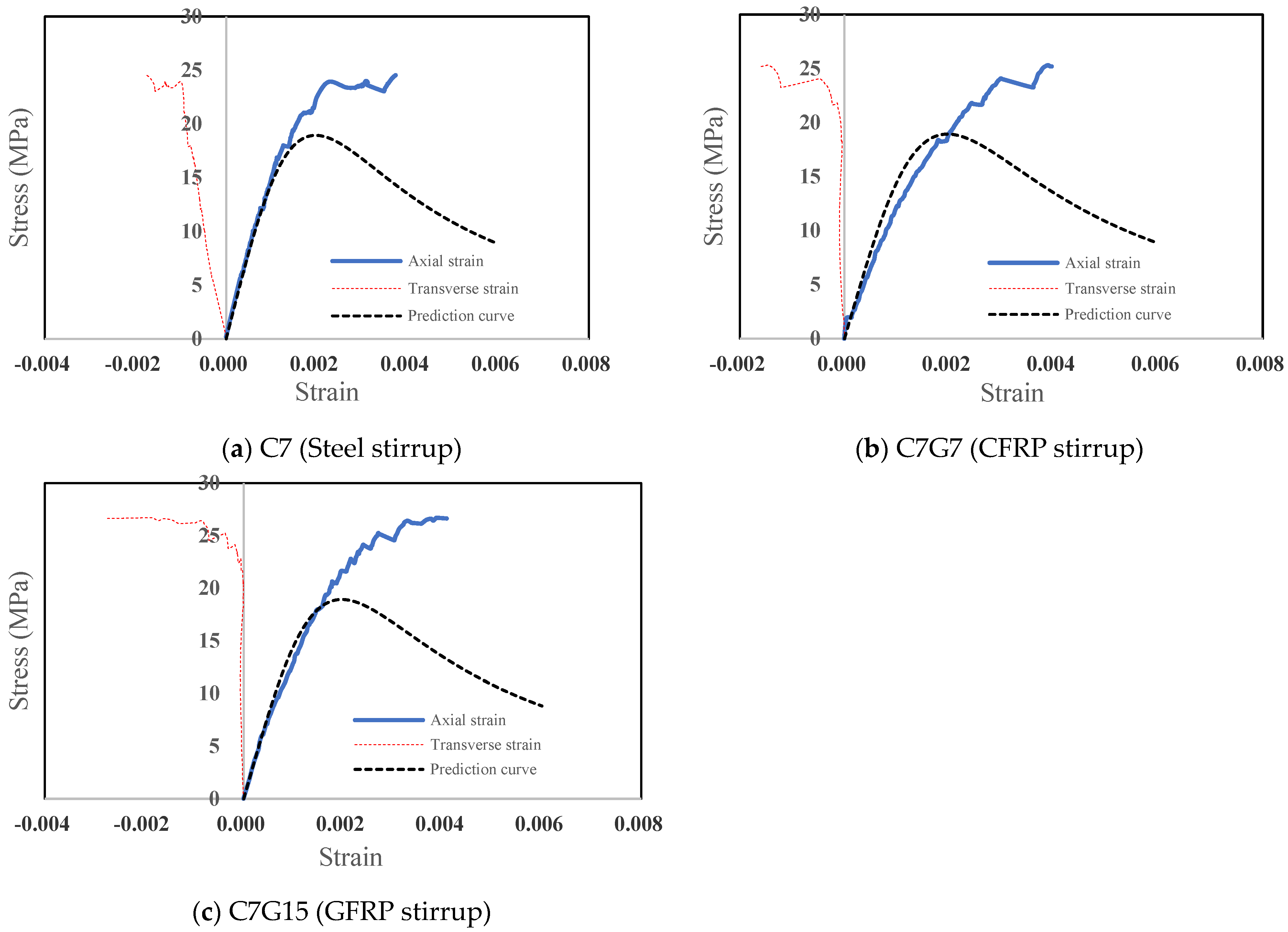
Typical concrete (no stirrups) column specimen: This specimen represents plain concrete without transverse reinforcement. The corresponding stress–strain relationship is shown in Figure 8a, and the failure modes are presented in Figure 9a. When the applied load reached 500 kN and 1000 kN, only minor and barely visible cracks were observed. Significant cracking initiated after the load exceeded 1500 kN. At a stress of 21.1 MPa, the axial strain of the concrete was approximately 0.20%, while the lateral strain was about 0.09%. When the stress increased to 22.6 MPa, the axial strain reached 0.22% and the lateral strain reached 0.10%, accompanied by the appearance of several surface cracks. As the stress continued to increase, the specimen suddenly failed at 24.5 MPa, forming a pronounced diagonal shear crack. At this stage, the specimen completely lost its axial load-carrying capacity. The final axial and lateral strains were 0.37% and 0.17%, respectively. Post-failure inspection revealed that one CFRP bar had been sheared off, as shown in Figure 9b.
(2)
Column Specimens with stirrup: This group consisted of two specimens: C7G15 (stirrup spacing = 150 mm) and C7G7 (stirrup spacing = 75 mm). Both specimens were reinforced with four #7 CFRP longitudinal bars. The stress–strain responses are shown in Figure 8b,c. For specimen C7G7, when the stress reached 17.9 MPa, the axial strain was approximately 0.20% and no visible cracks were observed. At a stress of 22.9 MPa, cracks became more numerous and were concentrated on one side, indicating the presence of eccentric loading. At this stage, the axial strain was 0.30% and the lateral strain was 0.048%. The peak stress was reached at 24.2 MPa, after which the load-carrying capacity began to decrease, followed by failure. The failure mode was characterized by combined shear and flexural failure, as shown in Figure 9c. At failure, the axial strain was 0.39% and the lateral strain was 0.16%. Post-failure examination showed that one CFRP longitudinal bar experienced shear failure, as shown in Figure 9d, while the transverse reinforcement remained intact with no significant damage. For specimen C7G15, when the stress reached 20.6 MPa, the axial strain of the concrete was approximately 0.20% and no visible cracks were observed on the surface. Cracks began to appear only when the stress reached 24.0 MPa, at which point the axial strain was 0.27% and the lateral strain was 0.038%. Upon further stress beyond 25.1 MPa, the load capacity plateaued, and the maximum load reached 2197 kN. The specimen then failed suddenly with cracking, as shown in Figure 10a. At failure, the axial strain was 0.41% and the lateral strain was 0.28%. Detailed inspection revealed that one stirrup failed at the lap splice (rather than at the bend), as shown in Figure 10b, likely due to lateral expansion of the concrete. In addition, the longitudinal CFRP bars exhibited both shear failure and compressive crushing, as shown in Figure 10c,d.
The C7 series specimens demonstrated that the use of CFRP longitudinal bars contributed to the axial load-carrying capacity of the reinforced concrete columns. However, several specimens exhibited combined shear–flexural failure and asymmetric cracking patterns, indicating the presence of unintended eccentric loading during testing. Since no quantitative evaluation of eccentricity was performed using LVDTs or strain gauges, the degree of eccentricity was inferred qualitatively from the observed deformation patterns. Such unintended eccentricity may have affected crack propagation, confinement effectiveness, and the measured ultimate strength. Similar experimental observations have been reported by Liu et al. [35], who showed that FRP confinement can substantially enhance the compressive performance of concrete columns under appropriate confinement conditions, and by Peng et al. [36], who demonstrated that even slight eccentricities in axial compression tests can significantly influence the failure mode, confinement effectiveness, and ultimate load capacity of confined concrete columns. Therefore, the influence of unintended eccentricity should be recognized as a limitation of the present study when interpreting the experimental results.

3.3. Confinement Effects of Different Types of Stirrups

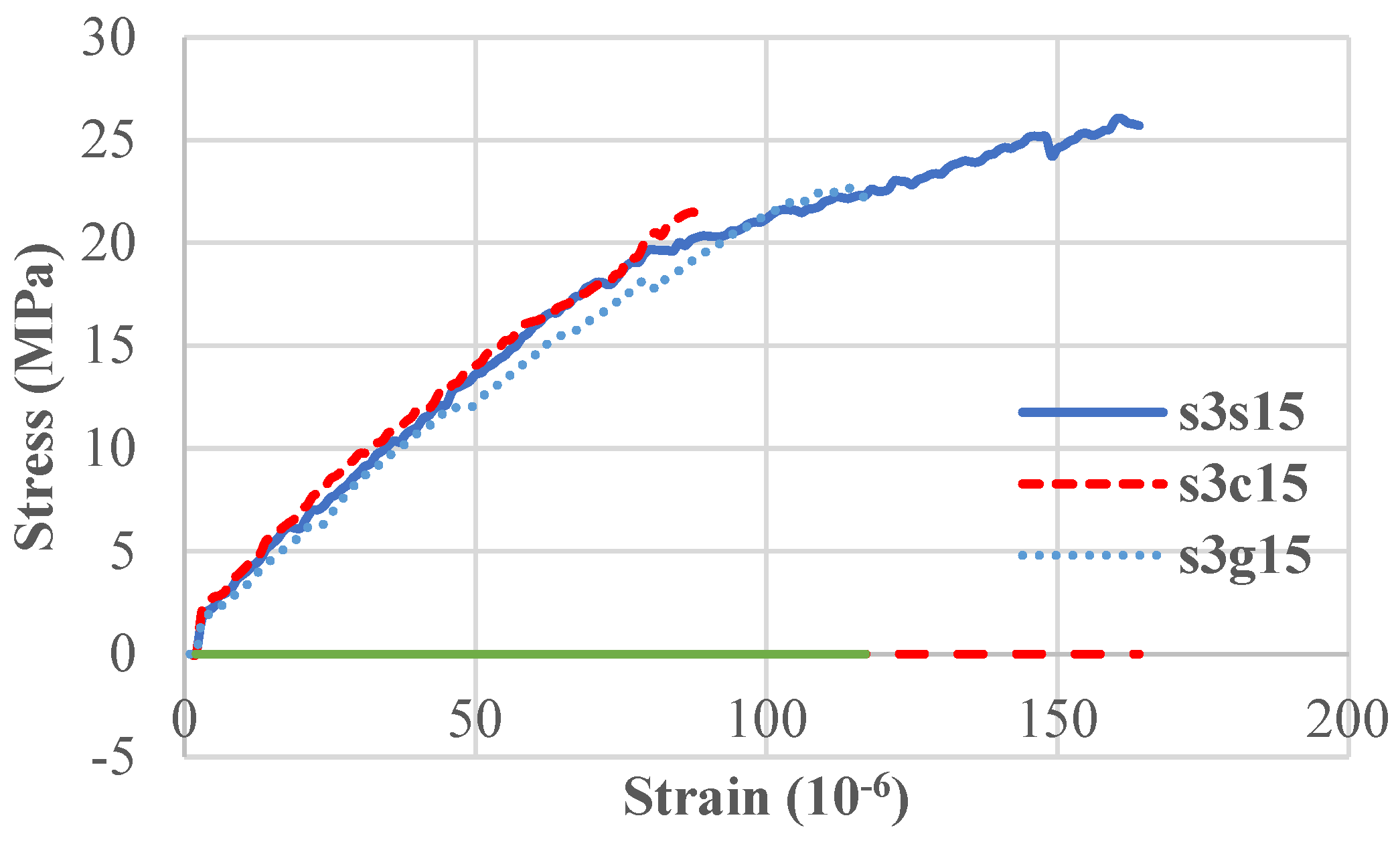
Figure 11 and Figure 12 present the axial stress–strain curves of specimens reinforced with #3 deformed longitudinal bars and stirrup spacings of 150 mm and 75 mm, respectively. As shown in Figure 11, specimen S3S15 exhibited the highest compressive strength, followed by S3G15, whereas S3C15 showed the lowest strength among the three specimens. In terms of deformation behavior, S3S15 exhibited the most stable response, while S3C15 and S3G15 showed similar deformation capacities. This difference may be related to the premature rupture of FRP stirrups at the bent corner regions. The stress concentration developed in the bent regions may have contributed to the observed failure of the CFRP stirrups.
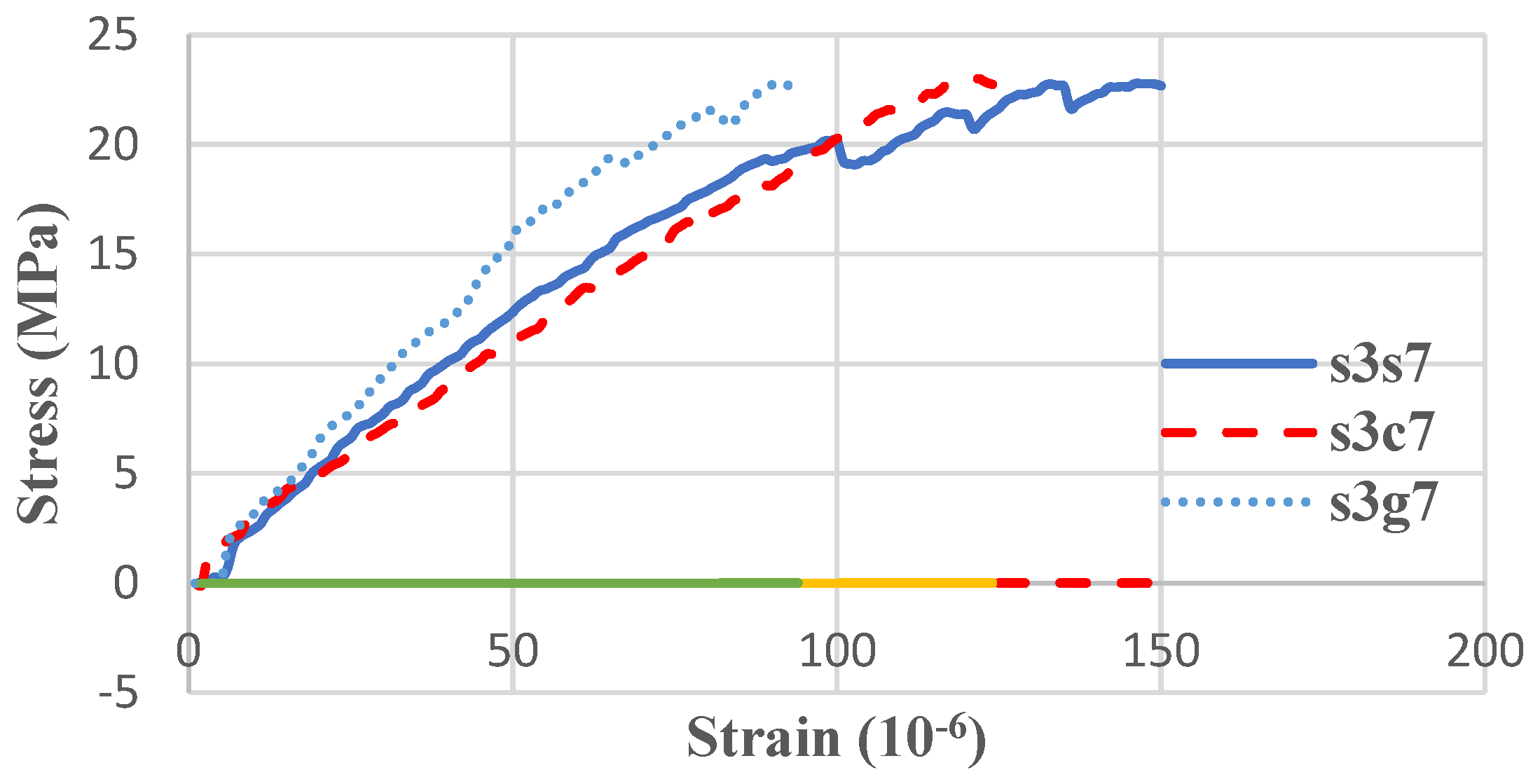
As shown in Figure 12, the three specimens exhibited comparable maximum compressive strengths. Regarding deformation behavior, S3S7 showed a relatively stable response, while S3C7 and S3G7 exhibited similar but slightly reduced deformation capacities. These results were consistent with those obtained from the specimens with 150 mm stirrup spacing, where the FRP stirrups were also influenced by premature failure at the bent regions. Post-test observations revealed that the CFRP stirrups fractured at the bent corners, whereas the GFRP stirrups remained intact. This phenomenon suggests that CFRP stirrups may be more sensitive to stress concentration effects at bent regions, which could reduce their confinement effectiveness under axial compression. Zhiyuan Li et al. [37] similarly concluded that steel-based confinement theories cannot accurately predict FRP-confined concrete behavior and that modified analytical models are required.
From Table 3, it can also be observed that most specimens with a stirrup spacing of 75 mm did not demonstrate higher compressive strengths than those with a spacing of 150 mm. This may be attributed to premature specimen failure, which prevented the full development of confinement effects. In addition, the relatively large stirrup spacing adopted in this study resulted in limited effective confinement regions, reducing the observable influence of transverse reinforcement. Furthermore, unintended eccentricity during testing may have affected crack propagation, failure modes, and the measured ultimate compressive strengths. These factors should be considered when interpreting the experimental results.

3.4. Modified Mander Prediction Model

The confined stress–strain model proposed by Mander et al. [38] was originally developed to predict the behavior of confined core concrete. However, actual reinforced concrete specimens consist of both confined and unconfined concrete regions. In the present study, the proportion of unconfined concrete was relatively large. Therefore, direct application of the original Mander model tends to overestimate the compressive strength of the specimens. To obtain more realistic predictions, the confined core concrete and the surrounding unconfined concrete must be modeled separately.
By combining the stress–strain relationship of unconfined concrete proposed by Popovics [39] (Equation (1)) with the confined concrete model proposed by Mander (Equations (2)–(4)), a modified prediction curve can be established according to the following procedure.
f c = f c 0 × ε c ε c 0 × n n 1 + ( ε c / ε c ) n
where f c 0 is the peak compressive strength of the concrete cylinder specimen, ε c 0 is the strain corresponding to the peak compressive strength, and
n = E c / ( E c E c ) ,
E c = 5000 f c (MPa) is the elastic modulus of concrete, while E c = f c 0 / ε c 0 is the secant modulus of concrete.
The confined concrete parameters were determined based on the rectangular-section confinement model proposed by Mander et al. [38]. The effective lateral confining pressure was first calculated from the geometry and transverse reinforcement of each specimen, and the corresponding confined concrete strength (f’cc) and peak strain (εcc) were then determined according to the Mander model. The unconfined concrete strength (f’c0) was obtained from the concrete material tests, while the corresponding peak strain (εc0) was taken as 0.002, consistent with the Popovics model [39]. These parameters were used in Equations (2)–(4) to establish the modified stress–strain prediction curves.
The stress–strain relationship for confined concrete is expressed as
f c = f c c x r r 1 + x r
where f c c is the compressive strength of confined concrete and f c is the corresponding axial compressive stress.
x = ε c ε c c
r = E c E c E s e c
where E s e c = f c c / ε c c is the secant modulus of confined concrete.

3.4.1. Step 1

Given the values of f c 0 and f c c , a strain range ε c is specified, typically from zero to the concrete strain corresponding to the failure of the first transverse reinforcement. The strain range ε c is then divided into (N) increments.

3.4.2. Step 2

For each strain value ε c = 0 , f c 0 and f c c , Equations (1) and (2) are used to calculate the stresses of unconfined concrete f c 0 and confined concrete f c c , respectively. The predicted compressive stress of the specimen, f c p , can then be determined as Equation (5)
f c p = f c c × A e + f c 0 × A c 0 + ε s × E s × A s A c t
where A e is the effective confined concrete area, A c 0 is the unconfined concrete area excluding longitudinal reinforcement, A s is the area of longitudinal reinforcement, A c t is the total cross-sectional area of the specimen, ε s is the strain of the longitudinal reinforcement, and E s is the elastic modulus of the reinforcement.

3.4.3. Step 3

The procedure described in Step 2 is repeated for each strain increment. Consequently, the complete predicted concrete stress–strain curve can be obtained.
The prediction curves shown in Figure 4, Figure 6 and Figure 8 for the ten rectangular reinforced concrete short-column specimens investigated in this study were established based on the modified Mander confined stress–strain model proposed herein. Comparison between the theoretical prediction curves and the experimental results indicates that the proposed model is generally conservative. It underestimates the peak compressive strength and predicts lower strain values at high stress levels. The relatively rapid loading condition adopted in the present tests may have contributed to the observed difference between the experimental and theoretical responses. However, because the loading-rate effect was not independently investigated in this study, this explanation should be regarded as a possible contributing factor rather than a definitive cause.
The modified stress–strain model adopted herein is based on the models proposed by Mander and Popovics, which were originally developed under quasi-static loading conditions. Therefore, differences between the loading conditions of the present experiments and those assumed in the theoretical models may have contributed to the conservative predictions. In general, relatively high loading rates can increase the measured compressive strength and may also affect the ultimate strain and post-peak response of confined concrete [35]. Table 4 presents the coefficient of determination (R2), mean absolute error (MAE), and root mean square error (RMSE) between the theoretical prediction curves and the experimental results for the ten rectangular reinforced concrete short-column specimens investigated in this study. All three evaluation indices were calculated using the data points before the peak load of the theoretical model. The results in Table 4 indicate that the proposed modified Mander model generally provided a reasonable prediction of the pre-peak response, although the prediction accuracy varied among the specimens. The coefficient of determination ranged from 0.5785 to 0.9217, while the MAE and RMSE ranged from 1.3138 to 2.8253 MPa and from 1.5002 to 4.1322 MPa, respectively. The highest R2 value was obtained for specimen C7 (0.9217), followed by S3G15 (0.9188), S3S15 (0.9096), and C7G7 (0.9105), indicating good agreement between the theoretical and experimental responses before the model-predicted peak. In contrast, specimens S3S7 and S3C7 exhibited relatively lower R2 values of 0.5785 and 0.6032, respectively, together with higher MAE and RMSE values. These results indicate that the model prediction was less accurate for these specimens. Notably, the relatively large difference between the MAE and RMSE values for S3S7 and S3C7 suggests the presence of larger local prediction errors in these cases.
The experimental stress–strain curves further indicate that the specimens exhibited a rapid reduction in load-carrying capacity after reaching the peak compressive strength, whereas the prediction curves retained considerable post-peak load-carrying capacity until the assumed failure of the first transverse reinforcement. Because continuous measurements of the reinforcement strain and failure progression were not available, the exact failure sequence and the degree of confinement mobilization before failure cannot be confirmed. The observed discrepancy may therefore be associated with differences in loading rate, confinement development, and the actual failure progression of the specimens. Similar effects of loading rate on the post-peak behavior and failure characteristics of confined concrete have been reported for dynamically loaded specimens [40]. Accordingly, future improvements to the prediction model should consider the effects of loading rate and the experimentally observed early post-peak response, while recognizing that the proposed failure mechanism remains a possible rather than a confirmed explanation.

4. Conclusions

This study experimentally investigated the confinement effectiveness of FRP reinforcement in rectangular RC short columns subjected to axial compression. Owing to the limited number of specimens, the results should be regarded as preliminary observations rather than statistically conclusive evidence. Based on these experimental observations, the following preliminary findings are presented:
  • The effectiveness of FRP transverse reinforcement depended on the reinforcement configuration and did not consistently improve the peak compressive strength.
  • CFRP longitudinal reinforcement increased the axial load-carrying capacity of the tested columns. Compared with the control specimen C7 (24.5 MPa), specimen C7G15 achieved the highest compressive strength of 26.7 MPa, representing an increase of approximately 8.8%, while specimen C7G7 reached 25.3 MPa, corresponding to an increase of about 3.2%.
  • GFRP stirrups provided confinement performance comparable to, and in some cases better than, that of CFRP stirrups. For specimens with 150 mm stirrup spacing, S3G15 exhibited approximately 5.5% higher compressive strength than S3C15. In addition, no rupture was observed in the GFRP stirrups after failure, whereas all CFRP stirrups fractured at the bent corners.
  • GFRP stirrups maintained their integrity for a longer deformation range in the tested specimens, which was associated with more sustained confinement before failure. Premature rupture of CFRP stirrups limited the confinement effectiveness and reduced the deformation capacity of the specimens. In contrast, GFRP stirrups, owing to their higher rupture strain, maintained better integrity and provided more stable confinement behavior.
  • Reducing the stirrup spacing from 150 mm to 75 mm did not result in a clear improvement in the compressive performance of the tested specimens. For example, the compressive strengths of S3S15 and S3S7 were 26.1 MPa and 22.8 MPa, respectively, while those of S3G15 and S3G7 were 22.7 MPa and 22.8 MPa, respectively. The limited improvement may be associated with premature specimen failure, the effective confinement area, and possible eccentricity or load-alignment effects during testing.
  • The axial strain capacity of confined specimens generally exceeded that of unconfined specimens. The control specimen S3 failed at an axial strain of approximately 0.58%, while specimen S3S15 maintained stable behavior up to a similar strain level with showed a more gradual response near the peak load. Specimens reinforced with FRP stirrups showed reduced deformation capacity when premature stirrup rupture occurred.
  • The experimental observations indicate that the confinement mechanism of FRP reinforcement differs from that of conventional steel reinforcement. Existing confinement models developed primarily for steel-reinforced concrete columns may not fully capture the confinement and failure behavior of FRP-reinforced columns. Dedicated analytical and design models considering the rupture behavior and deformation characteristics of FRP reinforcement are required for reliable structural design.

Author Contributions

Conceptualization, W.-C.W.; Methodology, Y.-C.W. and W.-C.W.; Formal analysis, C.-Y.L.; Investigation, M.-G.L. and W.-C.W.; Resources, Y.-S.C.; Data curation, C.-Y.L.; Writing—original draft, C.-Y.L.; Writing—review & editing, M.-G.L.; Visualization, Y.-S.C.; Supervision, Y.-C.W. and M.-G.L.; Project administration, Y.-C.W. All authors have read and agreed to the published version of the manuscript.

Funding

This research received no external funding.

Data Availability Statement

The raw data supporting the conclusions of this article will be made available by the authors on request.

Conflicts of Interest

The authors declare no conflicts of interest.

References

  1. Wu, W.P. Thermomechanieal Properties of Fiber Reinforced Plastic (FRP) Bars. Ph.D. Thesis, West Viginia University, Morgantown, WV, USA, 1991. [Google Scholar] [CrossRef] [Scilit]
  2. Kobayashi, K.; Fujisaki, T. Compressive Behavior of FRP Reinforcement in Non-Prestressed Concrete Member, Non-Metallic (FRP) Reinforcement for Concrete Structure, 1st ed.; CRC Press: Boca Raton, FL, USA, 1995; pp. 267–274. [Google Scholar]
  3. Deitz, T.H.; Harik, I.E.; Gesund, H. Physical Properties of Glass Fiber Reinforced Polymer Rebars in Compression. J. Compos. Constr. 2003, 7, 363–366. [Google Scholar] [CrossRef] [Scilit]
  4. Mallick, P.K. Fiber Reinforced Composites, Materials, Manufacturing, and Design, 3rd ed.; CRC Press: Boca Raton, FL, USA, 2007. [Google Scholar]
  5. Gong, Y. Research Progress of FRP Reinforced Concrete Column. Archit. Technol. 2006, 37, 836–838. [Google Scholar]
  6. Paramanantham, N. Investigation of the Behavior of Concrete Columns Reinforced with Fiber Plastic Rebar. Master’s Thesis, Lamar University, Beaumont, TX, USA, 1993. [Google Scholar]
  7. Ahmad, S.H.; Shah, S.P. Behavior of Hoop Confined Concrete Under High Strain Rates. ACI J. Proc. 1989, 82, 652–659. [Google Scholar]
  8. Sheikh, S.A.; Tokluku, M.T. Reinforced Concrete Columns Confined by Circular Spirals and Hoops. ACI Struct. J. 1993, 90, 542–553. [Google Scholar] [CrossRef] [Scilit] [PubMed]
  9. Xiao, Y.; Wu, H. Compressive Behavior of Concrete Confined by Carbon Fiber Composite Jackets. J. Mater. Civ. Eng. 2000, 12, 139–146. [Google Scholar] [CrossRef] [Scilit]
  10. GangaRao, H.V.S.; Taly, N.; Vijay, P.V. Reinforced Concrete Design with FRP Composite, 1st ed.; CRC Press: Boca Raton, FL, USA, 2006. [Google Scholar]
  11. Maruyama, T.; Honma, M.; Okamaru, H. Experimental Study on Tensile Strength of Bent Portion of FRP Rods. ACI Spec. Publ. 1993, 138, 163–176. [Google Scholar] [CrossRef] [Scilit] [PubMed]
  12. Nagasaka, T.; Fukuyama, H.; Tanigaki, M. Shear Performance of Concrete Beams Reinforced with FRP Stirrups. ACI Spec. Publ. 1993, 138, 789–811. [Google Scholar] [CrossRef] [Scilit] [PubMed]
  13. El-Sayed, A.K.; El-Salakawy, E.; Benmokrane, B. Mechanical and Structural Characterization of New Carbon FRP Stirrups for Concrete Members. J. Compos. Constr. 2007, 11, 352–362. [Google Scholar] [CrossRef] [Scilit]
  14. ACI Committee 440. Guide for the Design and Construction of Structural Concrete Reinforced with FRP Bars; ACI 440.1R-15; American Concrete Institute: Farmington Hills, MI, USA, 2015. [Google Scholar]
  15. Zeng, J.J.; Lin, G.; Teng, J.G.; Li, L.J. Behavior of large-scale FRP-confined rectangular RC columns under axial compression. Eng. Struct. 2018, 174, 629–645. [Google Scholar] [CrossRef] [Scilit]
  16. Megalooikonomou, K.G.; Papavasileiou, G.S. Analytical Stress-Strain Model for FRP-Confined Rectangular RC Columns. Front. Built Environ. 2019, 5, 39. [Google Scholar] [CrossRef] [Scilit]
  17. Wang, H.; Belarbi, A. Bond-slip behavior between the steel-CFRP composite bar and hybrid fiber-reinforced coral aggregate concrete under monotonic load: Experimental study. Constr. Build. Mater. 2025, 489, 142305. [Google Scholar] [CrossRef] [Scilit]
  18. Wang, C.; Xiao, S.; Zhou, Y.; Xu, Y.; Zhang, F.; Su, T.; Cao, F. Experimental study on the bond-slip behavior between carbonation-modified recycled aggregate concrete and steel bars under dry-wet cycles. J. Build. Eng. 2026, 122, 115729. [Google Scholar] [CrossRef] [Scilit]
  19. Almomani, Y.; Tarawneh, A.; Alawadi, R.; Taqieddin, Z.N.; Taha, S.; Sheikh, N.A.; Momani, Z. Confinement model for circular concrete columns transversely reinforced with GFRP spirals and hoops. Results Eng. 2023, 17, 100918. [Google Scholar] [CrossRef] [Scilit]
  20. Valasaki, M.K.; Papakonstantinou, C.G. Fiber Reinforced Polymer (FRP) Confined Circular Concrete Columns: An Experimental Overview. Buildings 2023, 13, 1248. [Google Scholar] [CrossRef] [Scilit]
  21. Abdallah, A.E.M.; El-Salakawy, E. Confinement properties of GFRP-reinforced concrete circular columns under simulated seismic loading. J. Compos. Constr. 2021, 25, 04020088. [Google Scholar] [CrossRef] [Scilit]
  22. Wang, J.; Lu, L.; Lu, S.; Yang, J. Behavior and modeling of partially CFRP confined reinforced concrete columns under axial compression. Eng. Struct. 2024, 303, 117466. [Google Scholar] [CrossRef] [Scilit]
  23. Yadav, S.K.; Pan, M.; Wang, D.; Wu, D.; Zhao, J. Experimental investigation on the seismic performance of FRP wrap confined FRP reinforced concrete columns. Adv. Struct. Eng. 2026, 0, 13694332261428184. [Google Scholar] [CrossRef] [Scilit]
  24. Tran, H.; Nguyen-Thoi, T.; Dinh, H.-B. State-of-the-art review of studies on the flexural behavior and design of FRP-reinforced concrete beams. Materials 2025, 18, 3295. [Google Scholar] [CrossRef] [Scilit] [PubMed]
  25. Wang, M.; Wang, Y.; Chen, G. Bond-slip law for the analysis of ribbed steel-FRP composite bars embedded into FRP-confined concrete. Eng. Struct. 2025, 339, 120672. [Google Scholar] [CrossRef] [Scilit]
  26. Wang, M.; Wang, Y.; Zhang, X.; Chen, G. Bond behavior and bond strength model for ribbed FRP bar in FRP-confined concrete. Constr. Build. Mater. 2024, 389, 138318. [Google Scholar] [CrossRef] [Scilit]
  27. Liu, X.; Li, M.; Wei, H.; Tian, X.; Ding, Y. Axial compression performance of CFRP-confined lightweight aggregate concrete reinforced with hybrid fibers. J. Build. Eng. 2025, 113, 113972. [Google Scholar] [CrossRef] [Scilit]
  28. Jaitrong, J.; Thongchom, C. Behavior and performance of GFRP-reinforced concrete columns confined with CFRP under concentric and eccentric loading. Structures 2025, 79, 109528. [Google Scholar] [CrossRef] [Scilit]
  29. ACI Committee 440. Guide for the Design and Construction of Structural Concrete Reinforced with FRP Bars; ACI 440.2R-17; American Concrete Institute: Farmington Hills, MI, USA, 2017. [Google Scholar]
  30. ASTM C150/C150M-22; Specification for Portland Cement. ASTM International: West Conshohocken, PA, USA, 2022.
  31. Samaan, M.; Mirmiran, A.; Shahawy, M. Model of concrete confined by fiber composites. J. Struct. Eng. ASCE 1998, 124, 1025–1031. [Google Scholar] [CrossRef] [Scilit]
  32. Hadi, M.N.S. Behavior of FRP wrapped normal strength concrete columns under eccentric loading. Compos. Struct. 2006, 72, 503–511. [Google Scholar] [CrossRef] [Scilit]
  33. De Luca, A.; Matta, F.; Nanni, A. Behavior of full-scale glass fiber-reinforced polymer reinforced concrete columns under axial load. ACI Struct. J. 2010, 107, 589–596. [Google Scholar] [CrossRef] [Scilit]
  34. Wu, Y.F.; Wei, Y.Y. Effect of cross-sectional aspect ratio on the strength of CFRP-confined rectangular concrete columns. Eng. Struct. 2010, 32, 32–45. [Google Scholar] [CrossRef] [Scilit]
  35. Liu, Z.; Sun, C.; Qu, J.; Mokhov, A. State-of-the-Art Review of the Performance of Fiber-Reinforced-Composite-Confined Concrete Columns at Ambient Temperatures. Materials 2025, 18, 1151. [Google Scholar] [CrossRef] [Scilit] [PubMed]
  36. Peng, G.; Hu, X.; Niu, D.; Zhang, Y.; Zhong, S. Study on the axial compression behavior of RC columns strengthened with cementitious grout. Eng. Struct. 2023, 284, 115742. [Google Scholar] [CrossRef] [Scilit]
  37. Li, Z.; Feng, P.; Yang, J.-Q. Analysis-oriented model for FRP tube-confined concrete: 3D interpretation of biaxial tube behaviour. Eng. Struct. 2022, 272, 114987. [Google Scholar] [CrossRef] [Scilit]
  38. Mander, J.B.; Priestley, M.J.N.; Park, R. Theoretical Stress-Strain Model for Confined Concrete. J. Struct. Eng. 1988, 114, 1804–1826. [Google Scholar] [CrossRef] [Scilit]
  39. Popovics, S. A Numerical Approach to the Complete Stress-Strain Curves for Concrete. Cem. Concr. Res. 1973, 3, 583–599. [Google Scholar] [CrossRef] [Scilit]
  40. Ren, X.; Liu, K.; Li, J.; Gao, X. Compressive behavior of stirrup-confined concrete under dynamic loading. Constr. Build. Mater. 2017, 154, 10–22. [Google Scholar] [CrossRef] [Scilit]
Figure 1. Reinforcement details of the C7G7 rectangular column specimen: (a) Overall reinforcement condition, (b) Reinforcement configuration and longitudinal section of the specimen.
Jcs 10 00444 g001
Figure 2. Column specimen test site setup.
Jcs 10 00444 g002
Figure 3. Measuring column specimen instrument setup (the instrument configurations on the other two sides are the same).
Jcs 10 00444 g003
Figure 4. Stress–strain diagrams for S3, S3S15, S3C15 and S3G15 series column specimens.
Jcs 10 00444 g004
Figure 5. Cracking failure diagrams for S3, S3S15, S3C15 and S3G15 series column specimens.
Jcs 10 00444 g005
Figure 6. Stress–strain diagrams for S3S7, S3C7, and S3G7 series column specimens.
Jcs 10 00444 g006
Figure 7. Cracking failure diagrams for S3S7, S3C7, and S3G7 series column specimens.
Jcs 10 00444 g007
Figure 8. Stress–strain diagrams for C7, C7G7, and C7G15 series column specimens.
Jcs 10 00444 g008
Figure 9. Cracking failure diagrams for C7 and C7G7 series column specimens.
Jcs 10 00444 g009
Figure 10. Cracking failure diagrams for C7G15 series column specimens.
Jcs 10 00444 g010
Figure 11. Stress–strain diagram for S3x15 (stirrup spacing 150 mm) specimens.
Jcs 10 00444 g011
Figure 12. Stress–strain diagram for S3x7 (stirrup spacing 75 mm) specimens.
Jcs 10 00444 g012
Table 1. Details of material properties of steel wire, steel rebar, CFRP and GFRP bars.
Rebar GradeNominal Diameter (cm)Nominal Cross-Section Area (cm2)Elastic Modulus (GPa)Ultimate Strength (fu)
Kgf/cm2MPa
D6 steel wire0.6000.28272065397529
#3 steel0.9530.7132065435533
#3 CFRP0.9530.8571384328424
#3 GFRP0.9530.907396728660
#4 CFRP1.2701.6111384956424
#7 GFRP2.2233.780395975586
#7 CFRP2.2234.03613811,6671143
Table 2. Details of ten rectangular column specimens.
# SpecimenType of Longitudinal Main Reinforcement# Longitudinal Main ReinforcementType of Transverse Stirrup (#3)Spacing of Transverse Stirrup (mm)
S3Steel#3 barnonenone
C7CFRP#7 barnonenone
S3S7Steel#3 barSteel75
S3C7Steel#3 barCFRP75
S3G7Steel#3 barGFRP75
C7G7CFRP#7 barGFRP75
S3S15Steel#3 barSteel150
S3C15Steel#3 barCFRP150
S3G15Steel#3 barGFRP150
C7G15CFRP#7 barGFRP150
Table 3. Result for maximum compressive strength f c c of the ten column specimens.
Column SpecimenMaximum Axial Force (kN) f c c   (MPa) f c c / f c 0
S3 (Control group)2049.5925.021.24
S3S152137.8526.091.29
S3C151765.2021.481.06
S3G151863.2622.661.12
S3S71990.7522.761.13
S3C71892.6822.961.14
S3G72000.5622.861.13
C7 (Control group)2020.1724.531.21
C7G152196.6926.681.32
C7G72079.0125.311.25
Note: Strength of unbound concrete f c 0 = 20.21 MPa.
Table 4. Coefficient of determination (R2), MAE, and RMSE between the theoretical prediction curves and experimental results for the ten column specimens.
Column SpecimenR2MAE (MPa)RMSE (MPa)
S3 (Control group)0.86861.64181.8589
S3S150.90961.32531.5291
S3C150.85391.51251.7912
S3G150.91881.31381.5002
S3S70.57852.82534.1322
S3C70.60322.52593.7224
S3G70.81562.09962.4813
C7 (Control group)0.92171.41531.7121
C7G150.82191.91682.3992
C7G70.91051.39911.6105
Disclaimer/Publisher’s Note: The statements, opinions and data contained in all publications are solely those of the individual author(s) and contributor(s) and not of MDPI and/or the editor(s). MDPI and/or the editor(s) disclaim responsibility for any injury to people or property resulting from any ideas, methods, instructions or products referred to in the content.