Article

Sectional and Stress Analysis of Hybrid Reinforced Concrete Beams with Embedded GFRP Profiles Under Monotonic Static Loading

1
Department of Civil Engineering, University of Baghdad, Baghdad 17001, Iraq
2
L2MGC-Laboratoire de Mécanique et Matériaux du Génie Civil, CY Cergy-Paris University, 95031 Neuville-sur-Oise, France
*
Author to whom correspondence should be addressed.
J. Compos. Sci. 2026, 10(6), 288; https://doi.org/10.3390/jcs10060288
Submission received: 16 April 2026 / Revised: 15 May 2026 / Accepted: 21 May 2026 / Published: 25 May 2026
(This article belongs to the Special Issue Concrete Composites in Hybrid Structures)

Abstract

Glass fiber–reinforced polymer (GFRP) reinforcement provides an effective alternative to conventional steel in concrete structures due to its corrosion resistance. Nevertheless, the lower elastic modulus of GFRP necessitates careful consideration of serviceability behavior in GFRP-reinforced concrete members. This study presents a numerical sectional analysis model for predicting the flexural response and ultimate capacity of hybrid reinforced concrete beams incorporating embedded GFRP profiles in combination with either mild steel or GFRP reinforcement bars under monotonic static loading. The proposed model employs realistic nonlinear stress–strain relationships for concrete and steel, together with secant moduli of elasticity evaluated at different loading stages. Particular emphasis is placed on detailed stress distribution in flexural sections, including the contribution of tension stiffening in the post-cracking regime. The formulation integrates nonlinear constitutive material behavior with theoretical sectional equilibrium to evaluate the effective flexural secant stiffness. For practical serviceability assessment and to reduce dependence on complex analytical procedures, strain vectors and stiffness matrix components are derived using elasticity coefficients that reflect modulus degradation obtained from numerical analysis. The accuracy of the model is verified through comparison with experimental results, including ultimate flexural capacity and moment–deflection responses. Many crucial parameters were studied, such as the longitudinal reinforcement ratio, type of reinforcement, concrete compressive strength, position of the I-GFRP profile, and rotation of the I-GFRP profile. The results of this study demonstrated that both the longitudinal reinforcement ratio and the rotation of the I-GFRP profile have a significant influence on the ultimate load capacity and deflection behavior. The close agreement between numerical predictions and experimental observations demonstrates the reliability and applicability of the proposed model for structural engineering analysis and design.

1. Introduction

Deterioration due to corrosion of steel reinforcement is a continuing problem for reinforced concrete (RC) structures exposed to aggressive and damaging environments. Loss of service life as a result of corrosion leads to increased maintenance and repair costs for RC structures. Fiber-reinforced polymer (FRP) bars have emerged as an exciting alternative to conventional steel reinforcement in civil engineering applications over the past ten years. FRP materials provide beneficial properties that make them desirable. The three primary features of FRP bars are a high strength-to-weight ratio, corrosion resistance, and reduced weight compared to steel. Generally, FRP bars consist of glass, carbon, aramid, or metallic fibers embedded in a polymeric resin matrix, which may be polyester, phenolic, vinylester, acrylic, and epoxy resins [1,2,3,4,5].
Due to their many advantages, including lightness, tensile strength, resistance to chemicals and corrosion, and electrical insulation properties, glass fiber polymer composite (GFRP) materials are becoming increasingly accepted as an alternative to steel bars, profiles and plates in RC structures [6,7,8,9,10]. However, because of the low Young’s and shear moduli of GFRP materials [11,12,13,14], members reinforced with GFRP may experience higher levels of deformation and lower levels of stiffness under high service load or ultimate load conditions.
To overcome these limitations, the use of hybrid structural systems (those that combine FRP components with a reinforced concrete system) has been proposed and has been shown to improve the load-carrying capacity and performance of structures [15,16,17,18,19]. Additionally, the mechanical weakness of the GFRP composite material can be improved by combining it with conventional reinforcement [20] or other cementitious composite materials [21]. As a result, pultruded FRP components (profiles) embedded within concrete elements are receiving significant attention from researchers, as evidenced by the large volume of both experimental and numerical research that has been published in the literature regarding this type of structural component. In addition, the concrete-filled glass fiber–reinforced polymer (GFRP) box can be applicable in many structural buildings as it acts as a stay-in-place formwork with reduced cost and time. The GFRP box provides confinement of concrete, as well as increased strength when exposed to corrosive environments. Many studies have used the GFRP box members in both flexural [22,23] and axial applications [24].
The flexural performance of GFRP-polymer concrete hybrid beams designed with three different standard pultruded GFRP U-shaped profiles was experimentally tested by Ferreira et al. [25] under static loading and numerically modeled to assist in the evaluation of this flexural performance. The findings indicated a better composite interaction between the GFRP and polymer concrete constituents that exceeded expectations, as well as an increase in the overall structural performance of the GFRP-polymer concrete hybrid beams.
Correia and coworkers [26] conducted experiments on a simply supported beam with a GFRP profile, connected to concrete with either steel bolts or an epoxy bonding layer, and subjected to bending with varying effective spans. They carried out various investigations regarding the performance of hybrid beams based on the type and configuration of the supports utilized. The results of their tests indicate that hybrid beams produced with GFRP–concrete exhibit increased stiffness and strength compared with hybrid beams manufactured from only GFRP profiles. Furthermore, a continuous epoxy bonding layer achieved increased stiffness compared to the bonded connection achieved using steel bolts. Therefore, it can be determined that a connection made using an epoxy bonding layer will produce a smaller overall deflection and a greater level of flexural strength than GFRP hybrid beams.
Evbuomwan [27] studied the use of different forms of FRP in composite beams, including varying parameters such as type of concrete (normal or lightweight), bonding systems (epoxy adhesive or mechanical bolts), and FRP section configuration (rectangular and I-sections). The experimental results showed that the composite beams exhibited higher ultimate failure loads than the plain GFRP beams. The use of epoxy adhesive and/or mechanical connectors (bolts) ensured adequate composite action.
Neagoe et al. [28] experimentally evaluated hybrid beams composed of pultruded GFRP profiles encased in concrete and reported high flexural capacity-to-self-weight ratios and improved bending resistance. However, they also noted reduced flexural stiffness compared to conventional RC beams, primarily due to the low elastic modulus of GFRP and partial interaction effects.
Hadi and Yuan [29] experimentally investigated RC beams incorporating pultruded GFRP I-profiles encased in concrete and reinforced with longitudinal steel or GFRP bars under four-point bending. Their results showed that beams reinforced with steel bars achieved higher ultimate load and ductility compared to conventional RC beams, whereas beams reinforced with GFRP bars exhibited brittle failure and reduced stiffness and load capacity. Also, it was observed that the location of the GFRP I-profile had little effect on the flexural response. Madenci et al. [30] conducted experimental, theoretical, and finite-element analyses on pultruded GFRP beams subjected to three-point bending, reporting close agreement between predicted data and experimental results. Using epoxy adhesive and/or mechanical connectors (bolts) ensured adequate composite action. Gemi et al. [22] investigated experimentally, analytically, and numerically the behavior of pultruded GFRP composite beams infilled with hybrid fiber-reinforced concrete under four-point loading. The experimental variables included the pultruded GFRP box profiles, conventional steel bars, GFRP bars, hybrid bars, and the external GFRP wrapping. The results demonstrated that the hybrid-bar specimens exhibited the best performance in terms of energy dissipation capacity and maximum load capacity when reinforced concrete was used in the pultruded profile. In addition, the presence of pultruded GFRP increased the initial stiffness of the beam. Therefore, the pultruded profile significantly enhanced the behavior of traditional reinforced concrete beams, and GFRP composite wrapping also considerably improved the behavior of the pultruded profile infilled with a reinforced concrete beam.
Ibrahim et al. [31] studied the experimental and numerical response of reinforced concrete (RC) composite specimens with encased pultruded I-GFRP sections under three-point loading. The study addressed the effect of using the shear connector between the GFRP beams and concrete to improve the composite action. The results reveal that the ultimate load of the embedded GFRP beam increased by 65% and 51% for the composite specimens with and without shear connectors, respectively. Moreover, a nonlinear Finite Element (FE) model was developed and validated by the experimental results to conduct a parametric study. The peak loads of the composite specimen without shear studs increased by 14% and 31%, and that of the composite specimen with shear studs increased by 20% and 32% for the compressive strength of 35 MPa and 45 MPa, respectively.
Although there has been a significant amount of both experimental and numerical research on GFRP–concrete hybrid beams, the majority of research has been generated from full-scale experimental tests and detailed finite element simulations. Both of these types of studies are valuable sources of information, but, unfortunately, they represent computationally intensive methodologies that are not necessarily practical for everyday use as a design. On the other hand, few studies have considered the application of simplified, yet still reliable, section-based numerical models to provide a complete representation of certain critical aspects of flexural behavior within a unified analytical framework. These aspects include stiffness reduction, cracking development, tension stiffening influence, and ultimate flexural capacity. The inadequacy of existing studies becomes more apparent in the case of hybrid reinforced concrete beams with embedded GFRP profiles. In these cases, the flexural response of the hybrid system, including the stress redistribution and stiffness evolution of the concrete, either internal steel or GFRP reinforcement, and the embedded pultruded performance, dictates the flexural behavior of the hybrid system when subjected to flexural loading.
In order to adequately address the need for rational section analysis methods to predict the nonlinear flexural behavior of hybrid systems in a computationally efficient manner and in a manner that can provide acceptable results for serviceability and strength evaluations, additional research is required.
Accordingly, this research work studies hybrid RC beams with embedded GFRP profiles and their numerical behavior using the sectional analysis methodology introduced in [32] by Oukaili. The FORTRAN program presented in [33] by Oukaili has been rewritten and modified in MATLAB R2022a for easier use and to enable efficient performance of further investigation and implementation.
The novelty of the proposed model lies in its unified and generalized sectional formulation, in which the existing constitutive and sectional equilibrium frameworks are extended into a single consistent nonlinear analysis procedure capable of handling multiple reinforcement configurations and cross-sectional geometries. Specifically, the model integrates steel reinforcement, GFRP bars, and embedded GFRP I-sections within a single strain compatibility and equilibrium framework, rather than treating them as separate specialized cases.
In addition, the formulation is generalized to accommodate both rectangular and circular cross-sections within the same computational structure, allowing a unified treatment of hybrid reinforced concrete members under monotonic loading. This represents an extension beyond the original formulations, which were limited to more specific configurations.
The proposed numerical model has been validated through comparison with the available experimental data, specifically by evaluating the ultimate moment capacity, midspan deflection and overall load–deflection performance responses.
Additionally, unlike previous investigations that depended primarily on testing programs or detailed finite element modeling, this work develops a unified nonlinear formulation for a secant-stiffness sectional analysis that explicitly integrates embedded pultruded GFRP profiles within the cross-sectional equilibrium approach. The proposed model predicts stiffness degradation, crack initiation and propagation, tension stiffening, and reinforcement interaction influences in a computationally efficient manner suitable for practical design applications. Additionally, the effects of GFRP profile rotation and positioning are systematically evaluated, providing new insights into optimizing hybrid concrete beams incorporating GFRP components.

2. Numerical Model and Sectional Analysis

Concrete structural members may be analyzed using discrete numerical approaches or through cross-sectional (sectional) analysis concepts. Several researchers, including Oukaili [32,33], Kawakami et al. [34,35], and Rodríguez-Gutiérrez et al. [36], have investigated the strength and deformation behavior of structural concrete cross-sections using sectional formulations. In contrast to approaches based on tangential sectional stiffness, Oukaili [32,33] proposed an iterative sectional analysis procedure founded on the use of secant sectional stiffness. Compared with tangential stiffness–based methods, secant stiffness approaches exhibit improved numerical convergence and are simpler to implement in practical applications.
In Oukaili’s formulation [32,33], the secant sectional stiffness is evaluated through area integration of the secant modulus of elasticity of the constituent materials across the cross-section. The constitutive relationships governing concrete and steel behavior, as well as the corresponding secant moduli of elasticity, are adopted from the nonlinear material model proposed by Karpenko et al. [37,38,39], which is capable of representing the complete nonlinear response of concrete in both tension and compression, in addition to the nonlinear behavior of steel reinforcement. With appropriate modifications, Oukaili’s methodology has been successfully applied to a wide range of structural analysis problems, including strength, cracking, and deformability assessment of ordinary reinforced concrete, partially and fully prestressed concrete members, and GFRP bar–reinforced concrete beams [35,36]. The original computational implementation of the model was developed in the FORTRAN programming language [33].
The present numerical model comprises two main components: (i) a stress–strain model and (ii) a force vector–strain vector relationship. The Karpenko model [37,38,39] is employed to define the nonlinear stress–strain behavior of concrete and steel and to determine their corresponding secant moduli of elasticity at each loading stage.
This formulation relates the sectional force vector (axial force plus biaxial bending moments) to the strain vector (axial strain and principal axis curvatures). This formulation relies on the secant sectional stiffness and requires numerical integration of all of the resisting forces applied by the various cross-sectional components, based on the secant modulus of elasticity for each material. Further, an iterative solution procedure is applied to obtain the components of strain that will exist under applied loading and satisfy the conditions of sectional equilibrium and compatibility.
Moreover, in the proposed sectional analysis model, failure modes are identified during the iterative strain compatibility procedure based on material-specific limit states. Steel yielding is detected when the computed steel stress reaches the yield stress, while GFRP rupture is identified when the tensile strain reaches the ultimate strain capacity, assuming linear-elastic behavior up to failure. Concrete crushing is determined when the extreme compressive strain exceeds the ultimate concrete strain limit.
The governing failure mode at ultimate capacity is automatically determined by the first material reaching its corresponding limit state during the nonlinear iteration process. This procedure allows the model to distinguish between different governing failure mechanisms, including ductile steel yielding and brittle GFRP rupture, depending on the reinforcement configuration.

2.1. Assumptions of the Sectional Analysis

A set of fundamental assumptions that are utilized to create a sectional numerical model in order to achieve a consistent and tractable analytical approach for analyzing the nonlinear flexural behavior of sections represents a basis for establishing a sectional model. The assumptions from which these are derived are based on classical section analysis. These assumptions and criteria have general applicability within the context of composite and hybrid structural analysis and provide definitions for strain compatibility, material behavior, and sectional equilibrium relative to the analysis of a section under monotonic static loads.
  • Based on the Bernoulli–Navier assumption, plane sections stay plane after bending, leading to the linear distribution of strain throughout the depth of the cross-section.
  • A perfect bond exists between the concrete, internal reinforcement (either as steel or GFRP bars) and the embedded GFRP profiles, and the strains in all constituent materials of the cross-section are compatible with the concrete strains at each material’s centroid location.
  • Material nonlinearity is explicitly considered, and the stress–strain behavior of concrete and steel is described using the constitutive model proposed by Karpenko et al. [37,38,39], in which stresses are related to the secant modulus of elasticity evaluated at each loading stage.
  • The concrete cross-section is discretized into fiber (bar) elements, with dimensions selected to satisfy accuracy requirements, while reinforcement bars and embedded GFRP profiles are modeled as axial elements subjected to tension or compression.
  • Shear, torsional, and shear deformation effects are neglected, and the sectional response is governed solely by axial strains and bending curvatures.
  • Time-dependent effects, such as creep and shrinkage, as well as temperature effects, are not considered in the present analysis.
  • When concrete reaches the maximum tensile stress, concrete does not fall directly to zero but exhibits a gradual reduction in stress with increasing strain as the applied load continues to increase.
  • The uncracked concrete region located between two adjacent cracks is considered an effective section in the strain calculation throughout all loading stages up to failure.
  • The tensile zone of concrete is not fully neglected after cracking; instead, it is partially retained within the cracked tensile region defined by the crack-tip influence zone.

2.2. Stress–Strain Model

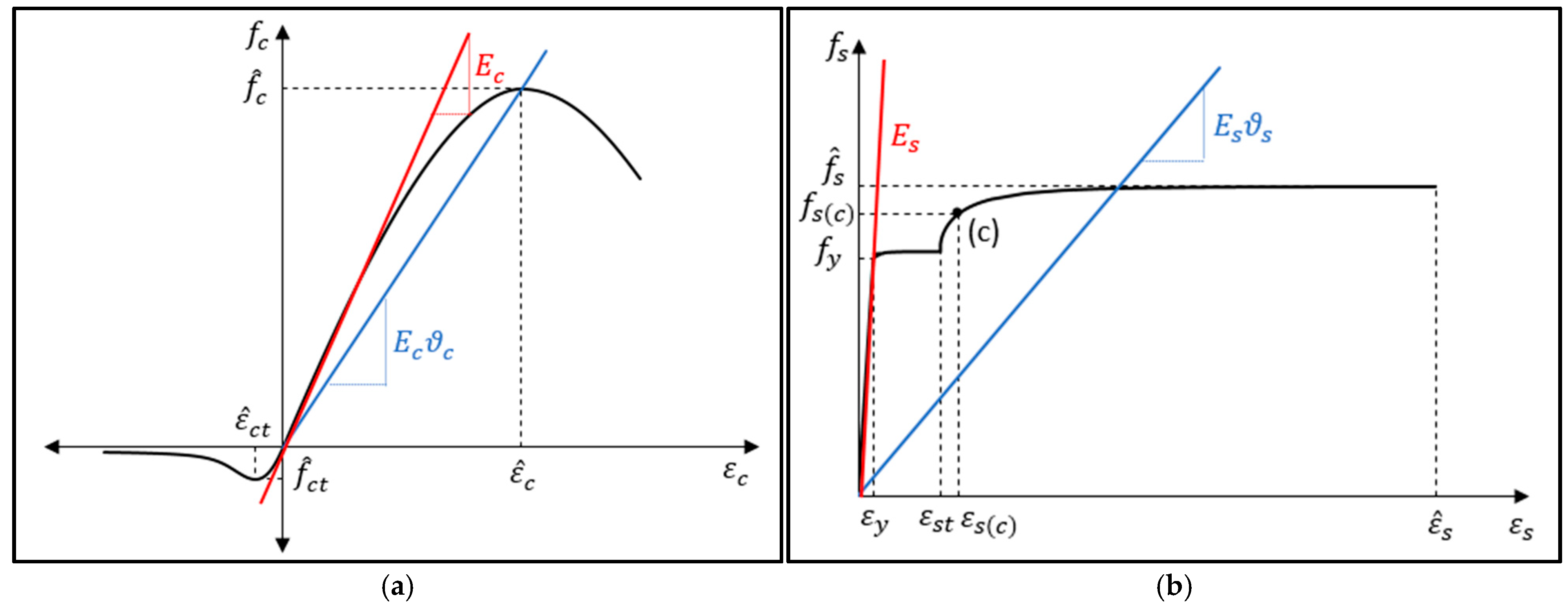
The constitutive model proposed by Karpenko et al. [37,38,39] is adopted in this study to represent the nonlinear stress–strain behavior of concrete and steel reinforcement, as illustrated in Figure 1. In addition to its theoretical formulation, this model has been previously evaluated and validated against experimental data and alternative constitutive relationships in earlier studies [40,41]. In this model, the material stress is expressed as:
σ m = ε m E m v m
where E m v m denotes the secant modulus of elasticity corresponding to the current stress–strain state. The coefficient v m is equal to unity in the linear-elastic range and takes values less than unity in the nonlinear portion of the stress–strain curve.
For the nonlinear regime, Karpenko et al. [37,38,39] derived the following quadratic expression for the coefficient v m :
v m 2 1 + e 2 m v o v ^ m 2 ε ~ m 2 v ^ m 2 1 σ ~ m , e l 2 v m 2 v ^ m ε ~ m v o v ^ m 2 v ^ m 1 σ ~ m , e l e 1 m 2 e 2 m σ ~ m , e l 1 σ ~ m , e l + v ^ m 2 v o v ^ m 2 1 + e 1 m σ ~ m , e l 1 σ ~ m , e l e 2 m σ ~ m , e l 2 1 σ ~ m , e l 2 = 0
with the following definitions (Figure 1):
v ^ m = σ ^ m ε ^ m E m ,     ε ~ m = ε m ε ^ m ,     σ ~ m , e l = σ m , e l σ ^ m ,     e 2 m = 1 e 1 m
where the subscript m denotes the material type. Here, σ ^ m and ε ^ m represent the ultimate stress and the corresponding strain of the material, respectively; E m is the initial modulus of elasticity; v ^ m is the value of v m at the ultimate stress; ε m is the current material strain; σ m , e l is the maximum elastic stress; and e 1 m ,   e 2 m , and v o are material-dependent parameters defined in detail by Karpenko et al. [37,38,39].
The value of v m is obtained by solving Equation (2) and selecting the larger of the two real roots. This procedure ensures a continuous and stable representation of the material nonlinearity throughout the loading process.
In contrast to concrete and steel, the tensile and compressive behavior of the GFRP reinforcement is assumed to be linearly elastic up to failure.
The adopted constitutive model enables a unified treatment of concrete cracking, post-cracking tension stiffening, and nonlinear compression behavior within the sectional analysis framework.

2.3. Force Vector–Strain Vector Model

In order to analyze structural concrete members represented as linear bar elements, a force vector–strain vector formulation using MATLAB is employed. This formulation is based on the concept of secant sectional stiffness and represents a modified version of the original methodology proposed by Oukaili [33].
In the present study, the proposed formulation extends the original sectional analysis framework to accommodate multiple cross-sectional geometries (rectangular and circular sections) and hybrid reinforcement systems, including steel bars, GFRP bars, and embedded GFRP I-sections within a unified computational scheme. In addition, the MATLAB implementation enables a more modular and extensible structure for stress–strain iteration procedures, allowing consistent treatment of heterogeneous reinforcement contributions under nonlinear sectional equilibrium conditions.
These extensions, together with the generalized treatment of reinforcement configurations as presented in Equations (4)–(12), constitute the main methodological advancement beyond the original FORTRAN-based model.
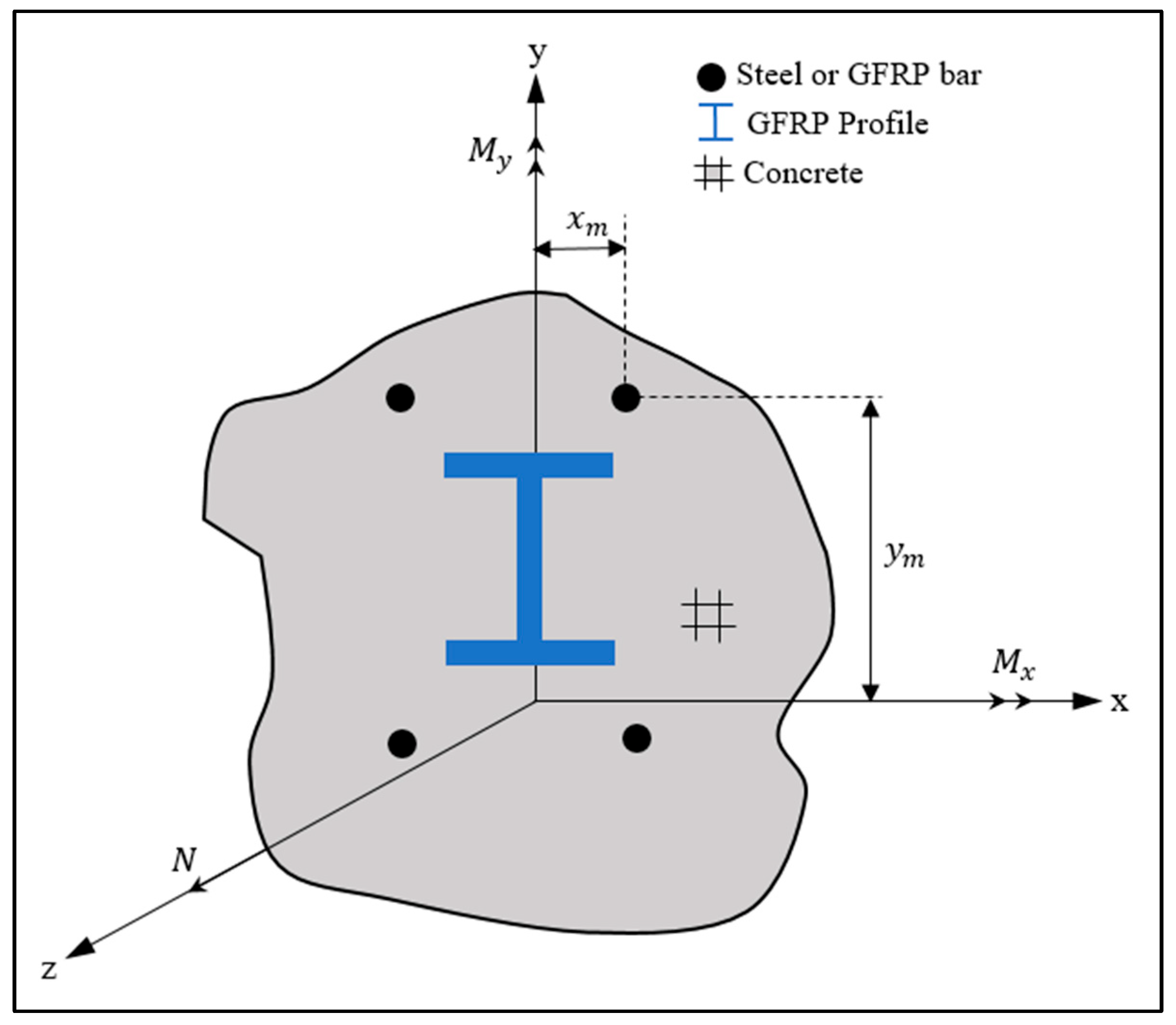
In this investigation, the principal modification introduced is that embedded GFRP profile sections are considered as independent sectional components within the cross-section of the beams (see Figure 2). The embedded GFRP profiles are discretized and included in the sectional equilibrium equations, in a similar manner to concrete fibers and steel reinforcing bars, enabling their axial stiffness to be included directly in the force–strain relationship.
Material nonlinearity of concrete and steel is captured through strain-dependent secant moduli, while the GFRP profiles are modeled as linear-elastic elements within their working strain range. Owing to the nonlinear behavior of the section, the solution of the governing equations requires an iterative numerical procedure.
By adopting the Karpenko constitutive model and enforcing equilibrium conditions at the cross-section level, the following expressions for the sectional axial force and bending moments can be obtained:
N = i = 1 i = r ε c i E c v c i A c i + j = 1 j = p ε s j E s v s j A s j + k = 1 k = q ε f k E f A f k
M x = i = 1 i = r ε c i E c v c i A c i y c i + j = 1 j = p ε s j E s v s j A s j y s j + k = 1 k = q ε f k E f A f k y f k
M y = i = 1 i = r ε c i E c v c i A c i x c i + j = 1 j = p ε s j E s v s j A s j x s j + k = 1 k = q ε f k E f A f k y f k
where N , M x , M y denote the axial force and bending moments about the x and y axes, respectively. Subscripts i ,   j ,   a n d   k refer to concrete fibers, steel reinforcement bars, and GFRP elements, respectively. The remaining symbols denote material strains ( ε ), moduli of elasticity ( E ), secant modulus factors ( v ), element areas ( A ), and distances of element centroids from the global reference axes ( x , y ). The parameters r , p , q represent the numbers of concrete, steel, and GFRP elements in the cross-section.
Based on the plane-sections assumption, the strain in each cross-sectional component is expressed in terms of the strain vector as
ε c i = ε o + κ x y c i + κ y x c i
ε s j = ε o + κ x y s j + κ y x s j
ε f k = ε o + K x y f k + K y x f k
where ε o is the axial strain at the reference axis, and κ x and κ y are the curvatures about the x and y axes, respectively.
Substituting Equations (7)–(9) into Equations (4)–(6) yields
N = i = 1 i = r ε o + κ x y c i + κ y x c i E c v c i A c i + j = 1 j = p ε o + κ x y s j + κ y x s j E s v s j A s j + k = 1 k = q ε o + κ x y f k + κ y x f k E f A f k
M x = i = 1 i = r ε o + κ x y c i + κ y x c i E c v c i A c i y c i + j = 1 j = p ε o + κ x y s j + κ y x s j E s v s j A s j y s j + k = 1 k = q ε o + κ x y f k + κ y x f k E f A f k y f k
M y = i = 1 i = r ε o + κ x   y c i + κ y   x c i E c   v c i   A c i   x c i + j = 1 j = p ε o + κ x   y s j + κ y   x s j E s   v s j   A s j x s j + k = 1 k = q ε o + κ x y f k + κ y x f k E f A f k x f k
By decomposing the above equations and arranging them in matrix form, the relationship between the force vector F , the strain vector ε ¯ , and the secant stiffness matrix C can be expressed as follows:
F = C ε ¯
or explicitly,
N M x M y = C 11 C 12 C 13 C 21 C 22 C 23 C 31 C 32 C 33 ε o κ x κ y
where the elements of the secant stiffness matrix are defined as
C 11 = i = 1 i = r E c v c i A c i + j = 1 j = p E s v s j A s j + k = 1 k = q E f A f k
C 12 = C 21 = i = 1 i = r E c v c i A c i y c i + j = 1 j = p E s v s j A s j y s j + k = 1 k = q E f A f k y f k
C 13 = C 31 = i = 1 i = r E c v c i A c i x c i + j = 1 j = p E s v s j A s j x s j + k = 1 k = q E f A f k x f k
C 22 = i = 1 i = r E c v c i A c i y c i 2 + j = 1 j = p E s v s j A s j y s j 2 + k = 1 k = q E f A f k y f k 2
C 23 = C 32 = i = 1 i = r E c v c i A c i y c i x c i + j = 1 j = p E s v s j A s j y s j x s j + k = 1 k = q E f A f k y f k x f k
C 33 = i = 1 i = r E c v c i A c i x c i 2 + j = 1 j = p E s v s j A s j x s j 2 + k = 1 k = q E f A f k x f k 2
Equation (14) is nonlinear due to the strain-dependent secant stiffness matrix and therefore requires an iterative solution. The strain vector can be obtained as
ε ¯ = C ε ¯ 1 F
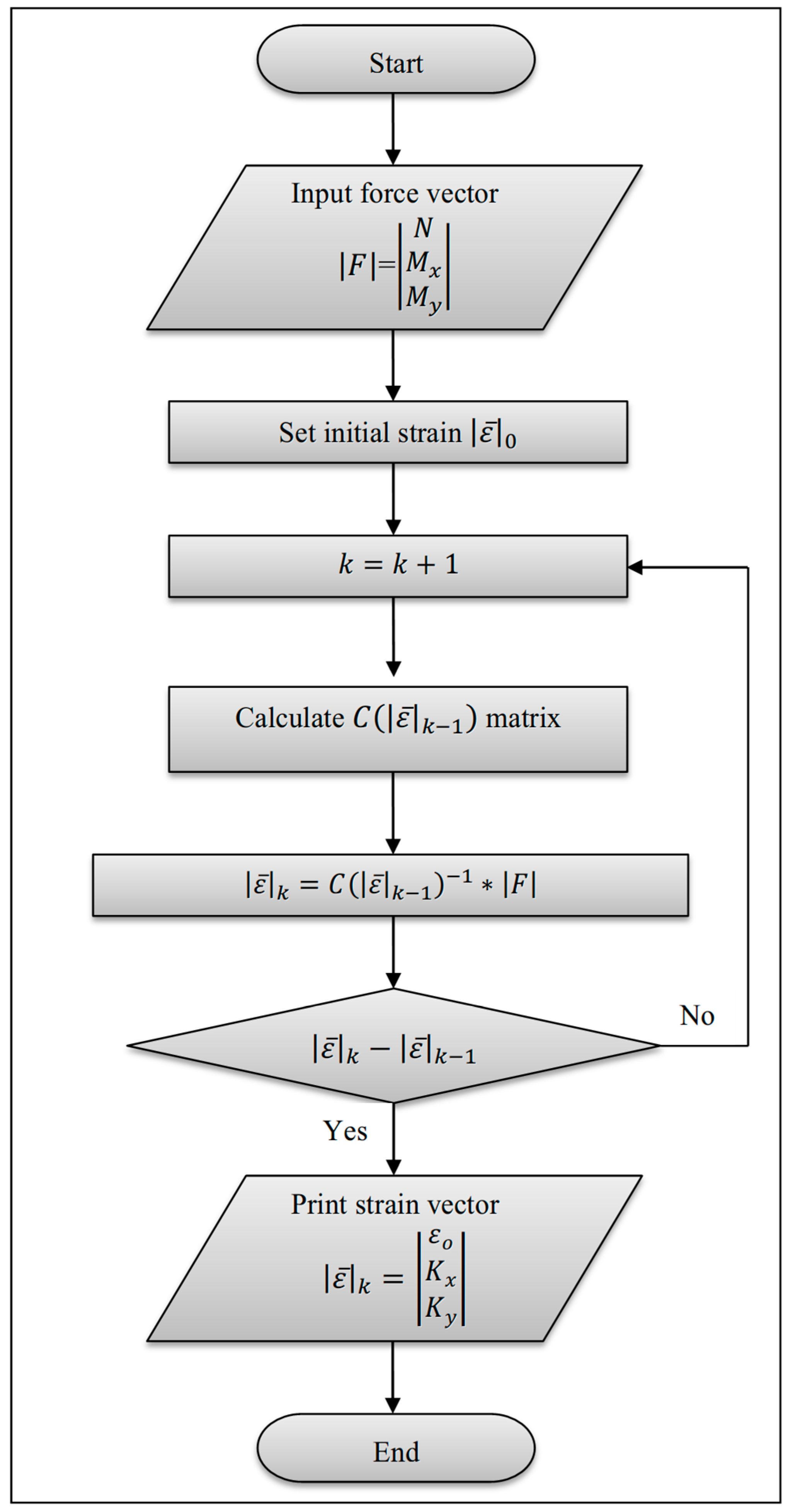
When performing the first iteration, n = 1 , to define the updated strain vector, an initial strain vector value is set to zero so that an initial evaluation of the secant stiffness matrix can be completed. From here on ( n > 1 ), the stiffness matrix is updated by using the strain vector from the previous iteration ( n 1 ) to create the following recursive formula:
ε ¯ n = C ε ¯ n 1 1 F
The iterative process is repeated until convergence of the strain vector is achieved according to the following criterion:
ε ¯ n ε ¯ n 1 < δ
where δ is a prescribed convergence tolerance. The flow chart of the iterative procedure is shown in Figure 3. Owing to the use of secant stiffness, the proposed procedure is straightforward to implement and provides stable and accurate numerical solutions for the nonlinear flexural response.
Additionally, based on a numerical model, the bisection method was employed to determine the ultimate load. In this method, the external load was applied incrementally, a series of iterations was performed with each increment to determine the strain in all materials (such as concrete or steel), and it was compared with the ultimate strain of the materials. If the strain results were less than the ultimate strain of the materials, the additional load increment was added, and the strain vectors were updated. Conversely, if the strain results were greater than the ultimate strain, the load decreased.
The iterative process is repeated until convergence of the force vector is achieved according to the following criterion:
F n F n 1 < δ
where F n is the external load vector of the present iteration, F n 1 is the external load vector of the previous iteration; δ is a prescribed convergence tolerance. It is worth mentioning that the same method was employed to determine the cracking load and yield load.
The numerical formulation can include longitudinal GFRP reinforcement bars in addition to conventional steel bars (Equations (7)–(12) and (15)–(20)). The GFRP bars can be either part of a hybrid reinforcement system (steel + GFRP) or they can be fully GFRP bars. For GFRP bars, their modulus of elasticity ( E f ), cross-sectional area ( A f ), coordinates x f , y f , and the elasticity coefficient ( ν f ) replace E s , A s , x s , y s , and ν s (where ν f = 1 due to linear-elastic behavior). The embedded GFRP pultruded profile is included in the cross-section of each model element, contributing to the calculation of sectional forces/moments/stiffness and ensuring strain compatibility with the surrounding concrete and longitudinal reinforcement bars. The model developed allows for the modeling of sections containing steel only, GFRP only, or hybrid longitudinal reinforcement bars, while also preserving the effects of the embedded GFRP profile in an identical manner.

2.4. Deflection of Structural Members

The deflection of structural concrete members is evaluated using the curvature-based numerical integration method, consistent with the recommendations of ACI 318-25 [42] and fib Model Code [43] for nonlinear structural analysis, discretizing the member along its effective span into a finite number of cross-sections. At each discretized location, sectional equilibrium is enforced to calculate the internal force vector, which is transformed using the suggested analysis model into sectional strain and curvature components through the nonlinear force–strain relationship of the composite concrete–reinforcement section. Finally, the deflection at a specified location is obtained by applying the unit load (virtual work) method by numerically integrating the sectional curvature and the corresponding bending moment induced by a unit load applied at that location along the member’s effective span, where bending about the y-axis contributes to deflection in the x-direction and vice versa, reflecting the standard curvature–displacement coupling in beam theory. The deflection components in the orthogonal directions are evaluated using the following expressions:
δ x z = l = 1 s κ y l m y l z
δ y z = l = 1 s κ x l m x l z
where δ x ( z ) , δ y ( z ) denote the deflections in the x and y directions at distance z from the member end, respectively. The subscript l refers to the member cross-section index, and s represents the total number of considered cross-sections along the member’s effective span. κ x l and κ y l are the sectional curvatures about the x and y axes, respectively, calculated according to the sectional analysis model proposed in this study. The terms m x l z , m y l z represent the bending moments at the ι t h cross-section resulting from a unit load applied at distance z from the member end in the y and x directions, respectively. The parameter represents the numerical integration step, defined as the spacing between subsequent considered cross-sections along the member’s effective span.
To ensure numerical convergence of the displacement response, a uniform discretization scheme was adopted along the member’s effective span, where a sufficient number of cross-sections were used. This approach keeps the results in line with recommendations for curvature-based integration methods in nonlinear reinforced concrete analysis.

3. Validation of the Numerical Model

The numerical model proposed in this study is verified through comparisons with a selection of experimental results available in the literature. The primary objective of this verification is to evaluate the capability of the model to accurately predict the ultimate flexural capacity, load–deflection response, and sectional behavior of reinforced concrete beams with embedded pultruded I-GFRP profiles. Additionally, the selected specimens from previous studies were those that demonstrated full bond interaction between the GFRP and concrete, with flexural failure identified as the governing failure mode, as reported by the respective researchers. Consequently, the number of comparison models was limited due to the difficulty of obtaining specimens that satisfy these specific conditions and assumptions.
Several experimental studies, selected based on their relevance to the present analysis, are considered: Hadi and Yuan [29], Ibrahim et al. [31], Mahmood et al. [44], Ahmed et al. [45], Salman and Allawi [46], and Bahlol and Al-Ahmed [47].
The test specimens consist of various parameters such as cross-section shape (i.e., rectangular or circular), longitudinal reinforcement material (i.e., steel bars, GFRP bars, or pultruded GFRP I-section), and loading pattern (i.e., three-point or four-point bending), as shown in the summary in Table 1 and Table 2, which show the various cross-sectional geometries, longitudinal reinforcement configurations and the material properties of the test specimens included in this verification testing.
The numerical verification is carried out by applying the developed MATLAB implementation of the secant stiffness-based sectional model to each experimental beam. The predicted responses are compared with the experimental data in terms of:
  • Ultimate flexural capacity, defined as the maximum load or moment attained prior to failure;
  • Load–midspan deflection response, including both pre-cracking and post-cracking stiffness characteristics;
  • Sectional stress and strain distribution, evaluated at critical loading stages.
In order to achieve a meaningful and reliable comparison as part of model verification, the experimental and numerical simulations will model the same material properties, cross-sectional dimensions and reinforcement layout. All pultruded GFRP profiles that were tested will be specifically modeled with respect to their location and shape; longitudinal reinforcement will be modeled based on whether it was steel-only, GFRP-only or a hybrid type. Results obtained through the use of this approach will allow for the evaluation of the predictive ability of the proposed numerical model under actual test conditions, which closely replicate the experimental study design.
To quantify the accuracy of the numerical predictions, the relative difference between the experimental ultimate load and deflection and those predicted was determined. The graphical representations of the load–deflection curves also demonstrate the model’s capability to replicate the overall flexural behavior (including a reduction in stiffness due to cracking and the contribution to flexural strength achieved from the inclusion of the embedded GFRP profile).
The present verification procedure successfully illustrates that the proposed sectional modeling is able to successfully reflect the nonlinear flexural performance of reinforced concrete beams containing embedded GFRP profiles, thereby supporting the subsequent discussions of the numerical results presented.
The model verification confirmed the accuracy of the numerical model that was utilized in this analysis. The forthcoming section provides a detailed discussion of the flexural responses that were predicted, how they can be influenced by embedded GFRP profiles and the various types of reinforcement configurations that were used in composite beams.

4. Results and Discussion

4.1. Load–Deflection Validation

The numerical and experimental results displayed in Table 3 quantitatively confirm that the sectional numerical predictive model provides an adequate prediction of the flexural behaviors of RC beams with embedded GFRP profiles. The ratio of numerically predicted ultimate moments divided by the ultimate moments measured experimentally ranges from 0.73 to 1.16, with an average of approximately 0.93, a standard deviation of approximately 0.15, and a coefficient of variation of approximately 16%. This represents an average percentage deviation of approximately 7%, which is acceptable for performing nonlinear sectional analyses of hybrid RC beams. Due to the wide variety of experimental data available in the literature, which includes a variety of experimental configurations, reinforcement layouts, material properties, and loading schemes, these statistical indicators provide evidence of generally accurate predictions, but in some cases, with a slight conservative tendency.
Specimens studied by Hadi and Yuan [29] displayed an experimental ultimate moment in the range of 113.57 kN.m to 138.36 kN.m versus a numerically predicted moment in the range of 112.70 kN.m to 135.57 kN.m; thus, the average deviation for the data was about 5%, whereas the highest deviation of 18.5% occurred with the S0.57M specimen.
The predicted ultimate moment values for the hybrid reinforcement beam types were slightly underestimated for type S0.57M and type F0.46M, whereas there was excellent agreement with actual values for type S0.57B and type F0.46B. These differences could likely be explained by idealized modeling assumptions including the perfect bonding hypothesis and homogeneous material properties, both of which affect the post-cracking behavior of beams with hybrid reinforcement through stiffness reductions and redistribution of strain.
Similar evidence that the numerical model slightly underestimated the ultimate flexural load of beams was observed and reported by Ibrahim et al. [31], Mahmood et al. [44], Salman and Allawi [46], and Ahmed et al. [45]. In contrast, the specimen tested by Bahlol and Al-Ahmed [47], which depended mainly on embedded pultruded GFRP profiles, demonstrated slight overestimation by the proposed numerical model. Therefore, this indicates that any overprediction of responses by the proposed model may be attributed to the absence of locally induced imperfection, premature cracking, or damage mechanisms that presented during the experimental test at the analyzed section but were not addressed in the sectional formulation of the proposed numerical model. This behavior is consistent with the linear-elastic assumption of GFRP reinforcement, which does not include stress redistributions due to local cracking, progressive damage, or possible local instability occurring at higher deformation modes.
Based on the test results reported by Ibrahim et al. [31] and Mahmood et al. [44], it can be concluded that the numerical model reasonably represents the cracking and yielding behavior; however, it underestimates the yielding and ultimate moments exhibited by the EGS-A specimen. The underestimation of the yielding and ultimate moments is mainly attributed to the idealized assumptions incorporated in the numerical model, such as the uniform material properties and the perfect bonding between components, thus limiting its ability to account for localized micro-cracking, redistribution of strain at the onset of yielding, and the post-cracking damage pattern observed experimentally but not explicitly present in the sectional analysis. The slight underestimation of cracking moments for the Bahlol and Al-Ahmed [47] specimens employing primarily embedded pultruded GFRP profiles and bars was also evidenced by the numerical model, which did not account for local variations in reinforcement or for inconsistencies (i.e., defects and irregularities) present in the tested specimens.
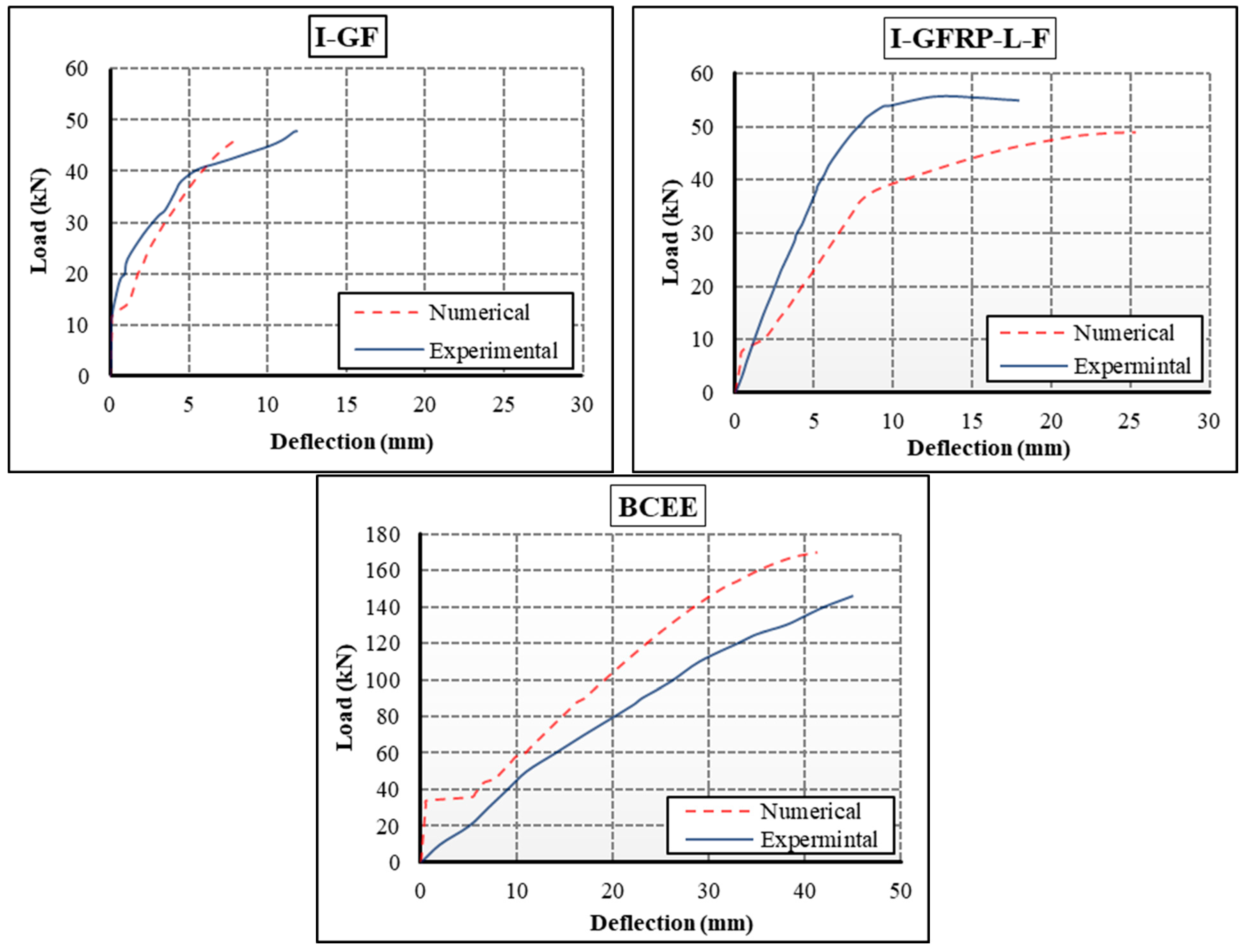
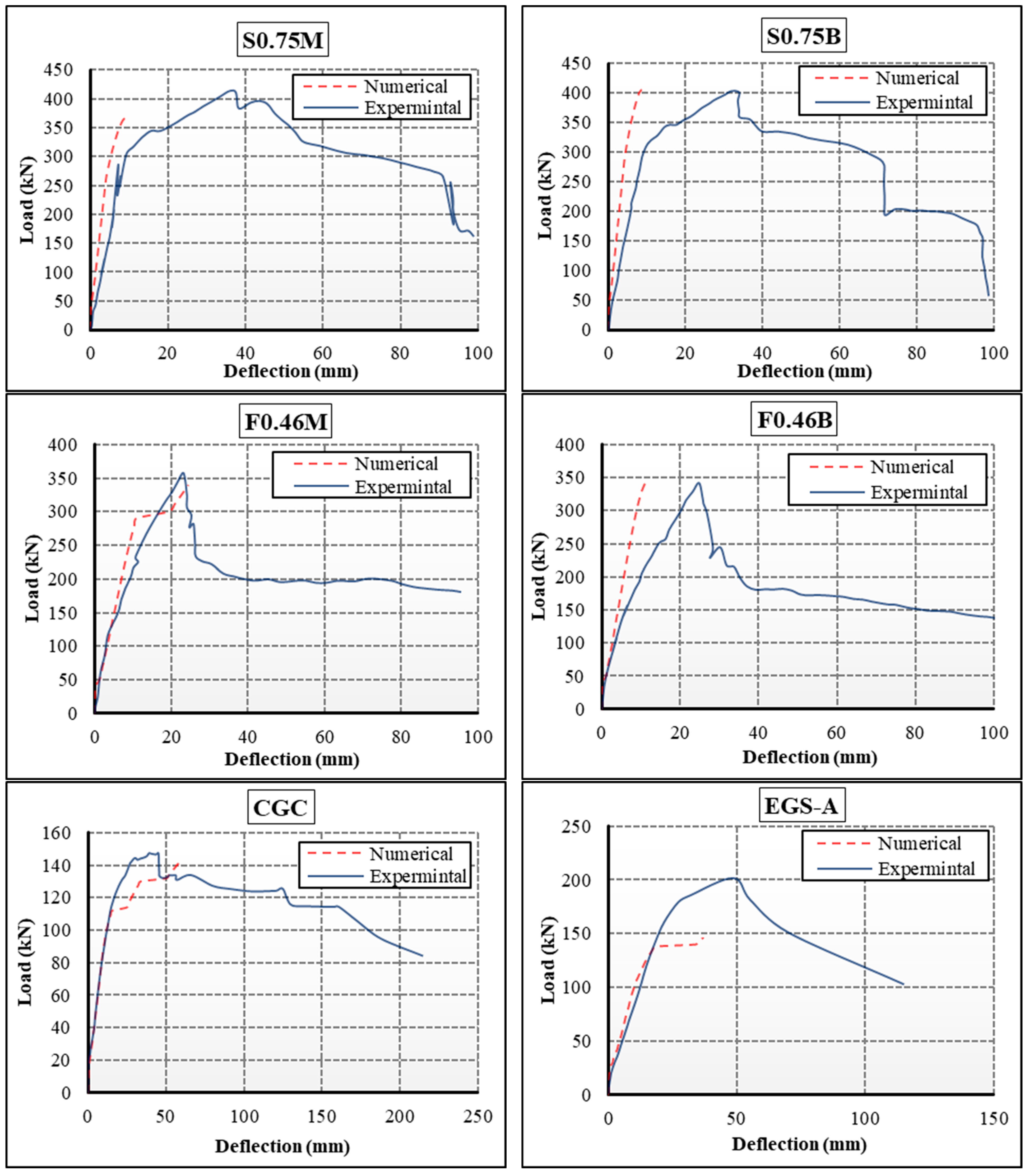
The comparison between experimental and numerical load–deflection responses demonstrates that the proposed sectional numerical model can reproduce the overall flexural behavior of reinforced concrete beams with embedded pultruded GFRP profiles with satisfactory accuracy. In general, the numerical predictions capture the transition from the uncracked elastic stage to the cracked regime and reasonably represent stiffness degradation up to ultimate load, although some differences in stiffness and deformation capacity are observed among individual specimens. The numerical curves generally display a stiffer response (i.e., smaller deflections at equivalent load levels) compared with experimental results, mainly due to the absence of micro-cracking effects, material heterogeneity, and localized damage mechanisms in the numerical model. Figure 4 shows that the load–deflection curves for both experimental and numerical models follow a similar trend, with close agreement in the elastic range and only minor deviations near the yielding and ultimate stages.
For the specimens reported by Hadi and Yuan [29], the numerical model predicts a slightly higher initial stiffness than observed experimentally. For example, in specimen F0.46B, the numerically predicted midspan deflection at ultimate load (11.22 mm) is substantially lower than the experimental value (24.10 mm).
This overestimation of values is based on unrealistic assumptions embedded in the sectional formulation, including perfect bonding conditions, with no consideration of bond–slip and distributed cracking effects. The proposed secant-stiffness sectional model relies on full bond action between concrete, steel or GFRP bars and embedded pultruded GFRP profiles, thereby indicating full strain compatibility and no slip at the interfaces between components. While this reduces computational complexity and achieves stable convergence, it excludes possible local phenomena such as debonding, micro-slip, or partial bonding, which may develop in hybrid concrete beams with GFRP bars or profiles. These behavioral effects may contribute to stiffness reduction, premature cracking, or a marginal increase in deflection compared to predictions. This assumption plays a significant role in the minor deviations noted between numerical and experimental results, mainly during the post-cracking response. Nonetheless, for the global response, the assumed perfect interface provides a satisfactory representation, and the model remains effective in predicting general patterns of stiffness reduction, crack propagation, and reinforcement interaction. Future investigations could integrate bond–slip mechanisms to better represent local interface behavior.
In contrast, the numerical and experimental results show strong correlations throughout the entire loading history for specimen CGC tested by Ibrahim et al. [31]. The numerical model predicts a maximum midspan deflection of 58.78 mm at ultimate load compared to an experimental value of 45.00 mm. This overestimation of the experimental results is primarily due to the idealized assumptions. Despite this, it can be concluded that the overall stiffness degradation and deformation progression of the specimen were accurately predicted, indicating that both the material constitutive models and compatibility assumptions provided reasonable representations.
Good correlation was achieved between the numerical load–deflection responses of the proposed model and the experimental data reported by Mahmood et al. [44] for specimen EGS-A. The numerical response is almost stiffer than the experimental response, resulting in an estimated midspan deflection of 37.01 mm compared to the experimental value of 48.68 mm. It is likely that the difference can be attributed to complex cracking patterns and localized damage, as well as to stiffness degradation processes that are not explicitly modeled using a section-wise approach.
The numerical models for specimens IG-F [45] and I-GFRP-L-F [46] with GFRP reinforcement and embedded GFRP profiles tend to predict somewhat more flexible behavior at serviceability levels than actual observed responses; however, the respective numerical predictions had generally good overall correlation with the experimental curves. This fact reflects the linear–elastic representation of material response adopted for GFRP reinforcement, which does not account for progressive damage or local instability mechanics, which may contribute to stiffness loss at increased levels of deformation.
For specimen BCEE, investigated experimentally by Bahlol and al-Ahmed [47], the numerical model demonstrates a stiffer behavior than the experimental response, with a greater ultimate deflection value. This overestimation may be attributed to premature cracking, possible experimental defects and irregularities, or failure mechanisms that were not represented in the idealized sectional formulation.
Although there were some discrepancies in stiffness and deformation capacity measurements—particularly at later stages of loading—the numerical model represents in a consistent manner the overall global shape of the load–deflection curves and accurately reproduces behavioral stages of the tested specimens. These findings indicate that the proposed sectional model based on initial and subsequent secant stiffness is a viable method for predicting the nonlinear flexural behavior of reinforced concrete beams with embedded GFRP profiles over a wide range of experimental conditions, including various reinforcement configurations.
It should be noted, however, that the numerical formulation assumes a perfect bond between concrete and internal reinforcement, including steel bars, GFRP bars, and the embedded GFRP profile. This assumption represents a simplification of actual behavior, as bond–slip effects, interface degradation, and localized debonding may develop under increasing load, particularly after cracking. In practice, such mechanisms can contribute to additional stiffness degradation and increased deflections, which are not explicitly captured in the present sectional approach. Nevertheless, for the purpose of predicting the global flexural response, the perfect bond assumption provides a reasonable approximation while maintaining computational efficiency.

4.2. Numerical Stresses of Concrete and Reinforcement

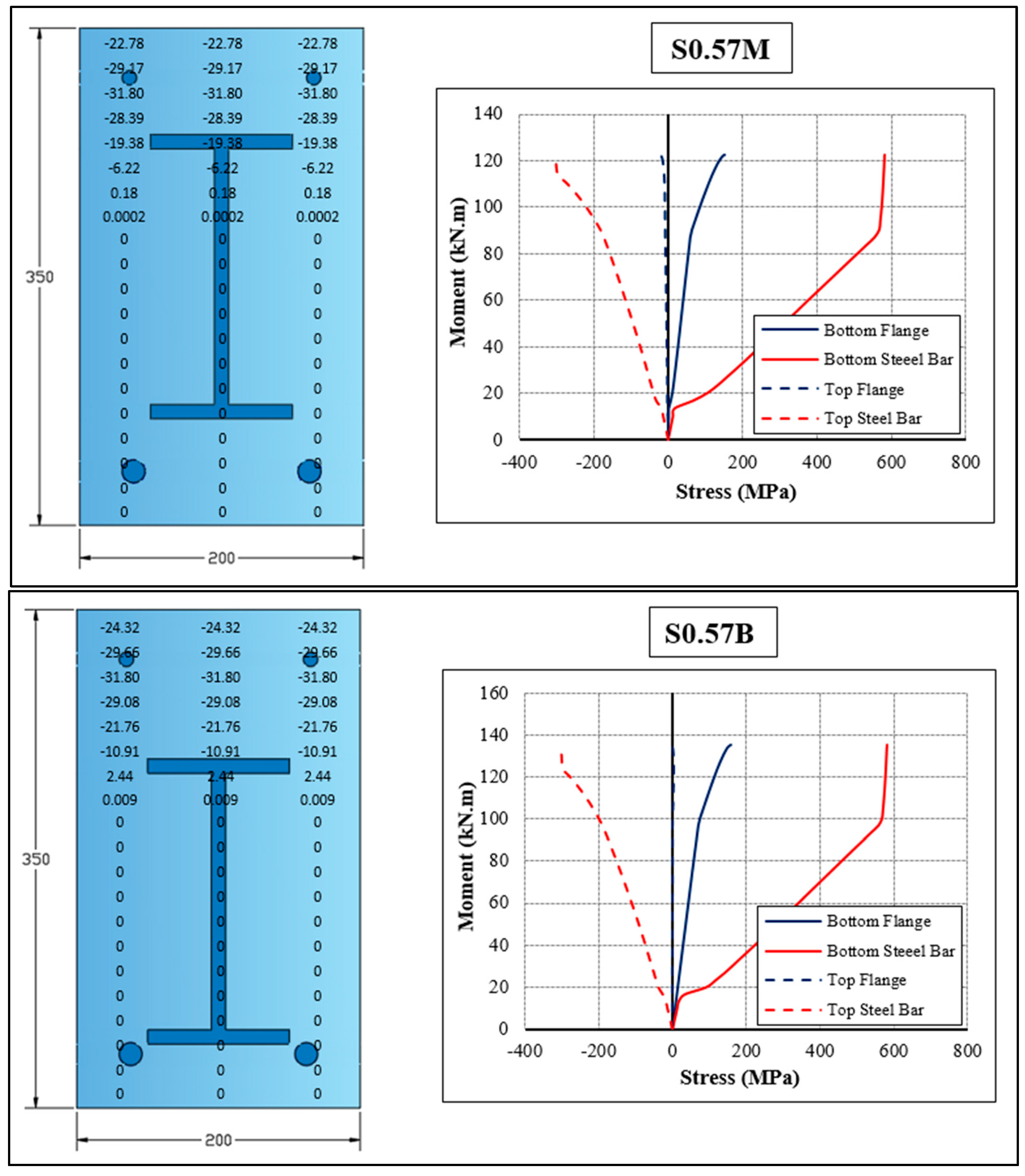
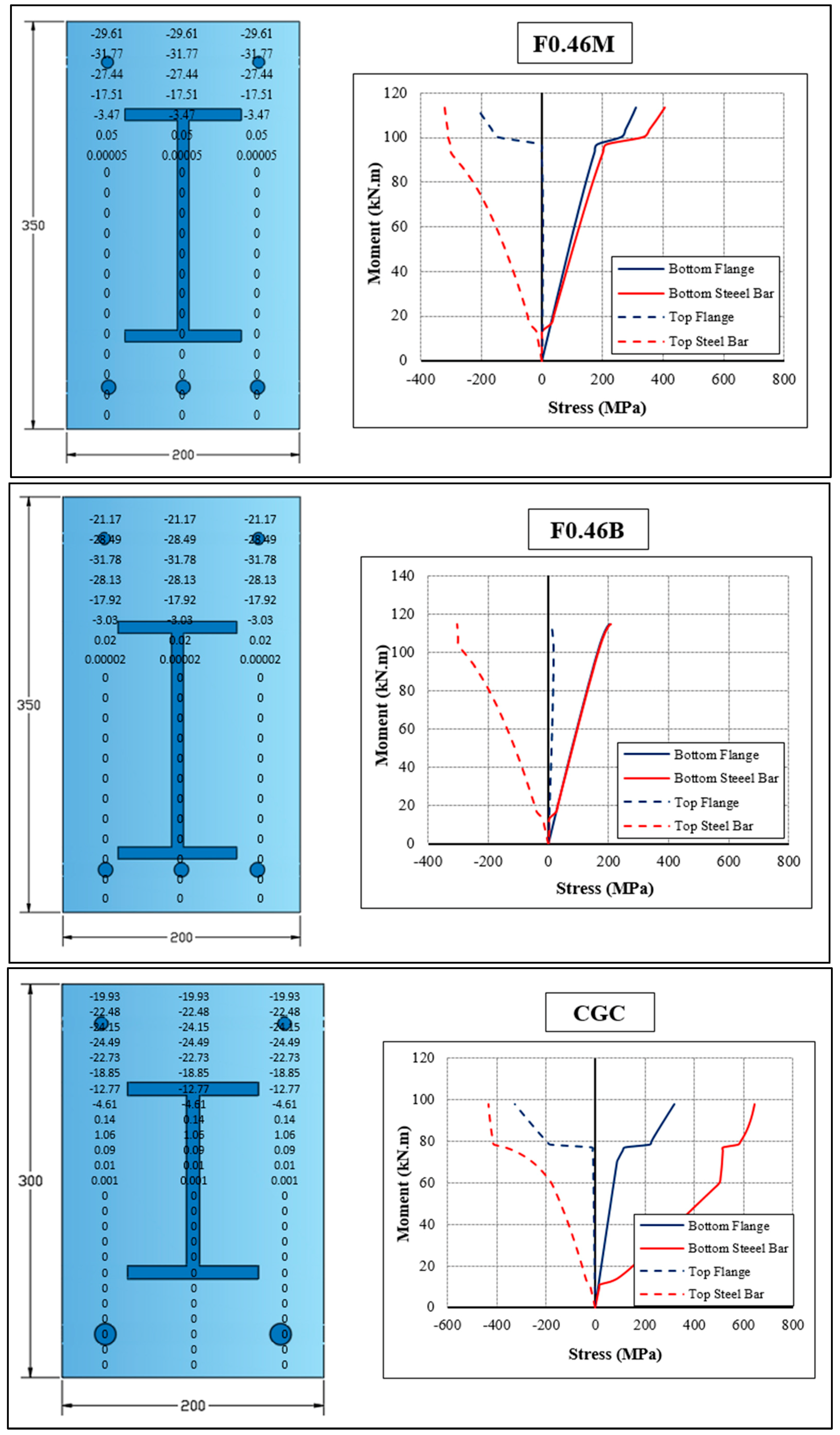
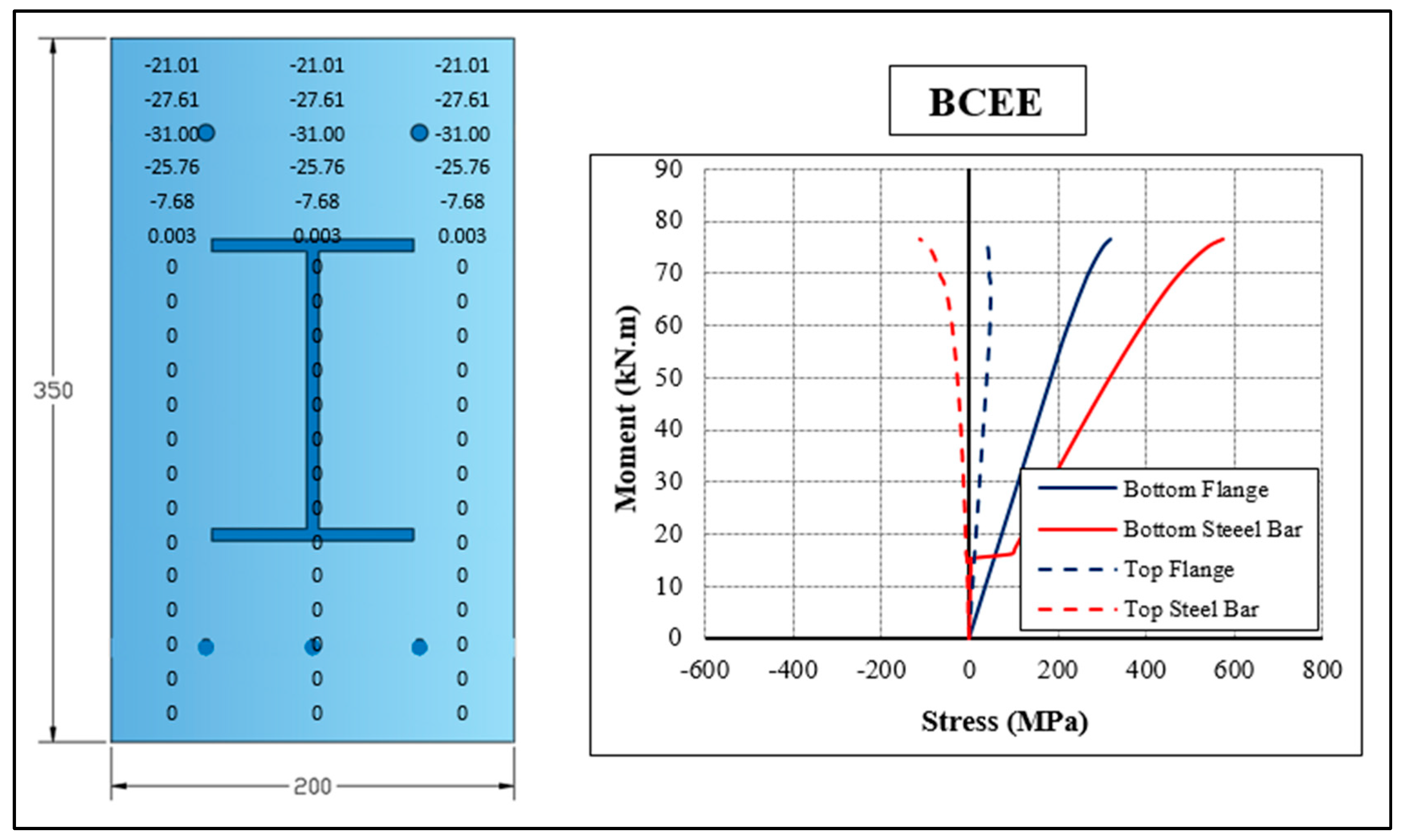
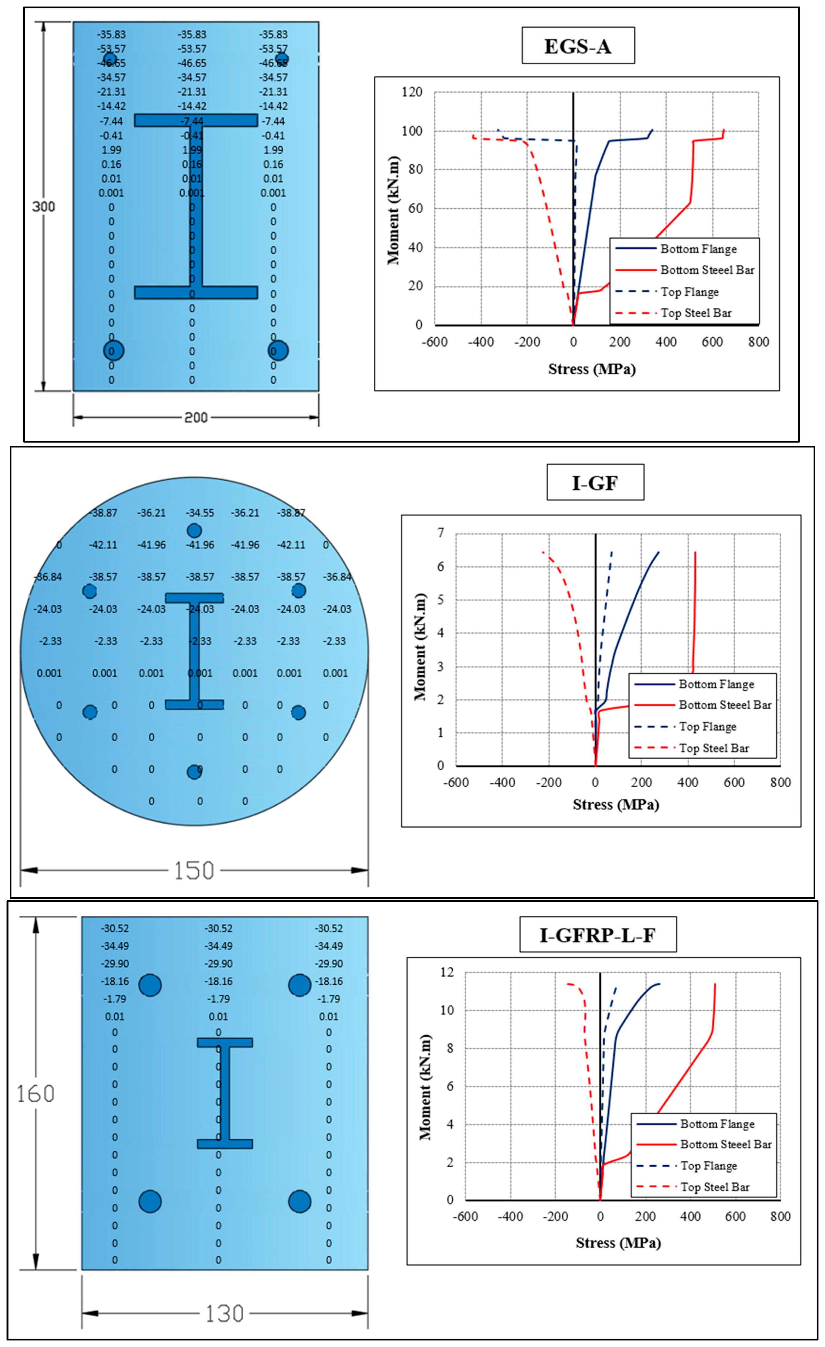
The proposed numerical methodology employed in this study is capable of predicting the stress response of concrete and all types of reinforcement (steel bar and I-GFRP profiles) at all loading levels. Figure 5 demonstrates the stress distribution in each concrete cell across all cross-sections at the failure stage, as well as the complete stress response of the tension and compression reinforcement throughout the loading history up to failure. As shown in the Figure 5, the stresses generated in the bottom flange of the I-GFRP profile are lower than those developed in both types of tension reinforcement (steel bars or GFRP bars) for all investigated specimens, except for the I-GF beam. In addition, the concrete stresses reached approximately the designed compressive strength for all specimens.

4.3. Parametric Analysis

Using the proposed numerical model, the ultimate flexural capacity and corresponding deflection of composite beams incorporating embedded GFRP profiles with either mild steel or GFRP bars can be evaluated. For the parametric analysis, the composite beam (CGC) tested by Ibrahim et al. [31] was selected as the reference specimen. This beam had a cross-section of 200 × 300 mm, with an embedded GFRP profile placed at the centroidal axis and two Ø16 mm mild steel bars in the tension zone. Based on this reference configuration, the effects of key parameters—including reinforcement ratio (0.731% and 1.097%), type of reinforcement (steel or GFRP bars), position of the GFRP profile (offsets of 15 mm, 30 mm and 40 mm from the center), concrete compressive strength ( f c ) (from 20 to 40 MPa), and the rotation of the I-GFRP profile (rotated by 90° in three different configurations)—are investigated and discussed in the following sections. These ranges of parameters were selected to ensure practical relevance and to maintain consistency with realistic structural configurations encountered in engineering applications.

4.3.1. Effect of Longitudinal Reinforcement Ratio and Type

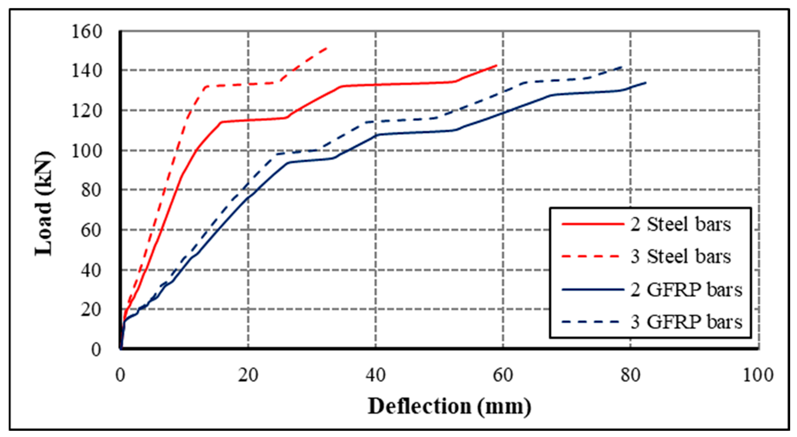
In this study, in the second case, the two Ø16 mm mild steel bars with a 0.731% reinforcement ratio of the composite CGC (the first case) were replaced by three Ø16 mm mild steel bars with a 1.097% reinforcement ratio. In addition, in the third and fourth cases, the steel tension reinforcement was replaced by GFRP bars while keeping the same reinforcement ratios of 0.731% and 1.097%, respectively.
As shown in Figure 6, increasing the longitudinal reinforcement ratio led to an increase in load capacity and a reduction in midspan deflection for both steel- and GFRP-reinforced beams due to greater ability to resist tensile stress developed after concrete cracking. Since concrete possesses limited tensile strength, the reinforcement becomes the primary load-resisting component in the tension zone once cracking occurs.
Conversely, when the reinforcement type was changed from steel to GFRP at the same reinforcement ratio, a reduction in load capacity accompanied by an increase in midspan deflection was observed. This behavior is attributed to the lower modulus of elasticity of GFRP compared with that of steel. At the ultimate stage, increasing the tension reinforcement from two to three bars resulted in an increase in ultimate load of 7.07% and 6.74% for steel and GFRP reinforcement, respectively, while the corresponding ultimate deflection decreased by 43.94% and 2.97%.
Moreover, replacing steel reinforcement with GFRP bars led to a reduction in ultimate load of up to 5.82% and 6.11% for beams reinforced with two and three bars, respectively. In contrast, the maximum midspan deflection increased by 39.51% and 141.45% for the same cases.
Overall, Figure 6 indicates that the longitudinal reinforcement ratio is the most influential parameter governing both load capacity and deflection of composite beams under static loading.

4.3.2. Effect of I-GFRP Profile Position

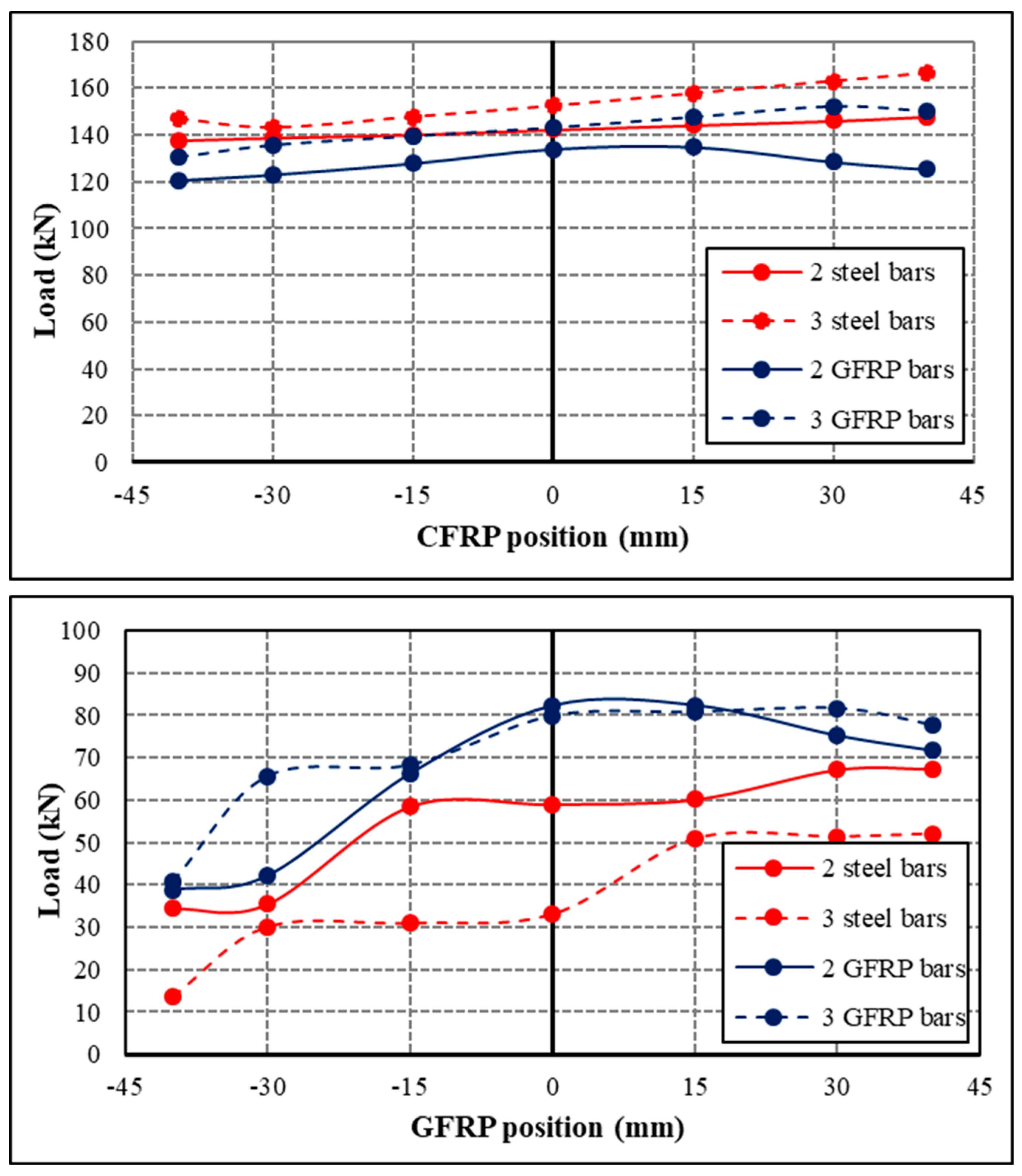
In this study, the embedded I-GFRP profile was positioned at four different locations within the cross-section: three positions below the centroidal axis and three above it. Vertical offsets of 15 mm, 30 mm and 40 mm from the center of the cross-section were considered to represent these locations. Figure 7 illustrates the influence of the I-GFRP profile position on the load and deflection response of the composite beam.
As shown in Figure 7, relocating the I-GFRP profile away from the centroidal axis—either upward or downward—significantly affects both the ultimate load and deformation capacity of the beam. The direction and magnitude of these changes depend on the type and ratio of longitudinal reinforcement as well as the distance of the I-GFRP profile from the center.
The numerical results indicated that shifting the I-GFRP profile downward by 40 mm to align it with the longitudinal steel reinforcement resulted in a decrease of 3.16% and 3.55% in the ultimate load capacity of beams reinforced with two and three steel tension bars, respectively. The corresponding reductions in the ultimate deflection were 41.61% and 58.69%. Similarly, beams reinforced with two and three GFRP tension bars exhibited decreases in ultimate load of 10.03% and 8.89%, respectively, accompanied by reductions in ultimate deflection of 52.89% and 49.05%. These trends confirm the experimental findings documented by Hadi and Yuan [29].
In contrast, the ultimate load increased by 3.93% and 9.15% for beams reinforced with two and three steel tension bars, respectively, when the I-GFRP profile was relocated 40 mm upward from the center of the cross-section. The corresponding increases in ultimate deflection were 14.11% and 57.39%. The ultimate load for the beam reinforced with three GFRP tension bars increased by 4.98% when the I-GFRP profile was moved from the center of the cross-section to 40 mm above, while the ultimate deflection decreased by 2.68%. Conversely, the beam reinforced with two GFRP tension bars experienced reductions of approximately 6.53% in ultimate load and 12.95% in ultimate deflection.
The position of the I-GFRP profile at an optimal depth increases the internal lever arm between the tension and compression force, thereby enhancing the flexural resistance of the beam. However, placing the I-GFRP profile away from the critical tension region reduces its structural contribution and beam capacity.
In summary, the results suggest that the placement of the embedded I-GFRP profile plays an important role in the flexural behavior of composite beams, yet it is strongly influenced by the type and ratio of longitudinal reinforcement, highlighting the need to account for these variables concurrently in the analysis and design of such beams.

4.3.3. Effect of Concrete Compressive Strength

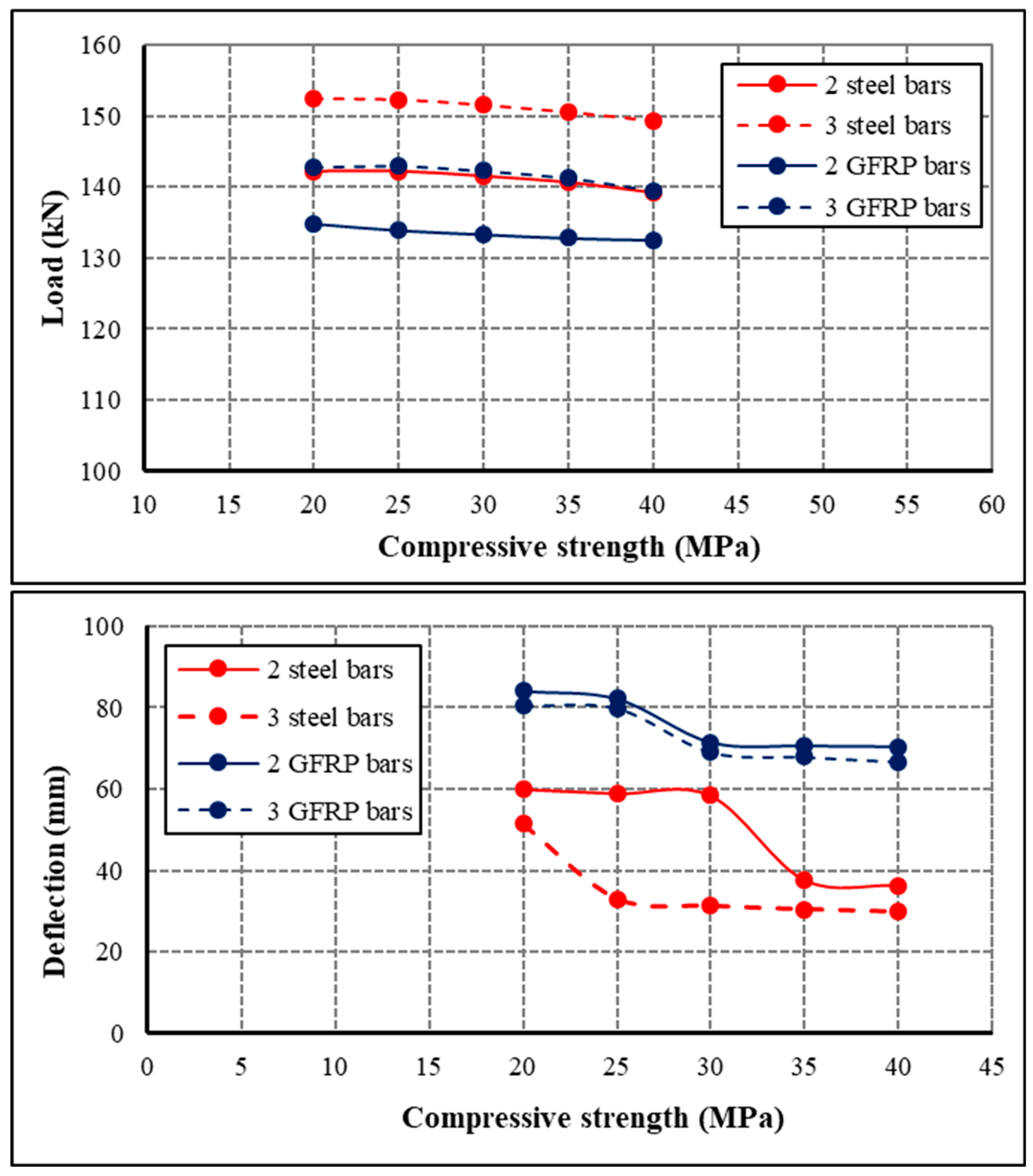
Using five concrete compressive strength levels (20, 25, 30, 35, and 40 MPa), the influence of concrete compressive strength on the bending behavior of composite beams incorporating embedded GFRP profiles was evaluated. The analysis included beams reinforced with two and three longitudinal tension bars of either steel or GFRP while maintaining identical geometric configurations and reinforcement details across all specimens.
As indicated in Figure 8, increasing the concrete compressive strength from 20 to 40 MPa resulted in a marginal decrease in ultimate load for all composite beams; however, it also resulted in a significant decrease in midspan deflection. The maximum decreases in ultimate load were 2.13%, 2.03%, 1.76%, and 2.32% for composite beams reinforced with two steel, three steel, two GFRP, and three GFRP tension bars. On the contrary, the corresponding decreases in ultimate midspan deflection were substantially greater, reaching 39.63%, 42.06%, 16.46%, and 17.03%.
The observed behavior can be explained by the fact that the composite beams are tension-controlled, with failure occurring primarily due to the response of the longitudinal reinforcement and its interaction with the embedded GFRP profile rather than concrete crushing. With an increase in concrete compressive strength, the compression zone becomes more concentrated, resulting in a reduction in its depth and a slight increase in the internal lever arm. Nevertheless, since the tensile force in the steel or GFRP reinforcement is controlled by its mechanical properties and strain compatibility, it does not increase proportionally with concrete compressive strength. As a result, the ultimate flexural capacity exhibits minimal variation or a marginal decrease.
On the other hand, the increase in concrete compressive strength significantly enhances the sectional stiffness, delays crack propagation, and limits strain development, resulting in a substantial reduction in deflection at advanced loading stages. Furthermore, for a given concrete strength, increasing the longitudinal reinforcement ratio consistently improves the ultimate load and reduces the midspan deflection for both steel- and GFRP-reinforced composite beams, as illustrated in Figure 8.
Overall, the results indicate that, for composite beams with embedded GFRP profiles, concrete compressive strength plays a secondary role in determining ultimate flexural capacity, while it has a dominant influence on stiffness and deformation behavior.

4.3.4. Influence of I-GFRP Profile Rotation on Ultimate Load and Deflection

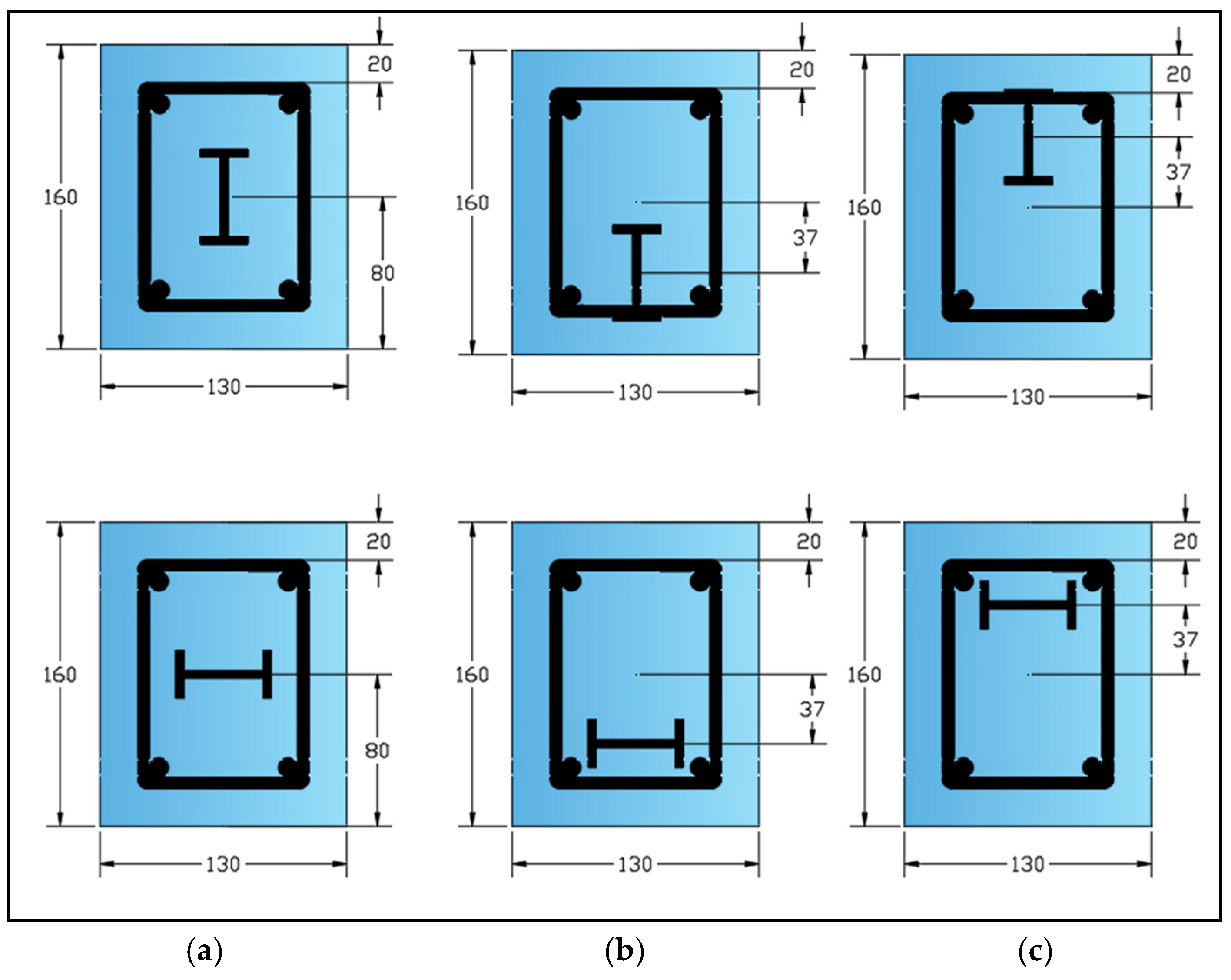
In this study, a numerical analysis was performed on the I-GFRP-L-F beam to investigate the influence of rotating the I-GFRP profile by 90 ° in three different configurations (see Figure 9). In the first configuration, the I-GFRP profile was positioned at the centroid of the cross-section, such that the centroids of the concrete cross-section and the I-GFRP profile coincided. In the second configuration, the I-GFRP profile was positioned within the tension zone at the same level as the longitudinal tension reinforcement. Finally, in the third configuration, the I-GFRP profile was positioned within the compression zone at the same level as the longitudinal compression reinforcement. The effects on ultimate load, deflection, and ductility are analyzed using the proposed numerical methodology.
The I-GFRP-L-F beam was selected for this investigation because it is the only specimen among the beams under consideration that incorporates a second geometric dimension capable of accommodating the I-GFRP profile.
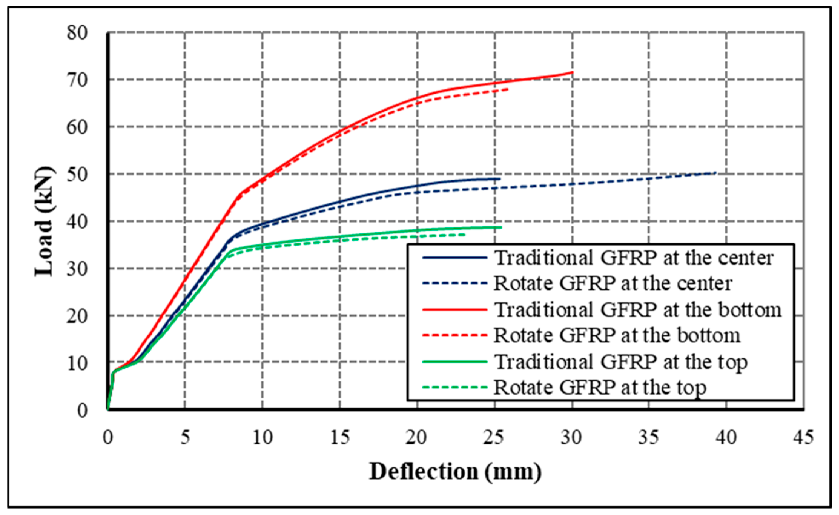
Compared with the traditional embedding of the I-GFRP profile at the center, the results presented in Figure 10 indicate that rotating the I-GFRP profile to the centroid of the cross-section leads to an increase of 2.75% in ultimate load and a 54.85% increase in ultimate deflection.
When the I-GFRP profile is rotated within the tension zone of the beam, the beam exhibits an increase in ultimate load of 39.13% and a marginal increase in ultimate deflection of only 2.16%. Conversely, when the I-GFRP profile is rotated within the compressive zone of the section, the beam shows an ultimate load reduction of 24.23% and an ultimate deflection reduction of 8.08%. The redistribution of internal stresses in the I-GFRP profile contributes to this behavior: when the I-GFRP profile is located at the centroid, greater deformation occurs before yielding of the reinforcement, enhancing ductility. Conversely, positioning the profile within the tension zone increases the effective tensile stiffness of the beam, allowing for a higher ultimate load while limiting further deflection beyond the ultimate load.
Moreover, the numerical results show that rotating the I-GFRP profile within the tension and compression zones of the beam’s cross-section, at the same level as the reinforcement, reduces the ultimate load by approximately 13.62% and 8.25%, respectively, compared with the traditional embedding of the profile. The corresponding reductions in ultimate deflection are 5.1% for the tension zone and 4.36% for the compression zone.
Overall, rotating the I-GFRP profile to the centroid enhances beam ductility, while rotation within the tension zone primarily improves ultimate load capacity.

5. Conclusions

The present study was conducted to evaluate the proposed numerical model to predict the flexural behavior of hybrid RC beams with embedded GFRP profiles under monotonic static loading with different cross-sections, such as rectangular and circular. The main conclusions are as follows:
  • The comparison between experimental and numerical results showed good agreement in predicting the structural response of the tested beams. The average ratio of the numerical ultimate moment to the experimental ultimate moment was approximately 0.93, with a standard deviation of 0.15 and a coefficient of variation of 16%.
  • The load–deflection behavior and the key stages of the structural response, including cracking, yielding, and ultimate capacity, were accurately captured by the proposed numerical model.
  • Minor discrepancies between the numerical model and the actual behavior were primarily attributed to idealized material properties and modeling assumptions, including the perfect bond between concrete and GFRP and the absence of localized imperfections.
  • The results verify that the numerical model proposed in this study is a reliable and efficient tool for predicting strength, stiffness, and deformation characteristics of hybrid RC beams with embedded GFRP sections under flexural loading.
  • The successful predictive capacity of this model supports its use in future parametric studies and design applications, as well as in structural analysis and optimization.
  • The most significant numerical parameter influencing the load and deflection of the hybrid beam under static loading is the longitudinal reinforcement ratio. Increasing the tension reinforcement from two to three bars resulted in an increase in the ultimate load of 7.07% and 6.74% for steel and GFRP reinforcement, respectively. Meanwhile, the corresponding ultimate deflection decreased by 43.94% and 2.97%, respectively.
  • The ultimate load of the hybrid beam decreased when the I-GFRP profile was positioned 15, 30, and 40 mm below the centroid of the cross-section and increased when it was placed above the centroid. The maximum reduction in numerical ultimate load was 10.03% for beams reinforced with two GFRP tension bars, while the maximum increase was 9.15% for beams reinforced with three steel tension bars. These results were recorded when the I-GFRP profile was shifted downward and upward by 40 mm, respectively, to align with the longitudinal steel reinforcement.
  • The hybrid beam with two or three steel or GFRP bars reinforcement experienced a slight reduction in ultimate load as the concrete compressive strength increased, while a significant decrease in deflection was observed. Therefore, the results indicate that concrete compressive strength plays a secondary role in determining the ultimate flexural capacity.
  • The numerical parametric results indicated that rotating the I-GFRP profile by 90 ° about the centroid enhances the beam ductility, whereas rotation within the tension zone primarily improves the ultimate load capacity.

Author Contributions

Conceptualization, N.O., A.A. (Abbas Allawi) and A.A. (Amjad Albayati); methodology, N.O., A.A.A., A.A. (Abbas Allawi) and A.A.-R.; software, A.A.-R.; validation, A.A.A., A.A.-R. and T.H.I.; formal analysis, A.A.-R.; investigation, A.A.A., A.A.-R., E.M.M. and T.H.I.; resources, N.O., A.A. (Abbas Allawi), G.W., and A.A.A.; data curation, A.A.A., A.A.-R. and E.M.M.; writing—original draft preparation, A.A.A. and T.H.I.; writing—review and editing, N.O., A.A. (Abbas Allawi) and G.W.; visualization, N.O., A.A. and A.A. (Amjad Albayati); supervision, N.O., A.A. (Abbas Allawi), A.A. (Amjad Albayati) and G.W. All authors have read and agreed to the published version of the manuscript.

Funding

This research received no external funding.

Data Availability Statement

Data are contained within the article.

Conflicts of Interest

The authors declare no conflicts of interest.

References

  1. Nunes, F.; Correia, J.R.; Silvestre, N. Structural behavior of hybrid FRP pultruded beams: Experimental, numerical and analytical studies. Thin-Walled Struct. 2016, 106, 201–217. [Google Scholar] [CrossRef]
  2. Yuksel, O.; Sandberg, M.; Baran, I.; Ersoy, N.; Hattel, J.H.; Akkerman, R. Material characterization of a pultrusion specific and highly reactive polyurethane resin system: Elastic modulus, rheology, and reaction kinetics. Compos. Part B Eng. 2021, 207, 108543. [Google Scholar] [CrossRef]
  3. Gemi, L.; Morkavuk, S.; Köklü, U.; Gemi, D.S. An experimental study on the effects of various drill types on drilling performance of GFRP composite pipes and damage formation. Compos. Part B Eng. 2019, 172, 186–194. [Google Scholar] [CrossRef]
  4. Morkavuk, S.; Köklü, U.; Bağcı, M.; Gemi, L. Cryogenic machining of carbon fiber reinforced plastic (CFRP) composites and the effects of cryogenic treatment on tensile properties: A comparative study. Compos. Part B Eng. 2018, 147, 1–11. [Google Scholar] [CrossRef]
  5. Lobo, P.S.; Faustino, P.; Jesus, M.; Marreiros, R. Design model of concrete for circular columns confined with AFRP. Compos. Struct. 2018, 200, 69–78. [Google Scholar] [CrossRef]
  6. Satasivam, S.; Bai, Y.; Zhao, X.L. Adhesively bonded modular GFRP web–flange sandwich for building floor construction. Compos. Struct. 2014, 111, 381–392. [Google Scholar] [CrossRef]
  7. Correia, J.R.; Branco, F.A.; Ferreira, J.G. Flexural behaviour of GFRP–concrete hybrid beams with interconnection slip. Compos. Struct. 2007, 77, 66–78. [Google Scholar] [CrossRef]
  8. Correia, J.R.; Branco, F.A.; Ferreira, J.G. Flexural behaviour of multi-span GFRP-concrete hybrid beams. Eng. Struct. 2009, 31, 1369–1381. [Google Scholar] [CrossRef]
  9. Aydın, F.; Sarıbıyık, A.; Sarıbıyık, M.; İpek, M. Experimental Study of Flexural Performance of Reinforced Concrete Beams and Hybrid Beams. Acta Phys. Pol. A 2018, 134. [Google Scholar] [CrossRef]
  10. Saribiyik, M.; Gosling, P.D. Experimental study of a bonded plastic fiber reinforced polymer connector assembly. J. Compos. Constr. 2004, 8, 549–559. [Google Scholar] [CrossRef]
  11. Madenci, E.; Özkılıç, Y.O.; Gemi, L. Buckling and free vibration analyses of pultruded GFRP laminated composites: Experimental, numerical and analytical investigations. Compos. Struct. 2020, 254, 112806. [Google Scholar] [CrossRef]
  12. Fernandes, L.A.; Gonilha, J.; Correia, J.R.; Silvestre, N.; Nunes, F. Web-crippling of GFRP pultruded profiles. Part 1: Experimental study. Compos. Struct. 2015, 120, 565–577. [Google Scholar] [CrossRef]
  13. Belabed, Y.; Kerboua, B.; Tarfaoui, M. New optimized numerical solution of interfacial stresses in steel strengthened structures with CFRP. Adv. Civ. Eng. Mater. 2019, 8, 117–133. [Google Scholar] [CrossRef]
  14. Tarfaoui, M.; El Moumen, A.; Boehle, M.; Shah, O.; Lafdi, K. Self-heating and deicing epoxy/glass fiber-based carbon nanotubes buckypaper composite. J. Mater. Sci. 2019, 54, 1351–1362. [Google Scholar] [CrossRef]
  15. Koaik, A.; Bel, S.; Jurkiewiez, B. Experimental tests and analytical model of concrete-GFRP hybrid beams under flexure. Compos. Struct. 2017, 180, 192–210. [Google Scholar] [CrossRef]
  16. Belarbi, A.; Acun, B. FRP systems in shear strengthening of reinforced concrete structures. Procedia Eng. 2013, 57, 2–8. [Google Scholar] [CrossRef]
  17. Saribiyik, A.; Abodan, B.; Balci, M.T. Experimental study on shear strengthening of RC beams with basalt FRP strips using different wrapping methods. Eng. Sci. Technol. Int. J. 2021, 24, 192–204. [Google Scholar] [CrossRef]
  18. Belabed, Y.; Kerboua, B.; Tarfaoui, M. New design for reducing interfacial stresses of reinforced structures with FRP plates. Int. J. Build. Pathol. Adapt. 2019, 37, 196–207. [Google Scholar] [CrossRef]
  19. Nachtane, M.; Tarfaoui, M.; Sassi, S.; El Moumen, A.; Saifaoui, D. An investigation of hygrothermal aging effects on high-strain-rate behaviour of adhesively bonded composite joints. Compos. Part B Eng. 2019, 172, 111–120. [Google Scholar] [CrossRef]
  20. Ezzine, M.C.; Madani, K.; Tarfaou, M.; Touzain, S.; Mallarino, S. Comparative study of the resistance of bonded, riveted and hybrid assemblies; Experimental and numerical analyses. Struct. Eng. Mech. Int. J. 2019, 70, 467–477. [Google Scholar]
  21. Wang, C.; Lu, Y.; Ma, Z. Quantitative characterization of interfacial enhancement in microfiber-reinforced recycled cementitious composites after carbonation using nanoindentation combined with 4D CT. Cem. Concr. Res. 2026, 201, 108115. [Google Scholar] [CrossRef]
  22. Gemi, L.; Madenci, E.; Özkılıç, Y.O. Experimental, analytical and numerical investigation of pultruded GFRP composite beams infilled with hybrid FRP reinforced concrete. Eng. Struct. 2021, 244, 112790. [Google Scholar] [CrossRef]
  23. Yuan, J.S.; Yan, Z.; Gao, D.; Zhu, H.; Zeng, J.-J.; Zhang, J.; Zhang, Y. Flexural behaviour of concrete-filled pultruded GFRP box beams after exposure to elevated temperatures. Eng. Struct. 2026, 357, 122497. [Google Scholar] [CrossRef]
  24. Guan, M.; Guo, S.; Zheng, X.; Bouras, Y.; Wang, V.; Ng, A.W.M.; Liang, Q.Q. Experimental study of concrete-encased composite columns with GFRP-steel tubes filled with sea-sand concrete under cyclic loading. Eng. Struct. 2026, 360, 122760. [Google Scholar] [CrossRef]
  25. Ferreira, A.M.; Ribeiro, M.C.S.; Marques, A.T. Analysis of hybrid beams composed of GFRP profiles and polymer concrete. Int. J. Mech. Mater. Des. 2004, 1, 143–155. [Google Scholar] [CrossRef]
  26. Correia, J.R.; Branco, F.A.; Ferreira, J. GFRP–concrete hybrid cross-sections for floors of buildings. Eng. Struct. 2009, 31, 1331–1343. [Google Scholar] [CrossRef]
  27. Evbuomwan, N.F.O. Flexural behaviour of GFRP prismatic beams in composite action with concrete. In Research and Applications in Structural Engineering, Mechanics, and Computation, 1st ed.; eBook; CRC Press: Boca Raton, FL, USA, 2013; ISBN 9780429227769. [Google Scholar] [CrossRef]
  28. Neagoe, C.A.; Gil, L.; Pérez, M.A. Experimental study of GFRP-concrete hybrid beams with low degree of shear connection. Constr. Build. Mater. 2015, 101, 141–151. [Google Scholar] [CrossRef]
  29. Hadi, M.N.; Yuan, J.S. Experimental investigation of composite beams reinforced with GFRP I-beam and steel bars. Constr. Build. Mater. 2017, 144, 462–474. [Google Scholar] [CrossRef]
  30. Madenci, E.; Özkılıç, Y.O.; Gemi, L. Experimental and theoretical investigation on flexure performance of pultruded GFRP composite beams with damage analyses. Compos. Struct. 2020, 242, 112162. [Google Scholar] [CrossRef]
  31. Ibrahim, T.H.; Allawi, A.A.; El-Zohairy, A. Experimental and FE analysis of composite RC beams with encased pultruded GFRP I-beam under static loads. Adv. Struct. Eng. 2023, 26, 516–532. [Google Scholar] [CrossRef]
  32. Oukaili, N.K. Moment capacity and strength of reinforced concrete members using stress-strain diagrams of concrete and steel. J. King Saud Univ. 1997, 10, 23–44. [Google Scholar]
  33. Oukaili, N.K. Unified methodology for strength and stress analysis of structural concrete members. Int. J. Appl. Mech. Eng. 2021, 26, 178–200. [Google Scholar] [CrossRef]
  34. Kawakami, M.; Ghali, A. Time-dependent stresses in prestressed concrete sections of general shape. PCI J. 1996, 41, 96–105. [Google Scholar] [CrossRef]
  35. Kawakami, M.; Ghali, A. Cracking, ultimate strength, and deformations of prestressed concrete sections of general shape. PCI J. 1996, 41, 114–122. [Google Scholar] [CrossRef][Green Version]
  36. Rodríguez-Gutiérrez, J.A.; Aristizábal-Ochoa, J.D. Partially and fully prestressed concrete sections under biaxial bending and axial load. Struct. J. 2000, 97, 553–563. [Google Scholar]
  37. Karpenko, N.I.; Mukhamediev, T.A.; Petrov, A.N. The Initial and Transformed Stress-Strain Diagrams of Steel and Concrete. In Stress-Strain Condition for Reinforced Concrete Construction; Reinforced Concrete Research Center: Moscow, Russia, 1986; pp. 7–25. (In Russian) [Google Scholar]
  38. Karpenko, N. General Models of Reinforced Concrete Mechanics; Stroyizdat: Moscow, Russia, 1996; p. 232. [Google Scholar]
  39. Karpenko, N.I.; Eryshev, V.A.; Latysheva, E.V. Stress-strain diagrams of concrete under repeated loads with compressive stresses. Procedia Eng. 2015, 111, 371–377. [Google Scholar] [CrossRef][Green Version]
  40. Oukaili, N.K.A.; Al-Hawwassi, I.F.P. Short term deflection of ordinary, partially prestressed and GFRP bars reinforced concrete beams. J. Eng. 2010, 16, 4631–4652. [Google Scholar] [CrossRef]
  41. Oukaili, N.K.; Al-Asadi, A.A. Analysis of Concrete Flexural Members Reinforced with Fibre Polymer. J. Eng. 2010, 16, 5569–5587. [Google Scholar] [CrossRef]
  42. American Concrete Institute. ACI CODE-318-25: Building Code for Structural Concrete—Code Requirements and Commentary; American Concrete Institute: Farmington Hills, MI, USA, 2025. [Google Scholar]
  43. International Federation for Structural Concrete (fib). fib Model Code for Concrete Structures (2020); Version 1.2; International Federation of Structural Concrete: Lausanne, Switzerland, 2024; ISBN 978-2-88394-175-5. [Google Scholar]
  44. Mahmood, E.M.; Ibrahim, T.H.; Allawi, A.A.; El-Zohairy, A. Experimental and Numerical Behavior of Encased Pultruded GFRP Beams under Elevated and Ambient Temperatures. Fire 2023, 6, 212. [Google Scholar] [CrossRef]
  45. Ahmed, H.S.; Allawi, A.; Hindi, R. Experimental Investigation of Composite Circular Encased GFRP I-Section Concrete Columns under Different Load Conditions. Eng. Technol. Appl. Sci. Res. 2024, 14, 17286–17293. [Google Scholar] [CrossRef]
  46. Salman, B.F.; Allawi, A.A. Strength and deformation of encased concrete columns by I-section steel and I-section GFRP subjected to different load conditions. Heliyon 2024, 10, e40504. [Google Scholar] [CrossRef]
  47. Bahlol, F.M.; Al-Ahmed, A.H.A. A Parametric Study of GFRP Composite Beams with Encased I-Section using 3D Finite Element Modeling. Eng. Technol. Appl. Sci. Res. 2025, 15, 19221–19225. [Google Scholar] [CrossRef]
Figure 1. Stress–strain diagram of: (a) concrete, (b) steel.
Jcs 10 00288 g001
Figure 2. General sectional shape with positive sign conventions.
Jcs 10 00288 g002
Figure 3. Flow chart of the iterative procedure.
Jcs 10 00288 g003
Figure 4. Comparison between experimental and numerical load–deflection responses for reinforced concrete beams with embedded GFRP profiles reported in the literature.
Jcs 10 00288 g004aJcs 10 00288 g004b
Figure 5. Distribution of concrete stress at failure stage and stress of reinforcement during loading.
Jcs 10 00288 g005aJcs 10 00288 g005bJcs 10 00288 g005cJcs 10 00288 g005d
Figure 6. Effect of longitudinal reinforcement ratio and reinforcement type on the load–deflection response of the hybrid beam (CGC).
Jcs 10 00288 g006
Figure 7. Effect of I-GFRP profile position on load and deflection response of composite beam (CGC).
Jcs 10 00288 g007
Figure 8. Effect of compressive strength on load and deflection of composite beam (CGC).
Jcs 10 00288 g008
Figure 9. Positions of the I-GFRP profile: (a) at the center; (b) at the bottom; (c) at the top.
Jcs 10 00288 g009
Figure 10. Effect of GFRP profile rotation on the load capacity and deflection behavior of composite beam (I-GFRP-L-F).
Jcs 10 00288 g010
Table 1. Cross-section geometries and longitudinal reinforcement details of the composite beams.
Specimen IDDimensions (b × h) or (D) (mm)GFRP I-Profile
(mm) and Location
Tension
Reinforcement
Compression
Reinforcement
S0.57M [29]200 × 350200 × 100 × 10
(at center)
Steel 2 Ø 16Steel 2 Ø 10
S0.57B [29]200 × 350200 × 100 × 10
(30 mm below center)
Steel 2 Ø 16Steel 2 Ø 10
F0.46M [29]200 × 350200 × 100 × 10
(at center)
GFRP 3 Ø 12Steel 2 Ø 10
F0.46B [29]200 × 350200 × 100 × 10
(30 mm below center)
GFRP 3 Ø 12Steel 2 Ø 10
CGC [31]200 × 300150 × 100 × 10
(at center)
Steel 2 Ø 16Steel 2 Ø 10
EGS-A [44]200 × 300150 × 100 × 10
(at center)
Steel 2 Ø 16Steel 2 Ø 10
IG-F [45]15050 × 25 × 4
(at center)
Steel 3 Ø 6Steel 3 Ø 6
I-GFRP-L-F [46]130 × 16050 × 25 × 4
(at center)
Steel 2 Ø 10Steel 2 Ø 10
BCEE [47]200 × 350150 × 100 × 6
(at center)
GFRP 3 Ø 8GFRP 2 Ø 8
Table 2. Material properties of concrete, steel, and GFRP used in the composite beams.
Ref.ConcreteSteel BarsGFRP BarsGFRP I-Profile
f ^ c (MPa) Ø s (mm) f y (MPa) E s (GPa) Ø f (mm) f ^ f (MPa) E f (GPa)PartTensileCompression
f ^ f (MPa) ε ^ f (%) E f (GPa) f ^ f (MPa) ε ^ f (%) E f (GPa)
Hadi and Yuan [29]31.816584.0199.21250325.6flange381.51.0038.5214.20.9726.90
web3531.1032.88233.80.6930.20
Ibrahim et al. [31]24.5210407.7200---flange3552.9719.5305.180.14528.50
16520.7200---web3402.520.1354.170.32226.64
Mahmood et al. [44]53.810407.7200---flange3552.9719.5305.180.14528.50
16520.7200---web3402.5020.1354.170.32226.64
Ahmed et al. [45]42.46430.0----both682-40.4350-40.40
Salman & Allawi [46]34.510508----both650-40.4350-40.4
Bahlol & Al-Ahmed [47]31---8132850both3471.8338.5336-36.3
Table 3. Comparison between the experimental and numerical results.
Specimen IDCracking
Moment (kN.m)
Yield Moment
(kN.m)
Ultimate Moment (kN.m)Midspan Deflection (mm)Num. Failure Mode
Exp.Num.Exp.Num.Exp.Num.Num./Exp.Exp.Num.
S0.57M [29]-13.66104.8689.77138.36112.700.8136.69.04Yielding of tensile steel bars
S0.57B [29]-13.66105.1999.47134135.571.0132.18.58Yielding of tensile steel bars
F0.46M [29]-12.41-93.88119.60113.690.9522.924.55Crushing in concrete
F0.46B [29]-12.51-104.35113.57114.741.0124.111.22Crushing in concrete
CGC [31]14.3610.4682.6460.44101.2297.820.974558.78Yielding of tensile steel bars
EGS-A [44]13.5614.84101.9363.57138.56100.610.7348.6837.01Yielding of tensile steel bars
IG-F [45]-1.51-2.836.696.440.9611.867.98Yielding of tensile steel bars
I-GFRP-L-F [46]-1.74-8.7414.1511.410.811225.36Yielding of tensile steel bars
BCEE [47]1814.37--65.7076.501.164541.25Crushing in concrete
Average 0.93
Standard   of   deviation   ( σ ) 0.0156
Coefficient of variation (COV) 0.0167
Mean Absolute Error (MAE) 9.94
Root Mean Square Error (RMSE) 15.89
Mean Absolute Percentage Error (MAPE) 10.66%
Coefficient of determination (R2) 0.918
Disclaimer/Publisher’s Note: The statements, opinions and data contained in all publications are solely those of the individual author(s) and contributor(s) and not of MDPI and/or the editor(s). MDPI and/or the editor(s) disclaim responsibility for any injury to people or property resulting from any ideas, methods, instructions or products referred to in the content.