Article

Comparative Performance of Reinforced Concrete Beams Strengthened with Shape Memory Alloys and CFRP Using an Equivalent Stiffness Approach


by
Jameel Taher
*,
Mohammad Amin Molod
* and
Ako Daraei
*
Department of Civil and Environmental Engineering, Faculty of Engineering, Soran University, Soran 44008, Kurdistan Region, Iraq
*
Authors to whom correspondence should be addressed.
J. Compos. Sci. 2026, 10(7), 349; https://doi.org/10.3390/jcs10070349
Submission received: 19 May 2026 / Revised: 14 June 2026 / Accepted: 25 June 2026 / Published: 30 June 2026
(This article belongs to the Section Composites Modelling and Characterization)

Abstract

The enhancement of reinforced concrete (RC) beams using externally bonded carbon fiber-reinforced polymer (CFRP) systems and shape memory alloy (SMA) systems has been growing in recent years, but its comparison is not generalizable unless it is based on an equal basis of stiffness. In this paper, an equivalent axial stiffness approach is applied to study the effect of CFRP and SMA plates on RC beams. The following four beam configurations were considered: Unstrengthened control beam, beam strengthened with a 5 mm SMA plate, beam strengthened with a 5 mm CFRP plate, and beam strengthened with an 18.96 mm SMA plate, which was chosen to provide similar axial stiffness as the 5 mm CFRP plate. The finite element model was created using ANSYS and compared with experimental results from the literature, and was further validated with a mesh sensitivity study. The test results indicated that all strengthening systems had a better flexural response than the control beam, but with varying degrees of improvement depending heavily on the amount of stiffness provided by the strengthening material. The control beam showed the first signs of cracking and had the lowest resistance. The moderate improvement was seen in the 5 mm SMA plate, which increased the load corresponding to the first crack to 50.2 kN from 41.7 kN. The 5 mm CFRP beam and the stiffness-equivalent SMA 18.96 mm beam, on the other hand, were able to significantly improve the first-crack load to 77.6 kN and 82.97 kN, respectively. In terms of flexural strengthening performance, stiffness equivalence takes into account the first-crack load of the performance of the SMA beam, which shows that SMA can provide flexural strengthening performance comparable to, and even higher than, that of the CFRP system in terms of crack-initiation resistance. The overall performance of the strengthened beams was also found to be better than the control beam in terms of the post-cracking stiffness and moment—curvature relationships. These results indicate that a stiffness-equivalent framework is more rational than comparing the two strengthening systems directly in terms of thickness, and in this way, the ability to compare the advantages and disadvantages of the two systems. The conclusions, however, should be understood based on the assumptions of the numerical model, such as the perfect bond assumption at the interface and the use of a simplified monotonic material model used for SMA. Additional studies should be conducted that incorporate debonding, cyclic loading, temperature, and field size verification.

1. Introduction

A shift in the chemistry of polymers led to the introduction of fiber products, and in the 1990s, some countries, such as the US, Japan, Germany, and Switzerland, made their first entry into the sphere of civil engineering. A similar thing was first introduced in the 1930s in Sweden, although the earliest commercial production began in the 1960s in the US [1]. Although the enhanced mechanical properties of these two materials are different, their main roles are increasing flexural strength and producing confining pressure. Shape Memory Alloys (SMAs) possess two key characteristics: superelasticity and the shape memory effect, which are considered their primary advantages. Mohd Jani et al. [1] investigated the flexural behavior of reinforced concrete beams reinforced with carbon fiber reinforced polymer (CFRP) sheets through experimental testing, aiming to assess the ability of CFRP sheets to improve the ultimate load-carrying capacity, stiffness, and cracking behavior of reinforced concrete beams under flexural loads. Chang and Araki [2] conducted a review of the possible application of SMAs in building construction. The paper describes the primary characteristics of the SMAs: shape memory and superelasticity, which enable the SMA to recover deformation, to dissipate energy, and to reduce residual strain under loading. The authors suggested their potential applications in the fields of seismic resistance, vibration control, building envelopes, bridges, and infrastructure. They noted, however, that these are still cost, availability, fatigue performance, and behavior under temperature, respectively, that limit the wider use in construction. While SMAs hold great promise as materials for resilient and high-performance structures, further development and collaboration between engineers and researchers are still needed. Additionally. Michels et al. [3] investigated the flexural performance of reinforced concrete beams with iron-based shape memory alloy Fe-SMA strips, with the goal of developing an effective method for retrofitting using prestressing and improving the performance of enhanced concrete elements. Moulika et al. [4] investigated the flexural behavior of reinforced concrete beams using nonlinear finite element modeling in ANSYS to simulate the load–displacement response, stress distribution, and cracking patterns of RC beams under two-point bending. Furthermore, Hong et al. [5] investigated the flexural behavior of RC beams strengthened with Fe-SMA using the near-surface-mounted (NSM) technique, aiming to address the low workability and reduced ductility observed in beams retrofitted with prestressed FRP strips. In an effort to enhance the stiffness of the joints and reduce the incidence of structural deformity due to the seismic loads. Halahla [6] studied the behavior of reinforced concrete beams through nonlinear finite element analysis in ANSYS to assess the load–deflection behavior, cracking, and failure modes of RC beams by comparing the numerical results with experimental and analytical solutions. Furthermore, Rahman et al. [7] studied the seismic performance of reinforced concrete exterior beam-column joints with NiTi (SMA) sheet reinforced by cyclic loading tests to enhance the shear strength, ductility, and load-carrying capacity of the deficient beam-column joints. Mashrei [8] investigated the flexural strengthening of reinforced concrete beams with (CFRP) sheets and grooving techniques, aiming to assess the effect of groove shape, groove direction, and the number of CFRP sheets on the load-carrying capacity, mid-span deflection, and failure modes of strengthened beams. Guo et al. [9] also tested the shear behavior of reinforced concrete beams reinforced with an engineered cementitious composite (ECC) layer and (FRP) grids, based on experimental testing, to investigate the efficiency of the ECC–FRP composite reinforcement system that can increase the shear capacity and crack resistance of RC beams. In addition, Abbood et al. [10] investigated the properties and structural applications of (FRP) composites and their component materials to gain insights into the mechanical properties of FRP systems and their potential as steel-reinforcement alternatives in concrete structures. According to Raza et al. [11], all these unique properties have seen the use of SMAs in the retrofitting and rehabilitation of concrete structures grow in popularity, especially in reaction to seismic vulnerability. Poor construction standards applied in the initial construction phase in most third-world countries have led to the construction of structures that are not up to the expected resistance standards, thus making the structures less resistant and serviceable. Furthermore, most of the available structures, particularly the older masonry structures in the world, were not constructed with respect to the present seismic considerations. The following changes in the seismic codes have consequently raised the pressure on strengthening methods, which have seen the recent decades of growth in the application of CFRP and SMA materials. Hussein et al. [12] experimentally investigated the flexural behavior of sustainable reinforced concrete beams strengthened with (CFRP) sheets and steel fibers, focusing on the impact of CFRP strengthening and steel fiber reinforcement on the load-carrying capacity, cracking, and ductility of reinforced concrete beams. Sharifi Ghalehnoei [13] studied the flexural strengthening behavior of reinforced concrete beams using prestressed Fe-based shape memory alloy (Fe-SMA) bars and externally bonded CFRP sheets through experimental and numerical analysis, aiming to improve the flexural capacity, ductility, and crack control of reinforced concrete beams. Tiwary et al. [14] conducted laboratory tests to investigate the flexural response of functionally damaged reinforced concrete beams retrofitted with (CFRP) sheets using various wrapping/layout schemes, to quantify the effect of CFRP layout on regaining the strength, stiffness, and failure mode of the repaired beams. Finally, Kałuża et al. [15] investigated the shear behavior of masonry walls made of autoclaved aerated concrete (AAC) blocks reinforced by externally bonded FRP composites on the load-bearing capacity and deformability of the walls by testing shear behavior during a series of tests of diagonal compression. Molod et al. [16] investigated the structural behavior of reinforced concrete beam-column joints that are outfitted with the outwardly placed (SMA) plates through numerical modeling. Zhou et al. [17] examined the anchoring performance of large-diameter basalt fiber-reinforced polymer (BFRP) cables using a dispersed-tendon cable (DTC) anchoring system with the help of numerical simulation and experimental testing (full-scale) to improve anchoring efficiency and the load-transfer mechanism of FRP cables. Similarly, Shawki Ali et al. [18] studied the flexural behavior of concrete beams reinforced with steel and various FRP bars (CFRP, GFRP, AFRP, and BFRP), considering the validated ABAQUS finite-element models, to evaluate the influence of reinforcement ratio on flexural strength, crack pattern, and fracture energy. Mavlonov and Razzakov [19] investigated the structural behavior of reinforced concrete beams with combined reinforcement using nonlinear finite element modeling in ANSYS, aiming to evaluate the stress-strain response, load–deflection characteristics, and load-carrying capacity of beams reinforced with steel bars in the tension zone and basalt fiber-reinforced polymer (BFRP) bars in the compression zone. Bneni and Ashour [20] studied the flexural response of reinforced concrete beams using three-dimensional finite element analysis (ANSYS) by considering the effect of the ratios of tensile reinforcement and concrete compressive strength on the load–deflection behavior, cracking pattern, and ultimate flexural strength of RC beams. Zapris et al. [21] have investigated torsional strengthening of reinforced concrete T-shaped beams with the new closed-form FRP retrofitting techniques to increase torsional resistance and avoid premature debonding of the present open-form retrofitting techniques. Da et al. [22] studied the shear performance of coral aggregate reinforced concrete beams (CARCB) experimentally and numerically, to assess the influence of concrete strength, steel/stirrup properties (including corrosion), and develop a practical formula for calculating the shear capacity (Vcs) of CARCB and a validated numerical modeling framework for CARCB. The impact of SMA and FRP systems on concrete and masonry buildings has been examined by many researchers. Jung et al. [23] studied the shear strengthening and damage control of squat reinforced concrete columns using SMA and CFRP, concluding that Fe-SMA was more effective than CFRP in crack control and delaying damage progression. Ghalehnoei et al. [24] evaluated the ductility, stress distribution, and failure modes of RC beams strengthened with CFRP and Fe-SMA. Moreover, the structural behavior of reinforced concrete deep beam with different opening shapes and strengthened with a hybrid glass-basalt FRP (GF-BFRP) system was experimentally studied by Thansirichaisree et al. [25] to increase shear capacity and reduce the reduction in strength with the use of web openings. Pohoryles et al. [26] assessed a global FRP retrofit solution for the seismic retrofit of existing reinforced concrete buildings. It is proposed to use FRP strengthening of column flexural elements, shear strengthening of joints, and column and selective beam weakening/strengthening to relocate plastic hinges and enable a more ductile failure mechanism. A new fiber-element model was developed and validated from experimental data, followed by pushover, fragility, vulnerability, and cost-benefit analyses. The results indicated that the global retrofit significantly enhanced the base shear capacity and decreased the brittle collapse risk, which was better than the simpler local retrofit in moderate- to high-seismic areas. For low-seismic locations, however, the local retrofit proved to be more cost-effective.
Zeng et al. [27] studied the behavior of a large-scale FRP-confined square reinforced concrete column with UHP-ECC section curvilinearization under eccentric compression. This study aimed to increase the confinement efficiency of FRP jackets through changing the column section shape, along with the application of UHP-ECC as additional strengthening material. Based on their experiments, they determined that the peak axial load and bending moment increased when the section was curved in FRP, and the ratio of rise-to-span, FRP thickness had a great effect on the structural response. While this study is based on columns and not beams, it is beneficial to discuss some of the recent advancements in FRP-based strengthening and hybrid cementitious–FRP systems. The mechanical constitutive model of lithium slag ultra-high performance concrete and its application to the bending performance of prefabricated beam connection components were studied by T. Chen et al. [28]. They first developed tensile and compressive constitutive relationships for LS-UHPC using mechanical tests and introduced the model into a finite element simulation to assess the flexural performance of post-cast LS-UHPC prefabricated beam connections. Useful for supporting the importance of the use of adequate constitutive models, interface behavior, and the validation procedures for structural members that are composed of concrete. Experimental and theoretical analysis of a hybrid FRP strengthening technique for an RC circular column with basalt fiber-reinforced polymer and E-glass hybrid jacketing was carried out by K. Rodsin and R. Parichatprecha [29]. In their study, they sought to enhance the compressive strength, strain capacity, and confinement response of the RC members while also assessing the limitations of the existing analytical models for FRP confinement. Although the book is about compression-dominant circular columns and not flexural strengthening of beams, it is useful when considering recent evidence on the development of hybrid FRP strengthening techniques and the need for accurate analytical or numerical models for strengthened RC members. In recent years, it has been demonstrated that there is a growing interest in highlighting new composite and hybrid strengthening systems of concrete structures. Recent studies on the Fe-SMA and CFRP strengthening have shown that these materials can be used to enhance the crack control, flexural capacity, ductility, and damage mitigation of reinforced concrete members. In particular, the hybrid Fe-SMA/CFRP strengthening technique has been examined in RC beams recently, which demonstrated that near-surface-mounted Fe-SMA and externally bonded CFRP can enhance flexural response and ductility of RC beams. The damage control and crack-delay action is also a feature of other recent studies related to CFRP and self-prestressing Fe-SMA systems. At the same time, advanced FRP-based systems like FRP–UHPC composite strengthening, FRP grid reinforcement, and FRP-confined concrete members have been developed to enhance load transfer, confinement efficiency, bond performance, and durability. With these developments, it has been confirmed that the strengthening level has a significant impact on the performance of the development, depending on material stiffness, strengthening configuration, interface behavior, and failure mode. Direct comparisons between CFRP and SMA systems are still frequently carried out without normalization of the stiffness contribution. Thus, a comparison based on stiffness is still required to make a more rational comparison of the relative performance of CFRP and SMA strengthening systems.
While much work has been done on the strengthening of RC beams with CFRP and SMA, past comparisons have not been made under similar stiffness conditions. The materials have different elastic moduli and, as such, comparisons that are not stiffness-equivalent may not represent their true performance. In order to conduct a fair comparison, the current research compares CFRP and SMA with equivalent stiffness. In the first step, a large-scale RC beam strengthened with 5 mm-wide SMA and 5 mm-wide CFRP strips was developed in ANSYS Workbench version 2024 R1 software [30].
Since the elastic modulus of CFRP is 3.79 times greater than that of SMA, the thickness of the SMA strip was increased in the numerical model to make the SMA strip equivalent in stiffness to CFRP. At every step, flexural responses and deformations were compared to those of a control (non-retrofitted) concrete beam. Ultimately, the numerical analysis results were verified through laboratory testing of a large-scale beam. It was found that at smaller deformations up to about 4 mm, the total reaction forces are similar in all retrofitted beams. But with increasing deformation, the effective stiffness of the CFRP-strengthened beam is greater than that of the SMA-strengthened beam.
In the current study, the monotonic flexural behavior of RC beams with CFRP and SMA systems is examined through a numerical comparison that considers the stiffness equivalence of the two systems. The aim is not to represent all the thermomechanical effects of SMA, rather to compare the contribution of the axial stiffness of CFRP and SMA strengthening systems to load capacity, deformation response, cracking resistance, and moment–curvature behavior.
The novelty of this study is that the comparison is between CFRP and SMA strengthening systems in reinforced concrete beams, not on the basis of absolute thickness, but on an equivalent stiffness basis. As CFRP and SMA possess very different elastic moduli, one cannot make comparisons with the same thickness of plates and draw erroneous conclusions about strengthening efficiency. Hence, in this study, the stiffness-equivalent approach is proposed to adjust the SMA plate thickness to the contribution of axial stiffness from the CFRP plate. This provides a rational evaluation of flexural performance, cracking response, load–deformation response, and moment–curvature response of CFRP and SMA strengthened beams.

2. Numerical Simulation

Procedure

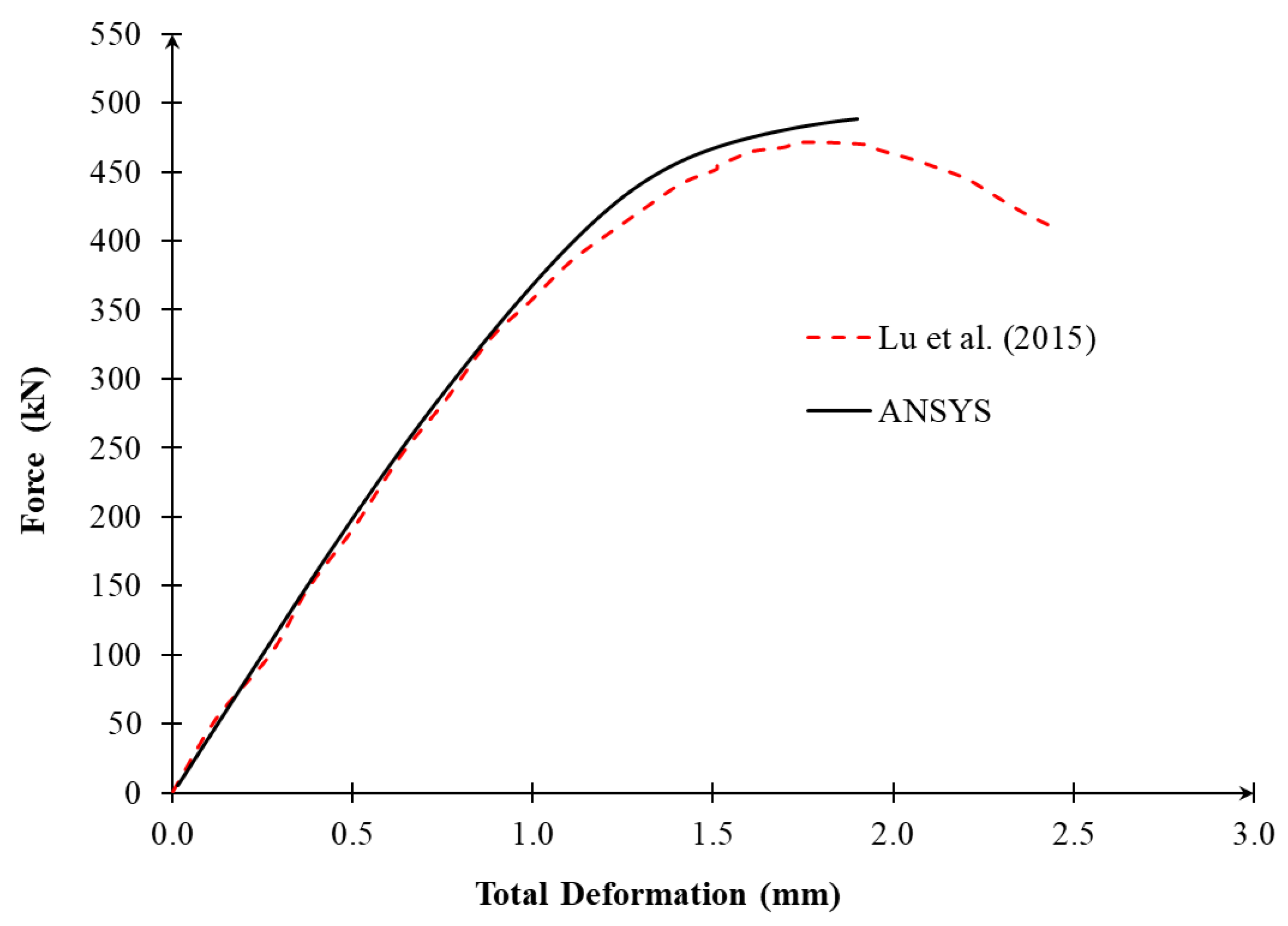
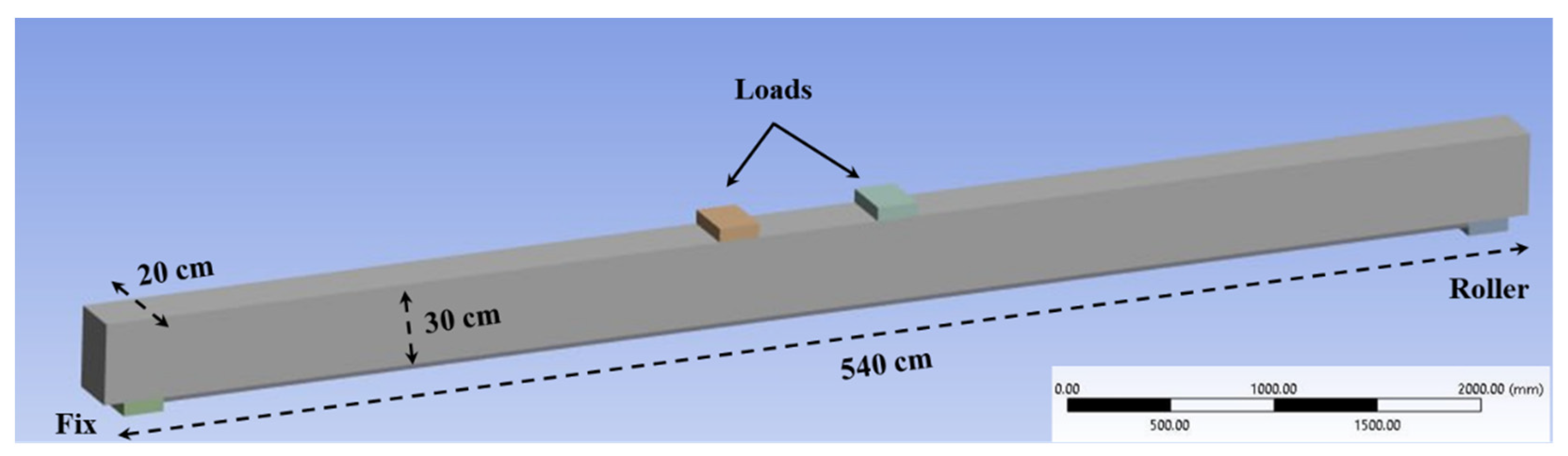
In order to assess the performance of an RC beam strengthened with CFRP and SMA, a full-scale reinforced concrete beam 540 × 20 × 30 cm was simulated using the finite element program ANSYS Figure 1. The Menétrey–Willam concrete constitutive model was used to simulate the behavior of concrete, and the boundary conditions in Figure 1 were set as roller support at the right end, and the support on the left is a fix for preventing the displacement in the x and y directions. To validate the model, a previously experimentally tested RC beam Lu et al. [31] was modeled. The beam was 700 mm long, 100 mm wide, 300 mm deep, and had an effective depth (h) of 270 mm. The numerical load–deflection curve was compared with the experimental one. As demonstrated in Figure 2, the load–deflection curves of the numerical results and experiments are in good agreement, which validates the model and confirms the overall accuracy of the calibration.
The SMA plate was represented using a simplified monotonic constitutive model to evaluate its stiffness contribution under static flexural loading. This modeling approach does not explicitly simulate the full thermomechanical behavior of SMA, including stress-induced martensitic phase transformation, cyclic superelasticity, temperature-dependent recovery, or self-centering response. Therefore, the SMA results in this study should be interpreted as the response of the adopted SMA material properties under monotonic loading, rather than a complete representation of SMA functional behavior.
The equivalent stiffness approach was adopted to ensure a rational comparison between CFRP and SMA strengthening systems. Since the strengthening plates had the same width, the axial stiffness equivalence was defined using the product of the elastic modulus and plate thickness. It should be noted that this equivalent stiffness approach is intended only as a comparative numerical framework for the selected beam geometry, material properties, and monotonic loading condition. It does not replace detailed design checks involving bond behavior, debonding, rupture, anchorage, cyclic loading, or long-term performance.
Since the CFRP and SMA plates have the same width, the stiffness equivalence was based on the axial stiffness per unit width, expressed as E t . Therefore, the equivalent stiffness condition was defined as:
E C F R P × t C F R P = E S M A × t S M A
Using the material properties adopted in the model, E C F R P = 227.5 GPa, E S M A = 60 GPa, and t C F R P = 5 mm, the equivalent SMA thickness becomes:
t S M A = 5 × 227.5 60 = 18.96   m
Accordingly, the stiffness-equivalent SMA model was revised to use an SMA plate thickness of 18.96 mm.
The analysis in this study was limited to monotonic static flexural loading. The loading procedure was selected to evaluate and compare the global flexural response, load–deformation behavior, crack-initiation tendency, and moment–curvature behavior of the control and strengthened beams under a controlled bending condition. Cyclic, seismic, fatigue, sustained loading, and long-term creep effects were not included in the present numerical model.
The numerical results obtained from the finite element model were validated by comparing them with the experimental beam reported by Lu et al. [31], and validated in a quantitative way. A comparison was made for the following key response parameters: first crack load, ultimate load, and midspan deflection at ultimate load. A percentage error was determined by using Equation (2). Besides comparison of the load–deflection curve, the dominant cracking/failure response was also compared qualitatively to check if the numerical model was able to capture the major experimental behavior presented in Table 1.
Error (%) = ExperimentalANSYS − Experimental × 100
The validation results show that the finite element model reproduced the main experimental response with acceptable accuracy for the nonlinear analysis of reinforced concrete beams. Therefore, the calibrated model was considered suitable for the comparative numerical investigation of the control, CFRP-strengthened, and SMA-strengthened beam configurations. However, the validation is limited to the available benchmark data, and further experimental testing of CFRP- and SMA-strengthened beams at equivalent stiffness levels is recommended.
After confirming the calibration of the numerical model, the large-span beam with the aforementioned dimensions was modeled. Four scenarios were considered: (1) without strengthening, (2) strengthened with 5 mm SMA, (3) strengthened with 5 mm CFRP, and (4) strengthened with 18.96 mm SMA. The mechanical properties of the CFRP sheets were adopted from Sika (SikaWrap system). The name of the manufacturer is Building Trust Sika, country Iraq, city Erbil [33]. while the properties of the other materials are presented in Table 2.
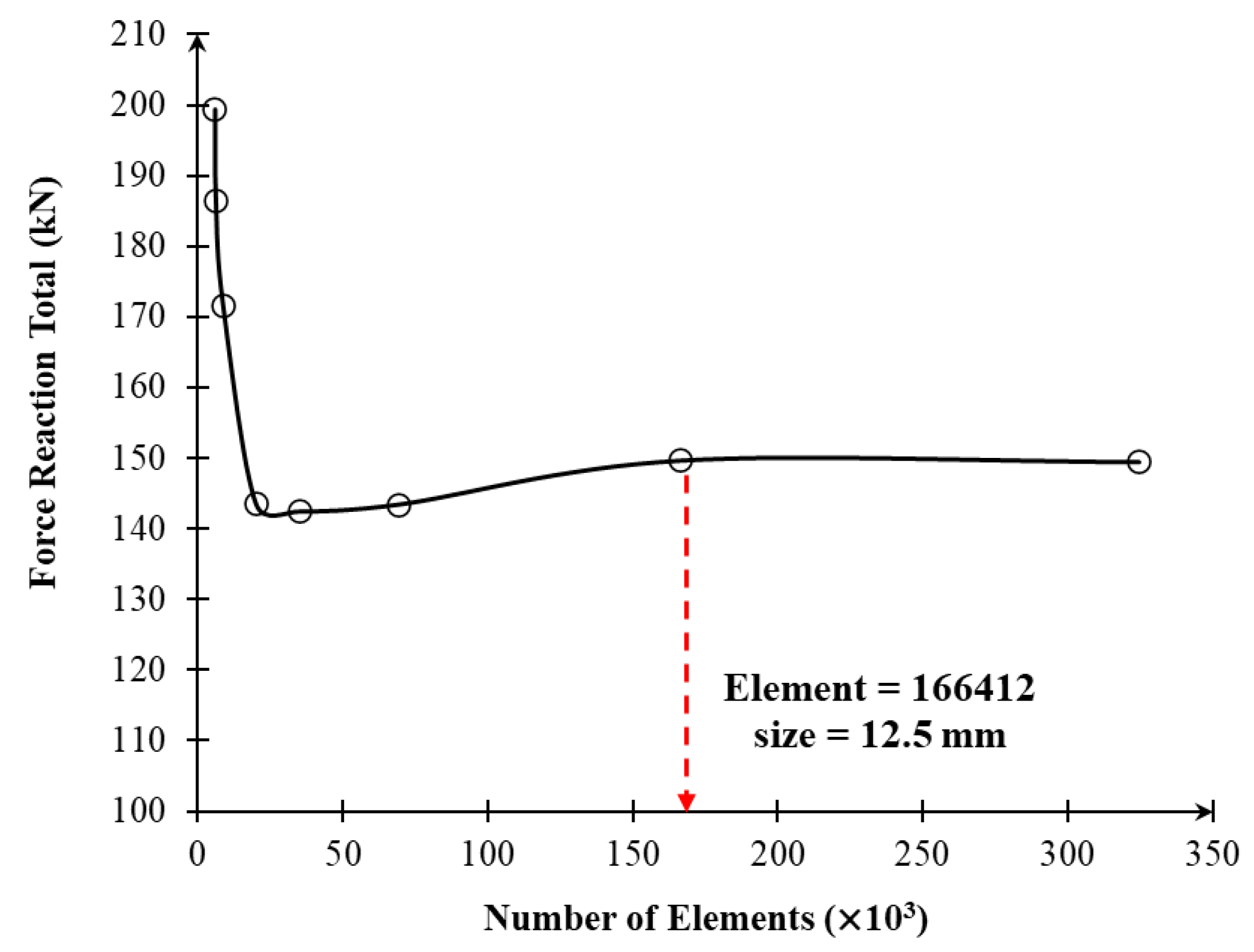
A three-dimensional eight-node solid element (SOLID65) was used to model the concrete. Rebars were represented by the LINK180 element, and loading and support plates were modeled as the three-dimensional structural solid element SOLID185. The smeared-crack formulation of the ANSYS concrete element was used to model the concrete. In this method, cracking is not modeled as an open crack surface, but rather, when the principal tensile stress reaches the specified tensile strength of concrete, the cracking effect is modeled by reducing the stiffness of the element in the direction of the crack. Thus, the model can simulate the effect of cracking on the global load–deformation response of the beam, but cannot include the discrete opening of cracks, crack width, or propagation in terms of fracture energy. Note that the assumed modeling approach is not a material damage plasticity model, and does not contain fracture-energy regularization. Thus, the numerical results are discussed primarily in terms of the flexural response at the global level, load–deformation behavior, stiffness variation, and comparative strengthening efficiency. The concrete crack/crushing status output, global stiffness changes, and comparison with the available experimental benchmark response were used to assess this crack and failure-related behavior, instead of just using the individual nodal stresses. A mesh convergence study was performed to find the right mesh size for balancing the computational time and accuracy. Here, the total reaction was plotted against the element number in Figure 3. For each mesh size, the total reaction force was assessed based on the number of elements. As shown in Figure 3, at a mesh size of 12.5 mm, the total reaction force converged at 166,412 elements, suggesting good mesh convergence.
To verify that the results obtained for the meshes were not overly sensitive to element size, a convergence study was performed. Several sizes of mesh were investigated, and the ultimate load and midspan deflection were compared as shown in Table 3. The convergence criterion used was the percentage difference in ultimate load for successive mesh refinements.
The mesh sensitivity table shows that coarse meshes produced noticeable variation in the predicted total reaction force. However, after refinement, the response became stable. The difference between the 12.5 mm and 10 mm meshes was only 0.15%, indicating that further refinement had a negligible effect on the predicted reaction force. Therefore, the 12.5 mm mesh was selected as the final mesh because it provided stable numerical results while avoiding the significantly higher computational cost of the 10 mm mesh.
The SMA plate was modeled with a simplified monotonic material model to analyze the contribution of stiffness under static flexural loading. The current modeling approach does not explicitly model the complete thermomechanical behavior of SMA, such as stress-induced martensitic phase transformation, cyclic superelasticity, temperature-dependent recovery, or self-centering response. Hence, from this study, the SMA results obtained are considered as the behavior of the SMA-adopted material properties under monotonic loading and not a complete representation of SMA functional behavior.
The perfect-bond assumption was used for concrete surface/externally bonded CFRP/SMA strengthening plates. The assumption was made in order to isolate the flexural stiffness contribution of the strengthening systems and to enable direct comparisons between CFRP and SMA strengthening configurations within the same numerical framework. As such, relative slip, adhesive damage, and separation between the strengthening plates and the concrete substrate were not explicitly taken into account in the present model.

3. Discussion on Results

3.1. Load–Deformation Behavior

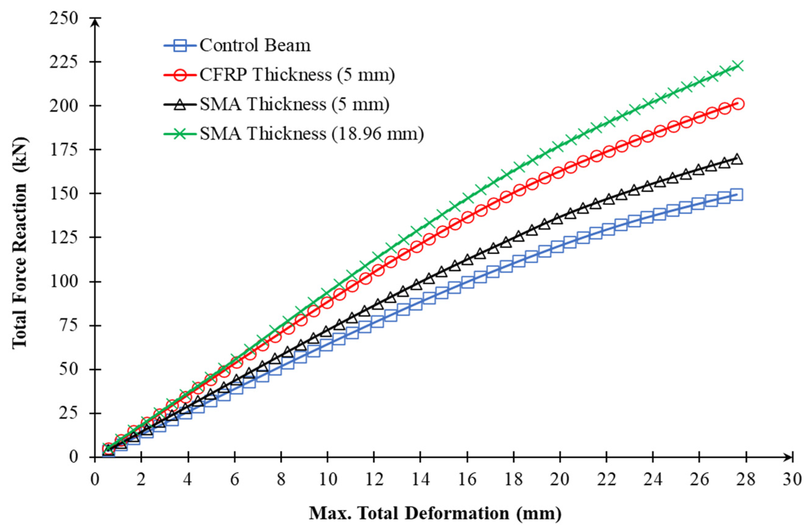
The load–deformation response of materials is a key parameter for evaluating stiffness, serviceability, cracking behavior, ductility, and overall structural performance. According to Figure 4, the almost linear and similar behavior of all specimens at the beginning of the deformation of about 0–5 mm range shows that the beams were still at the uncracked or slightly cracked elastic phase, in which the overall concrete section and internal steel reinforcement were the main factors that determined the global stiffness. At such an early stage, the strengthening systems were not yet mobilized enough, and material-specific effects like interfacial stress transfer, crack-bridging, and confinement enhancement were not yet well-developed; thus, the curves were still near each other. When the deformation became larger than this range, the responses increasingly diverged as cracks started to form and propagate, the stiffness of the concrete section declined, and the growing role of the strengthening materials began to play out. The control beam has the lowest reaction capacity, which means it has the least post-cracking stiffness and load resistance. No significant change was observed in the beam that was reinforced with 5 mm SMA as compared to the control specimen, which means that minimal improvement was made at the late deformation stage. Conversely, the 5 mm CFRP and 18.96 mm SMA beams exhibited a greater upward nonlinear response, which is indicative of their higher capacity to bear more load following the cracking. Out of all specimens, the SMA beam reinforced with the highest total reaction was the 18.96 mm, and this was followed by the CFRP reinforced beam, which validated that these strengthening schemes were the most efficient in enhancing post-cracking stiffness, load-carrying capacity, and deformation resistance of the RC beams. Table 4 shows numerical data.
From a mechanistic point of view, the strengthening effect is controlled by the compatibility between the concrete, the steel reinforcement, and the externally bonded plate after cracking. The uncracked concrete portion is significant in determining flexural stiffness prior to cracking, so the differences between the strengthened beams are not very great. Once the cracking has occurred, the tensile stiffness of the concrete is decreased, and the external strengthening system is more active in resisting tensile demand. Because of its high elastic modulus, the CFRP plate makes a significant contribution to tensile stiffness at relatively low thickness. The lower SMA modulus for the 5 mm plate, however, results in a lower contribution. Increasing the SMA thickness to meet the requirement of stiffness equivalency, the contribution of the SMA to axial stiffness is similar to that of CFRP, and the SMA-strengthened beam has significantly higher post-cracking axial stiffness and global flexural resistance. This means the strengthening efficiency relates to the combination of the properties of the material, the thickness of the plate, strain compatibility, and post-cracking force redistribution.

3.2. Assessment of First Crack Initiation in Control and Strengthened Beams

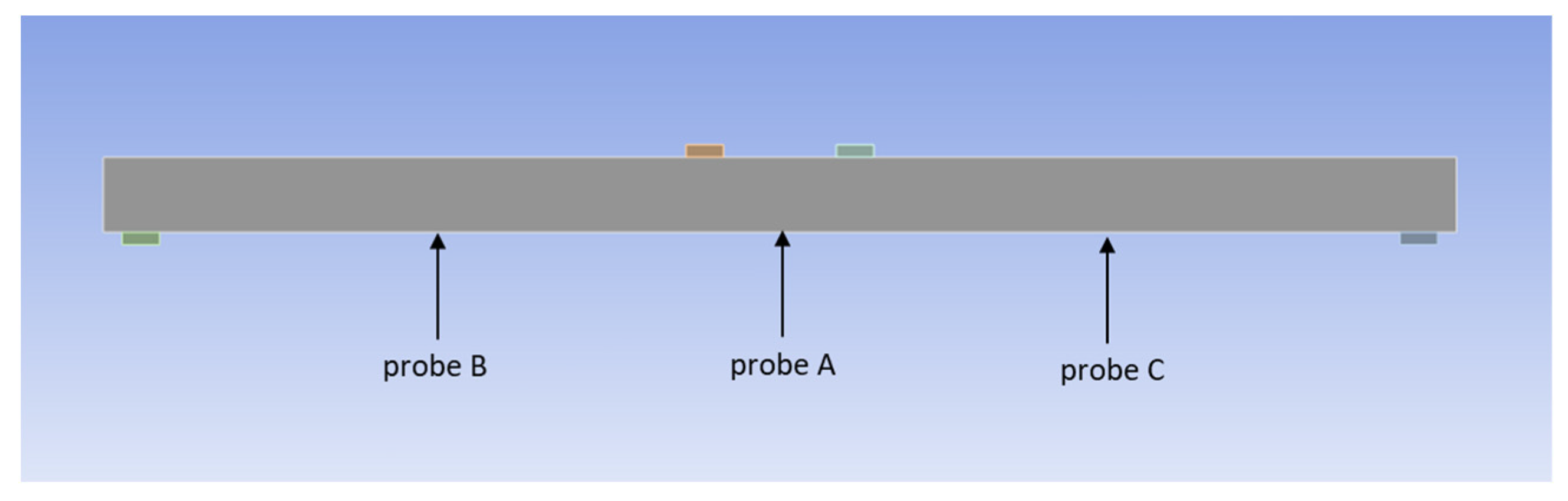
The positions of Probe A, B, and C that were used to provide local measurements of the maximum principal tensile stress in the beam are presented in Figure 5. The probes were located on the bottom fiber of the concrete member, which is the critical flexural tension zone. Probe A was mounted at the center of the bottom area, Probes B and C at the left and right sides of the area, respectively, to probe the series of crack initiation and the consequent tensile-stress concentration. Probe A was located at the bottom midspan area, where flexural tensile demand was likely to be the greatest with the applied loading. This is why it was chosen as the main tracking point of the first crack initiation, and Probes B and C to follow the probable sequence of the subsequent cracks.
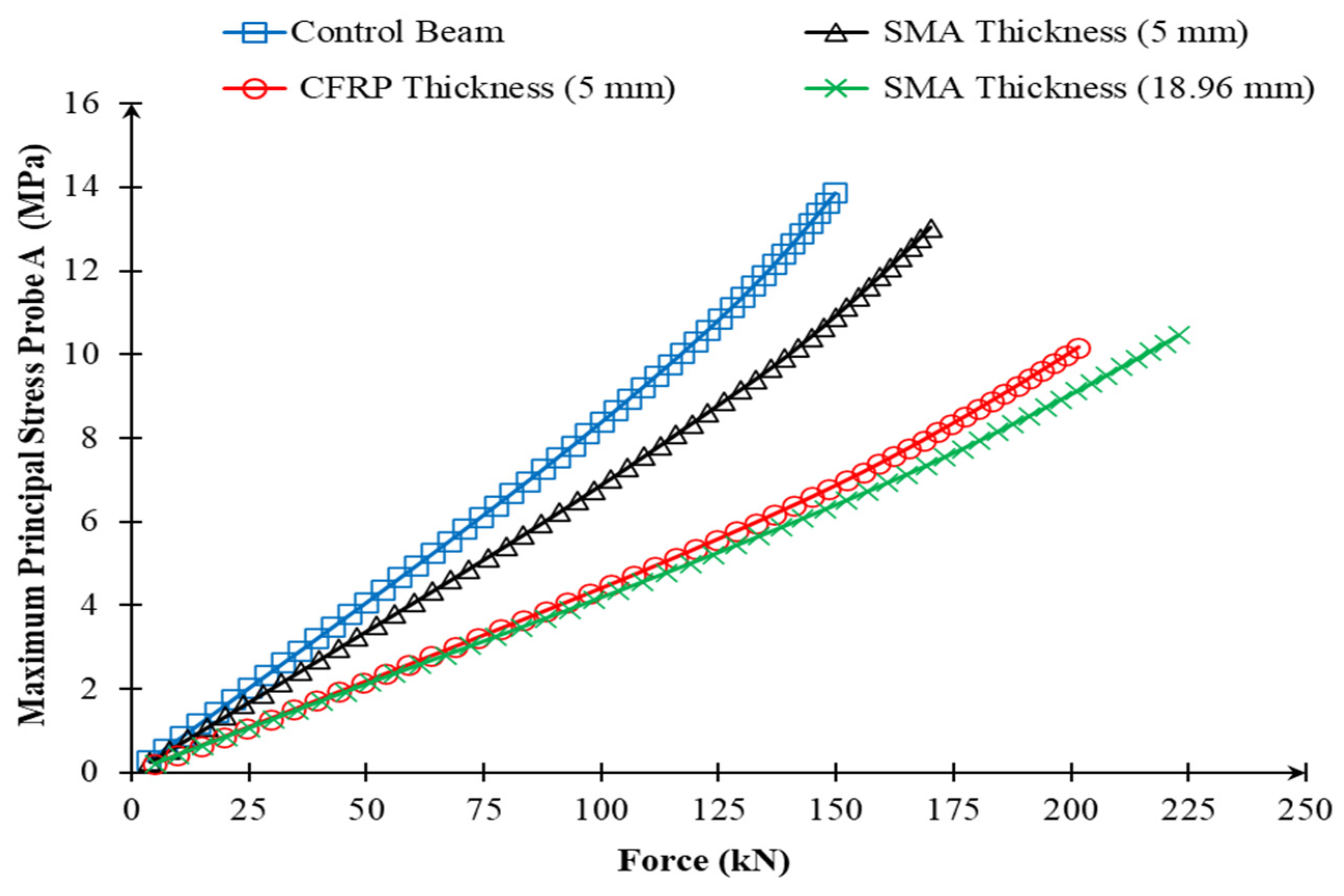
Figure 6 presents the load–probe A stress response for the control and strengthened beams. The maximum principal stress at Probe A rose progressively with an increase in load in all cases. The tensile-stress development rate was, however, varied among the beams. The steepest increase in stress was observed in the control beam, which showed the fastest accumulation of tensile stress in the critical area of the bottom fiber. Conversely, the increased beams demonstrated slower growth of stress, and this proved the positive influence of CFRP and SMA strengthening in postponing the crack propagation. The cases that were strengthened with the most positive response were CFRP 5 mm and SMA 18.96 mm, but SMA 5 mm did not improve as much.
Table 5 shows the probe-based first crack loads, the resultant percentage increment, as compared to the control beam, and the probable crack sequence of the studied specimens. The crack loads in the table were determined using the data of the load–probe stress by determining the first load level at which the maximum principal stress at any probe attained the concrete tensile strength level. The data of the load–probe stress were used to determine the crack loads in the table by locating the first level at the load level at which the maximum principal stress at a given probe reached the tensile strength level of the concrete, Ft = 3.4 MPa. On the occasions where the threshold was between two successive recorded points, the crack load was established by linear interpolation. Under this procedure, the earliest initiation of the control beam was 41.7 kN, then the first crack loads were 77.6 kN, 50.2 kN, and 82.97 kN in the case of CFRP 5 mm, SMA 5 mm, and SMA 18.96 mm beams, respectively. These values are relative increases of 86.1, 20.4, and 98.97% as opposed to the control beam. In each instance, the initial crack was found at Probe A, which verified that the central bottom-fiber zone was the most critical flexural tension zone in the loading configuration applied. Findings have shown that CFRP 5 mm and SMA 18.96 mm were very effective at slowing crack initiation, whereas only SMA 5 mm showed a moderate improvement compared to the control beam. Although the maximum first crack load was registered by SMA 18.96 mm, the difference between it and the CFRP 5 mm was small. Also, the subsequent crossing of the threshold at Probes B and C indicates that SMA 18.96 mm was more resistant to the consequent propagation of tensile-stress concentration along the beam, which is also consistent with its better load–deflection behavior. Thus, CFRP 5 mm can be discussed as a little bit more efficient in delaying first cracking, but SMA 18.96 mm could be considered as the most effective overall strengthening structure in terms of both crack-initiation resistance and global structural performance.

3.3. Moment–Curvature Behavior

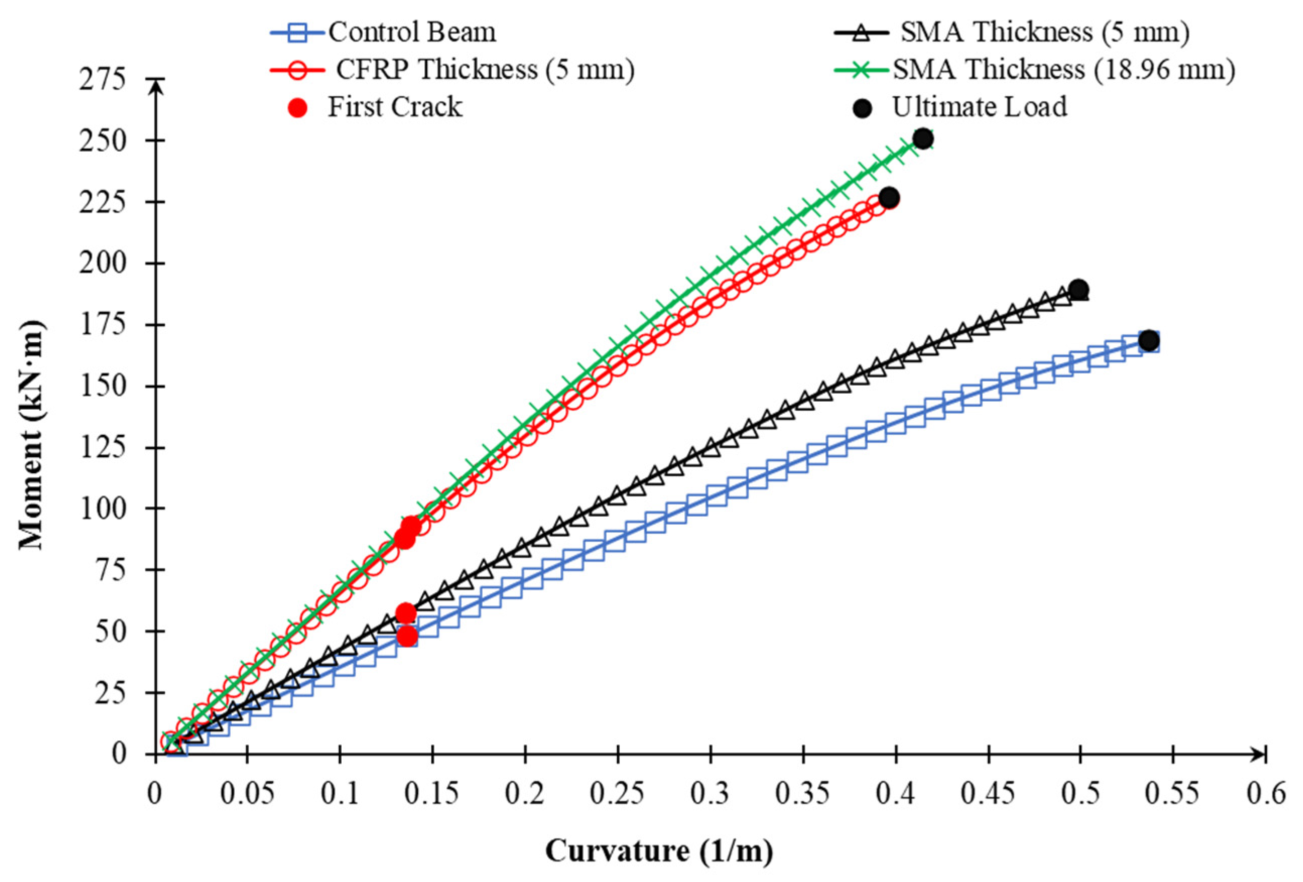
To evaluate the flexural performance of the strengthened RC beams, the moment–curvature responses of the strengthened beams were compared with each other and with the control beam, as shown in Figure 7. The linear part of the curve corresponds to the uncracked stage, and the slope represents the uncracked flexural stiffness. During this period, the strengthened beams showed greater curvature than the control beam, reflecting the increased flexural stiffness from the contribution of CFRP and/or SMA strengthening. The cracking points indicate the end of the uncracked stage and the beginning of tensile cracking in the concrete. Post-cracking, all beams sustained increases in moment but at a lower slope, reflecting a loss in post-cracking stiffness due to stiffness loss in the cracked tension zone. The post-cracking stiffness of the strengthened beams was higher than that of the control beam, which showed their ability to restrain tensile-stress concentration and redistribute stresses. The yielding zone is the stage close to reinforcement yielding, in which the moment–curvature response accelerates, as a result of stiffness loss and the development of inelastic response. Overall, the strengthened beams exhibited better ductility and flexural capacity than the control beam, as indicated by higher ultimate values of moment and curvature. SMA 18.96 mm showed the best overall moment–curvature response of the investigated configurations, with the highest ultimate moment and the best overall section response, while CFRP 5 mm also led to a sizeable improvement and very good crack-initiation resistance. The SMA 5 mm beam improved the section response relative to the control beam, but the improvement was less significant than that provided by CFRP 5 mm and SMA 18.96 mm. The findings clearly show that the section response improved due to strengthening with CFRP and SMA in terms of stiffness, cracking, post-cracking, and moment capacities, with SMA 18.96 mm contributing the most. The key features of the moment–curvature responses are shown in Table 6. As expected from the curves in Figure 7, the retrofitted beams had higher cracking load, better post-cracking stiffness, and higher ultimate load than the control beam.
In the constant-moment region, the moment–curvature response has been obtained from the numerical model via a curvature averaging technique. The bending moment has been determined based on the applied load and shear span. The moment was calculated as the load applied plotted against the four-point bending configuration, in this case, for which the total applied load is plotted.
M = P 2 a
Here, P is the whole applied load, and a is the shear span. Average curvature was determined in the following manner: The difference between the top compressive fiber and the bottom tensile fiber divided by the depth of the beam.
ϕ = ε c ε t d s
where εc and εt are the respective average strains of the top and bottom fibers. are the average strains of the top and bottom fibers, respectively. ds is the height between the points at which the strain was measured. Local stress concentration and cracking were minimized by averaging the strains over a specified length in the constant moment region.
As the concrete was modeled as a smeared crack, the computed curvature is an average curvature response of the selected area, not as an exact local curvature at a discrete crack. The use of moment–curvature curves is, therefore, primarily for comparative purposes to evaluate the control and strengthened beams under the same set of numerical conditions. This calculation procedure for extracting the moment–curvature response from the FEA is described in Appendix A. The moment was determined from the sum of the applied load and shear span; the curvature was derived from the average longitudinal strain difference between the compressive fiber at the top and the tensile fiber at the bottom of the shear span in the constant-moment region was used for the calculation of the curvature.

3.4. Practical Implications of CFRP and SMA Strengthening

From a practical perspective, CFRP strengthening has advantages related to its low weight, corrosion resistance, commercial availability, and established use in structural retrofitting applications. Its installation procedure is relatively well understood and commonly involves surface preparation, adhesive application, bonding of the CFRP plate or sheet, and curing. In contrast, SMA strengthening may provide additional functional advantages, such as recovery capability, prestressing potential, and damage-control behavior. However, SMA systems may involve higher material cost, more complex installation requirements, anchorage considerations, and possible temperature-dependent activation procedures. Therefore, although the stiffness-equivalent SMA configuration showed favorable numerical flexural performance in this study, practical implementation should also consider cost, availability, installation difficulty, anchorage, bond performance, and long-term durability.

4. Limitations of the Study

The present model offers an approximate smeared-crack approach to the concrete cracking, but does not consider the development of cracks in terms of a fracture energy or crack width evolution and concrete damage plasticity. Moreover, the results are restricted to monotonic static loading and the particular beam geometry, material characteristics, and strengthening configurations selected. Thus, the results of the crack response and final loads obtained from the prediction must be treated as a set of idealized numbers given the modeling assumptions used. Future research will involve fracture energy-regularized damage modeling, cohesive interface law, and experimental validation of the crack pattern.
The present study is limited to monotonic static flexural loading and to the selected beam geometry, material properties, and strengthening configurations. The concrete model provides an approximate smeared-crack representation of cracking, but fracture-energy-based crack propagation and concrete damage plasticity were not explicitly considered. The SMA material was represented using a simplified monotonic constitutive model; therefore, temperature-dependent phase transformation, cyclic superelasticity, and self-centering behavior were outside the scope of this work. In addition, a perfect bond was assumed between the concrete and the external strengthening plates, while adhesive debonding, interfacial fracture, and concrete cover separation were not explicitly modeled. Therefore, the predicted ultimate loads and strengthening efficiencies should be interpreted as idealized numerical responses under the adopted assumptions. Future research should include experimental validation, cohesive interface modeling, cyclic loading, and full-scale assessment of CFRP- and SMA-strengthened RC beams.
The SMA material model used in this study is simplified and does not include temperature-dependent phase transformation, cyclic superelasticity, self-centering behavior, or the shape memory recovery process. Therefore, the results should not be generalized to cyclic, seismic, or thermally activated SMA applications without further modeling and experimental verification.
A perfect bond was assumed for the interface behavior between the concrete and externally bonded strengthening plates. Adhesive debonding, interfacial shear failure, peeling stresses, or concrete cover separation were not specifically simulated. Hence, the ultimate loads predicted may be upper-bound solutions for an ideal bond. Future studies should consider cohesive zone models, traction-separation laws, or contact/interface elements to investigate bond-slip, debonding, and interfacial fracture behavior more realistically.
A quantitative cost-benefit analysis was not performed in the present study; therefore, future work should evaluate the economic feasibility, installation requirements, and construction practicality of CFRP and SMA strengthening systems.

5. Conclusions

In this paper, the flexural behavior of RC beams with externally bonded CFRP and SMA plates was numerically analyzed based on the equivalent stiffness method. The primary goal was to compare the strengthening efficiency of the CFRP and SMA systems on a rational basis, taking into account the contribution of axial stiffnesses, instead of comparing equal thicknesses of plates. Based on the stiffness-equivalence condition, E C F R   ×   t C F R P = E S M A   ×   t S M A , four configurations of the beams were analyzed: the unstrengthened control beam, SMA 5 mm, CFRP 5 mm, and SMA 18.96 mm. The results indicated that all of the strengthening systems could enhance the flexural response as compared to the control beam, but to a different extent, depending heavily on the stiffness of the external strengthening plate. The first crack load of the control beam was 41.7 kN, indicating that the crack was initiated first. This was increased to 50.2 kN with the SMA 5 mm beam, which is about a 20.4% improvement. This enhancement was limited when compared with the CFRP plate, due to the lower contribution of axial stiffness of the 5 mm SMA plate. The CFRP 5 mm beam was able to reach a first crack load of 77.6 kN, which is about 86.1% higher than the control beam. This was a considerable rise, as a result of the high elastic modulus of CFRP, which resulted in an increase in tensile stiffness, time to failure of cracking, and better post-cracking behavior. The SMA 18.96 mm beam with the highest stiffness, which was referred to as the stiffness-equivalent beam, had produced the highest first-crack load of 82.97 kN. Compared to the control beam, it is about 99.0% higher, and compared to the CFRP 5 mm beam, it is about 6.9% higher. This result is in agreement with the fact that the reduced performance of the SMA 5 mm beam was mostly due to a lack of stiffness and not to the lack of effectiveness of SMA as a strengthening material. The SMA thickness was then increased to impart the same stiffness as the CFRP beam, and the strengthening performance was greatly enhanced, and slightly higher than that of the CFRP beam, with respect to crack-initiation resistance. In summary, the numerical results show that the efficiency of the strengthening of the externally bonded plates is controlled primarily by the contribution of the stiffness of the plates in the axial direction. Thus, comparing the responses of equal-thickness CFRP and SMA may be misleading, due to the difference in elastic moduli of the two materials. Results confirmed the use of a framework of stiffness-equivalents for a more meaningful assessment of strengthening performance. Nevertheless, the results should be interpreted in the light of the limitations of the numerical model. A smeared-crack approach was used for the representation of the concrete, and a perfect bond between the concrete and the strengthening plates was assumed; moreover, the SMA material was modeled under monotonic loading by adopting a simplified mechanical representation (without full thermomechanical superelastic behavior). So, more experimental validation and detailed interface modeling, cyclic loading analysis, and field-scale verification are required prior to direct design application.

Author Contributions

Conceptualization, J.T., A.D. and M.A.M.; Methodology, J.T., M.A.M. and A.D.; Software, J.T. and M.A.M.; Validation, J.T. and A.D.; Formal analysis, J.T.; Investigation, J.T.; Data curation, J.T.; Writing—original draft, J.T.; Writing—review & editing, M.A.M. and A.D.; Supervision, M.A.M. and A.D.; Project administration, M.A.M. All authors have read and agreed to the published version of the manuscript.

Funding

This research received no external funding.

Data Availability Statement

The raw data supporting the conclusions of this article will be made available by the authors on request.

Conflicts of Interest

The authors declare no conflicts of interest.

Appendix A

Table A1. Moment–Curvature Calculation Procedure.
Control BeamSMA (5mm)CFRP (5mm)SMA (18.96mm)
Strain Probe TOP (Maximum Principal) [mm/mm]Strain Probe Bttom (Maximum Principal) [mm/mm]Curvature (mm)Curvature (m)Force Reactio NForce Reaction KNMoment KN.mStrain Probe TOP (Maximum Principal) [mm/mm]Strain Probe Bttom (Maximum Principal) [mm/mm]Curvature (mm)Curvature (m)Force Reactio NForce Reaction KNMoment KN.mStrain Probe TOP (Maximum Principal) [mm/mm]Strain Probe Bttom (Maximum Principal) [mm/mm]Curvature (mm)Curvature (m)Force Reactio NForce Reaction KNMoment KN.mStrain Probe TOP (Maximum Principal) [mm/mm]Strain Probe Bttom (Maximum Principal) [mm/mm]Curvature (mm)Curvature (m)Force Reactio NForce Reaction KNMoment KN.m
2.6373E-060.0000113231.13125E-050.011312451−1792.6−1.79264.033352.8976E-060.0000104151.04034E-050.01040341−2000.7−2.00074.45155753.4465E-068.4061E-068.39231E-060.008392314−2460.1−2.46015.5352253.49E-068.21E-068.19493E-060.008194926−2529.5−2.52955.691375
5.2741E-060.0000226442.26229E-050.022622904−3584.8−3.58488.06585.7947E-060.0000208272.08038E-050.020803821−4001.2−4.00128.902676.8926E-060.000016811.67824E-050.01678243−4919.9−4.919911.0697756.99E-061.64E-051.63881E-050.016388053−5059.2−5.059211.3832
0.0000079110.0000339643.39324E-050.033932356−5377.1−5.377112.0984758.6919E-060.000031243.12052E-050.031205232−6001.6−6.001613.353561.0339E-050.0000252132.51716E-050.025171644−7379.6−7.379616.60411.05E-052.46E-052.45821E-050.024582076−7589.6−7.589617.0766
0.0000105480.0000452854.52428E-050.045242808−7169.3−7.169316.1309250.0000115890.0000416524.16056E-050.041605644−8002−8.00217.804451.3785E-050.0000336163.35609E-050.03356086−9839.4−9.839422.138651.40E-053.28E-053.27761E-050.0327761−10,121−10.12122.77225
0.0000131850.0000566055.65523E-050.05655226−8961.6−8.961620.16360.0000144860.0000520655.20071E-050.052007056−10,002−10.00222.254451.7231E-050.000042024.19511E-050.041951076−12,299−12.29927.672751.75E-054.10E-054.09721E-050.040972124−12,652−12.65228.467
0.0000158210.0000679266.78627E-050.067862716−10,754−10.75424.19650.0000173830.0000624786.24085E-050.062408468−12,003−12.00326.7066752.0677E-050.0000504235.03403E-050.050340292−14,759−14.75933.207752.10E-054.93E-054.91681E-050.049168144−15,184−15.18434.164
0.0000184580.0000792477.91732E-050.079173168−12,546−12.54628.22850.0000202850.0000729067.28249E-050.07282486−14,010−14.0131.172252.4123E-050.0000588265.87295E-050.058729508−17,219−17.21938.742752.45E-055.75E-055.73652E-050.057365164−17,716−17.71639.861
0.0000210950.0000905679.04826E-050.09048262−14,338−14.33832.26050.0000231880.000083348.32472E-050.083247248−16,020−16.0235.64452.7569E-050.000067236.71197E-050.067119724−19,678−19.67844.27552.80E-056.57E-056.55642E-050.06556418−20,251−20.25145.56475
0.0000237310.000101890.0001017950.101795076−16,130−16.1336.29250.0000260920.0000937779.36726E-050.093672632−18,031−18.03140.1189753.1015E-050.0000756337.55089E-050.07550894−22,138−22.13849.81053.15E-057.39E-057.38071E-050.073807124−22,819−22.81951.34275
0.0000263650.000113190.0001130850.11308454−17,918−17.91840.31550.0000289950.000104210.0001040940.10409402−20,040−20.0444.5893.4461E-050.0000840368.38982E-050.083898156−24,595−24.59555.338753.50E-058.22E-058.2093E-050.082092992−25,416−25.41657.186
0.0000289980.00012450.0001243840.124384008−19,703−19.70344.331750.00003190.000114650.0001145220.1145224−22,048−22.04849.05683.7907E-050.000092449.22884E-050.092288372−27,049−27.04960.860253.86E-059.06E-059.04318E-050.090431772−28,049−28.04963.11025
0.0000316310.00013580.0001356730.135673476−21,484−21.48448.3390.0000348040.000125090.0001249510.124950784−24,053−24.05353.5179254.1352E-050.000100840.0001006750.100674592−29,500−29.566.3754.21E-059.90E-059.88414E-050.098841432−30,734−30.73469.1515
0.0000342630.00014710.0001469630.146962948−23,263−23.26352.341750.0000377060.000135520.0001353690.135369176−26,055−26.05557.9723754.4796E-050.000109240.0001090610.109060816−31,948−31.94871.8834.57E-051.07E-040.0001072970.10729702−33,449−33.44975.26025
0.0000368910.000158380.0001582320.158232436−25,036−25.03656.3310.0000406080.000145950.0001457880.145787568−28,056−28.05662.42464.8239E-050.000117630.0001174370.117437044−34,392−34.39277.3824.93E-051.16E-040.0001157530.115752604−36,158−36.15881.3555
0.0000395160.000169650.0001694920.169491936−26,804−26.80460.3090.0000435090.000156370.0001561960.156195964−30,051−30.05166.8634755.1681E-050.000126030.0001258230.125823276−36,826−36.82682.85855.29E-051.24E-040.0001241780.124178224−38,837−38.83787.38325
0.0000421360.00018090.0001807310.180731456−28,559−28.55964.257750.0000464090.00016680.0001666140.166614364−32,037−32.03771.2823255.5122E-050.000134420.00013420.134199512−39,247−39.24788.305755.65E-051.33E-040.0001325940.132593888−41,487−41.48793.34575
0.0000447520.000192120.0001919410.191940992−30,299−30.29968.172750.0000493080.000177220.0001770230.177022768−34,012−34.01275.67675.8557E-050.00014280.0001425660.142565772−41,651−41.65193.714756.01E-051.41E-040.000140980.140979584−44,114−44.11499.2565
0.0000473650.000203340.0002031510.20315054−32,027−32.02772.060750.0000522020.000187620.0001874110.187411192−35,975−35.97580.0443750.000061990.000151170.0001509220.15092204−44,041−44.04199.092256.37E-051.50E-040.0001493750.149375288−46,728−46.728105.138
0.000049970.000214520.000214320.21432012−33,741−33.74175.917250.0000550950.000198020.00019780.19779962−37,924−37.92484.38096.5414E-050.000159530.0001592680.159268344−46,412−46.412104.4276.72E-051.58E-040.0001577510.157751012−49,328−49.328110.988
0.0000525740.00022570.000225490.225489704−35,442−35.44279.74450.000057980.000208390.0002081580.20815808−39,858−39.85888.684056.8831E-050.000167860.0001675850.167584676−48,764−48.764109.7197.08E-051.66E-040.0001661270.166126736−51,917−51.917116.81325
0.0000551760.000236870.0002366490.236649296−37,135−37.13583.553750.0000608590.000218740.0002184970.218496564−41,777−41.77792.9538257.2243E-050.000176190.0001759010.175901028−51,097−51.097114.968257.44E-051.75E-040.0001744920.174492488−54,488−54.488122.598
0.0000577690.0002480.0002477690.247768924−38,813−38.81387.329250.0000637340.000229080.0002288250.228825064−43,679−43.67997.1857757.5639E-050.000184480.0001841770.184177444−53,399−53.399120.147757.79E-051.83E-040.0001828380.182838272−57,032−57.032128.322
0.000060360.000259130.0002588890.25888856−40,476−40.47691.0710.0000666020.000239390.0002391240.239123592−45,563−45.563101.3776757.9023E-050.000192740.0001924240.192423908−55,662−55.662125.23958.15E-051.92E-040.0001911740.191174088−59,540−59.54133.965
0.0000629430.000270220.0002699680.269968228−42,122−42.12294.77450.000069460.000249680.0002494020.24940216−47,427−47.427105.5250758.2391E-050.000200970.000200640.200640436−57,884−57.884130.2398.50E-052.00E-040.000199460.199459976−62,010−62.01139.5225
0.0000655170.000281270.0002810080.281007932−43,749−43.74998.435250.0000723140.000259940.0002596510.259650744−49,264−49.264109.61240.000085740.000209150.0002088070.20880704−60,067−60.067135.150758.85E-052.08E-040.0002077260.207725916−64,444−64.444144.999
0.0000680870.000292310.0002920380.292037652−45,352−45.352102.0420.0000751530.000270160.0002698590.269859388−51,070−51.07113.630758.9075E-050.000217290.0002169340.2169337−62,215−62.215139.983759.20E-052.16E-040.0002159520.215951912−66,849−66.849150.41025
0.0000706450.00030330.0003030170.30301742−46,929−46.929105.590250.0000779780.000280330.0002800180.280018088−52,847−52.847117.5845759.2394E-050.000225410.000225040.225040424−64,332−64.332144.7479.55E-052.25E-040.0002241580.224157948−69,222−69.222155.7495
0.0000731880.000314230.0003139370.313937248−48,478−48.478109.07550.0000807940.000290470.0002901470.290146824−54,596−54.596121.47619.5696E-050.000233480.0002330970.233097216−66,409−66.409149.420259.90E-052.33E-040.0002323340.232334044−71,562−71.562161.0145
0.0000757210.000325110.0003248070.324807116−50,002−50.002112.50450.0000835970.000300570.0003002360.300235612−56,321−56.321125.3142259.8978E-050.00024150.0002411040.241104088−68,445−68.445154.001251.02E-042.41E-040.000240480.2404802−73,866−73.866166.1985
0.0000782430.000335950.0003356370.335637028−51,501−51.501115.877250.0000863930.000310630.0003102840.310284428−58,022−58.022129.098950.000102240.000249480.0002490710.24907104−70,440−70.44158.491.06E-042.49E-040.0002485760.24857644−76,133−76.133171.29925
0.0000807550.000346750.0003464270.34642698−52,977−52.977119.198250.0000891810.000320680.0003203230.320323276−59,707−59.707132.8480750.000105470.000257390.0002569680.25696812−72,387−72.387162.870751.09E-042.57E-040.0002566230.2566228−78,353−78.353176.29425
0.0000832570.00035750.0003571670.357166972−54,431−54.431122.469750.0000919740.000330750.0003303820.330382104−61,395−61.395136.6038750.000108670.000265220.0002647850.26478532−74,272−74.272167.1121.13E-042.65E-040.0002645890.26458928−80,514−80.514181.1565
0.0000857480.000368210.0003678670.367867008−55,863−55.863125.691750.0000947820.000340880.0003405010.340500872−63,101−63.101140.3997250.000111830.000272970.0002725230.27252268−76,096−76.096171.2161.16E-042.73E-040.0002724960.27249584−82,619−82.619185.89275
0.0000882250.000378870.0003785170.3785171−57,270−57.27128.85750.0000976010.000351050.000350660.350659596−64,817−64.817144.2178250.000114960.000280630.000280170.28017016−77,851−77.851175.164751.19E-042.81E-040.0002803130.28031256−84,649−84.649190.46025
0.0000906870.000389460.0003890970.389097252−58,652−58.652131.9670.00010040.000361170.0003607680.3607684−66,500−66.5147.96250.000118050.00028820.0002877280.2877278−79,536−79.536178.9561.23E-042.89E-040.0002880390.28803948−86,609−86.609194.87025
0.0000931320.000399990.0003996170.399617472−60,006−60.006135.01350.000103160.000371130.0003707170.37071736−68,102−68.102151.526950.000121110.00029570.0002952160.29521556−81,166−81.166182.62351.26E-042.96E-040.0002956970.29569652−88,513−88.513199.15425
0.0000955580.000410440.0004100580.410057768−61,330−61.33137.99250.000105860.000380870.0003804470.38044656−69,603−69.603154.8666750.000124140.000303120.0003026230.30262344−82,746−82.746186.17851.29E-043.04E-040.0003032940.30329364−90,367−90.367203.32575
0.0000979640.000420810.0004204180.420418144−62,616−62.616140.8860.00010850.000390410.0003899760.389976−71,019−71.019158.0172750.000127140.00031050.0003099910.30999144−84,284−84.284189.6391.32E-043.11E-040.0003108410.31084084−92,179−92.179207.40275
0.000100340.000431070.0004306690.43066864−63,859−63.859143.682750.00011110.000399810.0003993660.3993656−72,367−72.367161.0165750.000130130.000317830.0003173090.31730948−85,787−85.787193.020751.36E-043.19E-040.0003183380.31833792−93,947−93.947211.38075
0.00010270.000441220.0004408090.4408092−65,060−65.06146.3850.000113660.000409110.0004086550.40865536−73,668−73.668163.91130.00013310.000325120.0003245880.3245876−87,259−87.259196.332751.39E-043.26E-040.0003257950.32579464−95,677−95.677215.27325
0.000105020.000451240.000450820.45081992−66,210−66.21148.97250.000116220.000418340.0004178750.41787512−74,936−74.936166.73260.000136140.000332390.0003318450.33184544−88,702−88.702199.57951.42E-043.34E-040.0003332210.333221−97,377−97.377219.09825
0.000107310.000461110.0004606810.46068076−67,305−67.305151.436250.000118750.000427510.0004270350.427035−76,170−76.17169.478250.000139260.000339630.0003390730.33907296−90,122−90.122202.77451.46E-043.41E-040.0003406070.34060692−99,044−99.044222.849
0.000109570.000470860.0004704220.47042172−68,353−68.353153.794250.000121270.000436620.0004361350.43613492−77,369−77.369172.1460250.000142450.000346850.000346280.3462802−91,521−91.521205.922251.49E-043.49E-040.0003479720.3479724−1.01E+05−100.68226.53
0.000111810.000480510.0004800630.48006276−69,362−69.362156.06450.000123760.000445680.0004451850.44518496−78,538−78.538174.747050.000145760.000354050.0003534670.35346696−92,900−92.9209.0251.53E-043.56E-040.0003553080.35530784−1.02E+05−102.3230.175
0.000114020.000490090.0004896340.48963392−70,339−70.339158.262750.000126250.000454680.0004541750.454175−79,678−79.678177.283550.000149150.000361230.0003606330.3606334−94,260−94.26212.0851.56E-043.63E-040.0003626150.36261468−1.04E+05−103.89233.7525
0.000116220.000499590.0004991250.49912512−71,287−71.287160.395750.000128720.000463650.0004631350.46313512−80,797−80.797179.7733250.000152560.000368390.000367780.36777976−95,600−95.6215.11.59E-043.71E-040.0003699030.36990304−1.05E+05−105.46237.285
0.000118410.000509050.0005085760.50857636−72,211−72.211162.474750.000131190.000472570.0004720450.47204524−81,896−81.896182.21860.000155760.000375530.0003749070.37490696−96,923−96.923218.076751.62E-043.78E-040.0003771640.37716376−1.07E+05−107.01240.7725
0.000120590.000518460.0005179780.51797764−73,114−73.114164.50650.000133730.000481490.0004809550.48095508−82,976−82.976184.62160.000158520.000382650.0003820160.38201592−98,228−98.228221.0131.64E-043.85E-040.0003844140.38441448−1.09E+05−108.54244.215
0.000122750.000527810.0005273190.527319−73,997−73.997166.493250.000136320.000490370.0004898250.48982472−84,038−84.038186.984550.000160840.000389750.0003891070.38910664−99,517−99.517223.913251.66E-043.92E-040.0003916050.39160512−1.10E+05−110.04247.59
0.00012490.000537120.000536620.5366204−74,861−74.861168.437250.000138930.000499240.0004986840.49868428−85,083−85.083189.3096750.000163020.000396840.0003961880.39618792−100,790−100.79226.77751.69E-043.99E-040.0003987260.39872576−1.12E+05−111.5250.875

References

  1. Jani, J.M.; Leary, M.; Subic, A.; Gibson, M.A. A review of shape memory alloy research, applications and opportunities. Mater. Des. 2014, 56, 1078–1113. [Google Scholar] [CrossRef]
  2. Chang, W.S.; Araki, Y. Use of shape-memory alloys in construction: A critical review. Proc. Inst. Civ. Eng. Civ. Eng. 2016, 169, 87–95. [Google Scholar] [CrossRef]
  3. Michels, J.; Shahverdi, M.; Czaderski, C.; Schranz, B. Iron based shape memory alloy strips, part 2: Flexural strengthening of RC beams. In Proceedings of the Fourth International Conference on Smart Monitoring, Assessment and Rehabilitation of Civil Structures (SMAR 2017), Zurich, Switzerland, 13–15 September 2017; pp. 1–9. [Google Scholar]
  4. Moulika, D.N.; Vasireddy, R.; Raju, P.P. Modelling and analysis of reinforced concrete beam under. Int. J. Civ. Eng. Technol. 2017, 8, 1103–1111. [Google Scholar]
  5. Hong, K.; Lee, S.; Yeon, Y.; Jung, K. Flexural Response of Reinforced Concrete Beams Strengthened with Near-Surface-Mounted Fe-Based Shape-Memory Alloy Strips. Int. J. Concr. Struct. Mater. 2018, 12, 45. [Google Scholar] [CrossRef]
  6. Halahla, A. Study the Behavior of Reinforced Concrete Beam Using Finite Element Analysis. In Proceedings of the 3rd World Congress on Civil, Structural, and Environmental Engineering (CSEE’18), Budapest, Hungary, 8–10 April 2018. [Google Scholar] [CrossRef]
  7. Rahman, R.; Dirar, S.; Jemaa, Y.; Theofanous, M. Experimental Behavior and Design of Exterior Reinforced Concrete Beam-Column Joints Strengthened with Embedded Bars. J. Compos. Constr. 2018, 22, 1–15. [Google Scholar] [CrossRef]
  8. Mashrei, M.A. Flexural Strengthening of Reinforced Concrete Beams Using Carbon Fiber Reinforced Polymer (CFRP) Sheets with Grooves. Lat. Am. J. Solids Struct. 2019, 16, 1–13. [Google Scholar] [CrossRef]
  9. Guo, R.; Ren, Y.; Li, M.; Hu, P.; Du, M.; Zhang, R. Experimental study on flexural shear strengthening effect on low-strength RC beams by using FRP grid and ECC. Eng. Struct. 2021, 227, 111434. [Google Scholar] [CrossRef]
  10. Abbood, I.S.; Odaa, S.; Hasan, K.F.; Jasim, M.A. Materials Today: Proceedings Properties evaluation of fiber reinforced polymers and their constituent materials used in structures—A review. Mater. Today Proc. 2021, 43, 1003–1008. [Google Scholar] [CrossRef]
  11. Raza, S.; Shafei, B.; Saiidi, M.S.; Motavalli, M.; Shahverdi, M. Shape memory alloy reinforcement for strengthening and self-centering of concrete structures—State of the art. Constr. Build. Mater. 2022, 324, 126628. [Google Scholar] [CrossRef]
  12. Hussein, A.N.; Alsaad, A.J.; Rasoul, Z.M.R.A. Flexural Behavior of Sustainable Reinforced Concrete Beam Strengthened by External Carbon Fiber Reinforced Polymer (CFRP) Sheets. 2022. Available online: https://www.researchgate.net/publication/364607570_Flexural_Behavior_of_Sustainable_Reinforced_Concrete_Beam_Strengthened_by_External_Carbon_Fiber_Reinforced_Polymer_CFRP_sheets (accessed on 14 June 2026).
  13. Sharifi Ghalehnoei, M.; Javanmardi, A.; Rashidi, M.; Lampropoulos, A. Hybrid Flexural Strengthening Technique of Reinforced Concrete Beams Using Fe-SMA and CFRP Materials. Buildings 2025, 15, 4039. [Google Scholar] [CrossRef]
  14. Tiwary, A.K.; Singh, S.; Kumar, R.; Sharma, K.; Chohan, J.S.; Sharma, S.; Singh, J.; Kumar, J.; Deifalla, A.F. Comparative Study on the Behavior of Reinforced Concrete Beam Retrofitted with CFRP Strengthening Techniques. Polymers 2022, 14, 4024. [Google Scholar] [CrossRef] [PubMed]
  15. Kałuża, M. Experimental Analysis of Surface Application of Fiber-Reinforced Polymer Composite on Shear Behavior of Masonry Walls Made of Autoclaved Concrete Blocks. Buildings 2022, 12, 2208. [Google Scholar] [CrossRef]
  16. Molod, M.A.; Barthold, F.-J.; Spyridis, P. Minimally Invasive Retrofitting of RC Joints with Externally Applied SMA Plate—Adaptive Design Optimisation through Probabilistic Damage Simulation. Sustainability 2023, 15, 3831. [Google Scholar] [CrossRef]
  17. Zhou, J.; Wang, X.; Ding, L.; Liu, S.; Wu, Z. Numerical and Experimental Study on Large-Diameter FRP Cable Anchoring System with Dispersed Tendons. Buildings 2023, 13, 92. [Google Scholar]
  18. Shawki Ali, N.K.; Mahfouz, S.Y.; Amer, N.H. Flexural Response of Concrete Beams Reinforced with Steel and Fiber Reinforced Polymers. Buildings 2023, 13, 374. [Google Scholar] [CrossRef]
  19. Mavlonov, R.; Razzakov, S. Numerical modeling of combined reinforcement concrete beam. E3S Web Conf. 2023, 401, 03007. [Google Scholar] [CrossRef]
  20. Bneni, M.; Ashour, S.H. Research Article Modelling and simulation of flexural behavior for reinforced concrete beams using ANSYS. Al-Mukhtar J. Eng. Res. 2023, 7, 43–56. [Google Scholar] [CrossRef]
  21. Zapris, A.G.; Kytinou, V.K.; Chalioris, C.E. Innovative Fiber-Reinforced Polymer Rope-Based Closed-Form Retrofitting Methods Applied in Reinforced Concrete T-Shaped Beams under Torsion. Polymers 2024, 16, 2634. [Google Scholar] [CrossRef] [PubMed]
  22. Da, B.; Sun, K.; Chen, Y.; Yu, B.; Wu, Z.; Yue, C.; Chen, D. Case Studies in Construction Materials Experimental study and numerical simulation analysis of shear behavior of coral aggregate reinforced concrete beam. Case Stud. Constr. Mater. 2024, 20, e03199. [Google Scholar] [CrossRef]
  23. Jung, D.; Kim, -K.H.E.; Choi, H.; Jeong, S.; Choi, J.; Kim, G.; Ju, Y.K.; Sung, M.; Kim, S. Shear strengthening and damage control effects of CFRP and self-prestressing iron-based SMA for concrete columns. Compos. Struct. 2025, 351, 118550. [Google Scholar] [CrossRef]
  24. Ghalehnoei, M.S.; Noormohammadi, N. Finite Element Investigation of the Flexural Performance of RC Beams with Various Dimensions Strengthened Using Prestressed CFRP Sheets. Int. J. Concr. Struct. Mater. 2025, 19, 93. [Google Scholar] [CrossRef]
  25. Thansirichaisree, P.; Hussain, Q.; Zhou, M.; Ejaz, A.; Talpur, S.; Saingam, P. Hybrid FRP Strengthening of Reinforced Concrete Deep Beams: Experimental, Theoretical and Machine Learning-based Study. Case Study. Constr. Mater. 2024, 22, e04057. [Google Scholar] [CrossRef]
  26. Pohoryles, D.A.; Minas, S.; Melo, J.; Bournas, D.A.; Varum, H.; Rossetto, T. A Novel FRP Retrofit Solution for Improved Local and Global Seismic Performance of RC Buildings: Development of Fragility Curves and Comparative Cost-Benefit Analyses A Novel FRP Retrofit Solution for Improved Local and Global Curves and Comparative Cost-Benefit Analyses. J. Earthq. Eng. 2024, 28, 1914–1932. [Google Scholar] [CrossRef]
  27. Zeng, J.-J.; Teng, J.G.; Lin, G.; Li, L. Large-Scale FRP-Confined Rectangular RC Columns with Section Curvilinearization under Axial Compression. J. Compos. Constr. 2021, 25. [Google Scholar] [CrossRef]
  28. Chen, T.; Li, Y.; Zhang, G.; Ge, F.; Ding, S.; Sun, J.; Lin, H.; Shen, J. A Numerical Simulation Investigation on the Mechanical Constitutive Model of Lithium Slag UHPC and the Bending Behavior of Its Prefabricated Connection Components. Buildings 2026, 16, 2253. [Google Scholar] [CrossRef]
  29. Rodsin, K.; Parichatprecha, R. Experimental and Theoretical Analysis of a Hybrid FRP Strengthening Technique for Reinforced Concrete Circular Columns Experimental and Theoretical Analysis of a Hybrid FRP Strengthening Technique for Reinforced Concrete Circular Columns. J. Nat. Fibers 2025, 22, 2462985. [Google Scholar] [CrossRef]
  30. Ansys. Material Reference 2024R1. 2024. Available online: http://www.ansys.com (accessed on 14 June 2026).
  31. Lu, W.-Y.; Hsiao, H.-T.; Chen, C.-L.; Huang, S.-M.; Lin, M.-C. Tests of reinforced concrete deep beams. Comput. Concr. 2015, 15, 357–372. [Google Scholar] [CrossRef]
  32. Musmar, M. Nonlinear Finite Element Flexural Analysis of RC Beams. Int. J. Appl. Eng. Res. 2020, 13, 2014–2020. [Google Scholar]
  33. SikaWrap ®-300 C. 2020. Available online: https://irq.sika.com/content/dam/dms/iq01/g/sikawrap-300-c.pdf (accessed on 14 June 2026).
  34. ACI 318M-25.pdf. Available online: https://acefirm.ir/wp-content/uploads/2025/04/ACI-318-25-2.pdf (accessed on 14 June 2026).
Figure 1. Boundary conditions of the RC beam [32].
Jcs 10 00349 g001
Figure 2. Comparing the load–deflection curve to the calibration of the numerical model [31].
Jcs 10 00349 g002
Figure 3. Mesh size convergence.
Jcs 10 00349 g003
Figure 4. Load–deflection response of the control and strengthened RC beams under monotonic flexural loading.
Jcs 10 00349 g004
Figure 5. Locations of monitoring points A, B, and C along the bottom tensile zone of the beam.
Jcs 10 00349 g005
Figure 6. Local tensile stress response at Probe A for the control and strengthened beams.
Jcs 10 00349 g006
Figure 7. Moment–curvature response of the control and strengthened beams.
Jcs 10 00349 g007
Table 1. Quantitative validation of the finite element model against experimental results.
Response ParameterExperimental Result, Lu et al. [31] ANSYS ResultError (%)
Ultimate load, (kN)471.22 KN488.5 KN3.66
Midspan deflection at ultimate load, (mm)1.75 mm1.90 mm8.57
Dominant failure/cracking modediagonal compression failure.Diagonal cracking/crushing response
Table 2. Materials properties for numerical simulations.
ConcreteRebarCFRPSMA
E (GPa)25.7E (GPa)200E (GPa)227.5E (GPa)60
ν0.2ν0.3ν0.3ν0.36
K (GPa)14.3K (GPa)167K (GPa)189.5K (GPa)71.4
G (GPa)107.3G (GPa)77G (GPa)87.5G (GPa)22
0.3 460Thickness (mm)0.17σSAS520
0.9Et (GPa)1.2Density (gr/cm3)1.6σFAS600
30------ (GPa)4.83σSSA300
3.4------------σFSA200
ϕ (°)10------------Epsilon0.007
------------------Alpha0
------------------Es (GPa)60
Note: Where E is the elastic modulus, ν is Poisson’s ratio; G is the shear modulus; K is the bulk modulus; Et is the tangent modulus; ϕ is the dilatancy angle; βc is the Closed shear transfer coefficient; βt is the Open shear transfer coefficient; fcb is the Biaxial Compressive Strength; ft is the Uniaxial cracking stress; fy is the Yield Strength; ftu is the tensile ultimate strength [34].
Table 3. Mesh sensitivity of the total reaction force with element refinement.
Mesh Size (mm)ElementsNodesTotal Reaction (kN)Max Deformation (mm)Difference in From Previous Mesh (%)
4256848089199.4027.5688
4059248413186.4727.56816.48
37840811,359171.7127.56427.92
2719,72424,586143.5927.637916.37
2234,96441,824142.5127.62210.76
1769,21279,862143.5027.61420.70
12.5166,412185,094149.7127.58314.14
10324,524353,260149.4827.59510.15
Table 4. Numerical Comparison Table (ANSYS Data).
Model SpecificationElastic Modulus (GPa)Thickness (mm)Ultimate Load (kN)Strength Gain vs. Control
Control Beam------ 149.7
SMA Plate605 170.15 +13.4%
CFRP Sheet227.55 202+34.7%
SMA Plate6018.96 222.88+48.9%
Table 5. Probe-based first crack load, relative improvement, and likely crack sequence for control and strengthened beams.
BeamProbe A (kN)Probe B (kN)Probe C (kN)First Crack Load (kN)Increase Relative to Control (%)First Crack LocationSecond Likely Crack Location
Control Beam41.7110.0145.541.70.0AB
CFRP
(5 mm)
77.6186.7187.077.686.1AB/C nearly simultaneous
SMA
(5 mm)
50.2165.0165.350.220.4AB/C nearly simultaneous
SMA
(18.96 mm)
82.97180.6212.582.9798.97AB
Note: The percentage increase relative to the control beam was calculated from the first crack load using, where kN.
Table 6. Comparative assessment of moment–curvature behavior of control and strengthened beams.
BeamInitial StiffnessFirst Crack Load (kN)Cracking ResponsePost-Cracking StiffnessSteel YieldingUltimate Load (kN)Ductility/Curvature CapacityOverall Section Performance
Control BeamLowest41.7Earliest crackingLowestN/A149.7LowestWeakest response
SMA
(5 mm)
Moderate50.2Moderate delay in crackingModerateN/A170.2ModerateImproved over control
CFRP
(5 mm)
High77.6Strong delay in crack initiationHighReached201.6HighVery strong; best crack-initiation resistance
SMA (18.96 mm)Highest or comparable to CFRP82.97Strong delay in crack initiationHighestReached222.88HighestBest overall flexural response
Note: Initial stiffness and post-cracking stiffness were interpreted from the slope of the moment–curvature curves, while ductility was assessed qualitatively from the curvature capacity developed prior to the ultimate state.
Disclaimer/Publisher’s Note: The statements, opinions and data contained in all publications are solely those of the individual author(s) and contributor(s) and not of MDPI and/or the editor(s). MDPI and/or the editor(s) disclaim responsibility for any injury to people or property resulting from any ideas, methods, instructions or products referred to in the content.