Review

A Comprehensive Review of Sustainable and Green Additive Manufacturing: Technologies, Practices, and Future Directions

by
Sudip Dey Dipta
1,
Md. Mahbubur Rahman
2,*,
Md. Jonaet Ansari
3,* and
Md. Nizam Uddin
4
1
Department of Materials Science and Engineering, Khulna University of Engineering & Technology, Khulna 9203, Bangladesh
2
Department of Mechanical Engineering, Khulna University of Engineering & Technology, Khulna 9203, Bangladesh
3
Future Industries Institute, University of South Australia, Mawson Lakes, SA 5095, Australia
4
James C. Morriss Division of Engineering, Texas A&M University-Texarkana, 7101 University Ave, Texarkana, TX 75503, USA
*
Authors to whom correspondence should be addressed.
J. Manuf. Mater. Process. 2025, 9(8), 269; https://doi.org/10.3390/jmmp9080269
Submission received: 16 July 2025 / Revised: 6 August 2025 / Accepted: 7 August 2025 / Published: 9 August 2025
(This article belongs to the Special Issue High-Performance Metal Additive Manufacturing, 2nd Edition)

Abstract

Additive manufacturing (AM), commonly known as 3D printing, has emerged as a transformative technology across various industries due to its potential for design flexibility, material efficiency, and reduced production lead times. As global attention increasingly shifts toward environmental sustainability, there is a growing need to evaluate the ecological implications and opportunities associated with AM. This comprehensive review explores the current state of sustainable and green additive manufacturing (SGAM) technologies and practices, highlighting innovations that reduce energy consumption, minimize material waste, and incorporate renewable or recyclable materials. This study focuses on the utilization of recyclable thermoplastics combined with biodegradable polymers, exploring sustainable source materials, cold fabrication techniques, and cyclic lifecycle strategies integrated with renewable energy systems. Despite its potential, SGAM faces key challenges such as material compatibility, scalability of manufacturing processes, mechanical property optimization, and the need for standardized production protocols. Nevertheless, this work finds that SGAM devices are effective in minimizing environmental impact across the entire manufacturing process, aligning with predominant research trends that emphasize strategic predictive models to guide future developments in AM system implementation. The review concludes with future directions and research opportunities to enhance the environmental performance of AM technologies, ultimately contributing to a more sustainable manufacturing landscape.

1. Introduction

Additive manufacturing (AM) has emerged as a transformative force in advancing sustainability within the manufacturing sector. By employing a layer-by-layer fabrication process, AM significantly reduces material waste compared to traditional subtractive methods and facilitates decentralized production with minimal equipment requirements [1].
In recent years, AM has progressed beyond its initial role in prototyping to become a viable solution for full-scale production, offering unparalleled design flexibility. This evolution enables the fabrication of complex and lightweight components, supports the development of on-demand supply chains, and enables mass customization, particularly in medical and consumer product applications. As a result, AM is driving a paradigm shift toward more agile, decentralized, and sustainable manufacturing practices [2]. Standardized classifications of AM processes have been established [3], delineating six primary process types, each characterized by distinct techniques. These classifications provide a framework for understanding the diverse capabilities and applications of AM technologies, as illustrated in Figure 1.
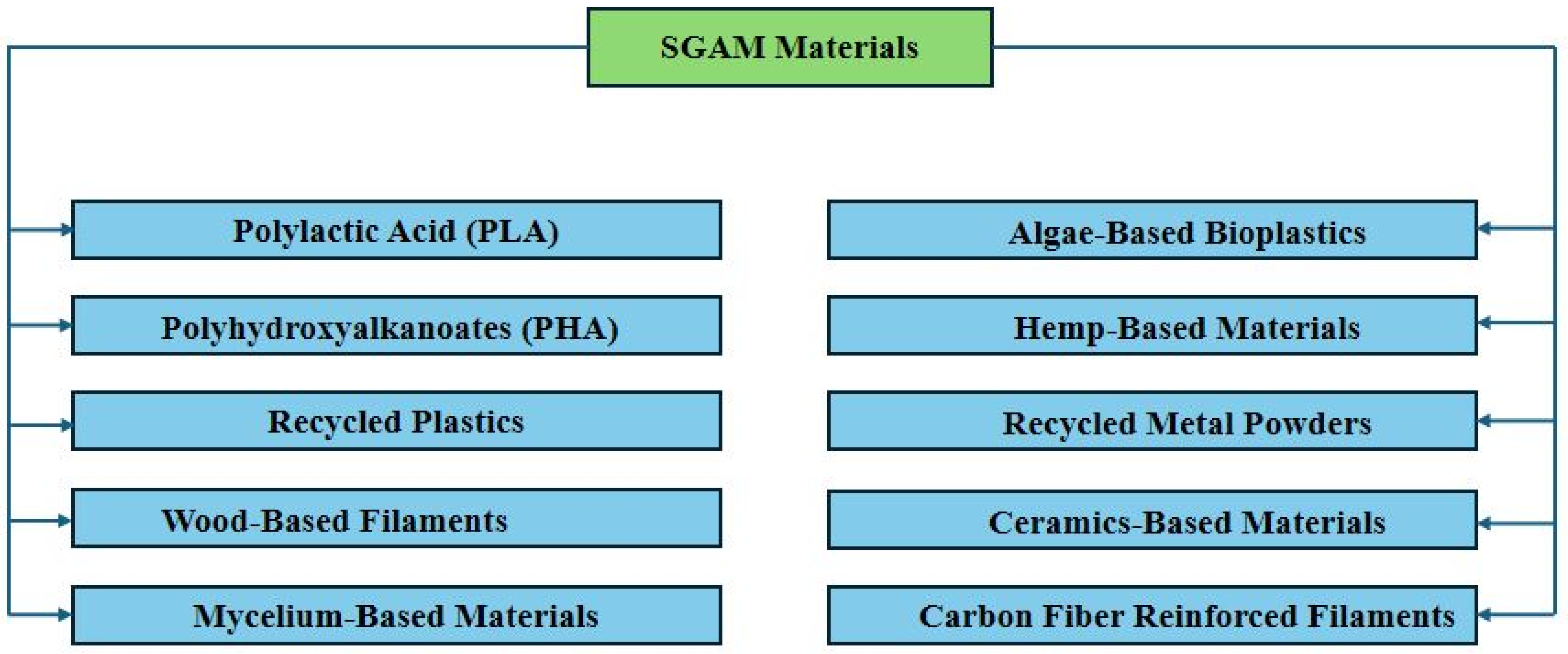
Sustainable green additive manufacturing (SGAM) leverages these benefits but also emphasizes using truly sustainable materials. Such materials should be renewable, recyclable, and non-toxic to minimize lifecycle energy use and emissions [4,5]. The goal of SGAM is to use environmentally friendly supplies and techniques to lessen the way production influences the environment. It helps designers and architects create by using biodegradable, bio-based, and recycled materials relevant to the circular economy and less waste. In recent years many researchers have used different types of materials, which are shown in Figure 2. As Fused Deposition Modeling (FDM) requires an easy-to-use, biodegradable material, Polylactic Acid (PLA) made from corn starch or sugarcane is often preferred. Biomaterials known as polyhydroxyalkanoates (PHAs) are created by microbial fermentation and can be used in medicine and agriculture and for making packaging because they are both degradable and safe [6]. Several prominent 3D printing companies, such as Ultimaker, Filamentive, and Reflow, have adopted the use of recycled plastics, including polyethylene terephthalate (PET), high-density polyethylene (HDPE), and Acrylonitrile Butadiene Styrene (ABS) to minimize plastic waste, but they could lower the print quality a little. Nowadays, biodegradable wood/polymer composite filaments, with bamboo or cork added to PLA, are used for home décor items like sculptures and clear architectural models [7]. Since organically grown mycelium materials are lighter than many alternatives and are insulating and fire-resistant, they are often used for packaging and furniture [8]. With algae-based bioplastics, we have another creative choice; these grow rapidly, use little energy, and absorb CO2, so they fit well in sustainable packaging [9]. Tough natural fibers from hemp serve as the key component of composites made with plastics. Owing to its eco-friendly properties, including carbon sequestration and thermal insulation, industrial hemp is gaining attention as a sustainable material for applications such as hempcrete in construction and potentially in lightweight composite materials for vehicles [10]. Eco-friendly additive metal manufacturing in aerospace and tooling uses aluminum and titanium powder remnants [11]. Dental materials made from zirconia and alumina are durable, resist corrosion, and are commonly produced from recycled materials. Carbon fiber reinforcement of filaments made from reused carbon fibers in PLA add strength and are preferred in the aerospace, automotive, and sports industries [12,13].
Green additive manufacturing is very promising in terms of minimizing the environmental footprint by using materials efficiently, enabling significant design changes, and supporting local manufacturing [14]. Green materials such as biodegradable or recyclable polymers and metals are still scarce and not applicable to industrial scale. While many studies focus on specific aspects of 3D printing, a broader perspective is necessary to understand its role in sustainable manufacturing. Additive manufacturing combines design flexibility, material efficiency, and environmental considerations, yet often reveals a gap between the promise of green materials and their real-world performance. Although the existing literature is full of exciting ideas for biodegradable or recycled materials, it falls short on addressing the tough engineering challenges. It highlights that it is one thing to invent an eco-friendly plastic, but it is another to make it strong, affordable, and compatible with today’s machines. This central problem leading to key gaps needs to be emphasized. On the research front, advancing stronger and more innovative green materials, along with developing more intelligent software to manage them, is essential. From a practical perspective, we also need to address the challenges of high costs, inconsistent product quality, and sluggish production speeds that currently hinder the widespread adoption of sustainable solutions.
The scope of this review is to serve as a clear and honest roadmap with a layout of the current state of all major 3D printing methods and assessment of their green potential. For 3D printing to become truly sustainable, these should involve creating stronger and more affordable green materials, developing less-energy-intensive methods to produce high-quality parts, and establishing a standard way to measure the full environmental footprint beyond just the printing process. These steps are critical to making sustainable manufacturing practical, cost-effective, and scalable for broader industrial adoption. By clearly defining the hurdles in research, industry, and even policy, they aim to guide engineers, business leaders, and innovators toward closing these gaps and turning the promise of sustainable manufacturing into a widespread reality.
The structure of this work is organized to comprehensively address the landscape of SGAM. Section 2 introduces key technologies applied in SGAM, including Fused Deposition Modeling (FDM), Selective Laser Sintering (SLS), Direct Ink Writing (DIW), and other emerging low-energy and hybrid fabrication techniques. These are examined in conjunction with the application of biodegradable and recycled materials, highlighting advancements in process integration. Section 3 focuses on current practices adopted in SGAM, such as the use of sustainable feedstocks, recycling of materials, design for sustainability, lifecycle assessment, and waste minimization strategies. Section 4 discusses critical challenges, including environmental constraints, material compatibility, process scalability, and mechanical performance limitations. Section 5 outlines future directions, emphasizing the development of novel eco-friendly materials, improved recycling techniques, and strategies for integrating sustainable practices more effectively within AM workflows. Finally, Section 6 summarizes the role of materials and predictive models in shaping the future of SGAM, underscoring their potential to enable more efficient, environmentally responsible manufacturing solutions.

2. Sustainable Green Additive Manufacturing Technologies

SGAM aims to dramatically reduce AM’s environmental footprint across the entire product lifecycle. By emphasizing circular resource loops and efficient waste management, SGAM improves material efficiency, lowers energy use and transport, and extends product lifetimes [15]. This challenges the traditional AM focus on rapid prototyping and complex geometries, shifting it toward avoiding waste from base materials. An in-depth exploration of key additive manufacturing technologies used in SGAM are discussed as follows.

2.1. Materials Extrusion

Using AM, materials are built in layers by moving through a nozzle or extrusion head in the material extrusion process [16]. Out of all the AM techniques, FDM, DIW and Concrete 3D Printing are part of the material extrusion process, designed for different sets of materials and purpose.

2.1.1. Fused Deposition Modeling (FDM)

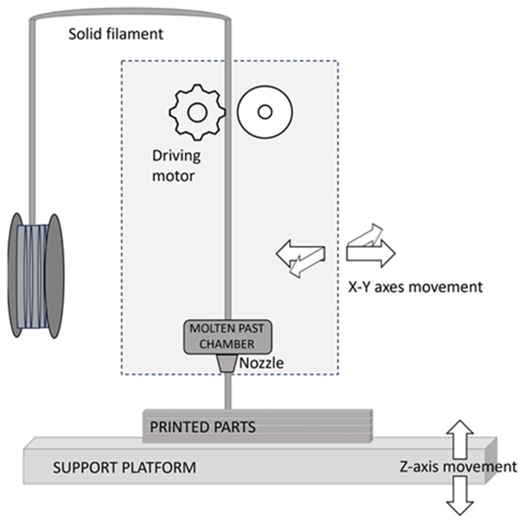
FDM is a standard technique in AM where layers of plastic are built one over the other to make three-dimensional objects. Proper print orientation and raster angles are chosen at the beginning to ensure stresses are reduced and make the structure stronger, which is shown in Figure 3. Most FDM printers are built with a build platform, an extrusion head, and a filament feeding system. For thermoplastic filaments such as PLA, ABS, or polyethylene terephthalate glycol (PETG), the process involves melting them in a heated nozzle at a temperature from 190 °C to 230 °C [17]. Once the material is molten, it is pushed through the nozzle and placed on the build platform along a set path to make each layer of the object. Sometimes, additional material is extruded at the same time to hold up complicated and overhanging parts. Usually, these supports are created so that they are simple to take off after printing, via mechanical methods or dissolving, depending on the material. Because the extrusion head can move on the X, Y, and Z axes, building intricate designs is made possible. After a layer is added and cools, it becomes solid and sticks to the layer underneath. The work continues in this way until the complete object is created. Removal of support structures and polishing may be part of the post-processing step to enhance the appearance and working properties. Many value FDM for being affordable, simple to use, and able to produce durable items that can be used for testing or finished articles [18]. FDM is an affordable, user-friendly, and versatile 3D printing technology ideal for rapid prototyping and producing functional parts from a wide range of materials.
Materials Used in FDM: The versatility of FDM technology is largely enabled by the wide array of thermoplastic filaments it can use. Usually, hobbyists print with PLA (Polylactic Acid), because it is simple to print and breaks down naturally, so it is most suitable for starting out and general workpieces, though people also like ABS (Acrylonitrile Butadiene Styrene) for tougher and temperature-resistant 3D prints. Additionally, PETG is well-known because it offers strength and durability and is easy to print with [19]. As well, nylon is available in FDM for its super toughness and resistance to wear, PC for outstanding strength and the ability to handle heat, and ASA for its good performance in the sun and outdoors [20].

2.1.2. Direct Ink Writing (DIW)

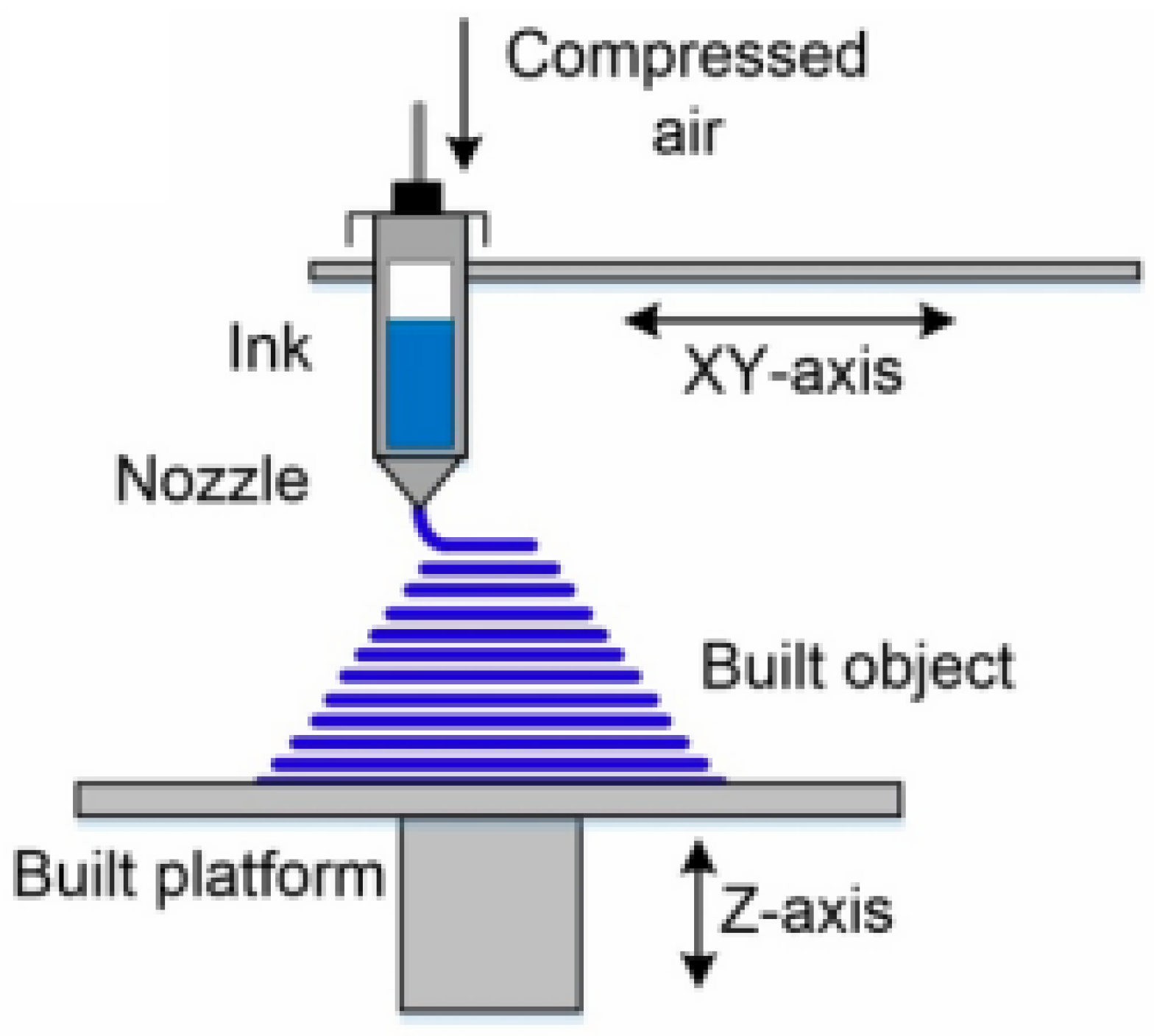
3D objects are made by DIW, where ink is extruded through a tiny nozzle and hardens, as shown in Figure 4. First, a 3D model is made on a computer; then, it is cut into layers. After that, the nozzle moves along the prescribed direction for each layer as an applied force pushes ink out at the desired rate. The basic feature of DIW is the rheology of the ink; it should flow flawlessly when under pressure in the nozzle and rapidly solidify once discharged to ensure every section stays in place for the following layer [21]. 3D printing with biomaterials can be used for many applications since the ink might be ceramic slurries, hydrogels, silicone elastomers, polymers, or composed of special fillers. In most cases, after 3D printing is complete, drying, UV curing, or a furnace-sintering process is needed to ensure that the part reaches its final desired form. DIW is a highly adaptable 3D printing technique that uses a vast range of materials, including sensitive biological and electronic components, to create complex, multi-material, and functionally graded objects in a single process [22].
Materials Used in DIW: The materials that can be used in DIW are very diverse, depending more on their viscosity than their chemical structure. Printable inks typically have viscosities ranging from about 100 mPa·s (0.1 Pa·s) up to 1,000,000 mPa·s (1000 Pa·s) depending on composition, nozzle size, and application [23]. It is most important that the material turns into sticky “ink” after being processed, so it retains its shape once pressed out. Suspending alumina, zirconia, or silica particles in a binder, then letting the mixture set as ceramic slurry, is the beginning of making strong ceramic products by sintering [24]. Polymer and elastomer inks, for example, silicones, epoxies, and polyurethanes, are applied to develop soft and flexible robot parts. For tissue engineering and bioprinting, things such as alginate, gelatin, and hyaluronic acid are used as hydrogels in biomedicine [22]. One significant type is composite ink, where a polymer is mixed with useful components to make substances with extra features; for example, electronics have inks containing silver nanoparticles, and composites for structural applications may contain carbon fiber.

2.1.3. Concrete 3D Printing

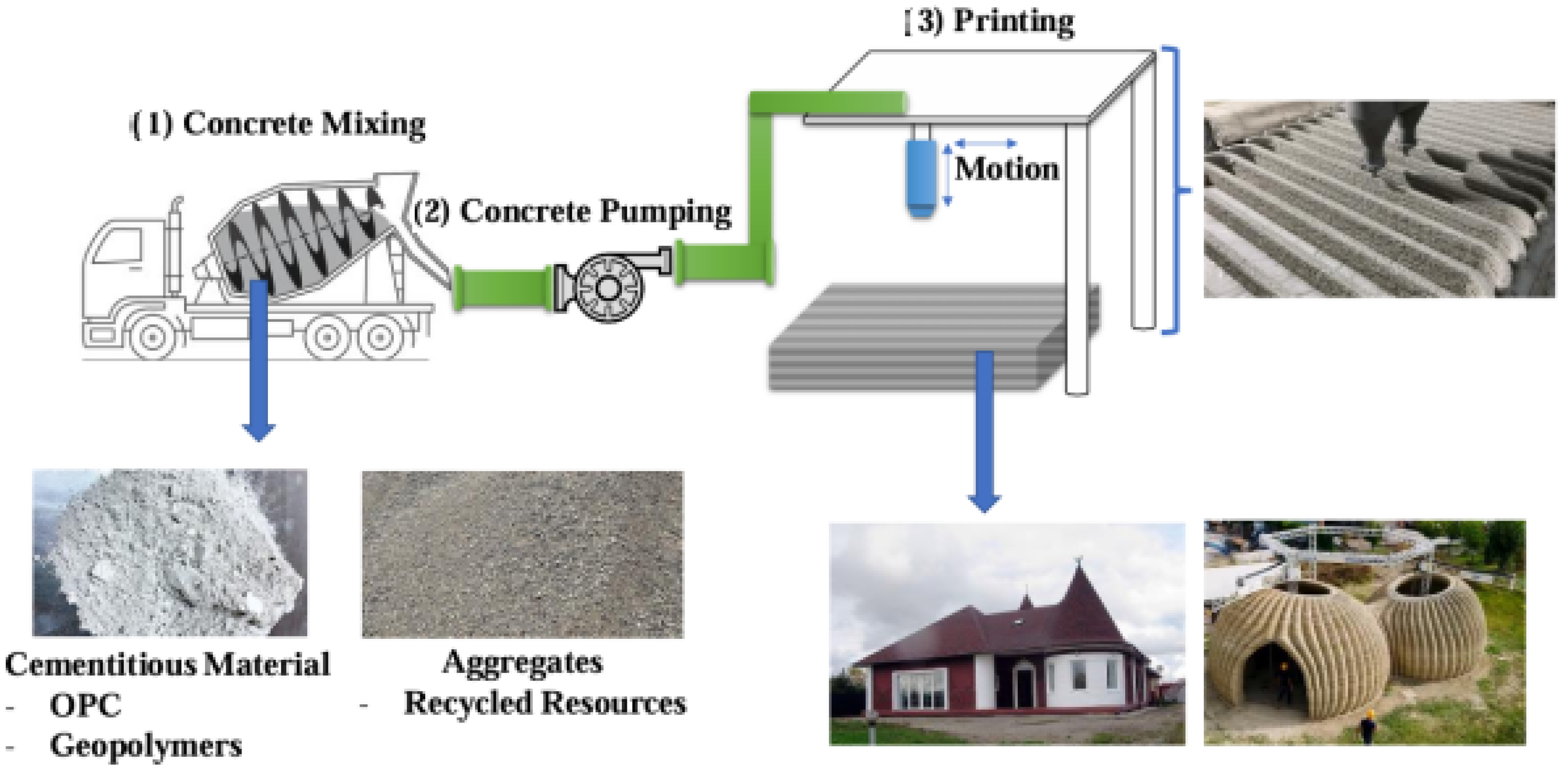
Concrete 3D Printing is used to make large structures by depositing concrete layer by layer, which is shown in Figure 5. The method initiates with the digital design of a three-dimensional (3D) model using computer-aided design (CAD) software, followed by its segmentation into discrete cross-sectional layers through a slicing algorithm. Programmers guide a large robotic system by using either a gantry system that goes above the construction space or a multi-axis arm to follow along the paths of each layer. Through the hose in the pump system, the custom concrete mixture is sent to the printhead for continuous extrusion. The main requirement for the concrete is that it should flow out easily in the pump and still be thick enough to hold its form and support the load as soon as it is poured. The workers keep layering the walls and structural parts from the ground, and no formwork is needed [25]. It is a construction method that uses a large robotic system to extrude a specialized, quick-setting concrete OPC (ordinary Portland cement) in successive layers based on a sliced digital model.
A critical factor in 3D concrete printing is balancing pumpability, the ability of the concrete to flow smoothly through pumps and hoses, with buildability, meaning the extruded concrete must be stiff enough to hold its shape and support successive layers without deformation. To achieve this, printable concrete mixtures are carefully formulated to avoid coarse aggregates that could clog nozzles and often include chemical additives such as superplasticizers and viscosity-modifying agents. The concrete typically exhibits thixotropic behavior, where its viscosity decreases under shear during pumping but rapidly rebuilds afterward to maintain shape. Additionally, fiber reinforcements such as glass, steel, basalt, or polymer fibers are sometimes incorporated to improve mechanical strength and crack resistance, supporting the structural integrity of printed elements [26].
Materials Used in Concrete 3D Printing: Concrete 3D Printing uses a custom, specially made mortar rather than common ready-to-use concrete. It is important to balance the ability of the mix to extrude into shape and the strength it gains right after being deposited. Generally, Portland cement is used as the binder, together with sand, and the use of gravel is avoided so it does not block the nozzle. It is mainly the advanced application of chemical additives that makes concrete innovative. These substances are important because they allow an easier time when pouring the mix, lower the time it takes for each layer to cure, stop the mix from hardening in the machinery, and create the perfect consistency. For stronger concrete, fibers made from glass, steel, basalt, or polymer often are mixed directly into the product [27].

2.2. Vat Polymerization

Different types of techniques are used for vat polymerization, like stereolithography (SLA), Digital Light Processing (DLP), and two-photon polymerization (2PP), where a vat is a container or reservoir that holds the liquid photopolymer resin used in the printing process. The vat photopolymerization process uses liquid resins, and recent advances have produced bio-based or recyclable photopolymers. In contrast, traditional petroleum-derived resins emit volatile organic compounds (VOCs) during printing and curing, making recycling and safe operation challenging. The SLA process uses a focused UV laser to cure liquid resin layer by layer. This yields exceptionally precise parts with smooth finishes, which is why SLA is popular for detailed prototypes, molds, medical models, and jewelry parts [28]. However, SLA accepts only a limited range of materials, and parts typically require post-curing and cleaning steps. Despite these limitations, SLA continues to be valued for its precision and part quality [29]. In addition, 2PP and DLP use LEDs and oxygen projectors successively.

2.2.1. Stereolithography (SLA)

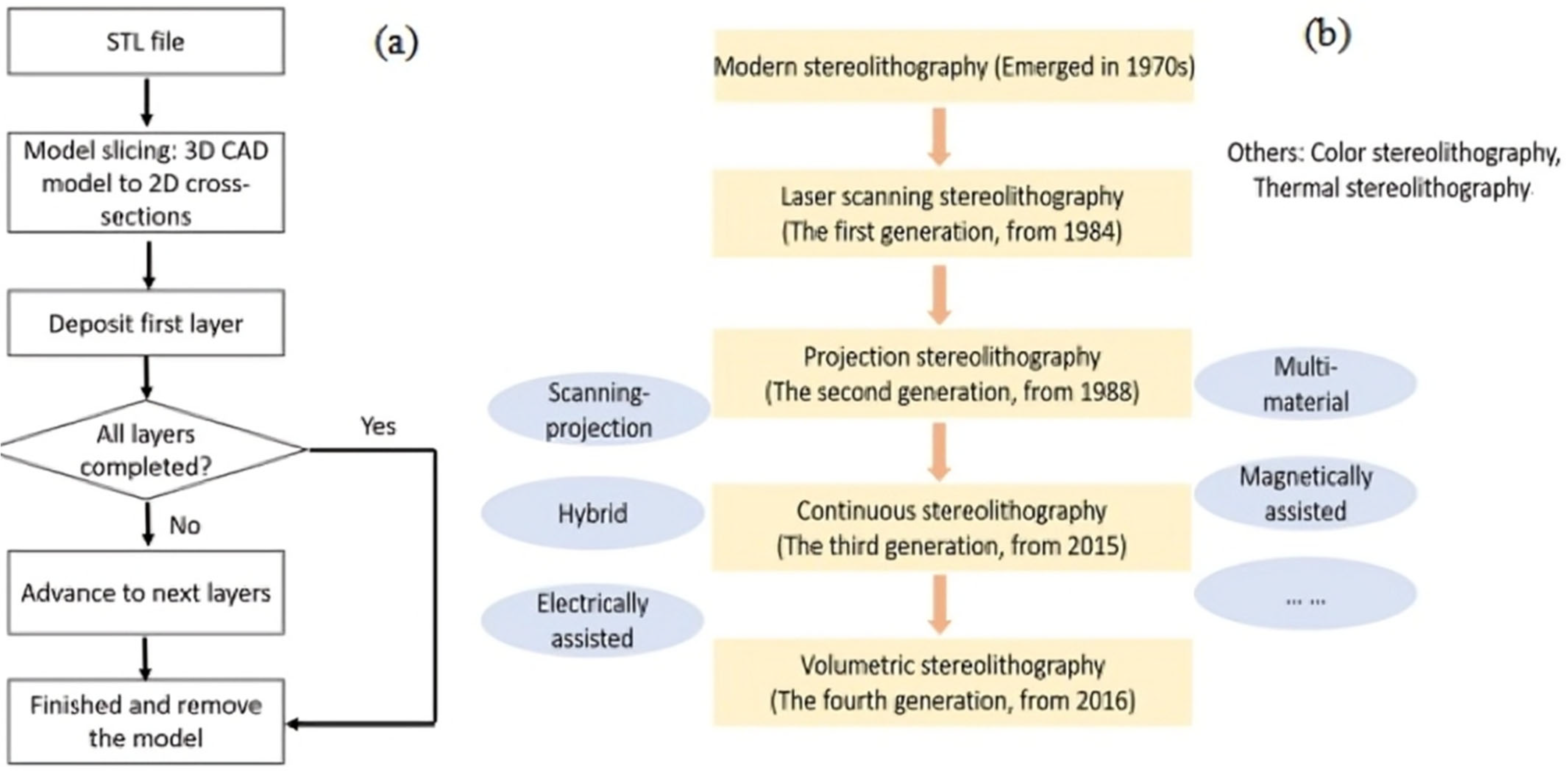
SLA relies on selective solidification through photopolymerization of a liquid resin to form 3D objects. Its process flow chart is shown in Figure 6. The process starts with designing a 3D CAD model, exporting it—commonly in STL format—to represent the surface geometry. Specialized slicing software then converts this model into a series of thin 2D layers (slices), generating machine instructions (e.g., G-code) for the printer to follow. The vat contains a resin composed of monomers, oligomers, and photoinitiators, which together allow the photopolymerization process to occur upon exposure to a specific wavelength of light. A focused ultraviolet (UV) light beam selectively scans the surface of the resin, tracing the geometry of a single, two-dimensional (2D), cross-sectional layer of the 3D model. The UV lights initiate a photochemical reaction that triggers polymerization, causing the exposed regions of the liquid resin to solidify and form a cross-linked polymer network. After making one layer, the platform is lifted by another layer’s thickness, and the building process continues one layer at a time until the complete three-dimensional object is formed. SLA is a highly accurate and versatile 3D printing technology that excels at creating detailed models and has evolved to become faster, more affordable, and compatible with a wider range of materials [29].
Materials Used in SLA: In SLA, photosensitive liquid resins are employed, which undergo solidification upon exposure to ultraviolet (UV) light through a photopolymerization reaction. These resins are mostly held in a bath, where they are made up of liquid monomers, oligomers, and photoinitiators. Although this review does not discuss certain resins, it points out that the technology uses a number of materials that can be applied in many fields [30]. Besides materials, this paper looks at technologies that widen the scope of available resources. As an illustration, multi-material stereolithography means that two or three materials may be mixed and printed into one finished 3D object.

2.2.2. Two-Photon Polymerization

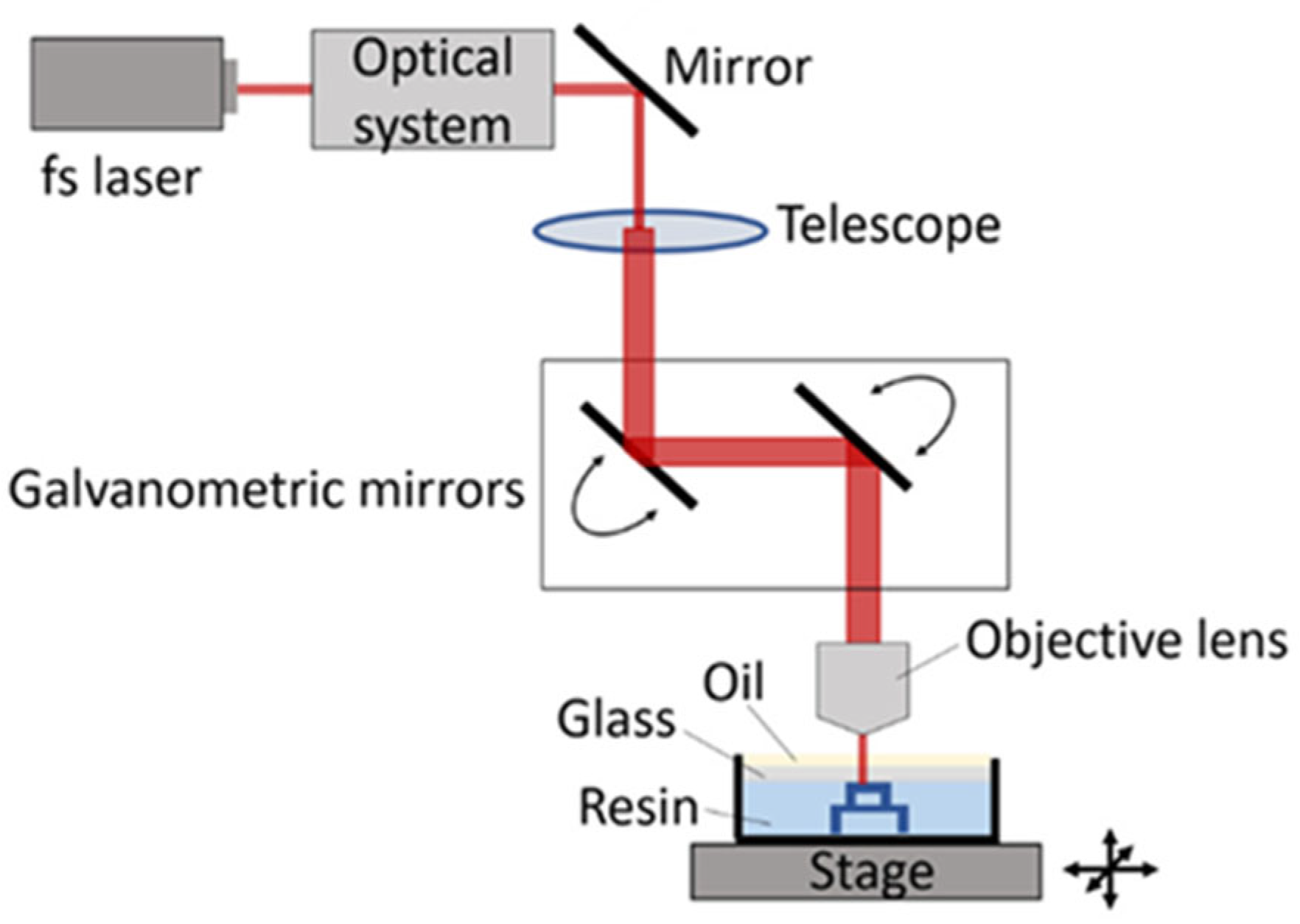
Two-photon polymerization (2PP) is performed through direct laser writing based on non-linear two-photon absorption, with the underlying operating principle illustrated in Figure 7. A femtosecond-pulsed laser is used to send very short pulses of light through a high-power microscope lens into liquid photoresponsive resin. Unlike when a single photon is absorbed, this process occurs only at the laser’s focus, since there are more photons packed at this point, and thus polymerization happens within a tiny voxel. With a galvo mirror system, the laser’s focal point is scanned in 2D, and the Z-position is adjusted by off-axis piezoelectric stages. The solid structure is written layer by layer in the resin, because the laser is precisely focused on different places, ensuring very high detail in every part of the object [29]. 2PP provides the highest resolution of any 3D printing technology, enabling the rapid fabrication of complex microstructures with features down to the nanometer scale [31].
Materials Used in 2PP: All materials used in two-photon polymerization (2PP) are photosensitive resins that undergo localized solidification due to polymerization upon interaction with the focused femtosecond laser beam. Most commercial resins obtained through mass polymerization are made up of acrylate or epoxy chemicals. The use of commercial resins such as IP-L 780 and IP-Dip in the Nanoscribe IP-series enables the fabrication of high-resolution polyacrylate microstructures [32]. In addition to these well-known acrylate-based materials, newer soft resins like IP-PDMS are also being explored for creating flexible structures with properties similar to polydimethylsiloxane (PDMS) [33].

2.2.3. Direct Light Processing (DLP)

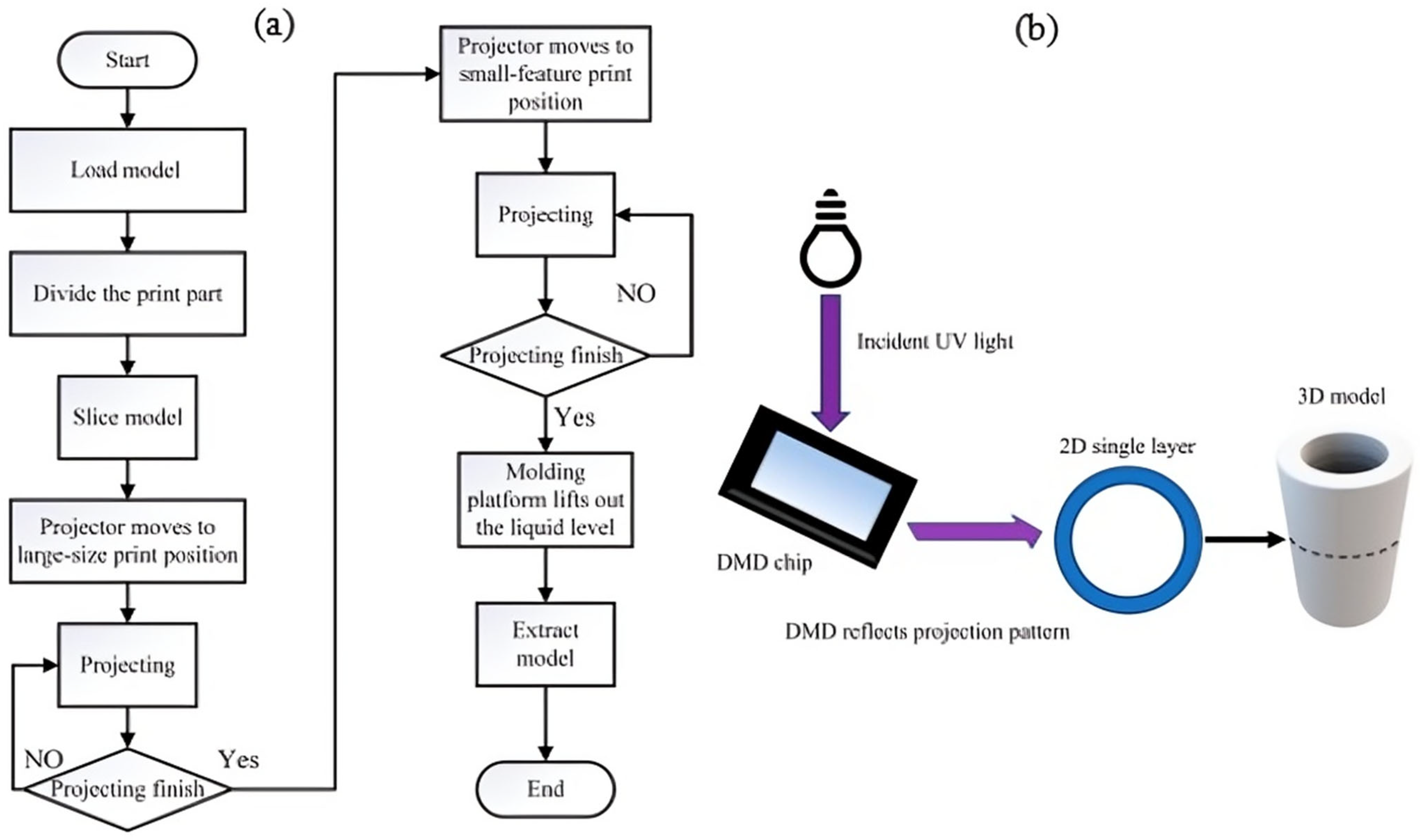
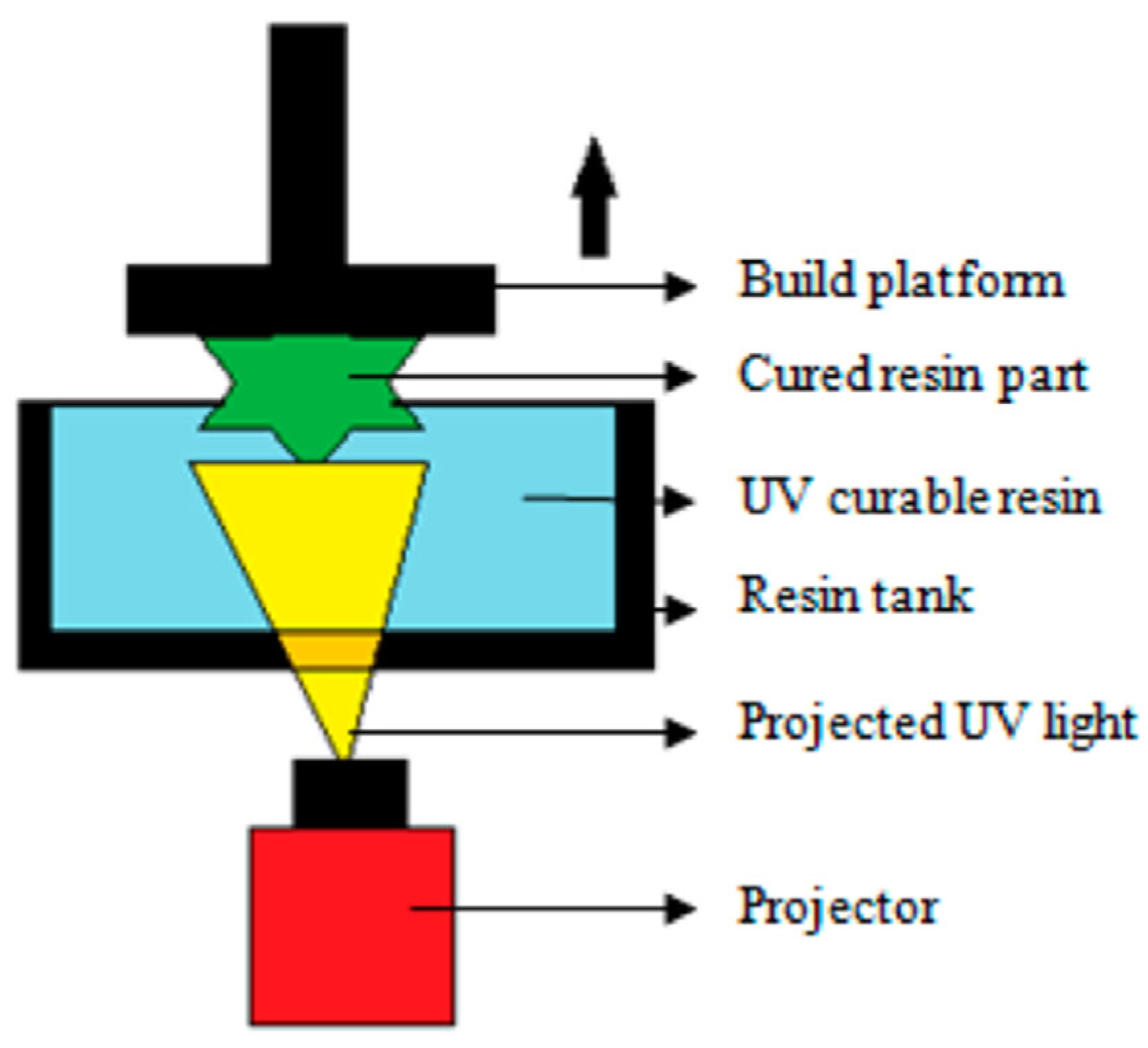
DLP 3D printing is basically a technique that relies on forming materials through photochemical reactions which is portrayed in Figure 8. Essentially, a typical DLP printer is made up of a movable projector, a platform to print, and a sensitive chemical for curing images. This device relies on a Digital Micromirror Device (DMD), which is a chip containing thousands (or millions) of tiny mirrors that can individually tilt to direct light. As a result, we obtain a field of pixelated light that is arranged in patterns. Light is guided through the optical tools and lands onto the spot between the liquid precursor and the substrate. When light hits the precursor, it starts a chemical response that forms a solid layer with the required form. After the first layer is set, the platform moves, and more layers are printed in sequence to complete the whole 3D object [34]. Recent advancements in continuous printing and integral lithography enable the faster, smoother, and more precise fabrication of large-scale microarchitectures.
Materials Used in DLP: Scientists have studied acrylates, epoxies, and thiolene systems the most among photopolymers. The advent of new photochemical processes has permitted the production of better and more valuable materials. Examples include alkylated GelAGE materials, used for building networks that break down, and DNA hydrogels (D-gel), made to adapt their shapes [35]. Also, hybrid resins made from mixtures of acrylates, epoxies, and monomers with different water-likeness properties are used for making multi-responsive materials.

2.2.4. Scan, Spin, and Selectively Photocured (3SP)

3SP technology is an advanced form of vat photopolymerization that constructs parts layer by layer within a UV-curable photopolymer resin. As illustrated in Figure 9, the process begins with a submerged build platform positioned just beneath the resin surface. A laser beam, guided by a scanning system, selectively cures the cross-section of each layer. Uniquely, instead of using a mechanical blade to recoat the surface, the vat and build assembly are spun rapidly [36]. This spinning action generates centrifugal force, resulting in an even and thin recoating of resin over the cured layer. The cycle of scanning, curing, spinning, and recoating continues until the part is fully constructed. The spin-based recoating mechanism significantly improves surface quality and printing speed, making 3SP suitable for producing high-resolution parts at scale [37].
Materials Used for 3SP: The 3SP technology uses proprietary UV-curable, photo-polymer resins that are specially designed to be compatible with high-speed systems. These are thermoset liquid resins that cure on complete exposure to the laser and are specifically designed to have particular viscosities and curing characteristics that give optimum results using spin-recoating [39]. The material variety is aimed at different engineering demands and includes several groups. It also has standard resins that imitate the behavior of common thermoplastics such as ABS to use as general-purpose prototyping. There are heavy and tough resins capable of producing parts that will require mechanical forcing. Moreover, specialty products like transparent resins and high-temperature resistance resins are also usual [40].

2.2.5. Continuous Liquid Interface Production (CLIP)

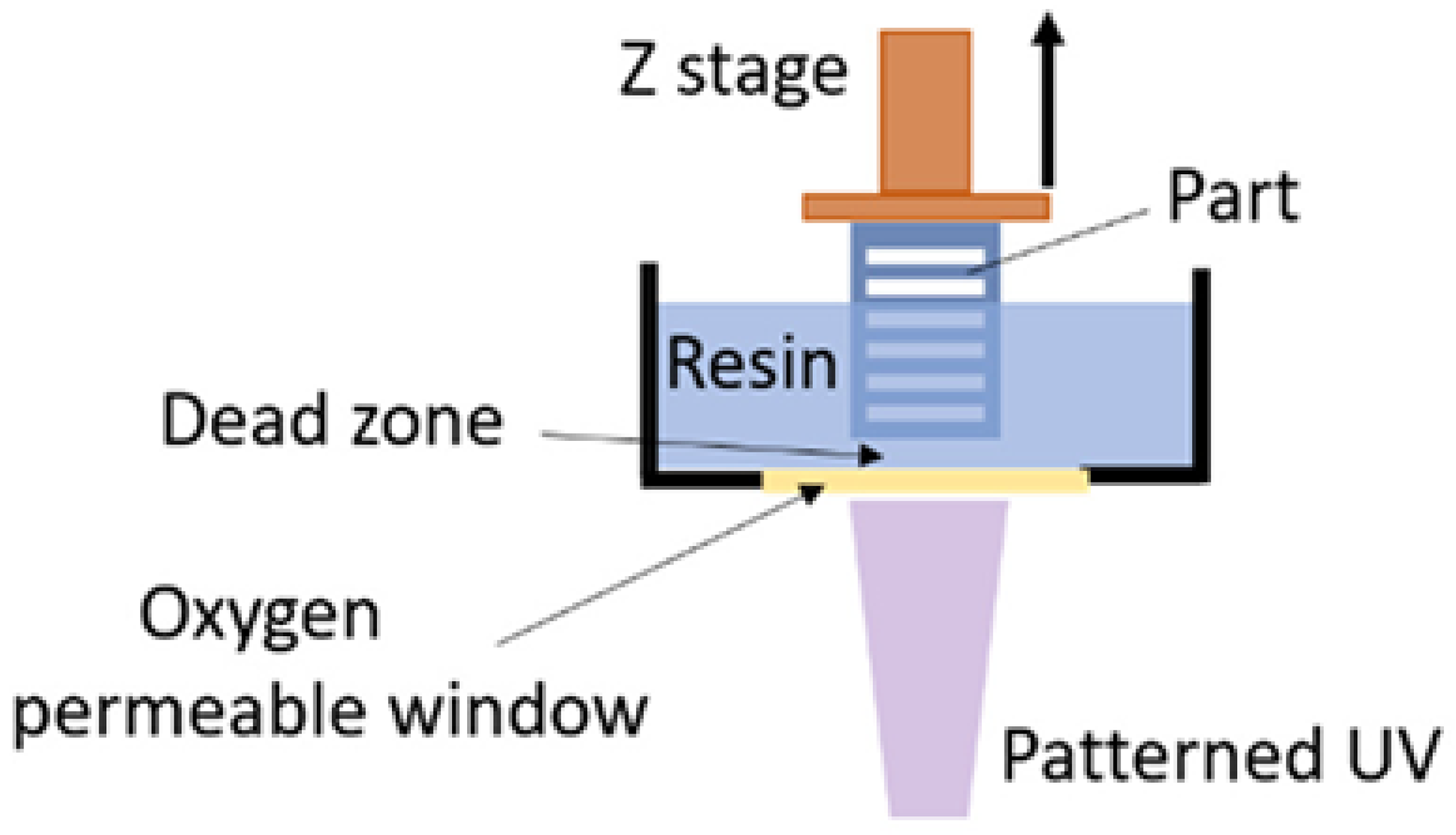
As illustrated in Figure 10, Continuous Liquid Interface Production (CLIP) is a breakthrough vat photopolymerization process that enables parts to be fabricated in a truly continuous manner, rather than layer by layer. The core innovation of CLIP lies in the oxygen-permeable window located at the bottom of the resin vat. This window allows a controlled and continuous flow of oxygen into the resin at the build interface, creating a “dead zone”, a thin layer of uncured liquid resin where photopolymerization is inhibited due to oxygen-induced photo-inhibition [41]. Above this dead zone, a UV light engine projects a rapid sequence of cross-sectional images, initiating photopolymerization just above the inhibited region. As a result, the solid part is continuously drawn upward from the resin pool without the need for mechanical separation after each layer. This eliminates the time-consuming peeling process typically required in traditional layer-by-layer printing techniques [38]. CLIP offers significantly faster build speeds, 25 to 100 times greater than conventional stereolithography, while producing strong, isotropic parts with smooth surface finishes and injection-molded-like quality. Moreover, its ability to form complex, overhanging, or lattice-based geometries without interruptive recoating steps makes it highly suitable for industrial-scale production of functional parts with demanding mechanical requirements [42].
Materials Used for CLIP: The resins used in CLIP are high-tech, high-performance materials designed specifically to be used in the process, and most of them are designed with a dual-cure chemistry. The UV light offers the initial curing in the printing procedure, helping inhale the form of the object. Once the part has been printed, a second bake of a thermal cure is provided in an oven; this bake causes a second chemical reaction to occur [43]. The process of curing happens thermally, which extends the chemical bonds throughout the material, releasing its ready, durable state of engineering excellence [44].

2.2.6. Solid Ground Curing (SGC)

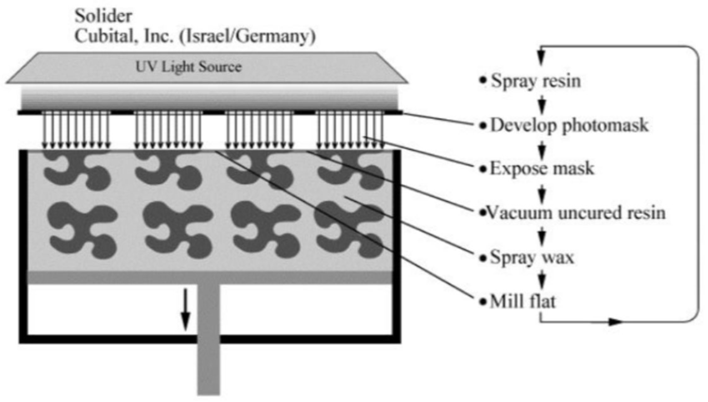
As illustrated in Figure 11, Solid Ground Curing (SGC) is a complex, mask-based vat photopolymerization technique developed to achieve high printing speed and dimensional accuracy. Unlike conventional stereolithography, SGC does not rely on laser scanning. Instead, it creates a full-layer photomask for each cross-section of the object. This is accomplished through a process analogous to photocopying: a glass plate is electrostatically charged, and black toner is selectively deposited to form an opaque mask representing the geometry of the entire layer [45]. This photomask is then positioned above a thin film of UV-curable photopolymer resin spread across the build platform. A high-intensity UV lamp exposes the resin through the transparent portions of the mask, curing the entire layer in a single flash exposure. Areas shielded by the opaque toner remain uncured. Following exposure, the uncured resin is removed, and the voids are filled with molten wax, which quickly solidifies and provides mechanical support for overhanging structures and internal cavities. To ensure uniform layer thickness and surface flatness, each layer undergoes precision milling using a mechanical head that flattens both the cured resin and wax to a controlled height. This cycle of masking, curing, filling, and milling is repeated until the object is fully formed. The final product is embedded in a solid wax block, which is later melted away during post-processing to reveal the finished part [46].
Materials Used for SGC: The SGC process requires three distinct types of materials to function. The first is the build material, which is a UV-curable photopolymer resin, typically an acrylic or epoxy-based liquid, like those used in other vat photopolymerization processes. This material forms the actual final part. The second crucial material is the support material. This is a proprietary, low-melting-point, non-curable wax, such as paraffin or a blend specifically engineered for stability and ease of removal. This molten wax is used to fill all the voids in each layer, solidifying to provide support before being machined flat. In the final post-processing step, this wax is simply melted away to reveal the finished part [47]. The third category of materials is the masking consumables, which include the special black toner and the glass plates used to create the photomask for each layer, though these are part of the process and not the final object.

2.2.7. Daylight Polymer Printing (DPP)

As illustrated in Figure 12, Daylight Polymer Printing (DPP) is a low-cost, simplified variant of vat photopolymerization, closely related to Masked Stereolithography (MSLA). Unlike traditional stereolithography, which uses UV light for curing, DPP employs visible, daylight-spectrum light to initiate polymerization. The core of the system is a standard high-resolution LCD screen, positioned beneath a transparent resin vat floor. This LCD functions as a dynamic photomask, displaying black-and-white images of each cross-sectional layer [48]. During printing, a strip of low-power, broad-spectrum LEDs emits visible light that passes through the LCD screen. White pixels allow light to pass through and cure the resin above them, while black pixels block the light, leaving those regions uncured. This selective exposure solidifies one full layer at a time. After each layer is cured, the build platform elevates, and the process repeats until the entire part is complete [49]. The simplicity of the DPP setup, using off-the-shelf consumer electronics like LCD panels and visible light LEDs, makes it highly cost-effective, easy to maintain, and ideal for entry-level or hobbyist 3D printing. Moreover, the use of visible light allows for safer operation and reduced hardware cost compared to UV-based systems. Despite its low-cost nature, DPP can produce parts with good resolution and surface quality, making it a practical solution for rapid prototyping and educational applications [50].
Materials Used for DPP: DPP material comprises an essential and specific part of system materials. In contrast to common UV resins, DPP needs proprietary liquid photopolymers specially designed to respond to and be hardened by low-intensity visible-spectrum light. The LEDs produce energy referred to as the daylight, which these special photoinitiators react with. Many printer manufacturers, including Photocentric, who first developed the technology, have broad options of these resins to fit various applications [51]. These include firm or hard resins such as Daylight Pro Hard, Daylight High Tensile, and Daylight Pro White, used for high-detail models and prototyping. Tough resins like Daylight Durable Resin and Daylight HighTemp DL400 are designed for functional parts requiring impact resistance and heat tolerance. Flexible resins such as Daylight Flexible DL220 and Daylight Pro Flexible are suitable for models that require elasticity and compressibility [49].

2.3. Powder Bed Fusion (PBF)

The powder bed fusion method deposits a thin layer of powdered material followed by a strong heat beam, selectively fusing the powder to form parts. AM techniques include types called Selective Laser Sintering (SLS), Selective Laser Melting (SLM), and Electron Beam Melting (EBM). Laser energy is used to melt the particles of the polymer powders at a temperature just below the melting point. One can create structural shapes and test models without additional support. Most of the other materials used in PBF are thermoplastics, such as nylon, and often employ plastic threads [52,53]. Conversely, SLM exposes a high-energy laser to longitudinal powders of metals, which eventually creates products that are perfectly solid with satisfactory mechanical characteristics. Since aerospace, medical, and automotive industries require strength, accuracy, and durability, the technique is usually employed by high-performance businesses [54]. The process reduces residual stress and makes components to fit tough compatible purposes. Since the powder bed fusion technology is produced correctly and has precise as well as strong output, it is a critical industrial process in 3D printing [55].

2.3.1. Selective Laser Sintering (SLS)

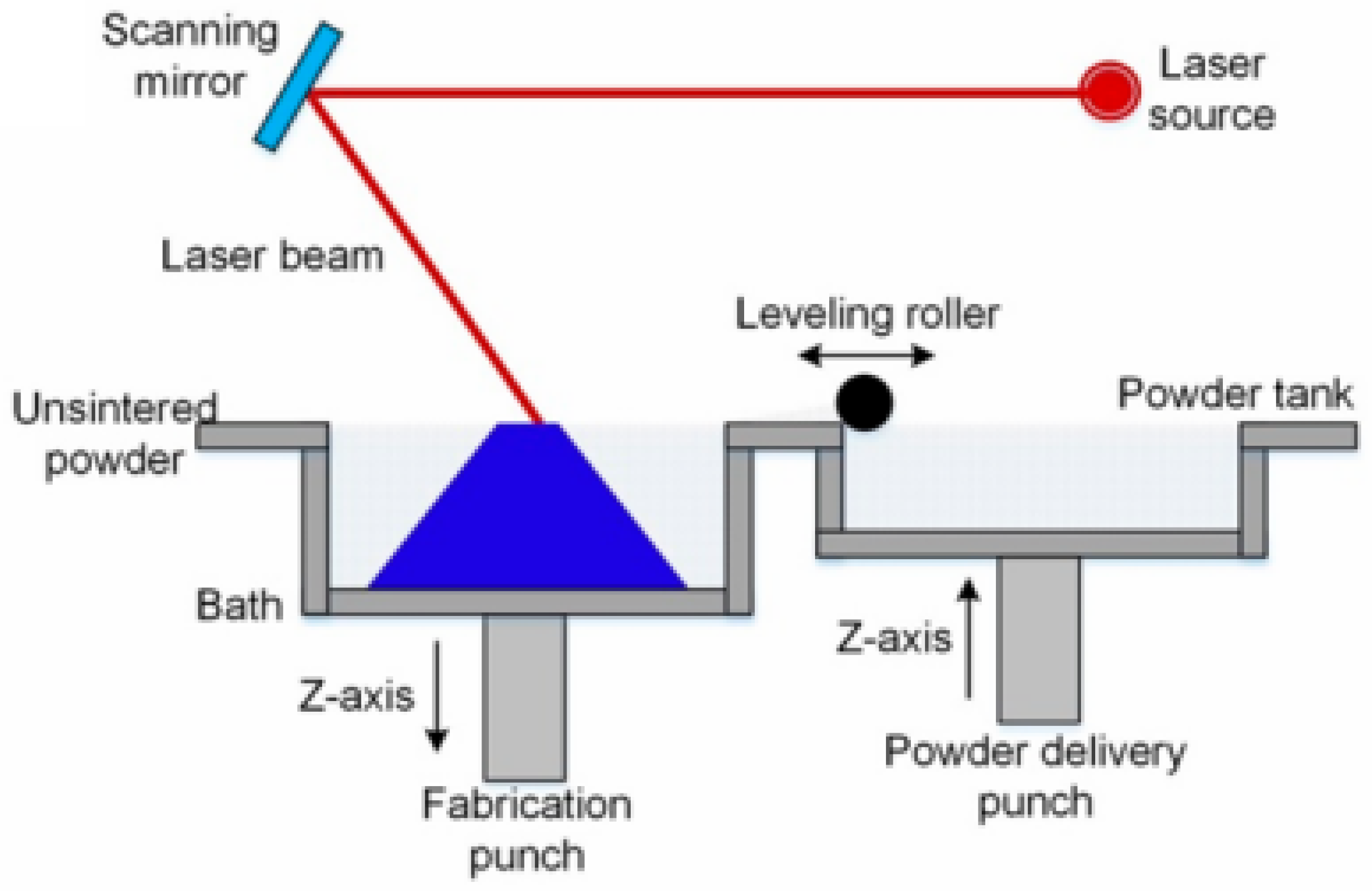
SLS is an AM method that uses lasers to form solid three-dimensional objects from powders. The model turns into 2D layers that are created from the 3D design, which is shown in Figure 13. The machine spreads parts of the powder material using a roller on the build platform. After that, the scanner moves the CO2 or Nd:YAG laser beam along the edges of the first layer on the powder surface [21]. The powder particles are heated by the laser until they stick together and become solid. This paper explains that there are three main ways to achieve the fusion, including solid-state sintering, melting assisted by a liquid phase, and full melting. A new layer of powder is placed after the fabrication piston moves down, and the process is carried out until the entire object is built.
Materials Used in SLS: The most usual polymers are made from both semi-crystalline and amorphous types like biodegradable polycaprolactone (PCL), high-performing polyetheretherketone (PEEK), and natural ones such as cellulose. Ceramic products play a big role, ranging from direct use to products that have polymers mixed in as binders. Some bioactive materials used are calcium silicate, hydroxyapatite (HA), and glass compositions of multiple types [56].

2.3.2. Selective Laser Melting (SLM)

SLM is an AM process that uses a laser to fabricate dense metallic components from a powder bed, as shown in Figure 14. The process begins with a 3D computer-aided design (CAD) file that defines the component’s geometry. Inside the machine, a thin layer of fine metal powder is spread across a build platform. A high-energy laser beam then selectively scans the powder, following the path of the first 2D cross-section of the part [57,58]. The intense energy of the laser melts the powder particles, creating a dynamic molten pool. This pool is governed by complex thermodynamic mechanisms, primarily Marangoni convection, which dictates the heat and mass transfer within the melt. As the laser moves on, this molten pool rapidly solidifies, fusing the particles into a solid layer. The process is repeated layer by layer, with the solidified part gradually being built up from the fused powder. SLM provides an effective and economical method for processing difficult-to-machine materials like Ni-based superalloys into complex, high-density parts with excellent dimensional precision and surface quality [59].
Materials Used in SLM: SLM is a versatile technology capable of processing a wide array of metal powders into dense, high-performance parts. High-performance materials are central to its use, including titanium alloys like Ti6Al4V, which are favored in aerospace and medical applications for their excellent strength-to-weight ratio and biocompatibility [60,61]. For extreme-temperature environments, nickel-based superalloys such as Inconel 718 are the standard for jet engine and turbine components. For industrial applications, stainless and tool steels offer durability and hardness for tooling, while lightweight aluminum alloys are crucial in the automotive and aerospace sectors. Cobalt–chrome alloys are a staple in medical and dental fields for high-wear implants due to their strength and biocompatibility [62].

2.3.3. Cold Spray Additive Manufacturing (CSAM)

CSAM is a solid-state, supersonic deposition method where 3D components are built layer by layer without melting the feedstock material, as shown in Figure 15. At first, fine metal or composite powder particles are increased to supersonic speeds ranging from 500 to 1200 m/s by a heater that strongly pressurizes a gas like nitrogen or helium, and this gas is discharged through a nozzle called a de Laval nozzle [63]. When the un-melted, traveling particles touch the substrate, the impact causes strong movement of atoms. Strong impact on the surface of the metal rids it of oxidation, making fresh, clean metal that strongly connects with the other metal surface. As the ejecta hit the ground in quick succession, each layer sticks to the layer below, creating a hard and solid material layer by layer [64]. By working with metal in its solid form instead of melting it, CSAM quickly builds and repairs parts without the usual heat damage, preserving the material’s original strength while sustainably saving resources [65].
Materials Used in CSAM: Many ductile metals and alloys can be formed by using the CSAM process. It works best with soft and bendable materials such as aluminum, copper, and their alloys, as well as material like stainless steel. This technology can apply hard-to-form materials such as titanium (Ti-6Al-4V) and the superalloy Inconel-718, although, sometimes, it needs post-heat treatment to increase its ductility [67]. Creating metal matrix composites (MMCs) like Ni–Al alloys and also coating surfaces with ceramic or polymer layers are important strengths of CSAM. This paper refers to using high-entropy alloys (HEA) as new materials, emphasizing that the process can cover various types of industry materials [66].

2.3.4. Binder Jetting

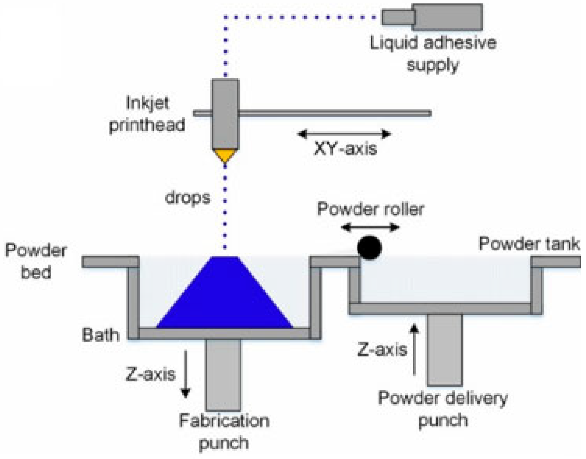
The universal principle of binder jetting is that it is an additive manufacturing process that builds objects by selectively depositing a liquid binding agent onto a bed of powder, which is shown in Figure 16. The process begins by spreading a thin layer of the chosen powder, be it metal, ceramic, sand, or polymer, across a build platform. An inkjet-style print head then travels over the powder, precisely jetting droplets of binder to glue the particles together according to the part’s digital cross-section. The build platform lowers, a new layer of powder is applied, and the cycle repeats. The key difference lies in the post-processing [21]. For metals and ceramics, the fragile green part is placed in a furnace to first burn out the binder and then heat the particles to just below their melting point, causing them to fuse together into a dense, solid object sintering. For sand, the finished mold or core is simply cured to strengthen the binder, as the sand itself does not fuse. For polymers, the brittle part is removed and infiltrated with a secondary material like cyanoacrylate super glue to achieve final strength and color vibrancy [68]. Binder jetting offers exceptional speed, scalability, and support-free design freedom for all materials, while specifically enabling the creation of stress-free metal parts, patternless sand molds, and low-cost, full-color polymer models [69].
Materials Used for Binder Jetting: The materials used in binder jetting always consist of a powder/aggregate and a liquid binder, with a third infiltrate component for polymers. For metal binder jetting, the powders include stainless steels, e.g., 316L, 17-4PH, tool steels, nickel-based superalloys like Inconel, and copper, which are bonded with a polymer agent [70,71]. For ceramic binder jetting, common powders are technical ceramics like alumina, zirconia, and silicon carbide. For sand binder jetting, the aggregates are foundry-grade materials such as silica sand, zircon sand, or chromite sand, which are typically bonded with a furan or phenolic resin. Polymer binder jetting most often uses a gypsum-based powder, bonded with colored CMYK (Cyan, Magenta, Yellow, Key/Black) binders to create full-color parts, which are then strengthened with a cyanoacrylate or epoxy infiltrates [72].

2.4. Material Jetting

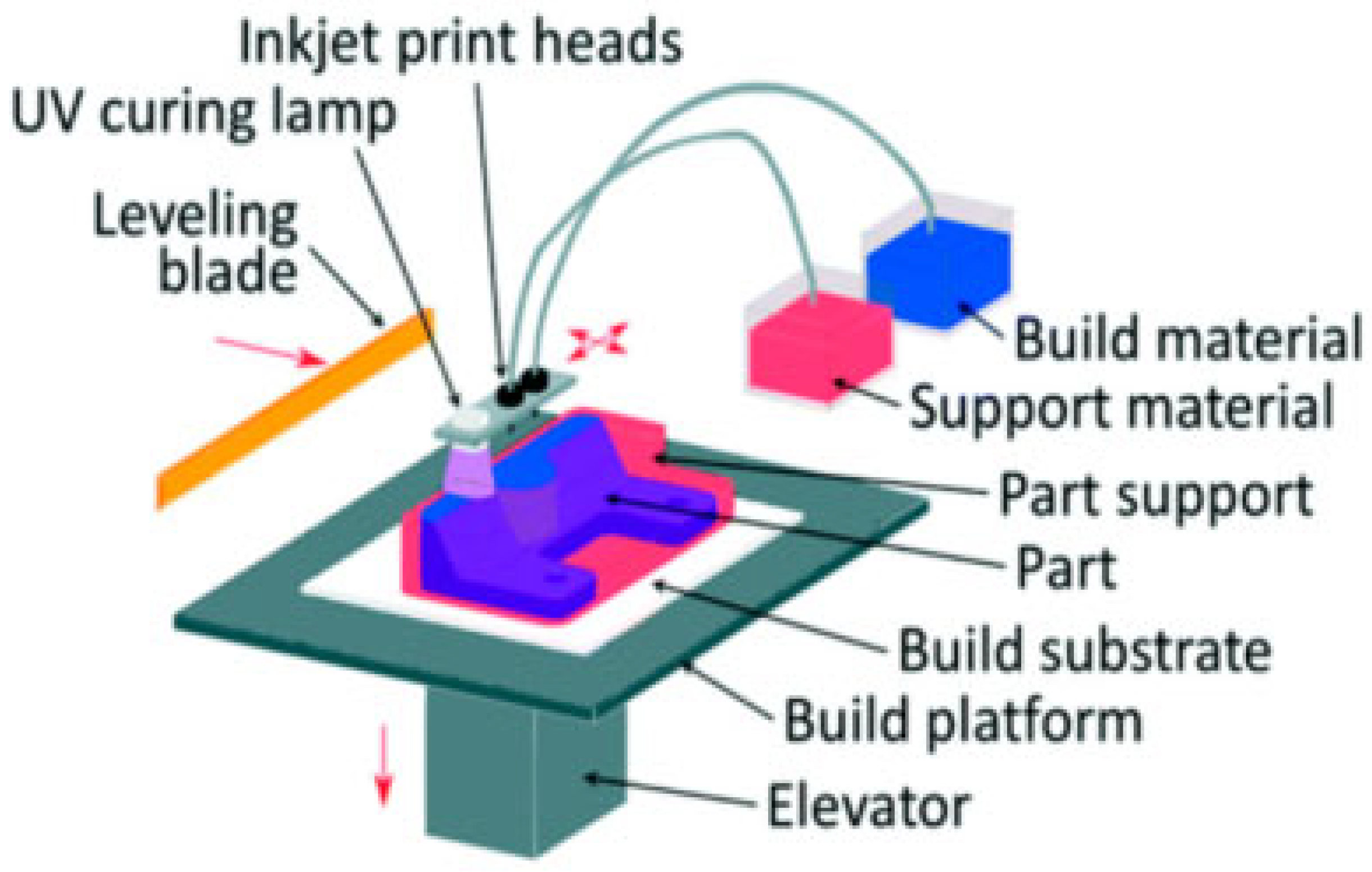
A thin coating of the build material is applied to a substrate, layer by layer, with the droplets being hardened or solidified to manufacture the object in material jetting. It can be seen from the AM classification that PolyJet and nanoparticle (NP) jetting are vital techniques used in this process. In PolyJet technology, the smallness of the photopolymer resin droplets and fast curing with UV light make it possible. As a result, the printing is very detailed, the surface looks polished, and several materials and colors can be used in the same print [73]. It is especially suitable for making prototypes, models that look realistic, items for dentistry, and objects with fine, visual realism. Jets of liquid suspensions containing metal or ceramic nanoparticles are used in NP jetting [74]. Following deposition, the liquid evaporates, and the particles are bonded through sintering to become solid parts. With NP jetting, it is possible to design metal or ceramic parts with fine detail and top precision. One major advantage of material jetting is that it produces objects with impressive accuracy, detailed design, and complex multi-part structures [75].

2.4.1. Multijet Modeling (MJM)

MJM is an AM process that constructs objects by precisely jetting micro-droplets of a liquid photopolymer onto a build platform in a layer-by-layer fashion, shown in Figure 17. Functioning much like a 2D inkjet printer, a print head containing hundreds of nozzles sweeps across the build area, selectively depositing the build material according to the digital cross-section of the 3D model [76]. Simultaneously, a secondary set of nozzles deposits a dissolvable or meltable support material, typically a wax or gel-like substance, to support overhangs and complex geometries. Immediately after the droplets are jetted, a UV lamp attached to the print head passes over the layer, instantly curing and solidifying the photopolymer. The build platform then lowers by one layer’s thickness, and the process repeats until the entire object is complete [77]. MJM delivers exceptionally high-resolution parts with a smooth, injection-molded finish and offers multi-material, multi-color capabilities for creating complex, highly realistic prototypes [78].
Materials Used for MJM: The materials used in MJM are primarily UV-curable liquid photopolymer resins for the build material and a separate substance for support. The build materials are diverse and designed to simulate the properties of various production plastics. These include rigid opaque materials in multiple colors (ABS or Polycarbonate), clear transparent materials, and flexible, rubber-like materials with varying levels of Shore hardness [79]. Specialty resins are also common, such as biocompatible materials for medical applications and castable wax-like resins, which are designed to burn out cleanly for investment casting processes. The support materials are typically wax-based or gel-like compounds that are easy to remove by either melting them in an oven or dissolving them with pressurized water or a solution [80].

2.4.2. Drop-on-Demand (DOD) Jetting

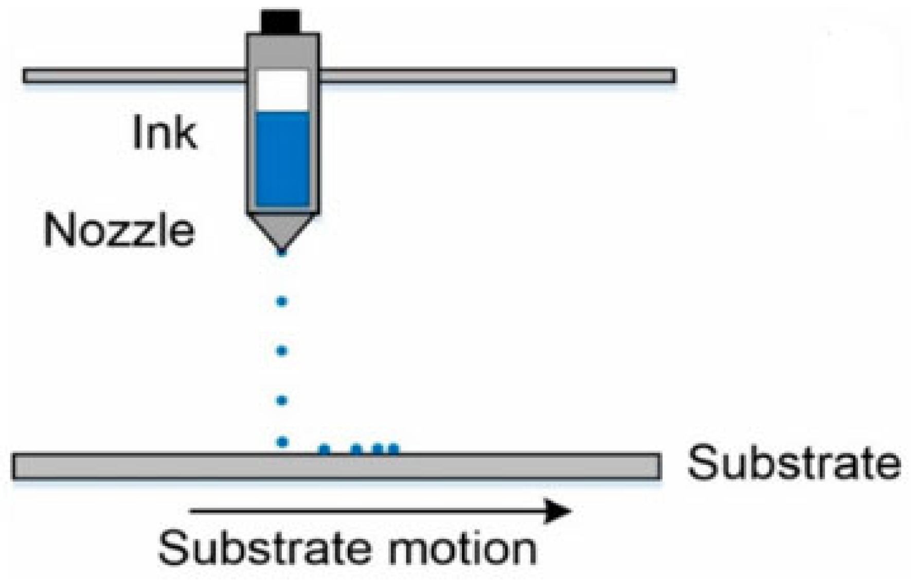
DOD jetting is a digital printing technology where individual droplets of a liquid are precisely ejected from a nozzle only when they are needed to form a pattern or object, as shown in Figure 18. Unlike continuous inkjet systems that produce a constant stream of droplets, DOD systems create pressure pulses within a print head to expel a single droplet at a specific moment. There are two primary mechanisms to achieve this: thermal DOD and piezoelectric DOD. In thermal systems, a tiny resistor rapidly heats a small amount of the liquid, creating a vapor bubble whose expansion forces a droplet out of the nozzle [81]. In piezoelectric systems, a voltage is applied to a piezoelectric crystal, causing it to deform and generate a pressure wave in the fluid chamber, which expels the droplet. In both cases, the process is digitally controlled, allowing for the precise placement of each droplet to build up an image or a 3D layer. DOD jetting offers precise, material-efficient printing, and its ability to safely jet a vast range of sensitive fluids makes it a highly versatile, scalable, and reliable technology for both consumer and industrial applications [21].
Materials Used for DOD Jetting: The range of materials suitable for DOD jetting is exceptionally broad, provided the liquid has the appropriate viscosity, surface tension, and particle size to be jetted reliably. The most common materials are inks, including water-based, solvent-based, and UV-curable inks for graphic arts, textiles, and packaging. In AM (3D printing), the key materials are photopolymers (both rigid and flexible), which are cured by UV light immediately after deposition, and wax-like materials used for creating investment casting patterns [82].

2.4.3. Nanoparticle Jetting

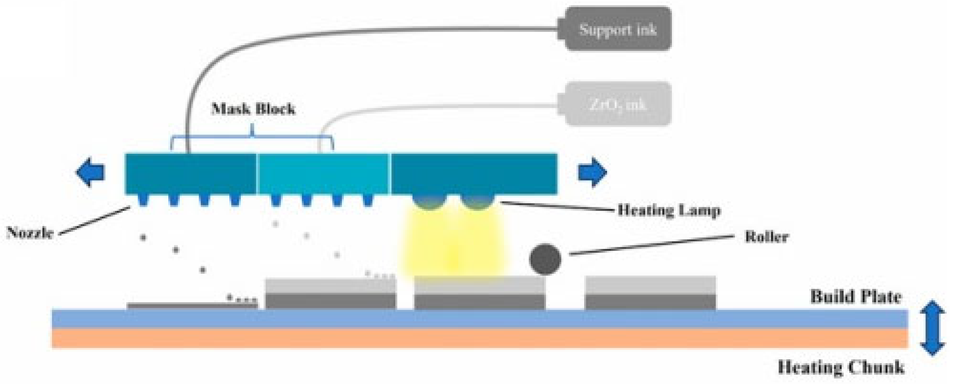
NP jetting is a unique AM process that builds metal or ceramic parts by jetting a liquid containing suspended nanoparticles, shown in Figure 19. The system uses advanced piezoelectric print heads to deposit millions of micro-droplets of this liquid dispersion onto a heated build tray. A key element of the process is that the build chamber is maintained at a high temperature (around 300 °C), which causes the liquid carrier to evaporate almost instantly upon impact [83]. This leaves behind an ultra-thin, densely packed layer of just the nanoparticles. This cycle of jetting and evaporation is repeated layer by layer, meticulously building the object’s geometry. The resulting object, known as a green part, is then removed from the printer and placed into a standard furnace for a final sintering step, where the nanoparticles are heated to just below their melting point, causing them to fuse together into a fully dense, solid object with robust mechanical properties [84]. By building stress-free parts with jetted nano-sized particles, NP jetting delivers unprecedented detail and accuracy, resulting in high-density, isotropic components that rival the quality of Metal Injection Molding.
Materials Used for NP Jetting: The materials used in NP jetting consist of two main components: the structural nanoparticles and the liquid they are suspended in. The nanoparticles themselves determine the final material of the part and include a growing portfolio of high-performance metals and technical ceramics. Common metals include stainless steels, like 316L and 17-4PH, and copper, which are used for their strength, corrosion resistance, and conductivity [85]. The ceramic options include materials like zirconia and alumina, which are valued for their hardness, wear resistance, and biocompatibility. The second component is the proprietary dispersion liquid, which is a low-viscosity fluid engineered to hold the nanoparticles in a stable suspension and evaporate cleanly and completely upon hitting the heated build tray, leaving no residue behind [84].

2.5. Sheet Lamination Process

Sheet lamination is a 3D printing process that builds objects by stacking and bonding layers of material sheets, such as paper, plastic, or metal. A laser or blade cuts the precise shape of each layer before it is bonded to the stack using adhesive, thermal energy, or ultrasonic welding. Once all layers are fused, the excess material is removed to reveal the final, solid part [86].

2.5.1. Ultrasonic Additive Manufacturing (UAM)

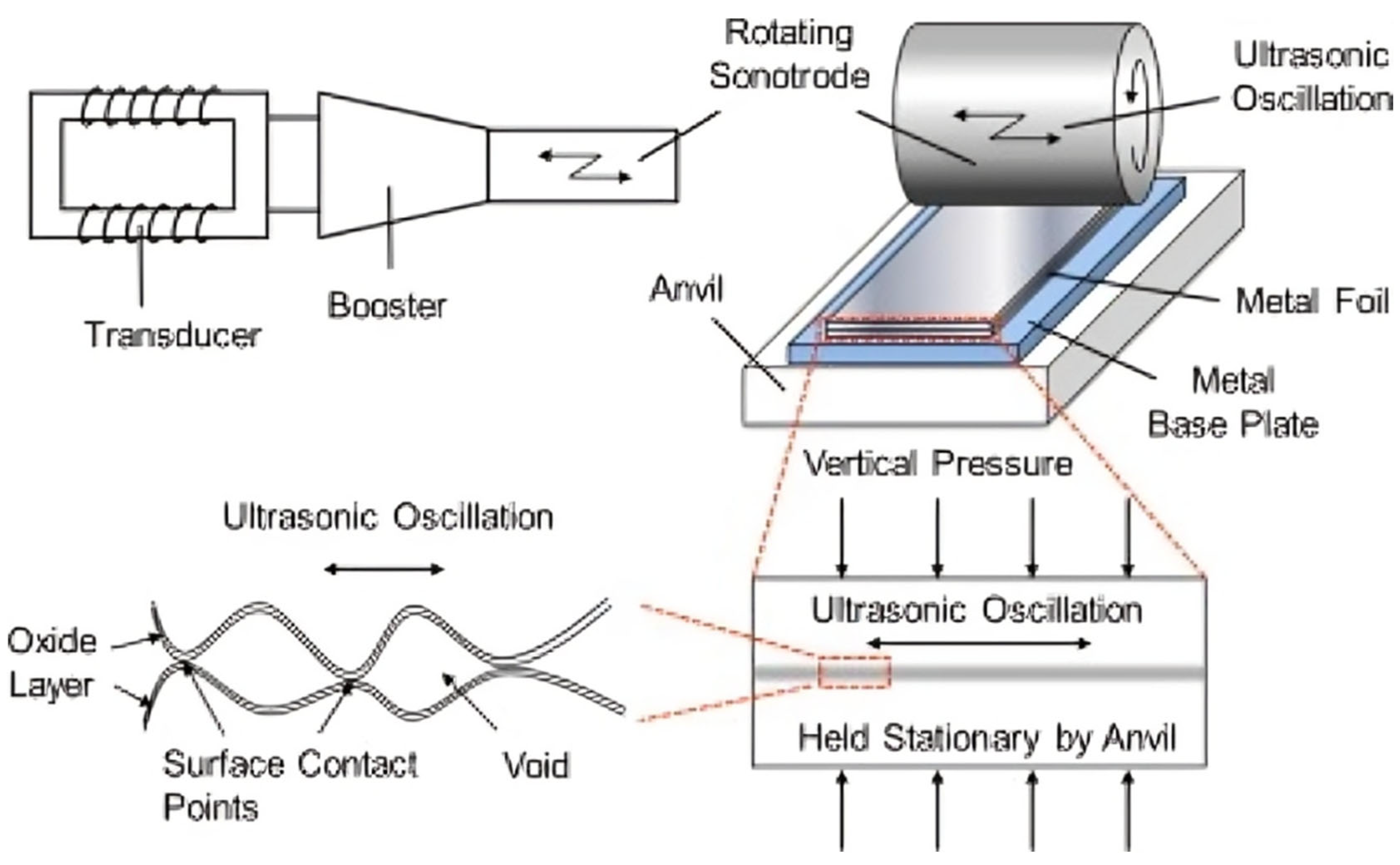
UAM is a novel, low-temperature, solid-state hybrid combining additive sheet lamination with subtractive CNC machining, as shown in Figure 20. The additive component entails the process of incorporating a thin foil or a strip of metal onto a base plate or an earlier deposited layer. This is followed by high frequency ultrasonic pressure and vibrations as a rotating sonontrode moves above the foil. This vibration then destabilizes the surface oxides of the foil and the substrate, resulting in friction and local plastic deformation, permitting a true solid-state metallurgical bond without the metal ever melting [87]. Once one or more layers are deposited, a CNC milling tool incorporated in the same machine is then used to mill the exact shape of the part, mill internal features, or perform a surface finish. This cycle of adding material ultrasonically and removing it with a CNC tool continues until the final, fully dense part is complete [88]. Working at low temperatures without ever melting the metal, UAM avoids heat damage and preserves the material’s original strength, making it possible to embed delicate electronics inside a part or even fuse together metals that cannot normally be welded. UAM is a low-temperature, solid-state process that creates dimensionally stable parts, enabling the unique integration of sensitive electronics, the bonding of dissimilar metals, and high-precision finishing via integrated CNC machining [89].
Materials Used in Ultrasonic Additive Manufacturing: The materials deployed in Ultrasonic Additive Manufacturing should be in the form of thin metal foils or tapes. It is more effective with ductile metals that are softer in nature and allow easier plasticity when ultrasonic energy is applied. The most popular materials are different aluminum alloys (3003, 6061, etc.), copper, and nickel [90]. The major point of strength of the technology is that it can make use of a huge range of dissimilar combinations of materials, that is, bonding of aluminum to copper in areas of thermal management, aluminum to titanium in lightweight structural components, and aluminum to stainless steel. The choice of materials to be embedded into the UAM defines the materials in addition to the structural ones that are offered by UAM [91].

2.5.2. Laminated Object Manufacturing (LOM)

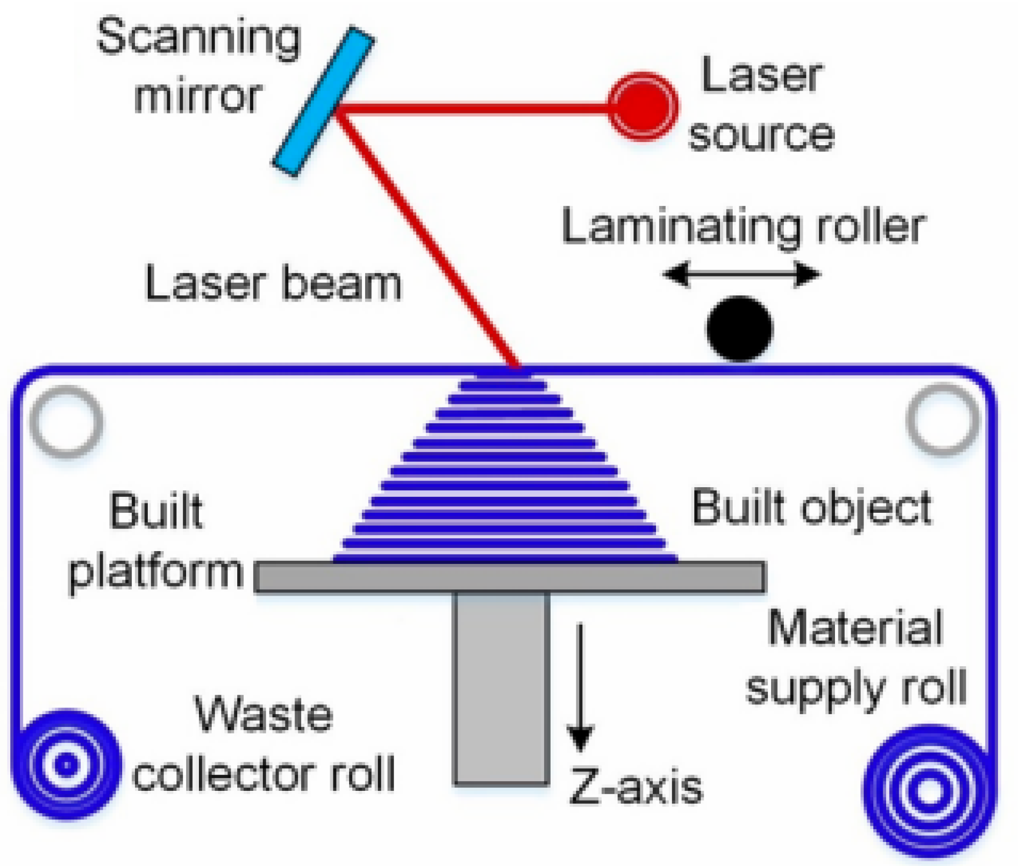
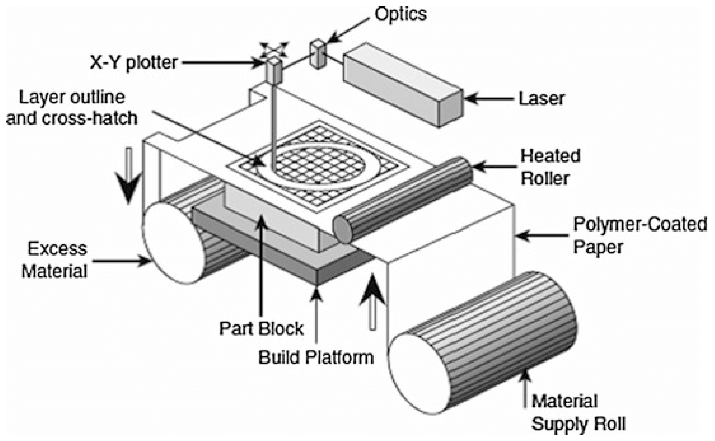
The LOM principle is a sheet laminating production where three-dimensional components are created by layer-by-layer bonding and cutting of sheet materials, as depicted in Figure 21. The raw material is in the form of a roll of material, usually paper, with a heat-activated adhesive applied to the surface. The roll is then fed across a build platform. Thereafter, the sheet receives pressure and heat due to the hot roller, which is subsequently pressed down on the sheet in order to laminate the film on the earlier sheet or on the surface [21]. When the new layer has been cemented, a variety of precision cutting is executed through a computer-controlled laser or blade that cuts the shape of the cross-section of the part to that layer. The laser also forms a cross-hatch pattern of the material that is beyond the part boundary. Then, the build platform descends, another, new piece of material is rolled in, and the laminating and cutting process is repeated until the required height has been attained to produce a block of laminated material [92].
Materials Used in LOM: The primary material used in Laminated Object Manufacturing is standard paper with a heat-activated adhesive coating on the underside, typically supplied in large rolls. This results in final parts that have properties and an appearance very similar to wood, making them easy to sand, drill, or machine. While paper is the most common material, the LOM process is also compatible with other sheet materials, including plastics like PVC, composites, and even thin metal or ceramic foils, although these are far less common [93]. After the part is built and the excess material is removed, the paper-based objects are porous and susceptible to moisture. Therefore, they are almost always post-processed by being sealed with a lacquer, paint, or epoxy resin to improve their strength, durability, and resistance to environmental factors [92].

2.5.3. Selective Deposition Lamination (SDL)

SDL is a sheet lamination process that creates full-color objects from standard office paper, as shown in Figure 22. The process starts by feeding a single sheet of paper into the machine. An inkjet print head, like the one in a 2D color printer, carries out two main actions. First, it deposits CMYK colored ink along the outer edge of the paper, which will form the surface of the final part. Second, it selectively applies a water-based adhesive across the entire sheet. A high concentration of adhesive is used on the areas that will become solid, while a lower concentration is applied to the surrounding areas that will act as support. A heated platen then presses this new sheet onto the stack below, bonding it securely. A simple tungsten carbide blade cuts the perimeter of the paper. This cycle repeats layer by layer, building the object inside a solid block of paper [51]. SDL is a low-cost, office-safe 3D printing technology that uses paper to create durable, full-color, complex objects with an inherent support system.
Materials Used in SDL: The materials used in SDL are really straightforward, widely available, and affordable. The main material is usual office copy paper, like A4 or Letter size, typically around 80 GSM, which makes up most of the structure. The bonding comes from a specially made, water-based liquid glue that is precisely jetted onto each sheet to stick the layers together. The color is added using standard CMYK liquid ink cartridges just like in regular inkjet printers. These three parts paper, glue, and ink combine to produce a dense, strong, and vividly colored final piece directly from the machine. Sometimes, a sealant or a quick-drying superglue can be applied afterward to improve durability, the surface finish, and resistance to moisture [94].

2.5.4. Plastic Sheet Lamination (PSL)

PSL is an additive manufacturing process that builds solid objects by thermally fusing layers of plastic sheet material, shown in Figure 23. The process begins with a roll of thermoplastic sheet being fed across a build platform. A heated roller or platen then moves across the sheet, applying both heat and pressure. This thermal energy melts the new layer just enough to fuse it to the layer below it, creating a strong, monolithic bond. Immediately after bonding, a computer-controlled laser or a precision cutting blade traces the outline of the part’s cross-section for that layer. The machine then lowers the platform and feeds a new section of the plastic sheet, and the cycle of bonding and cutting repeats until the part is fully formed within a solid, fused block of plastic [95]. PSL is a fast, affordable process that uses plastic sheets to create durable, water-resistant parts with thermoplastic properties and a built-in support system [96].
Materials Used in PSL: This process uses only thermoplastics that come in thin, even rolls or sheets. The main requirement is that the material can bond to itself when heated and pressed. Common materials include Polyvinyl Chloride (PVC), which is strong and rigid, and Polystyrene (PS), which is easy to work with and has a smooth finish [98]. Other plastics like Acrylonitrile Butadiene Styrene (ABS) can also be used. The choice of material depends on the final product’s needed qualities, such as strength, flexibility, and heat resistance. Unlike other lamination methods, this process does not use separate adhesives, inks, or binders; the thermoplastic melts and fuses on its own [86].

2.5.5. Computer-Aided Manufacturing of Laminated Engineering Materials (CAM-LEM)

CAM-LEM is an advanced sheet lamination technique designed to produce dense, functional parts from technical ceramics and metals. It starts with thin, flexible sheets called green tape, made of fine ceramic or metal powder bound by a polymer. For each layer of the 3D model, a sheet of green tape is placed on a cutting surface, where a laser precisely cuts the part’s cross-section. A robotic system then picks up the cut shape, removes the waste, and places it onto the build stack [99]. The new layer is laminated to the stack below using heat and pressure, which fuse the polymer binders. This cut, place, and laminate cycle repeats until the full green part is formed. Finally, the part goes through a two-step furnace process at first, a low-temperature debinding to burn out the polymer binder, then a high-temperature sintering to fuse the particles into a dense, solid object. CAM-LEM is a clean, support-free process that uses ceramic green tapes to create high-quality, dense, and multi-material parts with uniform properties [100].
Materials Used in CAM-LEM: The materials used in the CAM-LEM process include engineering-grade ceramics, metals, and composites, all supplied as “green tapes.” There is a wide range of ceramic options, such as high-performance technical ceramics like alumina (aluminum oxide), valued for its hardness and electrical insulation; zirconia, known for its toughness and biocompatibility; and non-oxide ceramics like silicon nitride and silicon carbide, which are suited for extreme high-temperature and wear-resistant applications. The process also works with various metal tapes, including stainless steels and superalloys [101]. The polymer binder in these tapes is key, designed to be flexible for easy handling and to burn out cleanly during debinding without leaving any residue. This ability to work with multiple materials also allows for creating advanced composites like Ceramic Matrix Composites (CMCs) [100].

2.5.6. Composite-Based Additive Manufacturing (CBAM)

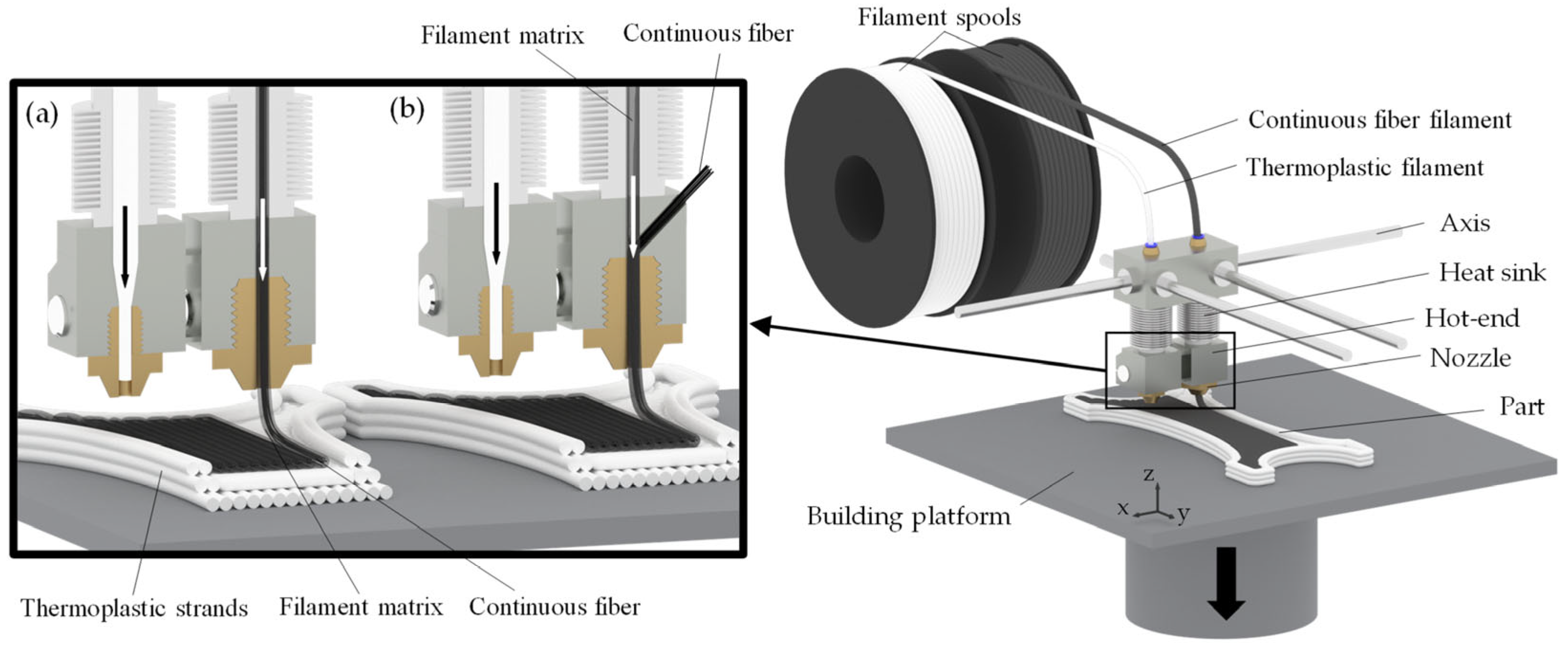
CBAM works by embedding continuous reinforcing fibers within a thermoplastic matrix, building parts layer by layer, as shown in Figure 24. This method is an advanced form of Fused Filament Fabrication (FFF). It uses a special print head with two nozzles: one extrudes a standard engineering thermoplastic (the matrix), while the other feeds a continuous strand of high-strength fiber, such as carbon fiber, fiberglass, or Kevlar, directly into the molten plastic during deposition [102]. The software lets users place these fibers only where extra strength is needed, like around edges, holes, or internal lattice structures. This creates parts that are reinforced inside, similar to rebar in concrete, resulting in objects with excellent strength-to-weight ratios. CBAM is a cost-effective technology that creates lightweight, load-bearing parts with metal-like strength by strategically embedding continuous fibers into 3D printed components [103].
Materials Used in CBAM: The materials in CBAM combine a thermoplastic matrix and continuous reinforcing fibers. The matrix, which forms the main body of the part, is usually a durable, engineering-grade thermoplastic like nylon or a chopped carbon fiber-filled nylon such as Onyx, which offers strength, dimensional stability, and a good surface finish [104]. The strength mainly comes from the continuous fibers embedded in the matrix. Options include carbon fiber for maximum strength and stiffness, fiberglass as a cost-effective strong alternative, Kevlar for toughness and impact resistance, and specialized high-strength and high-temperature fiberglass for parts exposed to high temperatures.

2.6. Directed Energy Deposition (DED)

Directed Energy Deposition is an advanced AM technique that uses focused thermal energy, such as a laser, electron beam, or plasma arc, to melt materials as they are being deposited. Typically used for metal parts, DED enables precise repair, coating, or fabrication by feeding metal powder or wire into the melt pool generated by the energy source. It is ideal for producing complex geometries, repairing high-value components, and adding material to existing structures.

2.6.1. Wire Arc Additive Manufacturing (WAAM)

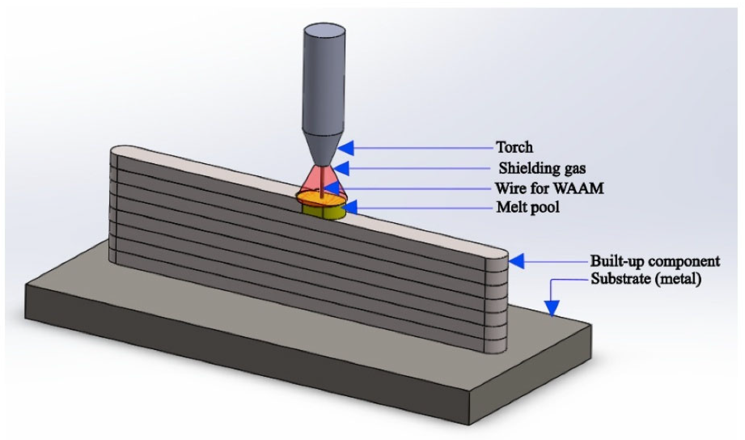
WAAM is a form of DED that uses an electric arc, just like in conventional welding, to build three-dimensional metal objects. The system is typically based on a multi-axis robotic arm or a gantry system equipped with a welding torch and a wire feeding mechanism. The process begins with a digital 3D model that is sliced into layers, which is shown in Figure 25. The robotic arm then precisely guides the welding torch along the path of the first layer while continuously feeding a metal wire into the arc. The intense heat of the arc melts the tip of the wire, and this molten metal is deposited onto a substrate or the previous layer, where it cools and solidifies. This process is repeated layer by layer, essentially drawing the object in 3D with molten metal, until the final, near-net shape part is constructed [105]. It is a highly efficient and cost-effective AM method that uses standard welding equipment and wire feedstock to rapidly produce very-large-scale metal components [106].
Materials Used for WAAM: The materials used for Wire Arc AM are, by nature, any metals that are available in the form of standard welding wire. This provides a vast and well-established library of engineering materials that are already certified for industrial use. Common materials include a wide variety of steels, such as low-carbon steel, stainless steels (e.g., 316L, 308L), and tool steels. Titanium alloys, particularly Ti-6Al-4V, are frequently used for their high strength-to-weight ratio in aerospace applications [107]. Nickel-based superalloys like Inconel 625 and 718 are employed for their excellent high-temperature performance and corrosion resistance. Additionally, aluminum alloys, bronze, and copper alloys are also used, expanding the technology’s reach into marine and electrical applications [108].

2.6.2. Hybrid Additive–Subtractive Manufacturing

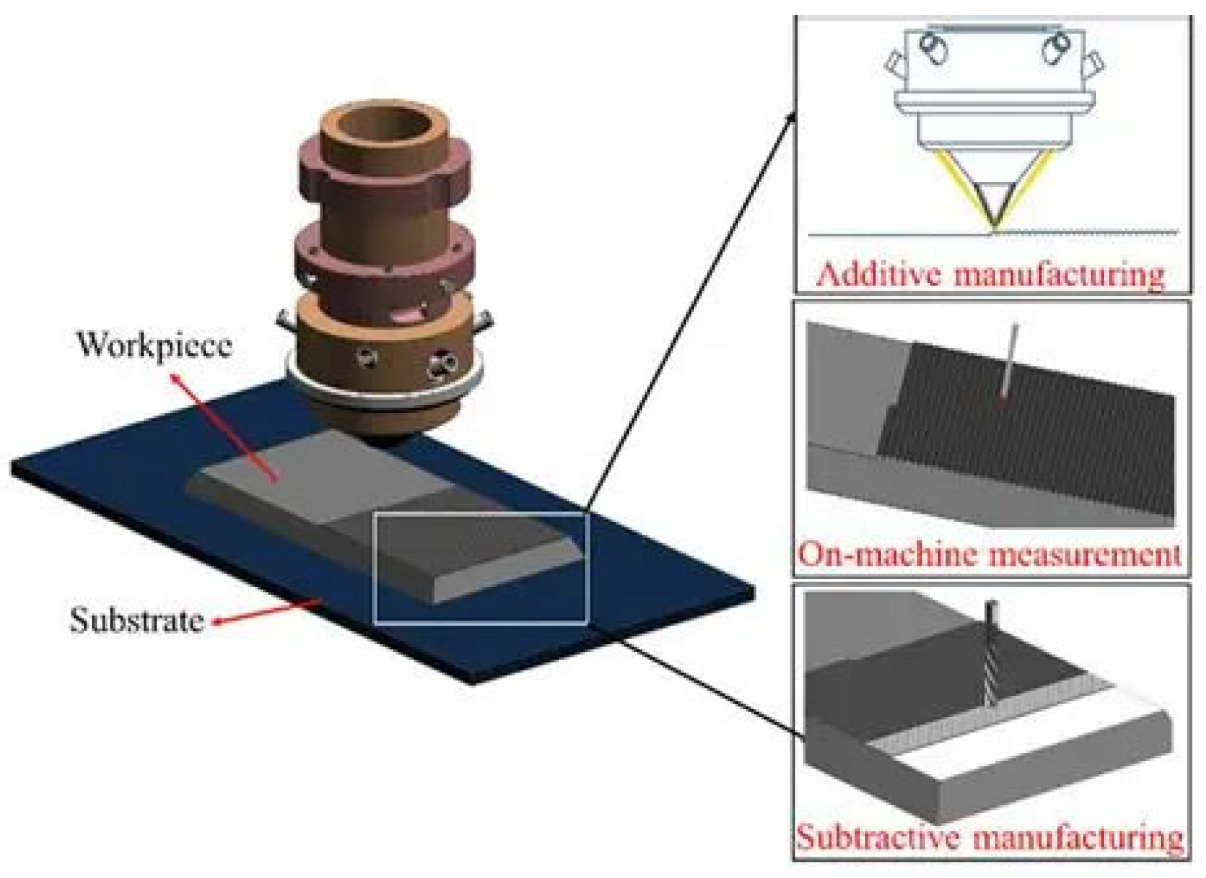
The principle of hybrid additive–subtractive manufacturing is the integration of two opposing processes, additive manufacturing and subtractive manufacturing, into a single, unified machine or workflow, which is shown in Figure 26. The additive part of the process, typically a form of DED like Laser Metal Deposition or WAAM, deposits material layer by layer to build a part’s geometry. The subtractive part, a conventional CNC (Computer Numerical Control) milling or turning tool, is used to machine the part during or after the deposition [109]. The key to the hybrid principle is the ability to alternate between these two functions in situ. A layer or feature can be additively built and then immediately machined to achieve precise dimensions, smooth surfaces, or intricate details before the next feature is added on top of it, making previously inaccessible areas machinable. Hybrid manufacturing combines additive and subtractive processes in a single machine to produce highly complex parts with finished internal features, increasing efficiency and enabling precise component repair [110].
Materials Used for Hybrid Additive–Subtractive Manufacturing: The materials used in hybrid systems depend on the additive process and are usually high-performance metals available as powder or wire. The subtractive tools can machine almost any metal that can be deposited. Common materials include various stainless steels, like 316L and 17-4PH, valued for their corrosion resistance and strength, and tool steels such as H13, used for making durable molds and dies [111]. For demanding applications, nickel-based superalloys like Inconel 718 and 625 are chosen for their excellent strength at high temperatures. Titanium alloys, especially Ti-6Al-4V, are essential for lightweight, strong parts in aerospace and medical fields. This technology also allows combining different materials, such as cladding a corrosion-resistant metal over a cheaper base material [112].

2.6.3. Electron Beam Additive Manufacturing (EBAM)

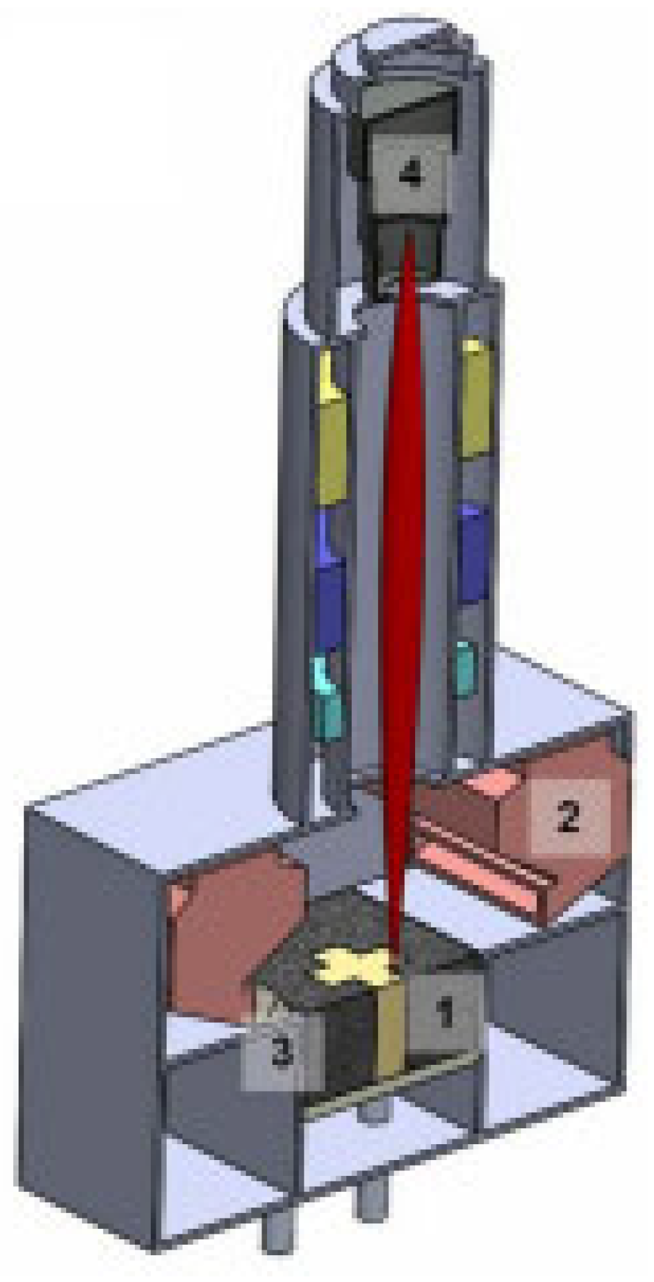
In EBAM, parts are made by fusing powdered metals lay by lay in a chamber that is kept in a high vacuum. A 3D CAD model is first made and then cut into horizontal slices for the next stage. A recoated blade sprinkles a fine amount of metal powder onto a heated build platform which are shown in Figure 27. A quick scan of the whole powder bed is performed by the strong electron beam coming from the tungsten filament before the melting of the powder. At this step, the particles become fused, and their position is stabilized, also decreasing gradients in temperatures. After that, the electron beam is guided by magnetic coils to specifically melt the powder, laying down the 2D design of the layer on the powder bed. Impact with the electrons gives strong energy, or heat, to the powder. This heat ends up melting and blending the powder completely. Next, the platform goes down, extra powder is spread, the process of heating and melting is performed again, and this is repeated until the object is finished [113]. EBAM is a fast, high-temperature vacuum process that produces low-stress, high-purity parts, making it ideal for manufacturing with brittle materials like superalloys [114].
Materials Used in EBAM: EBAM technology is optimized for a specific range of high-performance, conductive metals that benefit from its high-temperature, vacuum environment. Titanium Grade 5 and Commercially Pure are the most popular, since they are used in large amounts by the medical and aviation industries. Cobalt–chrome (CoCr) alloys are widely adapted, mostly for implants that need to be tough and wear-resistant [115]. Besides these, EBAM is important for processing nickel-based superalloys such as Inconel 718 because these alloys are tricky to make without the EBAM method. Copper alloys, such as those named Copper 45 and Copper 26, as well as tantalum belong to these other compatible materials. Acupoints that contain materials with low melting points or high amount of vapor pressure like aluminum are generally avoided in EBAM [116].

2.7. Comparative Analysis of Additive Manufacturing Technologies

Additive manufacturing encompasses a diverse range of technologies, each with distinct principles, material requirements, and application scopes. Understanding the comparative advantages and limitations of these processes is crucial for selecting the most appropriate method for specific engineering and industrial applications. A systematic evaluation of key AM techniques is required to be summarized. Table 1 shows a systematic and comparative analysis of the principal AM technologies. Organized according to the six established AM categories, the matrix demonstrates a fundamental principle of the field: the absence of a universally superior process. Instead, each process is characterized by a distinct performance of compatible materials.

3. Sustainable Green Additive Manufacturing Practices

SGAM focuses on maximizing AM inherent benefits, such as material efficiency and design freedom, while minimizing environmental harm across a product’s life. This involves strategies in design, materials, processing, and end-of-life management. For example, topology optimization and lattice structures reduce part weight and raw material use. Designing parts to be self-supporting or orienting builds optimally minimizes support material and waste [130]. Choosing recycled feedstock and advanced polymers helps break dependence on fossil resources. For thermoset processes, researchers are developing recyclable resins and novel alloys, “green steels” that form their microstructure during printing. Adopting these green design and production practices throughout the AM value chain guided by life-cycle assessments (LCAs) and sustainability standards enables repair, refurbishment, and material recovery, reinforcing the circular economy [131].

3.1. Use of Sustainable and Biodegradable Materials

Additive AM increasingly uses bio-based and biodegradable materials to lower environmental impact. Examples include plant-derived polymers like PLA and PCL. These materials are used especially in biomedical applications because they can safely degrade. AM also integrates natural fibers (e.g., cellulose) and industrial or agricultural waste into feedstock. The goal is to replace conventional plastics with materials that break down at end-of-life [132]. However, bio-based materials often have weaker mechanical properties than traditional plastics. They also require suitable disposal environments to degrade. Balancing eco-friendliness with performance remains a challenge. Advances in materials science are needed to improve biodegradable AM materials without sacrificing sustainability [133]. However, a significant challenge remains in balancing eco-friendliness with thermomechanical performance. As detailed in Table 2, bio-based materials often exhibit lower strength, stiffness, and thermal resistance compared to conventional engineering plastics like ABS or PETG. They may also be more susceptible to moisture absorption, which can affect print quality and part integrity. Ongoing research in materials science is focused on developing advanced bio-composites and polymer blends that enhance these properties without compromising their fundamental biodegradability.

3.2. Recycling and Reuse of Printing Materials

Recycling and reuse are vital for AM’s sustainability. By adopting a circular economy mindset, AM aims to minimize waste and resource use, thus cutting the carbon footprint. Key practices include collecting plastic waste (e.g., failed prints, disposable parts) and converting it into filament or powder. Standard plastics like PLA, ABS, PET, and HDPE can be reprocessed for FDM or material jetting. Similarly, metal AM users can reclaim unused powder: in powder bed fusion, leftover metal powder is sieved, checked, and reused in later builds. These practices significantly improve material efficiency compared to traditional subtractive methods [148]. Some challenges remain: repeated reheating can change powder particle size and chemistry over time. Importantly, AM processes like DED and Wire Arc AM inherently support repair and remanufacturing. They can add material to worn components, effectively refurbishing parts rather than replacing them. This significantly extends part life, saving resources, money, and reducing scrap. In this way, recycling and reuse are fundamental to making AM greener [149].

3.3. Energy-Efficient Printing Processes

AM’s impact on energy use is mixed. Some processes like powder bed fusion require high power during both printing and feedstock production. However, AM often lowers overall energy consumption by reducing waste and enabling lightweight designs [150]. For example, topology-optimized parts use less material and often save energy during the product’s usage phase. In many cases, the energy savings due to the use of lighter parts and fewer transports offset the higher printing energy. In some comparisons, binder jetting has shown considerably lower energy use than conventional CNC machining. Energy efficiency in AM can be further improved by selecting low-energy technologies, optimizing machine settings, and minimizing post-processing. Using renewable energy in AM facilities is also key. Finally, conducting thorough lifecycle assessments helps quantify energy use across all stages and identifies opportunities to make AM more energy efficient. However, energy sources vary dramatically between different AM technologies, as shown in Table 3. Processes like binder jetting have very low energy consumption during the printing stage, as they only require energy to deposit a liquid binder at room temperature. The main energy cost comes later, during the post-processing sintering phase. In contrast, PBF processes like DMLS and EBM are highly energy-intensive due to the need for high-power lasers or electron beams to melt metal powder and maintain a heated build chamber.

3.4. Design for Sustainability

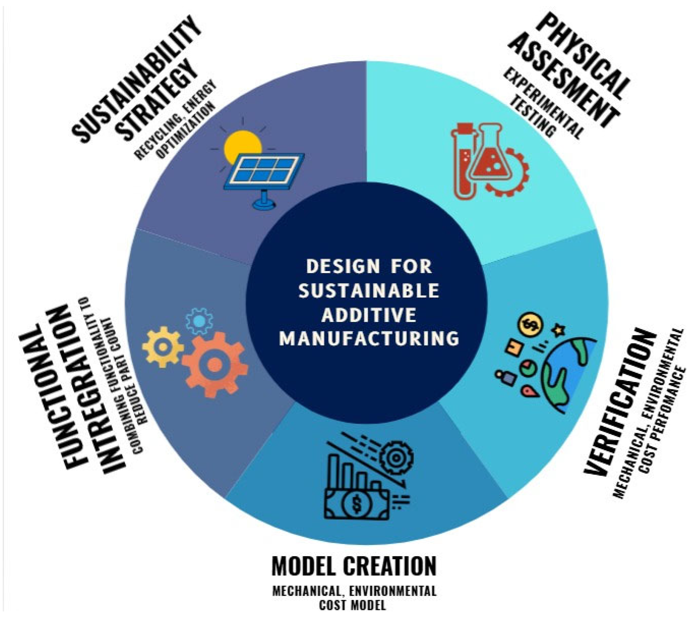
The way a product is designed guides AM users toward environmental benefits. Design for sustainability in AM leverages the technology’s unrestricted shape capabilities. A basis is topology optimization: algorithms remove unnecessary material while preserving function and performance. This dramatically lowers raw material needs and the energy for production, and lighter designs use less energy in operation [131]. Other sustainable design strategies include lattice or honeycomb infill to use less material, part consolidation combining multiple parts into one, and designing for disassembly or recycling. Figure 28 shows some strategies for sustainable additive manufacturing. These approaches ensure AM’s design flexibility leads to real reductions in environmental impact over the entire lifecycle [172].

3.5. Localized and On-Demand Manufacturing

AM enables production models that are distributed and demand-driven. By printing near end-users and only when needed, AM greatly reduces the need to ship parts long distances, cutting transportation energy by orders of magnitude. This also shrinks inventory and warehousing needs, since a “digital stock” of CAD files can be printed on demand [173]. On-demand AM is particularly useful for spare parts and custom items, allowing quick repairs and upgrades that extend product life. Distributed AM can also diversify local industry and create skilled jobs worldwide. For mass-produced standard items, centralized factories remain efficient, but for niche parts and small runs, local AM provides a sustainable alternative. A global network of AM capacity strengthens supply chains and supports greener manufacturing.

3.6. Minimal or No Support Structure Usage

Support structures hold parts in place during printing but can significantly reduce AM’s sustainability. They consume extra material and require additional processing. Manually or chemically removing supports adds time, energy, and potential hazards. To improve sustainability, designers minimize supports. For example, orienting parts optimally and using self-supporting geometries or internal lattices can often eliminate many supports [174]. Some AM processes inherently avoid supports; binder jetting, for instance, uses loose powder to support each layer. Other innovations include easily removable or dissolvable supports and smarter algorithms for generating them. Reducing or eliminating supports not only lowers material use and waste but also shortens build time and post-processing, greatly reducing AM’s environmental footprint. Support structures are often necessary in AM to anchor a part to the build plate and support overhanging features. However, they are fundamentally a source of waste and inefficiency. They consume extra material that is later discarded and require additional time, energy, and often hazardous chemicals for removal [175].

3.7. Lifecycle Assessment (LCA) and Environmental Impact Evaluation

An LCA provides the definitive method for evaluating a product’s true environmental impact, offering a systematic way to compare AM against traditional methods. This analysis reveals a critical trade-off. AM excels for small batches, custom items, and complex geometries, typically using less energy and emitting fewer greenhouse gases [176]. However, for high-volume production, conventional processes like injection molding often become more efficient per part, creating a break-even point determined by part design, material, and process selection. A credible LCA must be holistic, covering the entire cradle-to-grave journey. This begins with the often-overlooked but energy-intensive cradle-to-gate stage, which includes producing the feedstock, such as atomizing metal powders. It then scrutinizes the manufacturing phase, encompassing not just the printer’s direct energy use but also that of ancillary systems and post-processing. The use phase is where AM frequently delivers its greatest environmental dividend; a lightweight AM component in a vehicle, for instance, can significantly reduce fuel consumption over its lifetime, often outweighing its initial production footprint. Finally, the assessment considers the end-of-life stage, evaluating the material’s recyclability [176]. By tracking metrics across these stages, an LCA acts as an essential diagnostic tool. It pinpoints environmental hotspots, guiding engineers to make targeted improvements and enabling AM to fulfill its potential as a truly low-carbon technology.

3.8. Waste Reduction and Material Efficiency

One of additive manufacturing’s most celebrated benefits is its exceptional material efficiency, which stands in stark contrast to traditional subtractive methods. The fundamental additive approach, where material is deposited layer-by-layer only where needed, yields a buy-to-fly ratio the ratio of raw material purchased to the weight of the final part that can approach an impressive 1.1:1. This is a dramatic improvement over CNC machining, where ratios of 10:1 or even 20:1 are common, resulting in vast quantities of scrap [177]. However, despite this inherent advantage, AM is not a zero-waste process, and understanding its unique waste streams is crucial. The primary sources of waste include sacrificial support structures, which consume material only to be discarded; inevitable failed prints and test parts; and process-specific byproducts like spatter in Directed Energy Deposition. Perhaps the most significant challenge lies in PBF systems, where unused metal powder can degrade over time. Repeated thermal cycling and exposure to oxygen during builds can alter the powder’s morphology and chemistry, rendering it unusable for high-performance applications and creating a significant waste stream. To fulfill its promise of minimal-waste manufacturing, a multi-faceted approach is essential. This involves optimizing designs and print orientations to reduce reliance on supports, favoring processes like binder jetting or Multijet Fusion that use loose powder as a natural support system [178]. Furthermore, it requires the implementation of stringent powder lifecycle management protocols, including controlled atmosphere storage, regular sieving to remove agglomerates, and systematic blending with virgin powder to maintain a consistent quality pool. By integrating these advanced process controls with robust, closed-loop recycling for off-cuts and failed parts, the AM industry can move closer to achieving a truly circular and resource-efficient manufacturing ecosystem.

3.9. Eco-Certification and Compliance with Green Standards

Standards and certifications are the bedrock of credibility in sustainable manufacturing, providing a verifiable framework to ensure that the environmental benefits of additive manufacturing (AM) are consistently realized and not just anecdotal. For AM to transition from a promising technology to a recognized pillar of the green economy, it must adhere to rigorous, standardized practices. Currently, while a comprehensive suite of AM-specific standards is still evolving, several established international frameworks are being adopted to guide greener operations. Key among these are ISO 14001 [179], which provides a structure for establishing an environmental management system to track waste and resource use; ISO 50001 [180], which directly addresses the high energy consumption of many AM processes by promoting data-driven energy management; and ISO 14006 [181], which formalizes the integration of eco-design principles like topology optimization and part consolidation [182].
Earning these certifications allows AM manufacturers to formally demonstrate their commitment, meet customer and regulatory requirements, and move beyond unsubstantiated green claims. However, the generalist nature of these standards reveals a significant gap, as a single set of rules cannot effectively govern the diverse and unique challenges across all AM technologies. There is a pressing need to develop a new generation of granular, AM-specific standards. This includes creating protocols for the material lifecycle, such as defining a reusability index for metal powders and certifying the quality of recycled polymer feedstocks. It also involves establishing process-specific guidelines for managing unique hazards, from filtering volatile organic compounds (VOCs) in vat photopolymerization to handling inert gases in powder bed fusion [183,184]. Ultimately, developing these specific, globally recognized standards is the critical next step to eliminate ambiguity, foster trust, and truly advance greener manufacturing across the entire AM industry.

3.10. Education, Training, and Stakeholder Awareness

The successful implementation of SGAM is fundamentally dependent on robust education and training across all stakeholder levels, as technology alone cannot ensure sustainable outcomes. For engineers and designers, this requires a paradigm shift from merely designing for manufacturability to actively practicing design for sustainability. Curricula and professional development must emphasize lifecycle thinking, material selection for low environmental impact, and strategies for minimizing weight, supports, and post-processing energy. Similarly, machine operators and technicians need targeted training beyond basic operation, focusing on energy-saving techniques, proper waste handling, and the protocols for safely recycling materials like metal powders and polymer off-cuts [185].
This effort must be won by industry leaders, educators, and policymakers who can foster a culture of sustainability. Through collaborative workshops, updated academic programs, and industry-recognized certifications, they can raise awareness about the holistic benefits of SGAM, which include enhanced supply chain resilience and long-term economic advantages, not just environmental compliance [186]. Ultimately, stakeholder education ensures that designers consider eco-factors from the very start and that operators follow best practices on the factory floor. Creating this well-informed ecosystem of practitioners and decision-makers is the key catalyst for accelerating the widespread adoption of SGAM, transforming it from a promising concept into an industrial reality.

4. Sustainable Green Additive Manufacturing Challenges

AM has the potential to drive sustainability in production, but several challenges must be addressed. Overcoming issues throughout the AM lifecycle is crucial to creating a truly green manufacturing ecosystem. Challenges range from accurately assessing environmental footprints of processes and materials to ensuring that green materials can meet performance requirements. Practical hurdles include scaling up production, matching the mechanical properties of conventional materials, and making sustainable options economically competitive. Solving these problems is essential if AM is to transition from a promising idea into a mainstream driver of eco-friendly manufacturing.

4.1. Environmental Aspects

AM’s environmental impacts shown in Figure 29 are complex. Many AM processes consume large amounts of energy. For example, powder bed fusion techniques like SML, EBM etc. use high-power beams to melt metal powders, requiring significant energy. Moreover, preparing specialized feedstocks, like atomizing metal powders or producing polymer powders, is also energy intensive. Other environmental issues include waste generation, unused powder that cannot be reused, and emissions from printing polymers like VOCs and ultrafine particles, which can harm air quality and require advanced filtration. Materials like thermoset plastics or multi-material composites can complicate recycling at end-of-life [187]. Therefore, each AM process and material combination needs a thorough LCA to identify its environmental hotspots. Reducing waste alone is not enough if other stages like energy or emissions dominate the footprint.

4.2. Material Compatibility

Advancing SGAM depends on using eco-friendly materials, but ensuring they work well in existing AM systems is challenging. Most machines and processes were developed for uniform petroleum-based polymers or specific metal alloys. Introducing new bio-polymers, PLA, PHA, cellulose-based materials, recycled plastics rPET, rABS, and natural fiber composites can cause problems [146]. Each new material has its own rheology and thermal behavior; for example, biopolymers may degrade if heated too much or solidify if not hot enough, while recycled plastics may vary in composition between batches. Adding fibers can clog nozzles or lead to poor mixing. As a result, printed layers may not bond well, causing warping or weak parts. Overcoming this requires material science solutions: additives like compatibilizers, plasticizers, and process improvements, drying, and compounding to tailor sustainable materials for AM without undermining their eco-advantages [188]. Each new material introduces unique variables that disrupt the established material–process–property relationship. The core issues stem from fundamental differences in rheology, thermal properties, and compositional consistency. Table 4 summarizes these key challenges and outlines corresponding solutions.

4.3. Scalability of Manufacturing Process

Demonstrating green AM at lab scale is one thing; scaling up to large-scale production is another challenge. Scaling involves more than just adding machines: issues of throughput, consistency, and supply chains arise. Many AM processes are inherently slower than traditional mass-production methods like injection molding, and they slow further when using eco-friendly materials. Ensuring a stable supply of bio-based or recycled feedstock is also critical. For example, variations in recycled plastic batches require real-time process adjustments that add cost and complexity [191]. Additionally, extensive post-processing support removal, surface finishing, and curing remain mostly manual and can bottleneck production. Without solutions to these throughput and supply-chain issues, sustainable AM will struggle to reach mass production. The path to scalability involves far more than simply multiplying the number of machines; it demands a systemic overhaul of throughput, process consistency, and supply-chain logistics [192]. Many AM processes are inherently slower than traditional mass-production methods like injection molding, and this speed disadvantage is often exacerbated when working with sensitive, eco-friendly materials. Table 5 offers a comparison highlighting the scalability gap between traditional manufacturing and the current state of green AM.

4.4. Mechanical Property Optimization

Sustainable materials must meet performance requirements to be adopted. Currently, many eco-friendly polymers and bio composites are weaker and less heat-resistant than traditional materials. The layer-by-layer nature of AM often causes anisotropy different strength in different directions and defects like porosity or weak interlayer bonds. Addressing these issues requires material innovations compatibilized bio-composites, better recycled blends, and process optimization tuning extrusion temperature, print speed, and geometry [193]. Advanced design methods like topology optimization can place material where it is needed to compensate for weaker properties. Post-processing such as annealing or chemical treatment can further enhance strength. Ultimately, it is crucial to strike a balance so that sustainability gains are not undermined by poor performance. Currently, a significant performance gap exists, as many eco-friendly polymers (e.g., PLA, PHA) and bio-composites exhibit lower strength, stiffness, and heat resistance compared to their petroleum-based counterparts (e.g., ABS, PC, nylon) [194]. The optimization strategies must be applied synergistically, as shown in Table 6, to ensure that the gains in sustainability are not undermined by poor performance in the final application.

4.5. Cost of Sustainable Materials

Higher material costs often limit SGAM adoption. Sustainable feedstocks can be more expensive because of the additional processing, smaller scale of production, and ongoing R&D needed to prepare them. In contrast, traditional polymers and alloys benefit from mature, high-volume supply chains. To overcome this, technological improvements and economies of scale are needed to lower costs. Market incentives and policies like subsidies or carbon credits can encourage adoption of greener materials. When factoring in the full lifecycle, savings from reduced waste and potential carbon benefits can also help justify the initial premium [202]. Table 7 provides a comparative analysis of the cost structures, highlighting the visible and hidden costs associated with traditional versus sustainable feedstocks.

5. Future Directions

Overcoming today’s challenges will enable a truly sustainable AM ecosystem. The future of SGAM lies in continuous innovation. Researchers are actively developing new eco-friendly materials and improving processes. In the coming years, AM technology will increasingly integrate sustainability principles from material development to energy use and lifecycle management driven by new technologies and industry collaboration.

5.1. The Development of New Green Materials and Technologies

The future of SGAM depends on creating novel eco-friendly feedstocks and processes. Research is focusing on new biopolymers such as PHAs, lignin-based plastics, and algae-derived resins and bio composites made with local natural fillers like nanocellulose and agricultural residues. Intriguingly, living materials self-growing microbial polymers could emerge as sustainable options [203]. On the process side, new AM hardware will evolve, for example, modified extrusion and powder systems for these novel materials, as well as real-time monitoring to ensure build quality. Low-energy methods like LED-curing of bio-resins or microwave-assisted sintering are being explored. Integrating different sustainable materials into multi-material AM systems will allow innovative, eco-optimized products. Overall, close collaboration between materials development and process innovation is vital to advance green AM. The current generation of sustainable materials like PLA and rPET is merely the beginning. The future lies in a much broader and more sophisticated material palette, coupled with advanced manufacturing technologies designed explicitly for sustainability [202]. Table 8 shows some emerging materials’ advantages and challenges to their use in AM.

5.2. Challenges in Material Optimization, Recycling, and Energy Efficiency

Sustainably achieving SGAM requires simultaneously addressing material performance, recycling, and energy use. Future work must match the strength and durability of green materials to conventional ones, for example through advanced blends, nano-fillers, and computational design [212]. We must also understand how materials age in AM. Recycling challenges require truly circular designs: beyond using recycled inputs, AM parts should be designed for easy recycling at end-of-life. This includes chemical recycling for complex polymers and efficient sorting or preprocessing of AM waste. On the energy front, comprehensive lifecycle analyses can highlight where to cut energy use—whether by improving thermal control in printers, speeding up builds, or integrating renewable power. Software tools that minimize print energy and efficient post-processing heat treatment are also key. These improvements in synergy are essential to scale up SGAM [213]. Future work must therefore focus on the optimization of these three critical parameters, which is shown in Table 9.

5.3. Strategies for Further Integrating Eco-Friendly Materials into AM Processes

To accelerate SGAM, industry-wide efforts are needed. Standardized specifications and certifications for sustainable AM materials and processes will encourage their use. Providing manufacturers with open-access data and design tools for green materials can speed adoption. Public policy also plays a role; for example, governments can offer incentives or procurement preferences for low-carbon products. Regulatory frameworks that factor in CO2 emissions or resource recovery rewards sustainable manufacturing. Finally, joint public–private initiatives along with specialized education and training programs can help industry players implement SGAM practices and technologies [214].
Alongside these technical foundations, powerful economic and regulatory drivers are needed to create a market that favors sustainability. Governments can play a pivotal role by implementing policies such as direct financial incentives for using recycled content or procurement preferences that award public contracts to firms using low-carbon manufacturing. Furthermore, regulatory frameworks that internalize environmental costs such as carbon pricing or Extended Producer Responsibility (EPR) schemes are essential [215]. These measures shift the economic calculus, making sustainable choices not only ethically responsible but also financially advantageous, effectively rewarding resource recovery and penalizing waste.
Emerging technologies such as artificial intelligence, digital twins, and predictive analytics will play a foundational role in driving the next phase of sustainable additive manufacturing. By enabling intelligent material selection, real-time process control, and lifecycle forecasting, these tools will not only enhance performance and efficiency but also embed sustainability into every stage of the AM workflow—from design to end-of-life.

6. Summary

SGAM is gaining momentum as industries look for cleaner, more efficient ways to produce. This summary brings together the main ideas explored throughout this comprehensive review work:
  • A variety of additive manufacturing processes—including Fused Deposition Modeling, Selective Laser Sintering, Direct Ink Writing, binder jetting, and hybrid and low-energy printing methods—are being adapted or redesigned to accommodate sustainable materials and improve energy efficiency across the production lifecycle.
  • Emerging green materials such as PLA, PHA, lignin-based resins, and algae-based bioplastics are increasingly used to reduce fossil fuel dependency and promote biodegradable end-of-life pathways.
  • Recycled feedstocks, including rPET, rABS, rHDPE, and reclaimed metal powders, support circular economy principles and help convert post-consumer and industrial waste into valuable inputs for AM.
  • Innovative material strategies, like bio-based resins designed for reusability and “green steel” produced through additive-controlled heat cycles, demonstrate how material science contributes to minimizing environmental impact.
  • Challenges remain, particularly in ensuring material compatibility, process scalability, and consistent mechanical performance due to the variable properties of green materials.
  • Predictive modeling and AI-driven tools are vital in addressing these challenges by simulating material behavior, optimizing printing parameters, and forecasting part performance across various metrics, including strength, thermal stability, and degradation.
  • LCA and sustainability analysis tools should be integrated into AM workflows to evaluate and minimize the environmental footprint of products from material selection to end-of-life.
  • The integration of material science with machine learning and sustainable design principles will be central to enabling scalable, eco-efficient, and circular additive manufacturing systems.
Collectively, these advancements reflect a growing convergence of sustainable materials, circular design principles, and intelligent modeling tools—paving the way for additive manufacturing to become a truly viable solution for environmentally responsible production.

Author Contributions

Conceptualization, M.M.R. and M.N.U.; methodology, S.D.D. and M.M.R.; formal analysis, S.D.D., M.M.R. and M.J.A.; investigation, M.M.R., M.J.A. and and M.N.U.; resources, S.D.D. and M.M.R.; writing—original draft preparation, S.D.D. and M.M.R.; writing—review and editing, M.J.A. and and M.N.U.; visualization, S.D.D. and M.M.R.; supervision, M.M.R. and M.N.U.; project administration, M.M.R. and M.J.A.; All authors have read and agreed to the published version of the manuscript.

Funding

This research received no external funding.

Conflicts of Interest

The authors declare no conflicts of interest.

References

  1. Su, J.; Ng, W.L.; An, J.; Yeong, W.Y.; Chua, C.K.; Sing, S.L. Achieving Sustainability by Additive Manufacturing: A State-of-the-Art Review and Perspectives. Virtual Phys. Prototyp. 2024, 19, e2438899. [Google Scholar] [CrossRef]
  2. Ford, S.; Despeisse, M. Additive Manufacturing and Sustainability: An Exploratory Study of the Advantages and Challenges. J. Clean. Prod. 2016, 137, 1573–1587. [Google Scholar] [CrossRef]
  3. Kawalkar, R.; Dubey, H.K.; Lokhande, S.P. A Review for Advancements in Standardization for Additive Manufacturing. Mater. Today Proc. 2022, 50, 1983–1990. [Google Scholar] [CrossRef]
  4. Attaran, M. The Rise of 3-D Printing: The Advantages of Additive Manufacturing over Traditional Manufacturing. Bus. Horiz. 2017, 60, 677–688. [Google Scholar] [CrossRef]
  5. Faheem, A.; Hasan, M.A.; Badhotiya, G.K.; Ali, S.M. A Systematic Literature Review to Examine the Role of Additive Manufacturing in Achieving Sustainable Development Goals. Sustain. Oper. Comput. 2024, 5, 216–226. [Google Scholar] [CrossRef]
  6. Mehrpouya, M.; Vahabi, H.; Barletta, M.; Laheurte, P.; Langlois, V. Additive Manufacturing of Polyhydroxyalkanoates (PHAs) Biopolymers: Materials, Printing Techniques, and Applications. Mater. Sci. Eng. C 2021, 127, 112216. [Google Scholar] [CrossRef]
  7. Krapež Tomec, D.; Kariž, M. Use of Wood in Additive Manufacturing: Review and Future Prospects. Polymers 2022, 14, 1174. [Google Scholar] [CrossRef]
  8. Elsacker, E.; Peeters, E.; De Laet, L. Large-Scale Robotic Extrusion-Based Additive Manufacturing with Living Mycelium Materials. Sustain. Futur. 2022, 4, 100085. [Google Scholar] [CrossRef]
  9. Cheah, W.Y.; Er, A.C.; Aiyub, K.; Mohd Yasin, N.H.; Ngan, S.L.; Chew, K.W.; Khoo, K.S.; Ling, T.C.; Juan, J.C.; Ma, Z.; et al. Current Status and Perspectives of Algae-Based Bioplastics: A Reviewed Potential for Sustainability. Algal Res. 2023, 71, 103078. [Google Scholar] [CrossRef]
  10. Malabadi, R.B.; Chalannavar, R.K.; Divakar, B.S.; Kv, K.; Kamble, A.A.; Karamchand, K.S.; Kolkar, K.P.; Tl, N.; Coronado, K.V.C.; Munhoz, A.N.; et al. Industrial Cannabis Sativa (Fiber or Hemp): 3D Printing-Hempcrete-a Sustainable Building Material. World J. Adv. Eng. Technol. Sci. 2025, 14, 253–282. [Google Scholar] [CrossRef]
  11. Fredriksson, C. Sustainability of Metal Powder Additive Manufacturing. Procedia Manuf. 2019, 33, 139–144. [Google Scholar] [CrossRef]
  12. Giani, N.; Mazzocchetti, L.; Benelli, T.; Picchioni, F.; Giorgini, L. Towards Sustainability in 3D Printing of Thermoplastic Composites: Evaluation of Recycled Carbon Fibers as Reinforcing Agent for FDM Filament Production and 3D Printing. Compos. Part Appl. Sci. Manuf. 2022, 159, 107002. [Google Scholar] [CrossRef]
  13. Shifa, S.S.; Hasan Kanok, M.M.; Haque, M.S.; Sultan, T.; Pritha, K.F.; Mubasshira; Al Yeamin, M.; Dipta, S.D. Influence of Heat Treatment and Water Absorption on Mechanical Properties of Cotton-Glass Fiber Reinforced Epoxy Hybrid Composites: An Eco-Friendly Approach for Industrial Materials. Hybrid Adv. 2024, 5, 100181. [Google Scholar] [CrossRef]
  14. Maware, C.; Muvunzi, R.; Machingura, T.; Daniyan, I. Examining the Progress in Additive Manufacturing in Supporting Lean, Green and Sustainable Manufacturing: A Systematic Review. Appl. Sci. 2024, 14, 6041. [Google Scholar] [CrossRef]
  15. Gopal, M.; Lemu, H.G.; Gutema, E.M. Sustainable Additive Manufacturing and Environmental Implications: Literature Review. Sustainability 2022, 15, 504. [Google Scholar] [CrossRef]
  16. Altıparmak, S.C.; Yardley, V.A.; Shi, Z.; Lin, J. Extrusion-Based Additive Manufacturing Technologies: State of the Art and Future Perspectives. J. Manuf. Process. 2022, 83, 607–636. [Google Scholar] [CrossRef]
  17. Acierno, D.; Patti, A. Fused Deposition Modelling (FDM) of Thermoplastic-Based Filaments: Process and Rheological Properties—An Overview. Materials 2023, 16, 7664. [Google Scholar] [CrossRef] [PubMed]
  18. Zhou, L.; Miller, J.; Vezza, J.; Mayster, M.; Raffay, M.; Justice, Q.; Tamimi, Z.A.; Hansotte, G.; Sunkara, L.D.; Bernat, J. Additive Manufacturing: A Comprehensive Review. Sensors 2024, 24, 2668. [Google Scholar] [CrossRef] [PubMed]
  19. Bhatia, A.; Sehgal, A.K. Additive Manufacturing Materials, Methods and Applications: A Review. Mater. Today Proc. 2023, 81, 1060–1067. [Google Scholar] [CrossRef]
  20. Madhu, N.R.; Erfani, H.; Jadoun, S.; Amir, M.; Thiagarajan, Y.; Chauhan, N.P.S. Fused Deposition Modelling Approach Using 3D Printing and Recycled Industrial Materials for a Sustainable Environment: A Review. Int. J. Adv. Manuf. Technol. 2022, 122, 2125–2138. [Google Scholar] [CrossRef]
  21. Solís Pinargote, N.W.; Smirnov, A.; Peretyagin, N.; Seleznev, A.; Peretyagin, P. Direct Ink Writing Technology (3D Printing) of Graphene-Based Ceramic Nanocomposites: A Review. Nanomaterials 2020, 10, 1300. [Google Scholar] [CrossRef]
  22. Cadiou, T.; Demoly, F.; Gomes, S. A Hybrid Additive Manufacturing Platform Based on Fused Filament Fabrication and Direct Ink Writing Techniques for Multi-Material 3D Printing. Int. J. Adv. Manuf. Technol. 2021, 114, 3551–3562. [Google Scholar] [CrossRef]
  23. Rau, D.A.; Williams, C.B.; Bortner, M.J. Rheology and Printability: A Survey of Critical Relationships for Direct Ink Write Materials Design. Prog. Mater. Sci. 2023, 140, 101188. [Google Scholar] [CrossRef]
  24. Hao, L.; Tang, D.; Sun, T.; Xiong, W.; Feng, Z.; Evans, K.E.; Li, Y. Direct Ink Writing of Mineral Materials: A Review. Int. J. Precis. Eng. Manuf.-Green Technol. 2021, 8, 665–685. [Google Scholar] [CrossRef]
  25. Alami, A.H.; Olabi, A.G.; Ayoub, M.; Aljaghoub, H.; Alasad, S.; Abdelkareem, M.A. 3D Concrete Printing: Recent Progress, Applications, Challenges, and Role in Achieving Sustainable Development Goals. Buildings 2023, 13, 924. [Google Scholar] [CrossRef]
  26. Colyn, M.; van Zijl, G.; Babafemi, A.J. Fresh and Strength Properties of 3D Printable Concrete Mixtures Utilising a High Volume of Sustainable Alternative Binders. Constr. Build. Mater. 2024, 419, 135474. [Google Scholar] [CrossRef]
  27. Ryan, K.R.; Down, M.P.; Banks, C.E. Future of Additive Manufacturing: Overview of 4D and 3D Printed Smart and Advanced Materials and Their Applications. Chem. Eng. J. 2021, 403, 126162. [Google Scholar] [CrossRef]
  28. Waheed, S.; Cabot, J.M.; Macdonald, N.P.; Lewis, T.; Guijt, R.M.; Paull, B.; Breadmore, M.C. 3D Printed Microfluidic Devices: Enablers and Barriers. Lab. Chip 2016, 16, 1993–2013. [Google Scholar] [CrossRef] [PubMed]
  29. Huang, J.; Qin, Q.; Wang, J. A Review of Stereolithography: Processes and Systems. Processes 2020, 8, 1138. [Google Scholar] [CrossRef]
  30. Meana, V.; Zapico, P.; Cuesta, E.; Giganto, S.; Meana, L.; Martínez-Pellitero, S. Additive Manufacturing of Ceramic Reference Spheres by Stereolithography (SLA). Appl. Sci. 2024, 14, 7530. [Google Scholar] [CrossRef]
  31. Wang, H.; Zhang, W.; Ladika, D.; Yu, H.; Gailevičius, D.; Wang, H.; Pan, C.; Nair, P.N.S.; Ke, Y.; Mori, T.; et al. Two-Photon Polymerization Lithography for Optics and Photonics: Fundamentals, Materials, Technologies, and Applications. Adv. Funct. Mater. 2023, 33, 2214211. [Google Scholar] [CrossRef]
  32. Sampson, K.L.; Deore, B.; Go, A.; Nayak, M.A.; Orth, A.; Gallerneault, M.; Malenfant, P.R.L.; Paquet, C. Multimaterial Vat Polymerization Additive Manufacturing. ACS Appl. Polym. Mater. 2021, 3, 4304–4324. [Google Scholar] [CrossRef]
  33. Almuallim, B.; Harun, W.S.W.; Al Rikabi, I.J.; Mohammed, H.A. Thermally Conductive Polymer Nanocomposites for Filament-Based Additive Manufacturing. J. Mater. Sci. 2022, 57, 3993–4019. [Google Scholar] [CrossRef]
  34. Huang, J.; Cai, J.; Huangfu, C.; Li, S.; Chen, G.; Yun, H.; Xiao, J. A Scalable Digital Light Processing 3D Printing Method. Micromachines 2024, 15, 1298. [Google Scholar] [CrossRef] [PubMed]
  35. Chaudhary, R.; Akbari, R.; Antonini, C. Rational Design and Characterization of Materials for Optimized Additive Manufacturing by Digital Light Processing. Polymers 2023, 15, 287. [Google Scholar] [CrossRef]
  36. Zhou, C.; Xu, H.; Chen, Y. Spatiotemporal Projection-Based Additive Manufacturing: A Data-Driven Image Planning Method for Subpixel Shifting in a Split Second. Adv. Intell. Syst. 2021, 3, 2100079. [Google Scholar] [CrossRef]
  37. Prashar, G. A Comprehensive Review on Sustainable Cold Spray Additive Manufacturing: State of the Art, Challenges and Future Challenges. J. Clean. Prod. 2021, 310, 127606. [Google Scholar] [CrossRef]
  38. Kaijage, D.J.; Lee, B.J. Multiphysics Simulation of Continuous Liquid Interface Production (CLIP) 3D Printing Technology. Int. J. Precis. Eng. Manuf.-Green Technol. 2025, 12, 541–552. [Google Scholar] [CrossRef]
  39. Czajkowska, M.; Walejewska, E.; Zadrożny, Ł.; Wieczorek, M.; Święszkowski, W.; Wagner, L.; Mijiritsky, E.; Markowski, J. Comparison of Dental Stone Models and Their 3D Printed Acrylic Replicas for the Accuracy and Mechanical Properties. Materials 2020, 13, 4066. [Google Scholar] [CrossRef]
  40. Rosu, M.M.; Radu Frent, C.; Iliescu, M. Technical and Economic Analysis of Manufacturing Process for High Precision Customized Part. Int. J. Mod. Manuf. Technol. 2022, 14, 215–219. [Google Scholar] [CrossRef]
  41. Abdulhameed, O.; Al-Ahmari, A.; Ameen, W.; Mian, S.H. Additive Manufacturing: Challenges, Trends, and Applications. Adv. Mech. Eng. 2019, 11, 1687814018822880. [Google Scholar] [CrossRef]
  42. Lipkowitz, G.; Samuelsen, T.; Hsiao, K.; Lee, B.; Dulay, M.T.; Coates, I.; Lin, H.; Pan, W.; Toth, G.; Tate, L.; et al. Injection Continuous Liquid Interface Production of 3D Objects. Sci. Adv. 2022, 8, eabq3917. [Google Scholar] [CrossRef] [PubMed]
  43. Huang, B.; Hu, R.; Xue, Z.; Zhao, J.; Li, Q.; Xia, T.; Zhang, W.; Lu, C. Continuous Liquid Interface Production of Alginate/Polyacrylamide Hydrogels with Supramolecular Shape Memory Properties. Carbohydr. Polym. 2020, 231, 115736. [Google Scholar] [CrossRef] [PubMed]
  44. Davoudinejad, A. Vat Photopolymerization Methods in Additive Manufacturing. In Additive Manufacturing; Elsevier: Amsterdam, The Netherlands, 2021; pp. 159–181. ISBN 978-0-12-818411-0. [Google Scholar]
  45. Gu, P.; Zhang, X.; Zeng, Y.; Ferguson, B. Quality Analysis and Optimization of Solid Ground Curing Process. J. Manuf. Syst. 2001, 20, 250–263. [Google Scholar] [CrossRef]
  46. Qu, C.; Qin, Y.; Wang, T. From Cement to Geopolymers: Performances and Sustainability Advantages of Ambient Curing. J. Build. Eng. 2024, 91, 109555. [Google Scholar] [CrossRef]
  47. Qi, Z.; Li, J.; Huang, G.; Zhong, F.; Xue, Q. Developing All-Solid-Waste-Based Curing Agents with Net-Zero Emissions for Engineering Sediment Waste Stabilization. Resour. Conserv. Recycl. 2025, 220, 108354. [Google Scholar] [CrossRef]
  48. Zol, S.M.; Alauddin, M.S.; Said, Z.; Mohd Ghazali, M.I.; Hao-Ern, L.; Mohd Farid, D.A.; Zahari, N.A.H.; Al-Khadim, A.H.A.; Abdul Aziz, A.H. Description of Poly(Aryl-Ether-Ketone) Materials (PAEKs), Polyetheretherketone (PEEK) and Polyetherketoneketone (PEKK) for Application as a Dental Material: A Materials Science Review. Polymers 2023, 15, 2170. [Google Scholar] [CrossRef]
  49. Pyteraf, J.; Pacławski, A.; Jamróz, W.; Mendyk, A.; Paluch, M.; Jachowicz, R. Application and Multi-Stage Optimization of Daylight Polymer 3D Printing of Personalized Medicine Products. Pharmaceutics 2022, 14, 843. [Google Scholar] [CrossRef]
  50. Smith, G.B. Materials and Systems for Efficient Lighting and Delivery of Daylight. Sol. Energy Mater. Sol. Cells 2004, 84, 395–409. [Google Scholar] [CrossRef]
  51. Saleh Alghamdi, S.; John, S.; Roy Choudhury, N.; Dutta, N.K. Additive Manufacturing of Polymer Materials: Progress, Promise and Challenges. Polymers 2021, 13, 753. [Google Scholar] [CrossRef] [PubMed]
  52. Charoo, N.A.; Barakh Ali, S.F.; Mohamed, E.M.; Kuttolamadom, M.A.; Ozkan, T.; Khan, M.A.; Rahman, Z. Selective Laser Sintering 3D Printing—An Overview of the Technology and Pharmaceutical Applications. Drug Dev. Ind. Pharm. 2020, 46, 869–877. [Google Scholar] [CrossRef] [PubMed]
  53. Lekurwale, S.; Karanwad, T.; Banerjee, S. Selective Laser Sintering (SLS) of 3D Printlets Using a 3D Printer Comprised of IR/Red-Diode Laser. Ann. 3D Print. Med. 2022, 6, 100054. [Google Scholar] [CrossRef]
  54. Nandhakumar, R.; Venkatesan, K. A Process Parameters Review on Selective Laser Melting-Based Additive Manufacturing of Single and Multi-Material: Microstructure, Physical Properties, Tribological, and Surface Roughness. Mater. Today Commun. 2023, 35, 105538. [Google Scholar] [CrossRef]
  55. Giudice, F.; Barbagallo, R.; Fargione, G. A Design for Additive Manufacturing Approach Based on Process Energy Efficiency: Electron Beam Melted Components. J. Clean. Prod. 2021, 290, 125185. [Google Scholar] [CrossRef]
  56. Islam, M.A.; Mobarak, M.H.; Rimon, M.I.H.; Al Mahmud, M.Z.; Ghosh, J.; Ahmed, M.M.S.; Hossain, N. Additive Manufacturing in Polymer Research: Advances, Synthesis, and Applications. Polym. Test. 2024, 132, 108364. [Google Scholar] [CrossRef]
  57. Sefene, E.M. State-of-the-Art of Selective Laser Melting Process: A Comprehensive Review. J. Manuf. Syst. 2022, 63, 250–274. [Google Scholar] [CrossRef]
  58. Wang, Z.; Ummethala, R.; Singh, N.; Tang, S.; Suryanarayana, C.; Eckert, J.; Prashanth, K.G. Selective Laser Melting of Aluminum and Its Alloys. Materials 2020, 13, 4564. [Google Scholar] [CrossRef] [PubMed]
  59. Ansari, M.J.; Nguyen, D.-S.; Park, H.S. Investigation of SLM Process in Terms of Temperature Distribution and Melting Pool Size: Modeling and Experimental Approaches. Materials 2019, 12, 1272. [Google Scholar] [CrossRef]
  60. Farhang, B.; Tanrikulu, A.A.; Ganesh-Ram, A.; Durlov, S.H.; Shayesteh Moghaddam, N. Innovative Fabrication Design for In Situ Martensite Decomposition and Enhanced Mechanical Properties in Laser Powder Bed Fused Ti6Al4V Alloy. J. Manuf. Mater. Process. 2023, 7, 226. [Google Scholar] [CrossRef]
  61. Tanrikulu, A.A.; Farhang, B.; Ganesh-Ram, A.; Hekmatjou, H.; Durlov, S.H.; Amerinatanzi, A. In Situ Microstructure Modification Using a Layerwise Surface-Preheating Laser Scan of Ti-6Al-4V during Laser Powder Bed Fusion. Materials 2024, 17, 1929. [Google Scholar] [CrossRef]
  62. Tanrikulu, A.A.; Ganesh-Ram, A.; Hekmatjou, H.; Durlov, S.H.; Salehin, M.N.; Amerinatanzi, A. Single-Composition Functionally Graded Ti-6Al-4V for Mimicking Composite Material Fiber Reinforcement through Post-Heating Laser Scanning. Int. J. Adv. Manuf. Technol. 2025, 136, 1297–1315. [Google Scholar] [CrossRef]
  63. Sivarupan, T.; Upadhyay, M.; Ali, Y.; El Mansori, M.; Dargusch, M.S. Reduced Consumption of Materials and Hazardous Chemicals for Energy Efficient Production of Metal Parts through 3D Printing of Sand Molds. J. Clean. Prod. 2019, 224, 411–420. [Google Scholar] [CrossRef]
  64. Ralls, A.M.; Menezes, P.L. Understanding the Tribo-Corrosion Mechanisms of Friction Stir Processed Steel Deposited by High-Pressure Deposition Additive Manufacturing Process. Int. J. Adv. Manuf. Technol. 2023, 128, 823–843. [Google Scholar] [CrossRef]
  65. Lomo, F.N.; Patel, M.J.; Vargas-Uscategui, A.; King, P.C.; Cole, I.S. A Design and Optimisation Framework for Cold Spray Additive Manufacturing of Lightweight Aerospace Structural Components. Addit. Manuf. 2023, 78, 103891. [Google Scholar] [CrossRef]
  66. Kafle, A.; Silwal, R.; Koirala, B.; Zhu, W. Advancements in Cold Spray Additive Manufacturing: Process, Materials, Optimization, Applications, and Challenges. Materials 2024, 17, 5431. [Google Scholar] [CrossRef] [PubMed]
  67. Zou, Y. Cold Spray Additive Manufacturing: Microstructure Evolution and Bonding Features. Acc. Mater. Res. 2021, 2, 1071–1081. [Google Scholar] [CrossRef]
  68. Blunk, H.; Seibel, A. Design Guidelines for Metal Binder Jetting. Prog. Addit. Manuf. 2024, 9, 725–732. [Google Scholar] [CrossRef]
  69. Li, M.; Du, W.; Elwany, A.; Pei, Z.; Ma, C. Metal Binder Jetting Additive Manufacturing: A Literature Review. J. Manuf. Sci. Eng. 2020, 142, 090801. [Google Scholar] [CrossRef]
  70. Gibson, I.; Rosen, D.; Stucker, B.; Khorasani, M. Binder Jetting. In Additive Manufacturing Technologies; Springer International Publishing: Cham, Switzerland, 2021; pp. 237–252. ISBN 978-3-030-56126-0. [Google Scholar]
  71. Sarila, V.; Koneru, H.P.; Pyatla, S.; Cheepu, M.; Kantumunchu, V.C.; Ramachandran, D. An Overview on 3D Printing of Ceramics Using Binder Jetting Process. In Proceedings of the International Conference on Processing and Performance of Materials (ICPPM 2023), Chennai, India, 2–3 March 2023; MDPI: Basel, Switzerland, 2024; p. 44. [Google Scholar]
  72. Mostafaei, A.; Elliott, A.M.; Barnes, J.E.; Li, F.; Tan, W.; Cramer, C.L.; Nandwana, P.; Chmielus, M. Binder Jet 3D Printing—Process Parameters, Materials, Properties, Modeling, and Challenges. Prog. Mater. Sci. 2021, 119, 100707. [Google Scholar] [CrossRef]
  73. Palanisamy, C.; Raman, R.; Dhanraj, P.K. Additive Manufacturing: A Review on Mechanical Properties of Polyjet and FDM Printed Parts. Polym. Bull. 2022, 79, 7065–7116. [Google Scholar] [CrossRef]
  74. Zhong, S.; Shi, Q.; Deng, Y.; Sun, Y.; Politis, C.; Yang, S. High-Performance Zirconia Ceramic Additively Manufactured via NanoParticle Jetting. Ceram. Int. 2022, 48, 33485–33498. [Google Scholar] [CrossRef]
  75. Khorasani, M.; Noronha, J.; MacDonald, E.; Kafi, A.; Downing, D.; Ghasemi, A.; Gibson, I.; Brandt, M.; Bateman, S.; Leary, M. Additive Manufacturing for Mass Production: A New Model to Estimate the Crystallinity and Tensile Properties of Polypropylene by Multi-Jet Fusion. Prog. Addit. Manuf. 2024, 10, 5557–5571. [Google Scholar] [CrossRef]
  76. He, Y.; Wu, Y.; Fu, J.; Gao, Q.; Qiu, J. Developments of 3D Printing Microfluidics and Applications in Chemistry and Biology: A Review. Electroanalysis 2016, 28, 1658–1678. [Google Scholar] [CrossRef]
  77. Gale, B.K.; Jafek, A.R.; Lambert, C.J.; Goenner, B.L.; Moghimifam, H.; Nze, U.C.; Kamarapu, S.K. A Review of Current Methods in Microfluidic Device Fabrication and Future Commercialization Prospects. Inventions 2018, 3, 60. [Google Scholar] [CrossRef]
  78. Atzeni, E.; Priarone, P.C.; Salmi, A. An Appraisal of Integrating Multi-Jet Fusion (MJF) Additive Manufacturing into Automotive Production Lines. Prog. Addit. Manuf. 2024, 10, 4689–4703. [Google Scholar] [CrossRef]
  79. Bikas, H.; Stavropoulos, P.; Chryssolouris, G. Additive Manufacturing Methods and Modelling Approaches: A Critical Review. Int. J. Adv. Manuf. Technol. 2016, 83, 389–405. [Google Scholar] [CrossRef]
  80. Sochol, R.D.; Sweet, E.; Glick, C.C.; Venkatesh, S.; Avetisyan, A.; Ekman, K.F.; Raulinaitis, A.; Tsai, A.; Wienkers, A.; Korner, K.; et al. 3D Printed Microfluidic Circuitry via Multijet-Based Additive Manufacturing. Lab. Chip 2016, 16, 668–678. [Google Scholar] [CrossRef] [PubMed]
  81. Simonelli, M.; Aboulkhair, N.; Rasa, M.; East, M.; Tuck, C.; Wildman, R.; Salomons, O.; Hague, R. Towards Digital Metal Additive Manufacturing via High-Temperature Drop-on-Demand Jetting. Addit. Manuf. 2019, 30, 100930. [Google Scholar] [CrossRef]
  82. Bandh, S.A.; Malla, F.A. Biofuels in Low Carbon Economies and Societies. In Biofuels in Circular Economy; Springer Nature: Singapore, 2022; pp. 31–58. ISBN 978-981-19-5836-6. [Google Scholar]
  83. Huang, Y.; Li, X.; Chen, H.; Ren, K.; Guo, H.; Qi, H. Effect the Sintering Temperature on the Microstructure and Flexural Strength of ZrO2 Ceramics Produced by NanoParticle Jetting. Materials 2025, 18, 2605. [Google Scholar] [CrossRef]
  84. Sehrt, J.T.; Kleszczynski, S.; Notthoff, C. Nanoparticle Improved Metal Materials for Additive Manufacturing. Prog. Addit. Manuf. 2017, 2, 179–191. [Google Scholar] [CrossRef]
  85. Narra, S.P.; Mittwede, P.N.; DeVincent Wolf, S.; Urish, K.L. Additive Manufacturing in Total Joint Arthroplasty. Orthop. Clin. N. Am. 2019, 50, 13–20. [Google Scholar] [CrossRef]
  86. Izdebska-Podsiadły, J. Sheet Lamination. In Polymers for 3D Printing; Elsevier: Amsterdam, The Netherlands, 2022; pp. 127–136. ISBN 978-0-12-818311-3. [Google Scholar]
  87. Li, J.; Monaghan, T.; Masurtschak, S.; Bournias-Varotsis, A.; Friel, R.J.; Harris, R.A. Exploring the Mechanical Strength of Additively Manufactured Metal Structures with Embedded Electrical Materials. Mater. Sci. Eng. A 2015, 639, 474–481. [Google Scholar] [CrossRef]
  88. Ishfaq, K.; Abas, Z.; Saravana Kumar, M.; Mahmood, M.A. Review of Recent Trends in Ultrasonic Additive Manufacturing: Current Challenges and Future Prospects. Rapid Prototyp. J. 2023, 29, 1195–1211. [Google Scholar] [CrossRef]
  89. Wolcott, P.J.; Hehr, A.; Pawlowski, C.; Dapino, M.J. Process Improvements and Characterization of Ultrasonic Additive Manufactured Structures. J. Mater. Process. Technol. 2016, 233, 44–52. [Google Scholar] [CrossRef]
  90. Guo, H.; Gingerich, M.B.; Headings, L.M.; Hahnlen, R.; Dapino, M.J. Joining of Carbon Fiber and Aluminum Using Ultrasonic Additive Manufacturing (UAM). Compos. Struct. 2019, 208, 180–188. [Google Scholar] [CrossRef]
  91. Li, D. A Review of Microstructure Evolution during Ultrasonic Additive Manufacturing. Int. J. Adv. Manuf. Technol. 2021, 113, 1–19. [Google Scholar] [CrossRef]
  92. Chiu, Y.Y.; Liao, Y.S.; Hou, C.C. Automatic Fabrication for Bridged Laminated Object Manufacturing (LOM) Process. J. Mater. Process. Technol. 2003, 140, 179–184. [Google Scholar] [CrossRef]
  93. Park, J.; Tari, M.J.; Hahn, H.T. Characterization of the Laminated Object Manufacturing (LOM) Process. Rapid Prototyp. J. 2000, 6, 36–50. [Google Scholar] [CrossRef]
  94. Seok, I.; Kilula, D.; Guo, Z. Micro/Nanoscale 3-Dimensional Fabrication Using Multi-Photons Polymerization: Review. ES Mater. Manuf. 2023, 21, 849. [Google Scholar] [CrossRef]
  95. Kim, D.; Shin, S.; Chung, W.; Shin, C.; Lim, K. Application of 3D Printing Technology in Seismic Physical Modeling. J. Korean Soc. Miner. Energy Resour. Eng. 2019, 56, 260–269. [Google Scholar] [CrossRef]
  96. Gibson, I.; Rosen, D.; Stucker, B.; Khorasani, M. Sheet Lamination Processes. In Additive Manufacturing Technologies; Springer: Boston, MA, USA, 2010; pp. 223–252. ISBN 978-1-4419-1119-3. [Google Scholar]
  97. Ramos, A.; Angel, V.G.; Siqueiros, M.; Sahagun, T.; Gonzalez, L.; Ballesteros, R. Reviewing Additive Manufacturing Techniques: Material Trends and Weight Optimization Possibilities Through Innovative Printing Patterns. Materials 2025, 18, 1377. [Google Scholar] [CrossRef]
  98. Kumar, A.; Dixit, A.R.; Sreenivasa, S. Mechanical Properties of Additively Manufactured Polymeric Composites Using Sheet Lamination Technique and Fused Deposition Modeling: A Review. Polym. Adv. Technol. 2024, 35, e6396. [Google Scholar] [CrossRef]
  99. Dermeik, B.; Travitzky, N. Laminated Object Manufacturing of Ceramic-Based Materials. Adv. Eng. Mater. 2020, 22, 2000256. [Google Scholar] [CrossRef]
  100. Touri, M.; Kabirian, F.; Saadati, M.; Ramakrishna, S.; Mozafari, M. Additive Manufacturing of Biomaterials—The Evolution of Rapid Prototyping. Adv. Eng. Mater. 2019, 21, 1800511. [Google Scholar] [CrossRef]
  101. Tang, H.-H.; Yen, H.-C. Slurry-Based Additive Manufacturing of Ceramic Parts by Selective Laser Burn-Out. J. Eur. Ceram. Soc. 2015, 35, 981–987. [Google Scholar] [CrossRef]
  102. Yasa, E.; Ersoy, K. Additive Manufacturing of Polymer Matrix Composites. In Aircraft Technology; InTech: West Palm Beach, FL, USA, 2018; pp. 147–169. [Google Scholar] [CrossRef]
  103. Bandyopadhyay, A.; Heer, B. Additive Manufacturing of Multi-Material Structures. Mater. Sci. Eng. R Rep. 2018, 129, 1–16. [Google Scholar] [CrossRef]
  104. Heitkamp, T.; Girnth, S.; Kuschmitz, S.; Klawitter, G.; Waldt, N.; Vietor, T. Continuous Fiber-Reinforced Material Extrusion with Hybrid Composites of Carbon and Aramid Fibers. Appl. Sci. 2022, 12, 8830. [Google Scholar] [CrossRef]
  105. Shah, A.; Aliyev, R.; Zeidler, H.; Krinke, S. A Review of the Recent Developments and Challenges in Wire Arc Additive Manufacturing (WAAM) Process. J. Manuf. Mater. Process. 2023, 7, 97. [Google Scholar] [CrossRef]
  106. Xia, C.; Pan, Z.; Polden, J.; Li, H.; Xu, Y.; Chen, S.; Zhang, Y. A Review on Wire Arc Additive Manufacturing: Monitoring, Control and a Framework of Automated System. J. Manuf. Syst. 2020, 57, 31–45. [Google Scholar] [CrossRef]
  107. Wu, B.; Pan, Z.; Ding, D.; Cuiuri, D.; Li, H.; Xu, J.; Norrish, J. A Review of the Wire Arc Additive Manufacturing of Metals: Properties, Defects and Quality Improvement. J. Manuf. Process. 2018, 35, 127–139. [Google Scholar] [CrossRef]
  108. Srivastava, M.; Rathee, S.; Tiwari, A.; Dongre, M. Wire Arc Additive Manufacturing of Metals: A Review on Processes, Materials and Their Behaviour. Mater. Chem. Phys. 2023, 294, 126988. [Google Scholar] [CrossRef]
  109. Hou, L.; Guo, J.; Chen, Y.; Chen, S.; Li, Y.; Bu, X. Post-Machining Allowance Optimization of Directed Energy Deposited Impeller Blades Using Point Cloud Registration. Manuf. Lett. 2022, 33, 593–601. [Google Scholar] [CrossRef]
  110. Korkmaz, M.E.; Waqar, S.; Garcia-Collado, A.; Gupta, M.K.; Krolczyk, G.M. A Technical Overview of Metallic Parts in Hybrid Additive Manufacturing Industry. J. Mater. Res. Technol. 2022, 18, 384–395. [Google Scholar] [CrossRef]
  111. Weflen, E.; Frank, M.C. Hybrid Additive and Subtractive Manufacturing of Multi-Material Objects. Rapid Prototyp. J. 2021, 27, 1860–1871. [Google Scholar] [CrossRef]
  112. Liu, W.; Deng, K.; Wei, H.; Zhao, P.; Li, J.; Zhang, Y. A Decision-Making Model for Comparing the Energy Demand of Additive-Subtractive Hybrid Manufacturing and Conventional Subtractive Manufacturing Based on Life Cycle Method. J. Clean. Prod. 2021, 311, 127795. [Google Scholar] [CrossRef]
  113. Zah, M.F.; Lutzmann, S. Modelling and Simulation of Electron Beam Melting. Prod. Eng. 2010, 4, 15–23. [Google Scholar] [CrossRef]
  114. Wysocki, B.; Maj, P.; Sitek, R.; Buhagiar, J.; Kurzydłowski, K.; Święszkowski, W. Laser and Electron Beam Additive Manufacturing Methods of Fabricating Titanium Bone Implants. Appl. Sci. 2017, 7, 657. [Google Scholar] [CrossRef]
  115. Kolamroudi, M.K.; Asmael, M.; Ilkan, M.; Kordani, N. Developments on Electron Beam Melting (EBM) of Ti–6Al–4V: A Review. Trans. Indian Inst. Met. 2021, 74, 783–790. [Google Scholar] [CrossRef]
  116. Zhang, M.; Zhou, X.; Wang, D.; He, L.; Ye, X.; Zhang, W. Additive Manufacturing of In-Situ Strengthened Dual-Phase AlCoCuFeNi High-Entropy Alloy by Selective Electron Beam Melting. J. Alloys Compd. 2022, 893, 162259. [Google Scholar] [CrossRef]
  117. Winarso, R.; Anggoro, P.W.; Ismail, R.; Jamari, J.; Bayuseno, A.P. Application of Fused Deposition Modeling (FDM) on Bone Scaffold Manufacturing Process: A Review. Heliyon 2022, 8, e11701. [Google Scholar] [CrossRef] [PubMed]
  118. Yan, J.; Huang, S.; Lim, Y.V.; Xu, T.; Kong, D.; Li, X.; Yang, H.Y.; Wang, Y. Direct-Ink Writing 3D Printed Energy Storage Devices: From Material Selectivity, Design and Optimization Strategies to Diverse Applications. Mater. Today 2022, 54, 110–152. [Google Scholar] [CrossRef]
  119. Ko, C.-H. Constraints and Limitations of Concrete 3D Printing in Architecture. J. Eng. Des. Technol. 2022, 20, 1334–1348. [Google Scholar] [CrossRef]
  120. Jipa, A.; Dillenburger, B. 3D Printed Formwork for Concrete: State-of-the-Art, Opportunities, Challenges, and Applications. 3D Print. Addit. Manuf. 2022, 9, 84–107. [Google Scholar] [CrossRef]
  121. Ligati Schleifer, S.; Regev, O. Additive Manufacturing of Anisotropic Graphene-Based Composites for Thermal Management Applications. Addit. Manuf. 2023, 70, 103567. [Google Scholar] [CrossRef]
  122. Hu, K.; Zhao, P.; Li, J.; Lu, Z. High-Resolution Multiceramic Additive Manufacturing Based on Digital Light Processing. Addit. Manuf. 2022, 54, 102732. [Google Scholar] [CrossRef]
  123. Gao, W.; Guo, Y.; Cui, J.; Liang, C.; Lu, Z.; Feng, S.; Sun, Y.; Xia, Q.; Zhang, B. Dual-Curing Polymer Systems for Photo-Curing 3D Printing. Addit. Manuf. 2024, 85, 104142. [Google Scholar] [CrossRef]
  124. Zhang, X.; Zhou, B.; Zeng, Y.; Gu, P. Model Layout Optimization for Solid Ground Curing Rapid Prototyping Processes. Robot. Comput.-Integr. Manuf. 2002, 18, 41–51. [Google Scholar] [CrossRef]
  125. Ashokkumar, M.; Thirumalaikumarasamy, D.; Sonar, T.; Deepak, S.; Vignesh, P.; Anbarasu, M. An Overview of Cold Spray Coating in Additive Manufacturing, Component Repairing and Other Engineering Applications. J. Mech. Behav. Mater. 2022, 31, 514–534. [Google Scholar] [CrossRef]
  126. Fayazfar, H.; Liravi, F.; Ali, U.; Toyserkani, E. Additive Manufacturing of High Loading Concentration Zirconia Using High-Speed Drop-on-Demand Material Jetting. Int. J. Adv. Manuf. Technol. 2020, 109, 2733–2746. [Google Scholar] [CrossRef]
  127. Rahman, M.; Islam, K.S.; Dip, T.M.; Chowdhury, M.F.M.; Debnath, S.R.; Hasan, S.M.M.; Sakib, M.S.; Saha, T.; Padhye, R.; Houshyar, S. A Review on Nanomaterial-Based Additive Manufacturing: Dynamics in Properties, Prospects, and Challenges. Prog. Addit. Manuf. 2024, 9, 1197–1224. [Google Scholar] [CrossRef]
  128. Chua, C.K.; Leong, K.F.; An, J. Introduction to Rapid Prototyping of Biomaterials. In Rapid Prototyping of Biomaterials; Elsevier: Amsterdam, The Netherlands, 2020; pp. 1–15. ISBN 978-0-08-102663-2. [Google Scholar] [CrossRef]
  129. Srivastava, M.; Rathee, S.; Patel, V.; Kumar, A.; Koppad, P.G. A Review of Various Materials for Additive Manufacturing: Recent Trends and Processing Issues. J. Mater. Res. Technol. 2022, 21, 2612–2641. [Google Scholar] [CrossRef]
  130. Graziosi, S.; Faludi, J.; Stanković, T.; Borgianni, Y.; Meisel, N.; Hallstedt, S.I.; Rosen, D.W. A Vision for Sustainable Additive Manufacturing. Nat. Sustain. 2024, 7, 698–705. [Google Scholar] [CrossRef]
  131. Javaid, M.; Haleem, A.; Singh, R.P.; Suman, R.; Rab, S. Role of Additive Manufacturing Applications towards Environmental Sustainability. Adv. Ind. Eng. Polym. Res. 2021, 4, 312–322. [Google Scholar] [CrossRef]
  132. Hosseini, E.S.; Dervin, S.; Ganguly, P.; Dahiya, R. Biodegradable Materials for Sustainable Health Monitoring Devices. ACS Appl. Bio Mater. 2021, 4, 163–194. [Google Scholar] [CrossRef] [PubMed]
  133. Samir, A.; Ashour, F.H.; Hakim, A.A.A.; Bassyouni, M. Recent Advances in Biodegradable Polymers for Sustainable Applications. Npj Mater. Degrad. 2022, 6, 68. [Google Scholar] [CrossRef]
  134. Behzadnasab, M.; Yousefi, A.A.; Ebrahimibagha, D.; Nasiri, F. Effects of Processing Conditions on Mechanical Properties of PLA Printed Parts. Rapid Prototyp. J. 2019, 26, 381–389. [Google Scholar] [CrossRef]
  135. Torres, J.; Cotelo, J.; Karl, J.; Gordon, A.P. Mechanical Property Optimization of FDM PLA in Shear with Multiple Objectives. JOM 2015, 67, 1183–1193. [Google Scholar] [CrossRef]
  136. Ivorra-Martinez, J.; Peydro, M.Á.; Gomez-Caturla, J.; Sanchez-Nacher, L.; Boronat, T.; Balart, R. The Effects of Processing Parameters on Mechanical Properties of 3D-Printed Polyhydroxyalkanoates Parts. Virtual Phys. Prototyp. 2023, 18, e2164734. [Google Scholar] [CrossRef]
  137. Chan, C.M.; Vandi, L.-J.; Pratt, S.; Halley, P.; Ma, Y.; Chen, G.-Q.; Richardson, D.; Werker, A.; Laycock, B. Understanding the Effect of Copolymer Content on the Processability and Mechanical Properties of Polyhydroxyalkanoate (PHA)/Wood Composites. Compos. Part Appl. Sci. Manuf. 2019, 124, 105437. [Google Scholar] [CrossRef]
  138. Tian, J.; Zhang, R.; Wu, Y.; Xue, P. Additive Manufacturing of Wood Flour/Polyhydroxyalkanoates (PHA) Fully Bio-Based Composites Based on Micro-Screw Extrusion System. Mater. Des. 2021, 199, 109418. [Google Scholar] [CrossRef]
  139. Wachirahuttapong, S.; Thongpin, C.; Sombatsompop, N. Effect of PCL and Compatibility Contents on the Morphology, Crystallization and Mechanical Properties of PLA/PCL Blends. Energy Procedia 2016, 89, 198–206. [Google Scholar] [CrossRef]
  140. Ostafinska, A.; Fortelny, I.; Nevoralova, M.; Hodan, J.; Kredatusova, J.; Slouf, M. Synergistic Effects in Mechanical Properties of PLA/PCL Blends with Optimized Composition, Processing, and Morphology. RSC Adv. 2015, 5, 98971–98982. [Google Scholar] [CrossRef]
  141. Luna, C.B.B.; Siqueira, D.D.; Ferreira, E.D.S.B.; Araújo, E.M.; Wellen, R.M.R. Effect of Injection Parameters on the Thermal, Mechanical and Thermomechanical Properties of Polycaprolactone (PCL). J. Elastomers Plast. 2021, 53, 1045–1062. [Google Scholar] [CrossRef]
  142. Cai, Z.; Senalik, C.A.; Ross, R.J. Mechanical Properties of Wood-Based Composite Materials. In Wood Handbook; FPL-GTR: Madison, WI, USA, 2010. [Google Scholar]
  143. Pitt, K.; Lopez-Botello, O.; Lafferty, A.D.; Todd, I.; Mumtaz, K. Investigation into the Material Properties of Wooden Composite Structures with In-Situ Fibre Reinforcement Using Additive Manufacturing. Compos. Sci. Technol. 2017, 138, 32–39. [Google Scholar] [CrossRef]
  144. Jain, A.; Austern, G.; Barath, S. Assessing Thermal-Mechanical Properties of Wood Powder Cellulose-Based Composites for 3D-Printed Architectural Components. Archit. Struct. Constr. 2025, 5, 28. [Google Scholar] [CrossRef]
  145. Van De Voorde, B.; Katalagarianakis, A.; Huysman, S.; Toncheva, A.; Raquez, J.-M.; Duretek, I.; Holzer, C.; Cardon, L.; Bernaerts, K.V.; Van Hemelrijck, D.; et al. Effect of Extrusion and Fused Filament Fabrication Processing Parameters of Recycled Poly(Ethylene Terephthalate) on the Crystallinity and Mechanical Properties. Addit. Manuf. 2022, 50, 102518. [Google Scholar] [CrossRef]
  146. Mishra, V.; Ror, C.K.; Negi, S.; Veeman, D. Recycling PET Waste into Functional 3D Printing Material: Effect of Printing Temperature on Physio-Mechanical Properties of PET Parts. J. Mater. Eng. Perform. 2025, 1–13. [Google Scholar] [CrossRef]
  147. Landolfi, L.; Detry, A.L.H.S.; Cozzolino, E.; Tammaro, D.; Squillace, A. Energy-Saving Approach for Mechanical Properties Enhancement of Recycled PET Additively Manufactured by MEX. Sustain. Mater. Technol. 2024, 41, e01038. [Google Scholar] [CrossRef]
  148. Al Rashid, A.; Koç, M. Additive Manufacturing for Sustainability and Circular Economy: Needs, Challenges, and Opportunities for 3D Printing of Recycled Polymeric Waste. Mater. Today Sustain. 2023, 24, 100529. [Google Scholar] [CrossRef]
  149. Cruz Sanchez, F.A.; Boudaoud, H.; Camargo, M.; Pearce, J.M. Plastic Recycling in Additive Manufacturing: A Systematic Literature Review and Opportunities for the Circular Economy. J. Clean. Prod. 2020, 264, 121602. [Google Scholar] [CrossRef]
  150. Fidan, I.; Naikwadi, V.; Alkunte, S.; Mishra, R.; Tantawi, K. Energy Efficiency in Additive Manufacturing: Condensed Review. Technologies 2024, 12, 21. [Google Scholar] [CrossRef]
  151. Peng, T.; Sun, W. Energy Modelling for FDM 3D Printing from a Life Cycle Perspective. Int. J. Manuf. Res. 2017, 12, 83. [Google Scholar] [CrossRef]
  152. Husár, J.; Kaščak, J. Monitoring the Energy Consumption of FDM Device Based on the Variation of Operating Parameters: A Study. In EAI/Springer Innovations in Communication and Computing; Springer International Publishing: Cham, Switzerland, 2022; pp. 237–258. ISBN 978-3-030-90461-6. [Google Scholar]
  153. Saadi, M.A.S.R.; Maguire, A.; Pottackal, N.T.; Thakur, M.S.H.; Ikram, M.M.d.; Hart, A.J.; Ajayan, P.M.; Rahman, M.M. Direct Ink Writing: A 3D Printing Technology for Diverse Materials. Adv. Mater. 2022, 34, e2108855. [Google Scholar] [CrossRef]
  154. Gutierrez-Osorio, A.H.; Ruiz-Huerta, L.; Caballero-Ruiz, A.; Siller, H.R.; Borja, V. Energy Consumption Analysis for Additive Manufacturing Processes. Int. J. Adv. Manuf. Technol. 2019, 105, 1735–1743. [Google Scholar] [CrossRef]
  155. Samudrala, M.; Mujeeb, S.; Lanjewar, B.A.; Chippagiri, R.; Kamath, M.; Ralegaonkar, R.V. 3D-Printable Concrete for Energy-Efficient Buildings. Energies 2023, 16, 4234. [Google Scholar] [CrossRef]
  156. He, Y.; Zhang, Y.; Zhang, C.; Zhou, H. Energy-Saving Potential of 3D Printed Concrete Building with Integrated Living Wall. Energy Build. 2020, 222, 110110. [Google Scholar] [CrossRef]
  157. Yadav, R.; Zhang, W.; Kaiwartya, O.; Singh, P.R.; Elgendy, I.A.; Tian, Y.-C. Adaptive Energy-Aware Algorithms for Minimizing Energy Consumption and SLA Violation in Cloud Computing. IEEE Access 2018, 6, 55923–55936. [Google Scholar] [CrossRef]
  158. Yang, Y.; Li, L.; Pan, Y.; Sun, Z. Energy Consumption Modeling of Stereolithography-Based Additive Manufacturing Toward Environmental Sustainability. J. Ind. Ecol. 2017, 21, S168–S178. [Google Scholar] [CrossRef]
  159. Wiese, M.; Kwauka, A.; Thiede, S.; Herrmann, C. Economic Assessment for Additive Manufacturing of Automotive End-Use Parts through Digital Light Processing (DLP). CIRP J. Manuf. Sci. Technol. 2021, 35, 268–280. [Google Scholar] [CrossRef]
  160. Wu, L.; Zhao, L.; Jian, M.; Mao, Y.; Yu, M.; Guo, X. EHMP-DLP: Multi-Projector DLP with Energy Homogenization for Large-Size 3D Printing. Rapid Prototyp. J. 2018, 24, 1500–1510. [Google Scholar] [CrossRef]
  161. Christ, F.; Schaumann, G.; Schott, N.; Vetter, J.; Blaeser, A.; Roth, M. Two-Photon Polymerization for Inertial Fusion Energy Target Fabrication. Appl. Phys. A 2025, 131, 543. [Google Scholar] [CrossRef]
  162. Shan, Y.; Hua, J.; Mao, H. 3D Printing of Optical Lenses Assisted by Precision Spin Coating. Adv. Funct. Mater. 2024, 34, 2407165. [Google Scholar] [CrossRef]
  163. Huang, S.H.; Liu, P.; Mokasdar, A.; Hou, L. Additive Manufacturing and Its Societal Impact: A Literature Review. Int. J. Adv. Manuf. Technol. 2013, 67, 1191–1203. [Google Scholar] [CrossRef]
  164. Ma, F.; Zhang, H.; Hon, K.K.B.; Gong, Q. An Optimization Approach of Selective Laser Sintering Considering Energy Consumption and Material Cost. J. Clean. Prod. 2018, 199, 529–537. [Google Scholar] [CrossRef]
  165. Wang, Q.; Gao, M.; Li, Q.; Liu, C.; Li, L.; Li, X.; Liu, Z. A Review on Energy Consumption and Efficiency of Selective Laser Melting Considering Support: Advances and Prospects. Int. J. Precis. Eng. Manuf.-Green Technol. 2024, 11, 259–276. [Google Scholar] [CrossRef]
  166. Lunetto, V.; Galati, M.; Settineri, L.; Iuliano, L. Unit Process Energy Consumption Analysis and Models for Electron Beam Melting (EBM): Effects of Process and Part Designs. Addit. Manuf. 2020, 33, 101115. [Google Scholar] [CrossRef]
  167. Liu, Z.Y.; Li, C.; Fang, X.Y.; Guo, Y.B. Energy Consumption in Additive Manufacturing of Metal Parts. Procedia Manuf. 2018, 26, 834–845. [Google Scholar] [CrossRef]
  168. Kumar, D.; Palanisamy, S.; Krishnan, K.; Alam, M.M. Life Cycle Assessment of Cold Spray Additive Manufacturing and Conventional Machining of Aluminum Alloy Flange. Metals 2023, 13, 1684. [Google Scholar] [CrossRef]
  169. Rehman, M.; Yanen, W.; Mushtaq, R.T.; Ishfaq, K.; Zahoor, S.; Ahmed, A.; Kumar, M.S.; Gueyee, T.; Rahman, M.M.; Sultana, J. Additive Manufacturing for Biomedical Applications: A Review on Classification, Energy Consumption, and Its Appreciable Role since COVID-19 Pandemic. Prog. Addit. Manuf. 2023, 8, 1007–1041. [Google Scholar] [CrossRef] [PubMed]
  170. Hehr, A.; Dapino, M.J. Dynamics of Ultrasonic Additive Manufacturing. Ultrasonics 2017, 73, 49–66. [Google Scholar] [CrossRef] [PubMed]
  171. Jackson, M.A.; Van Asten, A.; Morrow, J.D.; Min, S.; Pfefferkorn, F.E. A Comparison of Energy Consumption in Wire-Based and Powder-Based Additive-Subtractive Manufacturing. Procedia Manuf. 2016, 5, 989–1005. [Google Scholar] [CrossRef]
  172. Punia, U.; Dhull, S.; Habeeb, A.; Antil, E.; Dahiya, D.; Gupta, D.; Ahlawat, A. Adopting Additive Manufacturing: Spotlight on Sustainability and Material Utilization. Green Mater. 2025, 1–11. [Google Scholar] [CrossRef]
  173. Yang, J.; Xie, H.; Yu, G.; Liu, M. Achieving a Just–in–Time Supply Chain: The Role of Supply Chain Intelligence. Int. J. Prod. Econ. 2021, 231, 107878. [Google Scholar] [CrossRef]
  174. Jiang, J.; Xu, X.; Stringer, J. Support Structures for Additive Manufacturing: A Review. J. Manuf. Mater. Process. 2018, 2, 64. [Google Scholar] [CrossRef]
  175. Wang, Z.; Zhang, Y.; Tan, S.; Ding, L.; Bernard, A. Support Point Determination for Support Structure Design in Additive Manufacturing. Addit. Manuf. 2021, 47, 102341. [Google Scholar] [CrossRef]
  176. Lestari, A.D.A. Farida Pulansari Environmental Impact Analysis on Furniture Industry by Implementing Life Cycle Assessment (LCA) Method. Adv. Sustain. Sci. Eng. Technol. 2024, 7, 0250106. [Google Scholar] [CrossRef]
  177. Despeisse, M.; Ford, S. The Role of Additive Manufacturing in Improving Resource Efficiency and Sustainability. In IFIP Advances in Information and Communication Technology; Springer International Publishing: Cham, Switzerland, 2015; pp. 129–136. ISBN 978-3-319-22758-0. [Google Scholar]
  178. Monteiro, H.; Carmona-Aparicio, G.; Lei, I.; Despeisse, M. Energy and Material Efficiency Strategies Enabled by Metal Additive Manufacturing—A Review for the Aeronautic and Aerospace Sectors. Energy Rep. 2022, 8, 298–305. [Google Scholar] [CrossRef]
  179. ISO 14001:2015; Introduction to ISO 14001. International Organization for Standardization: Geneva, Switzerland, 2015.
  180. ISO 50001:2018; Energy Management Systems―Requirements with Guidance for Use. ISO: Geneva, Switzerland, 2018.
  181. ISO 14006; 2020; Environmental Management Systems—Guidelines for Incorporating Ecodesign. International Organization for Standardization ISO: Geneva, Switzerland, 2020.
  182. Ojiako, U.; Bashir, H.; Almansoori, H.H.B.; AlRaeesi, E.J.H.; Al Zarooni, H.A. Using ISO 14001 Certification to Signal Sustainability Equivalence: An Examination of the Critical Success Factors. Prod. Plan. Control 2025, 36, 1287–1314. [Google Scholar] [CrossRef]
  183. Shirazi, S.F.S.; Gharehkhani, S.; Mehrali, M.; Yarmand, H.; Metselaar, H.S.C.; Adib Kadri, N.; Osman, N.A.A. A Review on Powder-Based Additive Manufacturing for Tissue Engineering: Selective Laser Sintering and Inkjet 3D Printing. Sci. Technol. Adv. Mater. 2015, 16, 033502. [Google Scholar] [CrossRef] [PubMed]
  184. Pagac, M.; Hajnys, J.; Ma, Q.-P.; Jancar, L.; Jansa, J.; Stefek, P.; Mesicek, J. A Review of Vat Photopolymerization Technology: Materials, Applications, Challenges, and Future Trends of 3D Printing. Polymers 2021, 13, 598. [Google Scholar] [CrossRef]
  185. Stavropoulos, P.; Foteinopoulos, P.; Stavridis, J.; Bikas, H. Increasing the Industrial Uptake of Additive Manufacturing Processes: A Training Framework. Adv. Ind. Manuf. Eng. 2023, 6, 100110. [Google Scholar] [CrossRef]
  186. Schniederjans, D.G.; Khalajhedayati, M. Competitive Sustainability and Stakeholder Engagement: Exploring Awareness, Motivation, and Capability. Bus. Strategy Environ. 2021, 30, 808–824. [Google Scholar] [CrossRef]
  187. Velu, R.; Tulasi, R.; Ramachandran, M.K. Environmental Impact, Challenges for Industrial Applications and Future Perspectives of Additive Manufacturing. In Nanotechnology-Based Additive Manufacturing; Wiley: Hoboken, NJ, USA, 2023; pp. 691–709. ISBN 978-3-527-34984-5. [Google Scholar]
  188. Nassar, M.M.A.; Alzebdeh, K.I.; Pervez, T.; Al-Hinai, N.; Munam, A. Progress and Challenges in Sustainability, Compatibility, and Production of Eco-composites: A State-of-art Review. J. Appl. Polym. Sci. 2021, 138, 51284. [Google Scholar] [CrossRef]
  189. Ilyas, R.A.; Sapuan, S.M.; Harussani, M.M.; Hakimi, M.Y.A.Y.; Haziq, M.Z.M.; Atikah, M.S.N.; Asyraf, M.R.M.; Ishak, M.R.; Razman, M.R.; Nurazzi, N.M.; et al. Polylactic Acid (PLA) Biocomposite: Processing, Additive Manufacturing and Advanced Applications. Polymers 2021, 13, 1326. [Google Scholar] [CrossRef]
  190. Mondal, S.; Shubhra, G. Economic and Environmental Benefits of Sustainable Materials Adoption in Automotive Manufacturing. J. Process Manag. New Technol. 2024, 12, 65–89. [Google Scholar] [CrossRef]
  191. Manco, P.; Caterino, M.; Rinaldi, M.; Fera, M. Additive Manufacturing in Green Supply Chains: A Parametric Model for Life Cycle Assessment and Cost. Sustain. Prod. Consum. 2023, 36, 463–478. [Google Scholar] [CrossRef]
  192. Koren, Y.; Wang, W.; Gu, X. Value Creation through Design for Scalability of Reconfigurable Manufacturing Systems. Int. J. Prod. Res. 2017, 55, 1227–1242. [Google Scholar] [CrossRef]
  193. Alsaadi, N. Prioritization of Challenges for the Effectuation of Sustainable Additive Manufacturing: A Case Study Approach. Processes 2021, 9, 2250. [Google Scholar] [CrossRef]
  194. Bi, S.; Zhang, J.; Zhang, G. Scalable Deep-Learning-Accelerated Topology Optimization for Additively Manufactured Materials. arXiv 2020, arXiv:2011.14177. [Google Scholar]
  195. Zohdi, N.; Yang, R. Material Anisotropy in Additively Manufactured Polymers and Polymer Composites: A Review. Polymers 2021, 13, 3368. [Google Scholar] [CrossRef]
  196. Chen, J.; Liu, X.; Tian, Y.; Zhu, W.; Yan, C.; Shi, Y.; Kong, L.B.; Qi, H.J.; Zhou, K. 3D-Printed Anisotropic Polymer Materials for Functional Applications. Adv. Mater. 2022, 34, 2102877. [Google Scholar] [CrossRef] [PubMed]
  197. Yadollahi, A.; Shamsaei, N. Additive Manufacturing of Fatigue Resistant Materials: Challenges and Opportunities. Int. J. Fatigue 2017, 98, 14–31. [Google Scholar] [CrossRef]
  198. Babu, S.S.; Love, L.; Dehoff, R.; Peter, W.; Watkins, T.R.; Pannala, S. Additive Manufacturing of Materials: Opportunities and Challenges. MRS Bull. 2015, 40, 1154–1161. [Google Scholar] [CrossRef]
  199. Al-Maharma, A.Y.; Patil, S.P.; Markert, B. Effects of Porosity on the Mechanical Properties of Additively Manufactured Components: A Critical Review. Mater. Res. Express 2020, 7, 122001. [Google Scholar] [CrossRef]
  200. Sun, X.; Mazur, M.; Cheng, C.-T. A Review of Void Reduction Strategies in Material Extrusion-Based Additive Manufacturing. Addit. Manuf. 2023, 67, 103463. [Google Scholar] [CrossRef]
  201. Sohrabi, N.; Jhabvala, J.; Logé, R.E. Additive Manufacturing of Bulk Metallic Glasses—Process, Challenges and Properties: A Review. Metals 2021, 11, 1279. [Google Scholar] [CrossRef]
  202. Liu, W.; Liu, X.; Liu, Y.; Wang, J.; Evans, S.; Yang, M. Unpacking Additive Manufacturing Challenges and Opportunities in Moving towards Sustainability: An Exploratory Study. Sustainability 2023, 15, 3827. [Google Scholar] [CrossRef]
  203. Torricelli, F.; Alessandri, I.; Macchia, E.; Vassalini, I.; Maddaloni, M.; Torsi, L. Green Materials and Technologies for Sustainable Organic Transistors. Adv. Mater. Technol. 2022, 7, 2100445. [Google Scholar] [CrossRef]
  204. Jiang, B.; Jiao, H.; Guo, X.; Chen, G.; Guo, J.; Wu, W.; Jin, Y.; Cao, G.; Liang, Z. Lignin-Based Materials for Additive Manufacturing: Chemistry, Processing, Structures, Properties, and Applications. Adv. Sci. 2023, 10, e2206055. [Google Scholar] [CrossRef]
  205. Kaniuk, Ł.; Stachewicz, U. Development and Advantages of Biodegradable PHA Polymers Based on Electrospun PHBV Fibers for Tissue Engineering and Other Biomedical Applications. ACS Biomater. Sci. Eng. 2021, 7, 5339–5362. [Google Scholar] [CrossRef]
  206. Younes, S.; Arnold, N.; Paper, M.; Keil, L.; Awad, D.; Brueck, T. Algal-Based Biopolymers. In Value-Added Products from Algae; Springer International Publishing: Cham, Switzerland, 2024; pp. 403–459. ISBN 978-3-031-42025-2. [Google Scholar]
  207. Tekinalp, H.L.; Lu, Y.; Kunc, V.; Duty, C.E.; Love, L.J.; Peter, W.H.; Ozcan, S. Bio-Reinforced Composite Development for Additive Manufacturing: Nanocellulose-PLA.; Oak Ridge National Laboratory (ORNL): Oak Ridge, TN, USA, 2016.
  208. Zaaba, N.F.; Jaafar, M.; Ismail, H. Tensile and Morphological Properties of Nanocrystalline Cellulose and Nanofibrillated Cellulose Reinforced PLA Bionanocomposites: A Review. Polym. Eng. Sci. 2021, 61, 22–38. [Google Scholar] [CrossRef]
  209. Deb, D.; Jafferson, J.M. Natural Fibers Reinforced FDM 3D Printing Filaments. Mater. Today Proc. 2021, 46, 1308–1318. [Google Scholar] [CrossRef]
  210. Sabbatini, B.; Cambriani, A.; Cespi, M.; Palmieri, G.F.; Perinelli, D.R.; Bonacucina, G. An Overview of Natural Polymers as Reinforcing Agents for 3D Printing. ChemEngineering 2021, 5, 78. [Google Scholar] [CrossRef]
  211. Yang, P.; Condrich, A.; Lu, L.; Scranton, S.; Hebner, C.; Sheykhhasan, M.; Ali, M.A. Genetic Engineering in Bacteria, Fungi, and Oomycetes, Taking Advantage of CRISPR. DNA 2024, 4, 427–454. [Google Scholar] [CrossRef]
  212. Chaturvedi, R.; Darokar, H.; Patil, P.P.; Kumar, M.; Sangeeta, K.; Aravinda, K.; Kadhim, A.A. Maximizing towards the Sustainability: Integrating Materials, Energy, and Resource Efficiency in Revolutionizing Manufacturing Industry. E3S Web Conf. 2023, 453, 01036. [Google Scholar] [CrossRef]
  213. Pimenov, D.Y.; Mia, M.; Gupta, M.K.; Machado, Á.R.; Pintaude, G.; Unune, D.R.; Khanna, N.; Khan, A.M.; Tomaz, Í.; Wojciechowski, S.; et al. Resource Saving by Optimization and Machining Environments for Sustainable Manufacturing: A Review and Future Prospects. Renew. Sustain. Energy Rev. 2022, 166, 112660. [Google Scholar] [CrossRef]
  214. Siddique, I.M.; Das, S. Innovations in Eco-Friendly Design and Production: Tactics, Obstacles, and Prospects Ahead. Chem. Res. J. 2024, 9, 32–39. [Google Scholar] [CrossRef]
  215. Gao, C.; Wolff, S.; Wang, S. Eco-Friendly Additive Manufacturing of Metals: Energy Efficiency and Life Cycle Analysis. J. Manuf. Syst. 2021, 60, 459–472. [Google Scholar] [CrossRef]
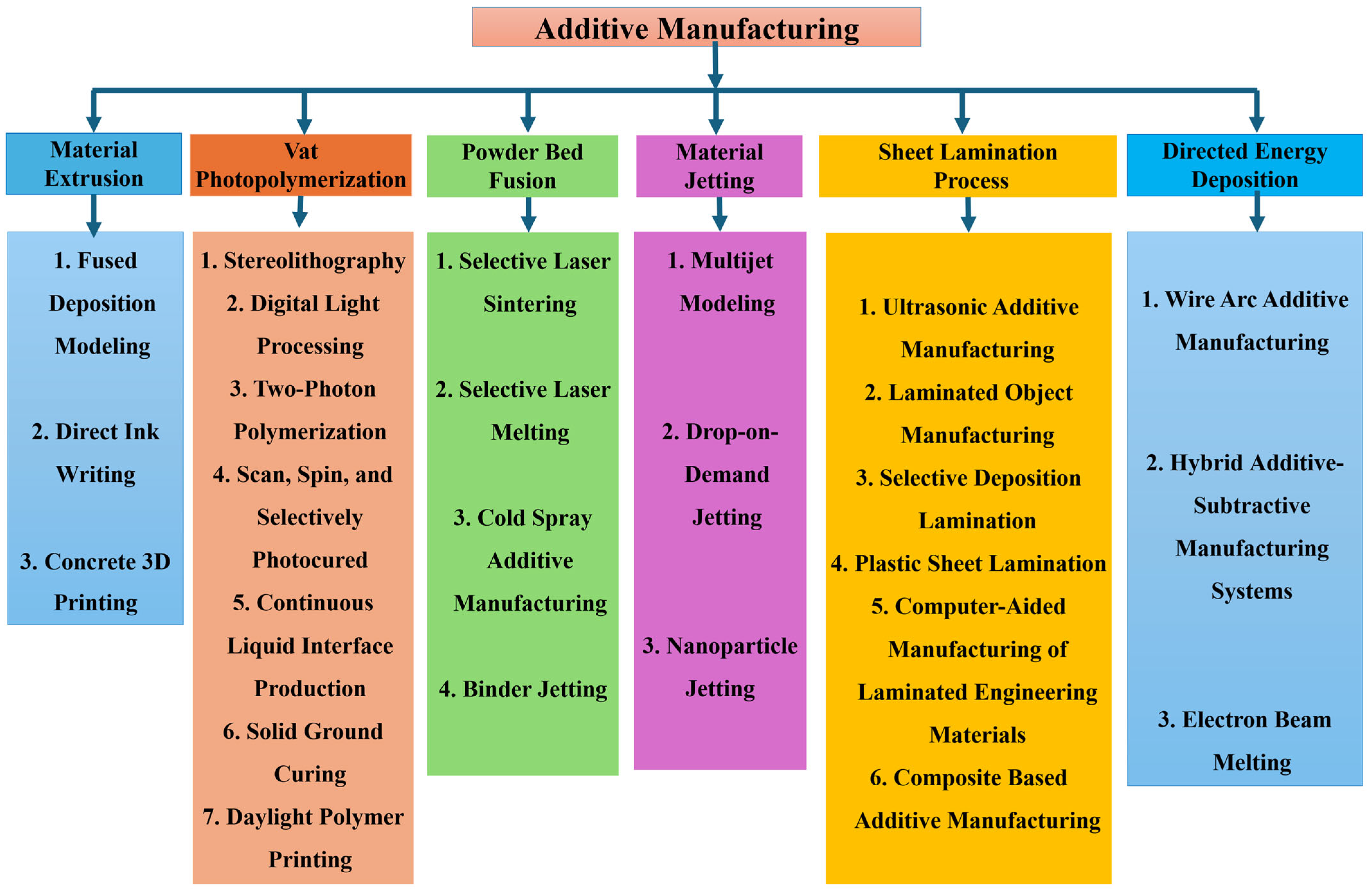
Figure 1. Classification of additive manufacturing processes [4].
Jmmp 09 00269 g001
Figure 2. Types of materials used for sustainable green additive manufacturing techniques.
Jmmp 09 00269 g002
Figure 3. Schematic of Fused Deposition Modeling [17].
Jmmp 09 00269 g003
Figure 4. Schematic of Direct Ink Writing [21].
Jmmp 09 00269 g004
Figure 5. Concrete 3D Printing process [25].
Jmmp 09 00269 g005
Figure 6. (a) Fabrication process of stereolithography. (b) Overview of stereolithography [29].
Jmmp 09 00269 g006
Figure 7. Schematic representation of two-photon polymerization [29].
Jmmp 09 00269 g007
Figure 8. (a) Flow diagram of printing procedure. (b) Scheme of DLP 3D printing process [34].
Jmmp 09 00269 g008
Figure 9. Schematic of Scan, Spin, and Selectively Photocured (3SP) [38].
Jmmp 09 00269 g009
Figure 10. Schematic of Continuous Liquid Interface Production (CLIP) [29].
Jmmp 09 00269 g010
Figure 11. Schematic of Solid Ground Curing (SGC).
Jmmp 09 00269 g011
Figure 12. Schematic of Daylight Polymer Printing (DPP) [51].
Jmmp 09 00269 g012
Figure 13. Schematic of SLS from 3D CAD design to the laser sintering process [21].
Jmmp 09 00269 g013
Figure 14. Schematic of SLM process flow diagram [58].
Jmmp 09 00269 g014
Figure 15. Schematic of Cold Spray Additive Manufacturing (CSAM) [66].
Jmmp 09 00269 g015
Figure 16. Schematic of binder jetting process [21].
Jmmp 09 00269 g016
Figure 17. Schematic of Multijet Modeling (MJM) [77].
Jmmp 09 00269 g017
Figure 18. Schematic of drop-on-demand jetting [21].
Jmmp 09 00269 g018
Figure 19. Schematic of NPJ process [83].
Jmmp 09 00269 g019
Figure 20. Schematic of Ultrasonic Additive Manufacturing (UAM) [87].
Jmmp 09 00269 g020
Figure 21. Schematic of Laminated Object Manufacturing (LOM) [21].
Jmmp 09 00269 g021
Figure 22. Schematic of Selective Deposition Lamination [51].
Jmmp 09 00269 g022
Figure 23. Schematic of Plastic Sheet Lamination [97].
Jmmp 09 00269 g023
Figure 24. Schematic of Composite-Based Additive Manufacturing: (a) with pre-impregnated fiber filament; (b) with fiber impregnation in the print head (CBAM) [104].
Jmmp 09 00269 g024
Figure 25. Schematic of Wire Arc Additive Manufacturing (WAAM) [105].
Jmmp 09 00269 g025
Figure 26. Schematic of hybrid additive–subtractive manufacturing [109].
Jmmp 09 00269 g026
Figure 27. Schematic of the Electron Beam Additive Manufacturing process, where 1 is an object building platform; 2, a feed container; 3, a deposition unit; 4, a power source [114].
Jmmp 09 00269 g027
Figure 28. Design of sustainability for additive manufacturing.
Jmmp 09 00269 g028
Figure 29. Impacts of additive manufacturing on environmental sustainability [15].
Jmmp 09 00269 g029
Table 1. Comprehensive overview of additive manufacturing technologies.
AM CategoryTechnologyAdvantagesLimitationsMaterials UsedApplicationsReferences
Material ExtrusionFDMLow cost, wide range of materials, simple and accessible technology.Visible layer lines, lower resolution, anisotropic part strength.Thermoplastic filaments: PLA, ABS, PETG, nylon, PC, ASA.Rapid prototyping, manufacturing tooling, medical models, custom prosthetics.[19,117]
DIWExtremely versatile material range, can print functional materials.Slower process, resolution limited by nozzle size, requires post-processing.Viscous inks: ceramic slurries, polymer/elastomer inks, hydrogels, composite inks.Bioprinting, flexible electronics, soft robotics, microfluidics, aerospace components.[22,23,118]
Concrete 3D PrintingAbility to build large-scale structures quickly, reduced labor costs, design freedom for complex shapes.Rough surface finish, complex material science, structural limitations without reinforcement.Custom mortar (cement, sand), chemical additives, reinforcing fibers (glass, steel, polymer).Construction (housing, shelters), infrastructure (bridges), custom urban furniture.[25,26,119]
Vat PhotopolymerizationSLAExcellent surface finish, high detail and accuracy, isotropic properties.Materials can be brittle and expensive, messy resin handling, requires post-curing.UV-curable liquid resins (monomers, oligomers, photoinitiators).Soft robotics, sensors, medical implants, microfluidic devices, high-detail prototypes.[29,30,120]
DLPFaster than SLA, high resolution.Similar to SLA (brittle materials, post-curing), resolution fixed by projector pixels.Photopolymers (acrylates, epoxies), specialty and hybrid resins, metal-printing resins.Smart/biomimetic devices, sensors, 4D printing (shape-memory polymers).[33,121]
2PPExtremely high, submicron resolution for creating nano-scale features.Very slow process, extremely small build volume, very expensive equipment.Laser-activated resins (acrylate, epoxy, PDMS-like).Micro-robotics, micro-lenses, biosensors, microneedles, photonic crystals.[35,122]
3SPVery high throughput and speed for a resin-based process, reliable for production.Proprietary technology and materials, less common than SLA/DLP.Proprietary UV-curable photopolymer resins.High-throughput production, medical devices, master patterns for casting.[39,123]
CLIPExceptionally fast printing speed, excellent material properties due to dual-cure process.Proprietary technology, expensive materials and machines, limited build volume.Dual-cure resins (rigid/flexible/elastomeric polyurethanes, silicones).Mass customization (shoe midsoles), end-use automotive parts, medical/dental implants.[43,44]
SGCNo need for support structures (used wax), good dimensional stability.Obsolete technology; extremely complex, large, wasteful, and expensive.UV-curable photopolymer resin, low-melting-point wax, and masking consumables.Rapid prototyping of large concept models and master patterns.[47,124]
DPPUses safer, lower-intensity visible light; low-cost hardware.Slower curing times than UV-based methods; more limited material selection.Proprietary photopolymers that cure with visible light (firm, tough, flexible, castable).Quick prototyping, dental models, jewelry master patterns, hobbyist/educational models.[50]
Powder Bed FusionSLSNo support structures needed, excellent for complex geometries, produces strong, functional parts.Rough surface finish, requires significant powder removal post-processing, higher cost.Polymer powders (PCL, PEEK), bioactive materials, metals, and composites.Tissue engineering, medical/dental implants, custom healthcare equipment.[48]
SLMCreates fully dense, high-strength metal parts with high accuracy.Very expensive, requires support structures, risk of thermal stress/warping, powder handling hazards.Metal powders: titanium, Inconel, steels, aluminum, cobalt–chrome, precious metals.Aerospace parts, medical/dental implants, high-performance industrial components.[56,57]
CSAMLow-temperature solid-state process, can bond dissimilar materials, great for repair and coatings.Lower resolution, parts have some porosity, geometry is limited to line-of-sight spraying.Ductile metal powders/alloys (aluminum, copper, steel, titanium, Inconel).Repair/restoration of industrial parts (aerospace), manufacturing large components.[67,125]
Binder JettingFast, scalable, can print in full color, no support needed, lower cost for metal parts.Green parts are fragile, requires extensive post-processing, which causes shrinkage.Powder and binder system (metal, ceramic, sand, or gypsum powders).Serial production (metal), technical components (ceramic), full-color models, sand casting molds.[70,71]
Material JettingMJMExcellent accuracy, smooth surface finish, can print multi-material and multi-color parts.Materials can be expensive and have limited mechanical/thermal properties; requires support removal.UV-curable photopolymer builds resins and a separate wax-based or gel-like support material.High-fidelity prototypes, medical/dental models, jewelry patterns, manufacturing jigs.[79,80]
DoD JettingHigh precision, extremely broad material compatibility if viscosity is correct.Can be slow, potential for nozzle clogging, requires careful fluid property control.Inks, photopolymers, wax, conductive inks, ceramic slurries, and bio-inks.Industrial graphics, high-fidelity prototypes, printed electronics, bioprinting.[85,126]
NPJHigh precision and detail with robust end-use materials (metals/ceramics).Limited to materials available in nanoparticle suspension, relatively new technology.Suspension of metal (steel, copper) or ceramic (zirconia, alumina) nanoparticles in a liquid.Small, complex parts for medical/dental (implants), aerospace/electronics (connectors).[84,127]
Sheet LaminationUAMLow-temperature, solid-state process; can bond dissimilar metals and embed electronics.Limited to foils/tapes, cannot create certain internal geometries, residual stress can be an issue.Thin metal foils/tapes (aluminum, copper, nickel) and embedded components.“Smart structures” with embedded sensors, heat exchangers, custom medical implants.[90,91]
LOMFast and cheap for large parts, creates stable, wood-like objects.Tedious manual post-processing, poor material properties (porous, weak).Sheet materials with adhesive backing, primarily paper but also plastics, composites, foils.(Obsolete) rapid prototyping of large conceptual models and patterns for casting.[92,93]
SDLLow cost, safe, can produce full-color, realistic models directly from the machine.Layer lines are very visible; parts are brittle and susceptible to moisture without sealing.Standard office paper, water-based liquid glue, and CMYK ink.Full-color concept models, architectural/GIS maps, educational visual aids.[128,129]
PSLCreates large, durable, solid plastic parts quickly and cost-effectively.Stair-stepping effect is prominent; resolution is limited by sheet thickness.Thermoplastic sheets (PVC, PS, ABS) that self-bond when heated and pressed.Large, durable prototypes, ergonomic mock-ups, and master patterns for manufacturing.[86,98]
CAM-LEMCan create complex, multi-material, and functionally graded ceramic/metal parts.Requires burnout and sintering post-processing, which can cause shrinkage and distortion.“Green tapes” of ceramics (alumina, zirconia), metals (steels), or composites.High-value ceramic/multi-material parts for aerospace, energy, electronics, and medicine.[100,101]
CBAMProduces very strong, stiff, and lightweight parts by embedding continuous fibers.Fiber placement is limited by geometry, higher cost than standard FDM.Thermoplastic matrix (nylon) combined with continuous reinforcing fibers (carbon, fiberglass, Kevlar).Strong functional parts: jigs, fixtures, robotic tooling, automotive/aerospace components.[104]
Directed Energy DepositionWAAMVery high deposition rate, ideal for building large metal parts, uses low-cost welding wire.Low resolution and poor surface finish, requires extensive finish machining.Standard metal welding wire: steels, titanium, Inconel, aluminum, bronze alloys.Large structural parts for aerospace (ribs), maritime (propellers), oil and gas (flanges).[107,108]
Hybrid ManufacturingCombines the freedom of additive with the precision of subtractive in one machine; highly efficient.Extremely high capital cost, complex programming and operation.High-performance metals in powder or wire form (steels, superalloys, titanium alloys).Repair of high-value parts, advanced tooling, custom medical implants.[111,112]
EBMExcellent for reactive metals like titanium, produces parts with low residual stress in a vacuum.Requires vacuum environment, rougher surface finish than SLM, limited material selection.High-performance, conductive metals: titanium, cobalt–chrome, Inconel, copper.Medical implants, lightweight aerospace/defense components.[115,116]
Table 2. Comparison of common sustainable materials in AM.
MaterialSource and TypeAM ProcessMechanical PropertiesReferences
PLACorn starch, sugar cane (bio-based polyester)FDM, SLAModerate strength, high stiffness, brittle.[98,134,135]
PHABacterial fermentation (bio-polyester)FDM Like polypropylene, more flexible than PLA.[136,137,138]
PCLPetroleum-based (biodegradable polyester)FDMLow melting point, highly flexible, tough.[139,140,141]
Wood CompositesPLA/PHA mixed with wood, cork, coffee, hemp fibers.FDMLower tensile strength, aesthetic finish, abrasive to nozzles.[142,143,144]
Recycled PET (rPET)Post-consumer plastic bottles.FDMStrong, durable, high thermal resistance.[145,146,147]
Table 3. Comprehensive comparative energy sources of AM processes.
AM CategorySpecific ProcessEnergy SourceReferences
Material ExtrusionFDMNozzle and Bed[151,152]
DIWMechanical Dispenser[153,154]
Concrete 3D Pump and Motor System[155,156]
Vat PhotopolymerizationSLAHigh-Precision UV Laser[157,158]
DLPUV Projector [159,160]
2PPFocused Femtosecond Laser[161]
3SPLow-Power Laser and High-Power UV Flash Lamp[162]
CLIPUV Projector and Oxygen-Permeable Membrane[42]
SGCHigh-Power UV Lamp, Wax Heater, Milling Spindle[163]
DPPLED Array and Screen[121]
Powder Bed FusionSLSCO2 Laser, Infrared Heaters[164]
SLMHigh-Power Fiber Laser[165]
EBMElectron Beam[166]
Binder JettingPiezoelectric Inkjet Head[167]
CSAMHeated, High-Pressure Gas[168]
Material JettingMJMPiezoelectric Printhead[169]
DoDPiezoelectric Printhead[81]
NPJInkjet Head, High-Temperature Chamber[85]
Sheet LaminationUAMUltrasonic Welder, CNC Spindle[170]
LOMCO2 Laser, Heated Roller[167]
SDLInkjet Head, Heated Roller[158]
PSLThermal Cutter, Heated Plate[154]
CAM-LEMLaser Cutter[99]
CBAMNozzle[102]
Directed Energy DepositionWAAMElectric Welding Arc [171]
Hybrid WAAM Source and CNC Spindle[109]
Table 4. Challenges and solutions for integrating sustainable materials in AM.
Material CategoryKey ChallengesMaterial-Level SolutionsProcess-Level SolutionsReferences
Biopolymers (PLA, PHA, etc.)Narrow processing window
Thermal degradation
Poor mechanical properties (brittleness)
Plasticizers: Increase flexibility and lower processing temp.
Impact modifiers: Enhance toughness
Nucleating agents: Control crystallization for better strength.
Precise temperature control systems
Optimized print speed and cooling
Use of enclosed, heated build chambers.
[48,82]
Recycled Polymers (rPET, rABS)Batch-to-batch inconsistency
Reduced melt viscosity
Presence of contaminants
Hydrolytic degradation (moisture)
Drying: Thoroughly dry feedstock to prevent hydrolysis
Blending: Mix batches to homogenize properties
Chain extenders: “Repair” polymer chains to restore melt strength
Filtration: Remove solid contaminants during filament extrusion.
Advanced sorting and cleaning of recycle
In-line rheology sensors for real-time process adjustment
Wider nozzle diameters to reduce clogging risk.
[146,189]
Natural Fiber CompositesNozzle clogging due to fiber agglomeration
Poor fiber–matrix interfacial adhesion
Abrasive wear on hardware
Moisture absorption by fibers
Coupling agents: Promote bonding between fibers and polymer matrix
Fiber surface treatment: Modify fiber surfaces for better compatibility
Optimized compounding: Ensure uniform fiber dispersion in the filament.
Use of hardened steel or ruby-tipped nozzles
Larger nozzle diameters (>0.5 mm)
Reduced retraction settings to prevent clogging
Slower print speeds to reduce shear stress.
[7,190]
Table 5. A comparative analysis of manufacturing scalability.
ParameterTraditional Mass ProductionLab-Scale Green AMIndustrial-Scale Green AM Challenge
ThroughputVery high (e.g., 100–1000 s of parts/hour)Very low (e.g., <1 part/h)Must increase deposition rates and minimize failures to approach mass production speeds.
Material ConsistencyHigh (standardized, certified material grades)Low to medium (highly variable recycled or novel bio-feedstocks)Requires robust supply chains and feedstock qualification standards.
Process ControlHighly automated and stable; set-and-forget process.Manual, iterative tuning for each new material batchDemands real-time, in situ monitoring and automated feedback loops to manage material inconsistency.
Post-ProcessingMinimal and often automated (e.g., robotic part removal)Manual, labor-intensive, and time-consumingNeeds significant investment in robotic systems for support removal, finishing, and handling to prevent bottlenecks.
Supply ChainMature, global, and reliableLocalized and often unstableMust establish resilient, large-scale supply chains for certified recycled and biomaterials.
Cost Per PartVery lowVery highMust reduce costs through automation, speed, and material efficiency to become competitive.
Table 6. Strategies to overcome mechanical deficiencies in sustainable AM.
Mechanical ChallengePrimary CauseMaterial-Level SolutionsProcess/Design/Post-Processing SolutionsReferences
Anisotropy (Weak Z-axis)Poor interlayer thermal fusion.Use polymers with better melt flow.
Additives to lower melt viscosity.
Process: Increase nozzle temp, use heated chamber, reduce cooling fan speed.
Design: Optimize part orientation to align layers with non-critical stress paths.
[195,196]
Low Strength and StiffnessInherently weaker polymer backbone.Composites: Add carbon, glass, or natural fibers.
Blending: Mix with higher-strength polymers.
Process: Optimize infill density and pattern.
Design: Use topology optimization and internal lattices to create stiff, efficient geometries.
[197,198]
Porosity and Voids- Imperfect material flow.
- Moisture in filament.
Ensure uniform filament diameter.
Use additives for stable melt rheology.
Process: Meticulously dry feedstock before printing.
Post-Processing: Use infiltration with resins (e.g., epoxy) or surface sealing (vapor smoothing).
[199,200]
Low Thermal ResistanceAmorphous nature and low glass transition temp (Tg) of many biopolymers.Blending: Mix with high-temp polymers (e.g., PC, ABS).
Additives: Use nucleating agents to increase crystallinity.
Post-Processing: Anneal parts to increase crystallinity, which raises the Heat Deflection Temperature (HDT).[201]
Table 7. Comparative cost analysis of traditional vs. sustainable AM feedstocks.
Cost FactorTraditional PolymersSustainable Feedstocks
Upfront Material CostLow. Benefits from mature, high-volume petrochemical supply chains.High. Driven by costs of collection, sorting, cleaning, and smaller production scale.
R&D and Formulation CostMinimal. Well-established, standardized grades.High. Requires investment in additives and compounding to overcome degradation and ensure consistency.
Internal Waste ManagementCost. Scrap material is often a waste stream requiring disposal fees.Opportunity. Scrap can be re-granulated and recycled in-house, turning waste into a resource.
Regulatory and Compliance CostIncreasing. Facing growing pressure from plastic taxes, EPR schemes, and carbon pricing.Lower/favorable. Aligned with emerging environmental regulations, potentially eligible for subsidies or tax breaks.
Brand and Market PerceptionNeutral to negative. Increasing consumer awareness of plastic pollution can be a brand risk.Positive. Offers a strong marketing narrative around sustainability, innovation, and circularity.
End-of-Life LiabilityHigh. Contributes to landfill burden and environmental pollution, a long-term liability.Low. Designed for circularity, reducing long-term environmental and financial liability.
Overall JustificationBased purely on low initial purchase price.Based on a lifecycle cost, including waste reduction, brand value, and futureproofing.
Table 8. Emerging sustainable materials for additive manufacturing.
Material ClassExamplesKey AdvantagesPrimary ChallengesReferences
Advanced Bio-PolymersPHAs, lignin-based polymersBiodegradability (PHA), valorization of waste (lignin), non-food feedstock.Thermal instability, brittleness, high cost, complex processing.[204,205]
Bio-ResinsAlgae-derived oligomersFast-growing feedstock, CO2 sequestration, potential for high-resolution printing (SLA/DLP).Lower mechanical properties than petrochemical resins, long-term stability.[206]
Nano-Bio-CompositesNanocellulose-reinforced PLAExtremely high strength-to-weight ratio, significant property enhancement at low filler content.Difficult to disperse uniformly, moisture sensitivity.[207,208]
Agricultural Waste CompositesRice husk, hemp fiber, or coffee ground fillersVery low cost, negative carbon footprint (waste valorization), localized supply chains.Inconsistent properties, poor fiber–matrix adhesion, moisture absorption.[209,210]
Living MaterialsMycelium, engineered bacteriaSelf-growing, self-healing potential, fully home-compostable, extremely low embodied energy.Very slow growth rates, limited structural properties, process control and sterility.[211]
Table 9. Future research directions for integrated SGAM challenges.
ParameterKey ChallengesFuture Research and Development Directions
Material PerformanceAnisotropy and weak interlayer bonding
Lower thermal and mechanical properties
Unknown long-term aging behavior
Development of self-healing and functional nanocomposites
Computational models for predictive material aging and performance
Advanced DfAM techniques to optimize geometry for weaker materials.
Circular RecyclingContamination of recycled feedstocks
Difficulty in separating multi-material parts
Downcycling of materials during mechanical recycling
Establishing industry standards for design for recycling
Scaling up chemical recycling for mixed polymer waste
Implementing digital material passports for automated sorting
Energy EfficiencyHigh embodied energy in some feedstocks
Inefficient thermal management in printers
Energy-intensive post-processing steps
Creation of energy-aware slicing software and build processors
Development of low-energy processing (e.g., LED curing, microwave sintering)
Integration of AM systems with renewable energy and smart grids
Disclaimer/Publisher’s Note: The statements, opinions and data contained in all publications are solely those of the individual author(s) and contributor(s) and not of MDPI and/or the editor(s). MDPI and/or the editor(s) disclaim responsibility for any injury to people or property resulting from any ideas, methods, instructions or products referred to in the content.