Article

Hybrid Manufacturing and Experimental Testing of Glass Fiber Enhanced Thermoplastic Composites

School of Engineering & Built Environment, Anglia Ruskin University, Chelmsford CM1 1SQ, Essex, UK
*
Author to whom correspondence should be addressed.
J. Manuf. Mater. Process. 2019, 3(4), 96; https://doi.org/10.3390/jmmp3040096
Submission received: 29 October 2019 / Revised: 25 November 2019 / Accepted: 27 November 2019 / Published: 2 December 2019
(This article belongs to the Special Issue Additive Manufacturing and Device Applications)

Abstract

:
Additive Manufacturing (AM) is gaining enormous attention from academic and industrial sectors for product development using different materials. Fused Deposition Modelling (FDM) is a popular AM method that works with thermoplastics. This process offers benefits of customisation both in terms of hardware and software in the case of desktop-based FDM systems. Enhancement of mechanical properties for the traditional thermoplastic material is a widely researched area and various materials have been added to achieve this goal. This paper focuses on the manufacture of glass fiber reinforced plastic (GFRP) composites using Hybrid Fused Deposition Modelling (HFDM). Commonly available polylactic acid or polylactide (PLA) material was inter-laced with 0.03 mm thick glass fiber sheets to manufacture GFRP products followed by tensile testing. This was done to investigate whether adding more layers increases the tensile strength of the GFRP products or not. Furthermore, the maximum number of glass fiber layers that can be added to the 4 mm thick specimen was also identified. This was done to demonstrate that there is an optimal number of glass fiber layers that can be added as after this optimal number, the tensile strength start to deteriorate. Microstructural analysis was undertaken after tensile testing followed by ultrasonic testing to assess the uniformity of the GFRP composites.

1. Introduction

Composites have taken a large portion of the manufacturing market due to their properties, most notably, their high strength to weight ratio. This is further augmented by the possibility of tailoring the mechanical properties by modifying the process parameters. However, these modifications are mostly based on trial and error methods and ensuring consistent properties is crucial for wider applications [1,2,3,4]. For composites, two or more materials are combined together with the aim of enhancing the overall properties of the final product. Their mechanical properties can be engineered, preferably by adjusting the volume or mass fraction of the constituents or completely replacing one constituent by another suitable one. The study of the bonding interface of these constituents and subsequent fracture mechanisms are a widely researched area and allow for improving mechanical properties [5,6,7,8,9]. Plastics are one of the most popular materials that are commonly used for composite development as they are cost-effective and readily available. In this context, thermoset and thermoplastics are two types that are commonly used for the manufacture of composites. The molding process is a popular choice for the manufacture of thermoset composites (materials that undergo a chemical reaction and transform from a liquid into a solid). This work, however, focuses on additive manufacturing (AM) methods and more specifically, Fused Deposition Modelling (FDM) that is one of the most common methods for the manufacture of thermoplastics. These materials are thermo-formable (softening of the thermoplastic material when heated) and recyclable, that makes them more valuable for industries. FDM is being used extensively for direct digital manufacturing applications due to the easy access and low-cost of personal 3D printers that can work with a wide variety of materials. Two commonly used materials for FDM are acrylonitrile butadiene styrene (ABS) and polylactic acid or polylactide (PLA). Both have their pros and cons that should be considered before usage. PLA is a bio-degradable material derived from renewable resources such as corn starch or sugarcane. It is one of the most popular bioplastics, used for many applications ranging from plastic cups to medical implants. On the other hand, ABS is also quite popular in the injection molding arena and its applications range from LEGO toys and electronic housings to bumper parts for automobile use. For these thermoplastics, a high strength to weight ratio is a major aspect as it allows applications in various industrial sectors, e.g., aerospace, automotive and medical. Therefore, efforts have been made to enhance the strength of these thermoplastic materials while keeping them lightweight. FDM, being an AM method, offers benefits of design freedom, reduced costs and lead times etc., which further improves its applicability for engineering applications.
Existing literature shows limited innovation in terms of enhancing the capabilities of the FDM process but rather focuses on the development of fiber reinforced materials that can be easily printed. Ning et al. [10] developed carbon fiber filled ABS filaments from plastic pellets and carbon fiber powder with varying fiber content for FDM process. Carbon fiber reinforced plastic (CFRP) composites were manufactured to experimentally investigate the effect of adding carbon fiber on the mechanical properties of the FDM-printed parts. The experimental result showed enhancement of tensile and flexural properties of the CFRP composites compared to pure ABS. Furthermore, they also showed that the tensile properties initially increased but then deteriorated drastically highlighting an optimal carbon fiber content in the ABS filaments. Liu et al. [11] investigated the tensile and flexural properties of PLA composites with different additives i.e., wood, ceramic, copper, aluminium and glass fiber manufactured by FDM. They noticed that PLA composites have similar or increased mechanical properties compared to parent PLA. Coppola et al. [12] studied the effect of adding hemp powder (diameter between 75 and 180 µm) via melt-compounding into PLA 4043D at three different volume percentages (1, 3 and 5%). PLA/hemp composites exhibited higher elastic modulus compared to PLA and showed increase with increase in the hemp powder content. Tao et al. [13] investigated the development of wood flour (WF)-filled polylactic acid (PLA) composite filaments for FDM. They concluded that adding WF of 5 wt% has no effect on the melting temperature of the PLA and it also increased the tensile stress of the WF-PLA composites compared to virgin PLA. Pantanwala et al. [14] discussed the 3D printing of carbon nanotube-polylactic acid (CNT-PLA) composites with FDM. CNTs were added at 0.5%, 2.5%, and 5% (w/w) CNT loadings and they showed that the Young’s modulus increased the by 30% at 5% CNT loading. However, this content of CNT also resulted in reduced tensile strength and overall toughness of the resulting FDM products. Gkartzou et al. [15] used FDM for the manufacture and experimental testing of PLA/lignin composites based on different lignin weight ratios. They observed changes in the mechanical properties with the composites becoming more and more brittle with increasing lignin content with the 20% wt. lignin product too brittle for tensile testing. FDM is also quite popular for printing on textiles to manufacture functional composites. Sanatgar et al. [16] investigated the effect of FDM process parameters (extruder temperature, platform temperature and printing speed) on the adhesion properties of polymers and nanocomposites for textiles. They found that PLA and its composites had high adhesion force to PLA fabrics due to their compatibility. The work done by Eutionnat-Diffo et al. [17] showed the adhesion characteristics of PLA filaments deposited onto polyethylene terephthalate (PET) textiles through 3D printing. The PLA/PET composites demonstrated lower deformation compared to virgin PET showcasing better dimensional stability, higher stiffness and lower flexibility.
This clearly shows the capability of the FDM process in terms of manufacturing plastic-based composites. However, the literature involves pre-processing to manufacture the filament material before printing. This aspect can be changed with the process of Hybrid Fused Deposition Modelling (HFDM) that allows the addition of additive layers that gets adhered to the extruded material. The process has been explained in detail in our previous work [18] where ABS/copper mesh composites were manufactured and experimentally tested. We also showed that increasing the number of Cu layers linearly increase the tensile strength of the Cu/ABS products compared to parent ABS. The next section will provide a breakdown of activities undertaken to manufacture the metal/plastic composites.

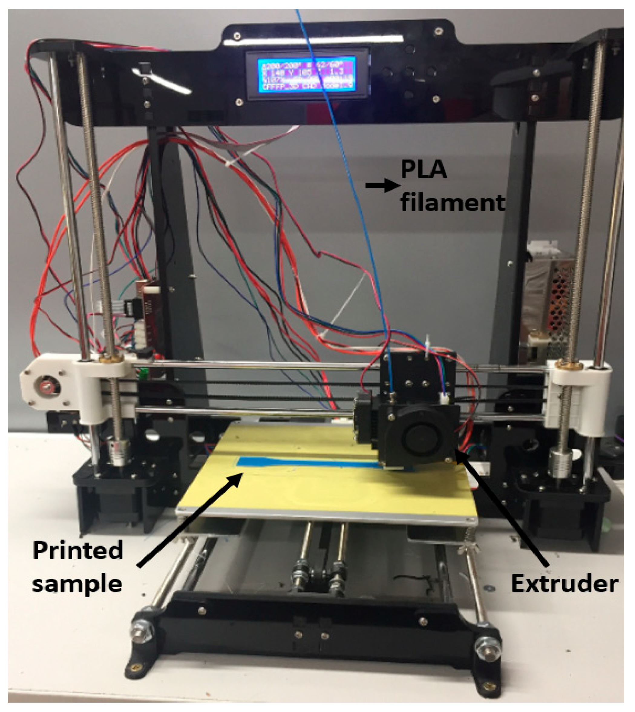
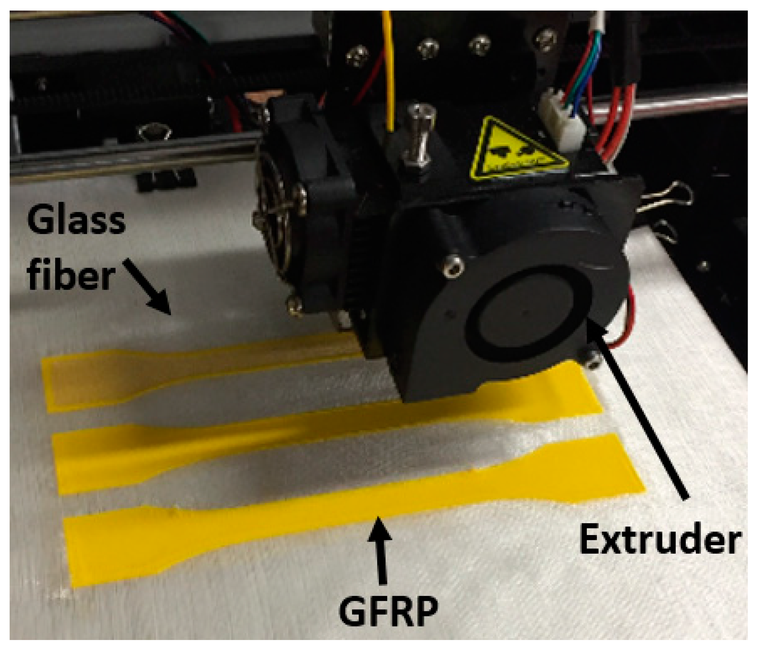
2. Materials and Manufacturing Processes

The process of HFDM was broken down into steps for practicality. A low-cost DIY desktop 3D printer called Anet A8 3D printer (from Shenzen Anet Technology Company Limited, Hong Kong) was used for the manufacture of products based on British and International standards. The printer had a work envelope of 220 mm × 220 mm × 250 mm (X × Y × Z) and an extruder nozzle diameter of 0.4 mm (Figure 1). PLA (RS PRO filament of 1.75 mm diameter from RS Components, Corby, UK) and thin glass fiber sheets (from Easy Components, Stoke-on-Trent, UK) were used for product development. The glass fiber sheets had a woven fiber mesh with an aperture of 0.22 mm and fiber diameter of 0.03 mm. The 3D CAD model of the part to be built was sent to an open source 3D printer slicing software package called Ultimaker Cura 4.3.0 that began the build operation. The part was built at a speed of 60 mm/s with a layer thickness of 0.2 mm. PLA was printed at 200 °C with the bed temperature set at 60 °C as shown in Figure 1. The glass fiber layers were added to the parts by utilising the ‘Pause at height’ option in the CURA 4.3.0 software and then resuming the operation to manufacture glass fiber reinforced plastic (GFRP) products as shown in Figure 2 and Figure 3. For improved adhesion between plastic and the thin glass fiber layers, the number of shells were increased from two to three, infill density was set at 100% and the infill pattern is selected as ‘Cubic’ in the Cura 4.3.0 software. There are other options that can be considered e.g., choosing a different infill pattern (such as quarter cubic, triangles, concentric, zig-zag), increasing the thickness of the top as well as bottom layers, layer thickness, raster angle and build orientation [19,20]. Optimisation of 3D printing parameters is a complex process; therefore, the build process was kept simple to ensure consistent results in a timely manner. For statistical accuracy, a total of three specimens were tested for all the different materials and configurations.

3. Experimental Methodology

3.1. Tensile Testing

The products for tensile testing were manufactured based on BS EN ISO 527-2:2012 [21]. The dimensions of the specimens are given in Figure 4. Previous work has shown the capability of HFDM in producing products with higher strength, therefore, this test is being conducted to analyse the extent of increase in tensile strength of the FDM-printed parts upon the addition of glass fiber layers. The GFRP composites are manufactured by increasing number of glass fiber layers (one, two, three and so on). This has been done to ensure that an optimal number of glass fiber layers can be identified for the 4 mm thick dog-bone specimen as after this optimal number, the tensile strength start to deteriorate. The overall thickness of the specimens was kept at 4 mm ± 0.2 mm (the precision of the printer). Pure PLA specimens were made according to the methodology discussed in Section 2 and the GFRP were made by pausing the build operation. According to the Cura 4.3.0 software, 20 layers (layer thickness of 0.2 mm) are required to manufacture the 4 mm thick dog-bone specimen. An additional four layers were added to the specimen as ‘raft’ type build plate adhesion was selected (amounting to 24 total layers). This will keep the specimen adhered to the build plate and will minimize the effect of warping. The first four layers are for the raft and the remaining 20 build the 4 mm thick specimen. GFRP composites were manufactured with increasing layers of copper mesh (1, 2, 3 and so on until 15) while keeping the overall thickness to 4 mm ± 0.2 mm. For example, in case of a single layered composite, one glass fiber layer was placed at 50% of the overall thickness of the specimen and for a double layered composite, two glass fiber layers were placed at 40% and 80%. For the addition of 15 layers, the same calculations were carried out (relevant layer number of the CAD model for the fiber layer insertion = (20/16) × 1 = 1.25 so it is considered as layer 1. The layer numbers are calculated in this manner. Values such as 1.25 and 2.5 were considered as 1 and 2, respectively whereas the values such as 3.75 and 8.75 were rounded off to 4 and 9, respectively. There layer numbers are then used to calculate percentage of product completion. The percentage completion for the addition of a single layer of glass fiber = (1/20) × 100% = 5%).
The tensile testing was carried out using a Universal Tensile Testing Machine at a crosshead speed of 1.5 mm/s according to the standard. The glass fiber layers were added without any treatment and the programming was not modified to accommodate the 0.03 mm thin layers. This effect has been analysed by measurements of thickness and mass for the GFRP composites in Section 4.1.

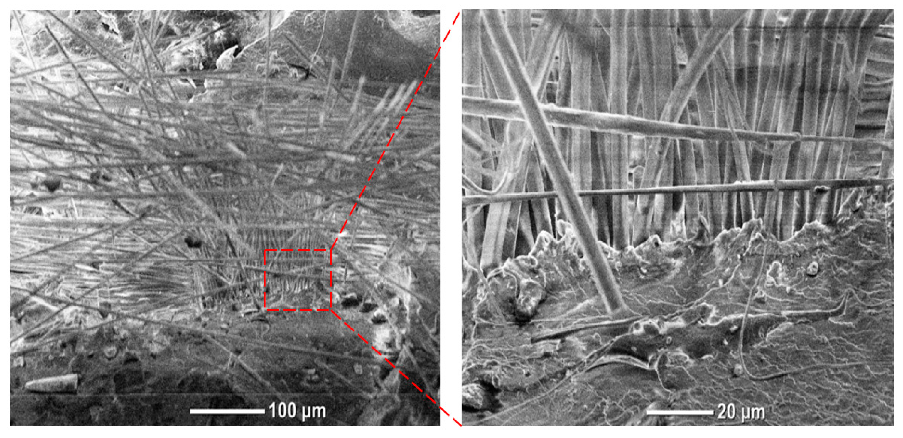
3.2. Microstructural Analysis

A JCM-5000 NeoScope™ table top scanning electron microscope (JEOL, Boston, USA) was used to analyse the fractured surfaces of the tensile tested PLA and GFRP products. This analysis was conducted to investigate the adhesion quality and porosity of the products. The joining of glass fibers using the adhesion properties of the extruded PLA is an interesting prospect and this test allowed to investigate how the PLA layers bonded with the glass fibers as well as other PLA layers that had been printed before. The fractured surfaces were carefully cut to size to fit atop the platform of the scanning electron microscope (SEM). They were analysed without any surface treatment to avoid contamination. This test helped in understanding the bond interface between the two materials (PLA and glass fiber) as the layers of glass fibers increase in the 4 mm thick specimens.

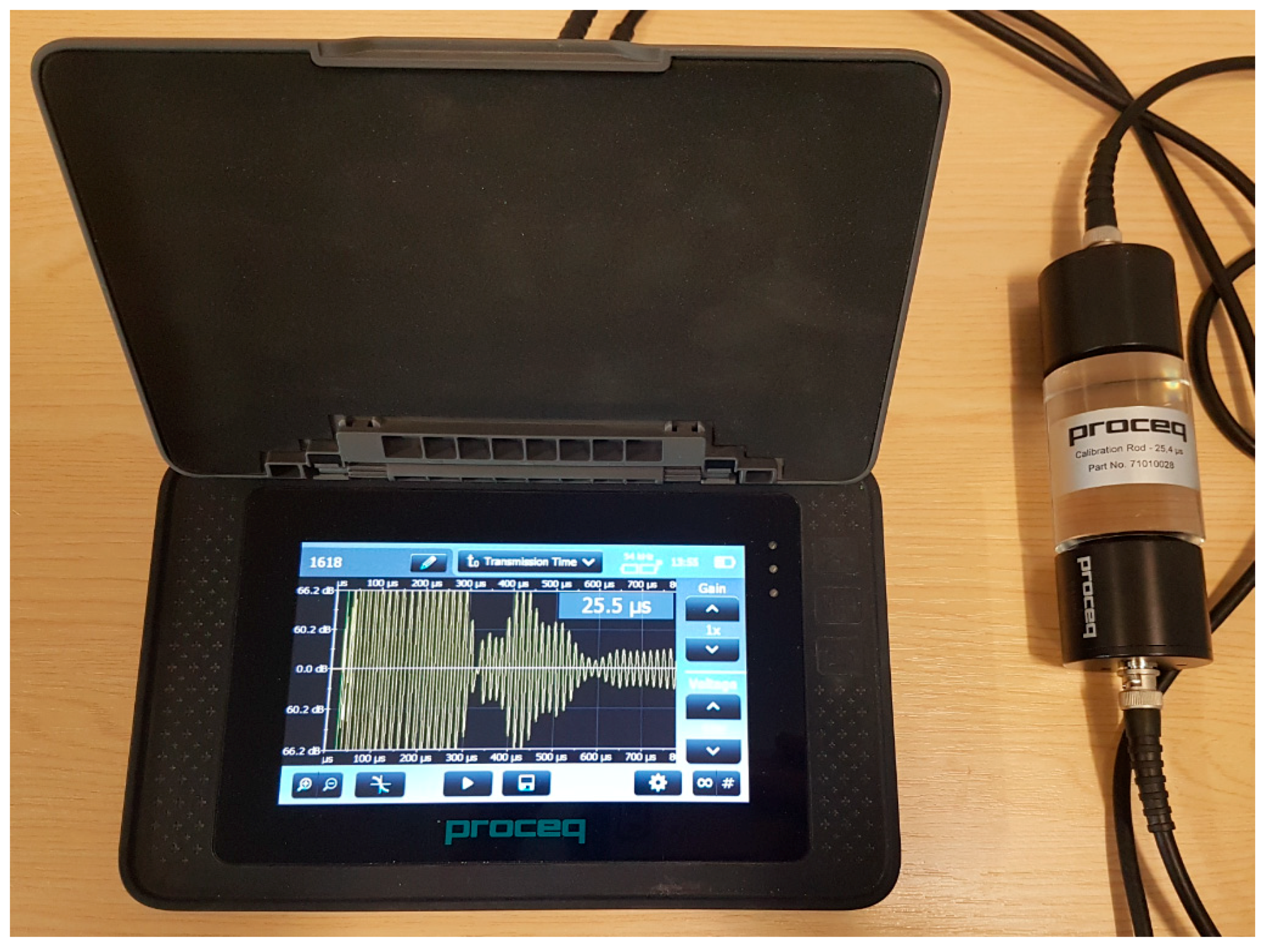
3.3. Ultrasonic Testing

Non-destructive testing (NDT) techniques are extremely popular in engineering inspection and evaluation as they assess the integrity of a product without destroying it so that it can be used afterwards. Ultrasonic testing is a common NDT method and works on the transmission of ultrasonic waves through a test piece. For this work, a Proceq PUNDIT® PL-200 device (Proceq, Schwerzenbach, Switzerland) was used. It comprises two transducers (54 kHz) with a measuring resolution of 0.1 μs. This is a standard instrument for ultrasonic pulse velocity testing as shown in Figure 5. Couplant gel was used on the traducers as it facilitates the transmission of ultrasonic energy into the test piece. There are two methods of receiving the ultrasound waveform i.e., reflection and attenuation. In the former, only one transducer performs the sending and receiving whereas in the latter, two transducers are used. Attenuation method was used in this work with one transducer (transmitter) sending the signal through the test piece and the other receiving (receiver) the signal. The transmission time (μs) was measured for all the PLA and GFRP products at three places (P1, P2, P3 showing the positions) to ascertain an average value pertaining to the uniformity of transmission within the test pieces as shown in Figure 6.

4. Experimental Results and Discussions

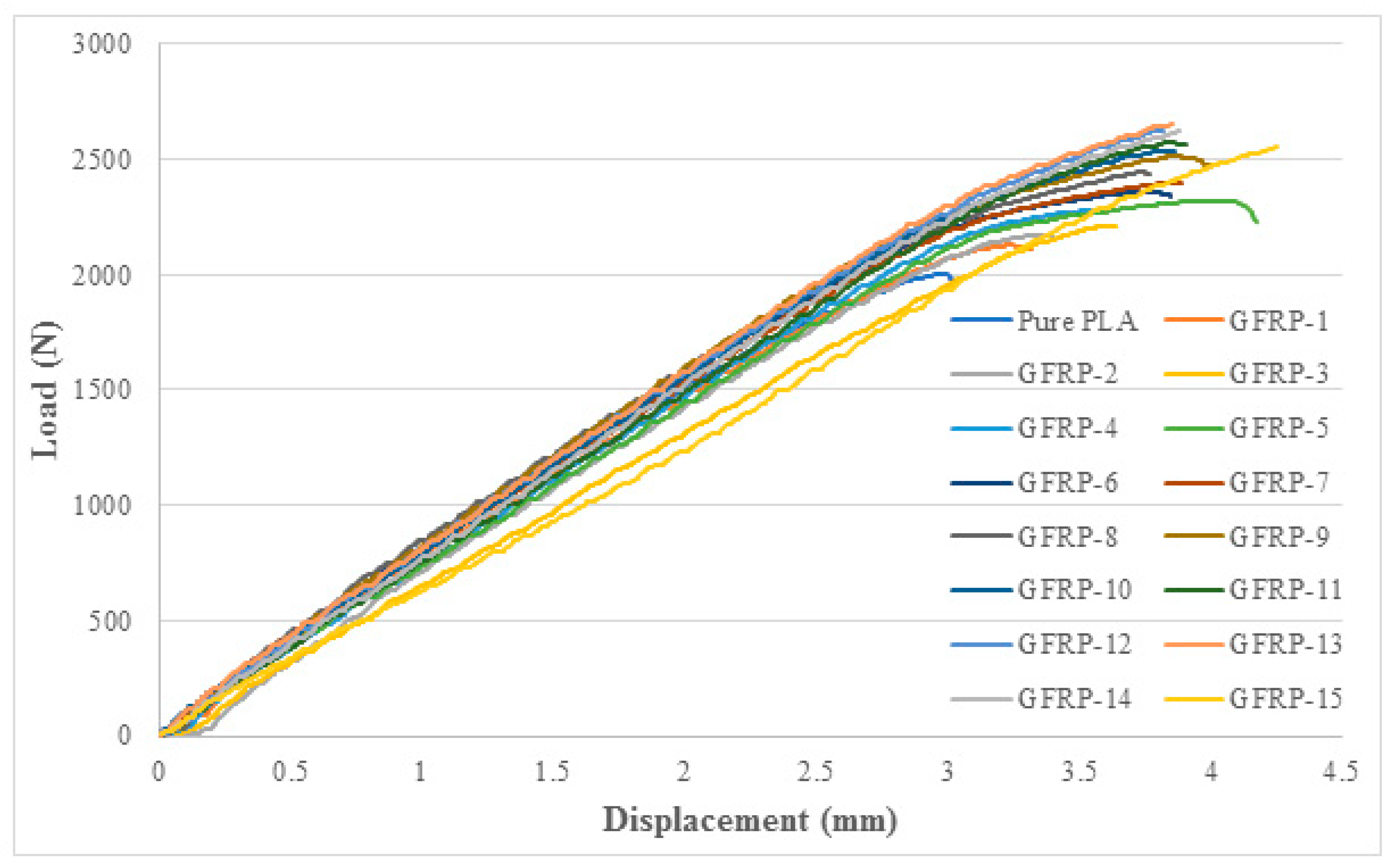
4.1. Effect of Glass Fiber Layers on Tensile Properties of the GFRP Composites

Force vs displacement curves for the pure PLA and GFRP composites are shown in Figure 7. The curve was selected from the results of three specimens, depending on the maximum value. It is obvious that the addition of glass fiber layers has increased the maximum load value that the product can sustain. The addition of one glass fiber layer (GFRP-1) has shown an increase of 6% compared to pure PLA. This value rose to 8% and 10% for composites with two (GFRP-2) and three (GFRP-3) glass fiber layers respectively. This linear increase in maximum load values is consistent with our previous work done with ABS plastic [18]. There has been no difference in the ductility of the products upon the addition of glass fiber layers as evident from the fracture modes shown in Figure 8. This means that glass fiber does not affect the brittle nature of the pure PLA plastic and this is carried over to the GFRP composites as well. All the specimens fractured without necking demonstrating a brittle failure.
It is evident in Figure 7 that the maximum load value is obtained for GFRP-13 (at 2656 N) and this is an increase of 32.5% compared to pure PLA (at 2005 N). After the addition of 13 layers, the maximum load value started to go down. At layer 14, the load value dropped to 2620 N (30.7% increase compared to pure PLA but a reduction of 1.8% compared to GFRP-13) with subsequent decrease on the addition of layer 15 to 2552 N (27.3% increase compared to pure PLA but a reduction of 5.2% compared to GFRP-13). This behavior is shown in Figure 9 where only the specimens with the largest fracture load values (out of three for each configuration) have been plotted as a percentage difference compared to pure PLA. The figure clearly shows an upward trend until layer 13 and then a decrease from this point onwards. This indicate that there is an optimal number of layers that can be added to the dog-bone specimen and it has been identified as 13 layers. This phenomenon has also been observed by other researchers with PLA based composites using FDM [10,11,12,13]. Anything more than 13 layers (of 0.03 mm thickness) will result in deterioration of tensile properties.
A graph with the average load values +/− standard deviations as error bars for the tensile tested GFRP composites and pure PLA specimens is shown in Figure 10. Such a graph highlights the variability and uncertainty in measured values. Since the programming of the 3D printer has not been adjusted to accommodate the addition of the glass fiber layers, the resulting GFRP composites should have a thickness value greater than 4.00 mm ± 0.2 mm. This effect has been analysed in the next section.

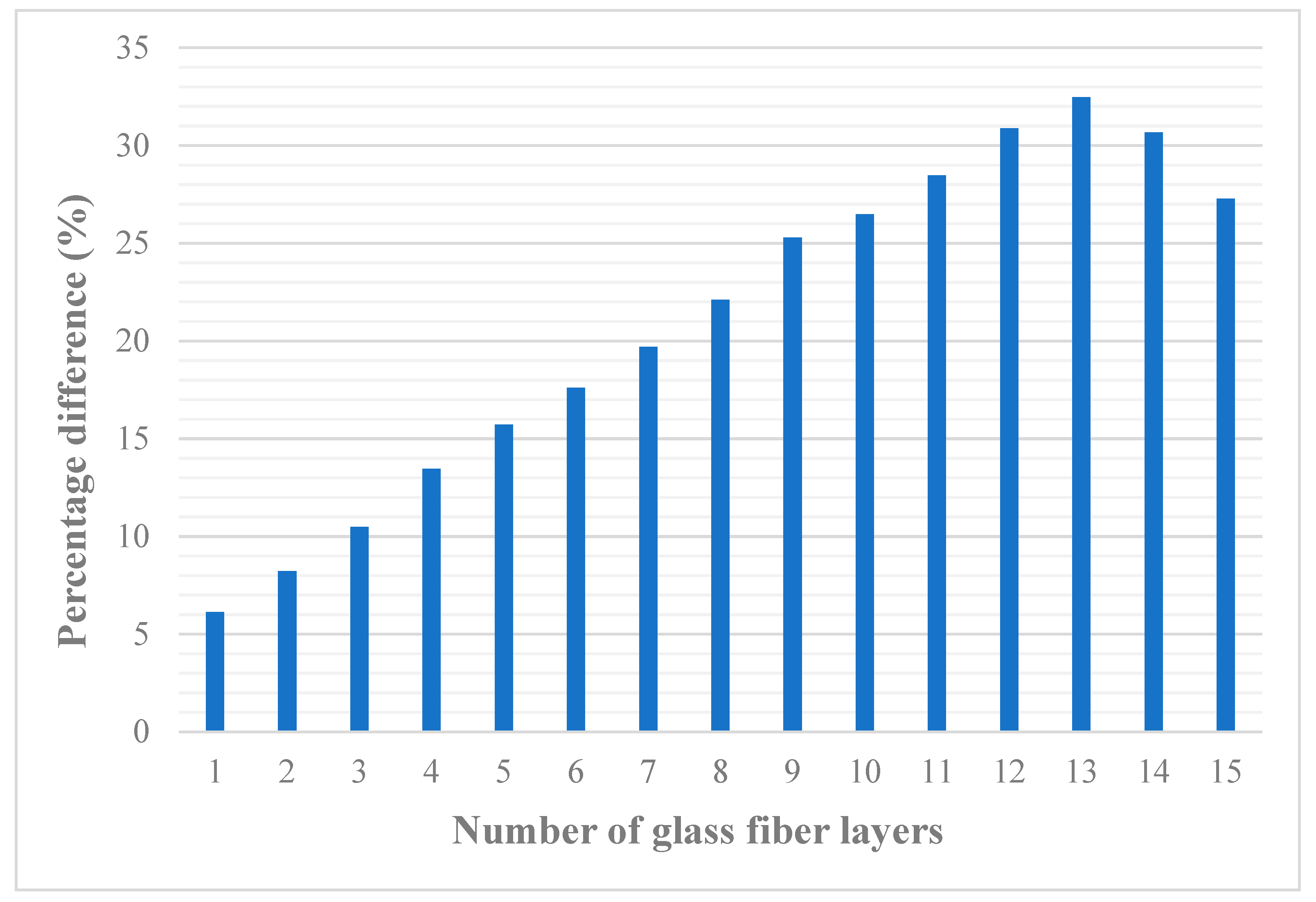
Effect of Glass Fiber Layers on Thickness of the GFRP Composites

FDM-printed parts are anisotropic in nature due to the way in which the layers are built [22]. They are also prone to warping [23]. This effect was also present during the manufacture of the GFRP composites. A Vernier caliper was used to measure the thickness of the dog-bone specimens at three sites i.e., two from the sides and one from the middle. The average value of these measurements was recorded. Figure 11 shows the comparison between the measured values and theoretical values based on the dimensions of the product. This comparison shows that the thickness of the GFRP composites did not increase based on the theoretical values. At certain instances, there is very little increase in thickness with the addition of another glass fiber layer. This shows that the semi-molten PLA material extruded from the nozzle of the 3D printer is not always depositing the 0.2 mm thick layer. As the 0.2 mm thick PLA layer comes into contact with the 0.03 mm glass fiber layer on the print bed, it encapsulates the glass fiber layer and thus the total thickness does not add up (0.2 mm + 0.03 mm = 0.23 mm). The dimensional inaccuracy can be attributed to several factors. Firstly, the accuracy (±0.2 mm) of the Anet A8 3D printer and the prevalence of structural defects (porosity) properties in the FDM process [24] play a part. Secondly, the programming was not adjusted to accommodate the additional 0.03 mm thick glass fiber layers. Third reason is the glass fiber layer itself as it is extremely thin with little to no air gaps. This help the layers to get trapped in the semi-molten PLA without any adhesive or glue. It is to be noted that the focus here was on analysing the effect of adhesion and not dimensional accuracy. This is a future research area that will include modifications to the dog-bone’s g-code to accommodate the glass fiber layers to ensure dimensional accuracy.
It is also important to highlight that the manufacture of GFRP products with increasing layers of glass fibers became exceedingly difficult after GFRP-9 as the clearance between the extruder nozzle and the print bed became smaller and smaller. The aim of the work is to identify the maximum number of layers that can be added before the tensile strength start to deteriorate. To achieve this in a consistent manner and keeping in mind the issue with the loss of clearance at GFRP-9, the print bed was moved downwards in the z-direction. Six turns of the screws underneath the print bed lowered it by 0.2 mm. This was easy to do as the experiment is already making use of the ‘Pause at height’ command that gives ample time to turn the four screws uniformly. This practice provided enough clearance between the nozzle and the part being manufactured to finish without issues.
As expected, the maximum thickness was observed for GFRP-15 (composite with 15 glass fiber layers) with 4.42 mm compared to the theoretical 4.45 mm. The thickness for the GFRP-13 composite that showed the maximum load value during tensile test (Section 4.1) is 4.37 mm compared to the theoretical value of 4.39 mm. It is crucial to analyse the maximum thickness value and its overall effect. A PLA specimen of (say) 4.5 mm thickness will show a higher load value compared to a specimen of 4 mm thickness. This is the case when the same material is being extruded out and adhered using FDM. In this work, there are glass fiber layers present that have shown to enhance the maximum load values. Another tensile test was performed based on the maximum theoretical thickness of 4.5 mm (rounded from 4.45 mm) and the results are shown in Figure 12. It is clear that the 4.5 mm thick specimen has a higher load value (2105 N) compared to the 4.1 mm (2005 N) thick pure PLA specimen. However, this value is still lower than GFRP-1 (2127.5 N). This shows that the increase in thickness with the addition of glass fiber layers does not adversely affect the tensile properties. This is a clear example of how HFDM can be used to manufacture products with tailored properties as increase in the number of glass fiber layers help in increasing the tensile strength of the GFRP composites.

4.2. Results from Microstructural Analysis

It is evident from the experimental results shown in Section 4.1 that the maximum load values were obtained for GFRP-13 and from this point onwards, the tensile strength started to deteriorate. This is because that maximum fiber content has been reached and any addition would result in degradation of properties. In addition to the optimisation of 3D printing parameters, there are several other material related factors that play a role in ensuring that high strength products are manufactured. They include efficiency of the interface stress transfer which represents the adhesion of the internal faces between glass fibers and PLA, fiber aspect ratio, fiber orientation, fiber volume fraction in the composite and the degree of crystallinity of the PLA [25]. To investigate these factors, the fracture interfaces of PLA and GFRP composites were observed by JCM-5000 NeoScope™ SEM as shown in Figure 13. First and foremost, all the tested specimens exhibited a brittle failure i.e., without showing any necking or plastic deformation before fracture. PLA is a brittle material and the resulting GFRP composites are also brittle in nature. FDM is a process of adding layers of extruded materials together and the development of porosity (or voids/micro voids/air gaps) is a common phenomenon [26]. These voids have been highlighted in Figure 13. Voids are empty areas between layers where there is no connection and a higher percentage of voids could lead to significant degradation of mechanical properties [27]. GFRP-1 shown in Figure 13b exhibit a neatly packed single layer of glass fiber to resist the tensile force with the brittle PLA and voids highlighted in its background. The voids of the glass fiber layers increase as can be seen in Figure 13c, d for GFRP-6 and GFRP-7 respectively. GFRP-13 shows the maximum load value but also shows several voids in Figure 13e. However, this phenomenon drastically increased for GFRP-14 in Figure 13f as the maximum load value start going down from this product onwards. The composites with 14 and 15 layers of glass fibers undergo both interlayer (decohesion of adjacent layers of FDM part) and intraleyer (decohesion between adjacent raster roads) fracture due to the high fiber volume. This is a commonly observed phenomenon with traditional FDM-printed parts [28] and when layers of glass fibers are added then the effect is enhanced even further resulting in extreme deterioration of tensile properties.
A closer look at the single layered GFRP composite (GFRP-1) in Figure 14 shows the interaction of PLA layers with the glass fibers. It is clear that the fibers are trapped between the PLA layers that is useful because the fiber matrix takes a high portion of the applied tensile load resulting in enhanced strength compared to pure PLA. This entrapment is required to ensure that the no additional treatment is needed to ensure cohesion and bonding between PLA and glass fibers. In some cases, alkali treatment for the fibers has been used to enhance the bonding capability [29]. In this case, however, the glass fibers were added without any surface treatment.

4.3. Results from Ultrasonic Testing

This test has been done to further evidence the effectiveness of the HFDM process and to aid the tensile test results so that destructive testing might not be needed. This NDT method can potentially help to assess the bonding quality of the GFRP composites. The test was conducted with all the specimens and three measurements were taken based on the description given in Section 3.3. The time taken by the high frequency acoustic sound waves to travel from one transducer through the test piece and to the second transducer is measured and the results are shown in Figure 15.
To establish base levels of sound travel through pure PLA, two specimens were used i.e., 4.1 mm and 4.5 mm. The times taken for sound waves to travel through the specimens were very similar. It took 2.0 μs, 2.1 μs and 2.0 μs for sound waves to travel through the 4.1 mm thick specimen. On the other hand, it took 2.1 μs, 2.1 μs and 2.2 μs for sound waves to travel through the 4.5 mm specimen. This shows that both the specimens were closely packed and the sound waves travelled quickly through the interconnected solid layers. The reason there are sometimes two values (as seen for pure PLA, GFRP-4, GFRP-5, GFRP-6, GFRP-7, GFRP-8, GFRP-10, GFRP-11, GFRP-14, GFRP-15) is because two measured values were the same. This shows uniformity of the GFRP composites and consistency of measurements. A trend similar to the one achieved for tensile testing (Figure 9) is observed showing that ultrasonic testing is an effective tool in assessing the bonding quality for the GFRP composites made by HFDM.
Typically for a thicker product (like 4.5 mm), the sound waves should take a longer time to travel from one end to the other because there are more hurdles in the way. However, the average travel times for 4.1 mm and 4.5 mm thick pure PLA specimens are 2.0 μs and 2.1 μs respectively. Since the difference is small, these specimens can be sued as reference points. As the number of glass fiber layers increased for the GFRP composites, the time taken to travel through them also increased up to layer 13. After that, it took less time to travel through composites with layers 14 and 15. This is due to the increase in porosity and voids in the GFRP composites. As mentioned earlier, porosity is a big issue for FDM-printed parts and the inclusion of glass fibers enhance this effect further. The voids are generally random in a FDM-printed part so that when stress is applied, the crack faces a higher resistance where there are no voids and no resistance at all if it meet a void. The voids/porosity can be controlled by changing the extruder and print bed temperature [30]. Furthermore, it has been proven by our results and work done by other researchers [31,32] that products with the lowest porosity result in the highest mechanical properties. As more and more layers were added to the PLA specimen, the voids increased. More layers mean more voids as shown in Section 4.2. This increases the statistical probability of the voids lining-up, thus reducing their randomness. This will lead to fracture of the GFRP at a lower load value as has been observed for GFRP-14 and GFRP-15. This alignment of voids also resulted in the sound waves travelling faster as the randomness had decreased, and the sound waves had a much clearer path to travel as now they face more solid layers than voids. Sound waves travel faster through solids than air because solid particles are more closely packed. This decrease in randomness of voids and more solid interaction contribute to the faster travel of sound waves through GFRP composites with more than 13 fiber layers.

5. Conclusions

In this study, commonly available PLA material was reinforced with 0.03 mm thick glass fiber layers to manufacture GFRP composites using HFDM. Experimental investigation was conducted to assess whether adding more glass fiber layers could yield higher tensile strength using standardised tensile testing. Fracture interfaces of pure PLA and GFRP composites were analysed after tensile testing using SEM micrographs. The products were also subjected to ultrasonic testing to assess whether this NDT method is suitable to use for products made by HFDM. The following conclusions were drawn from this study:
(1)
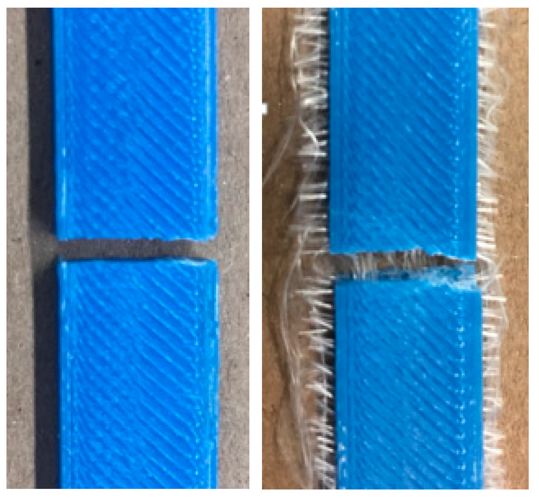
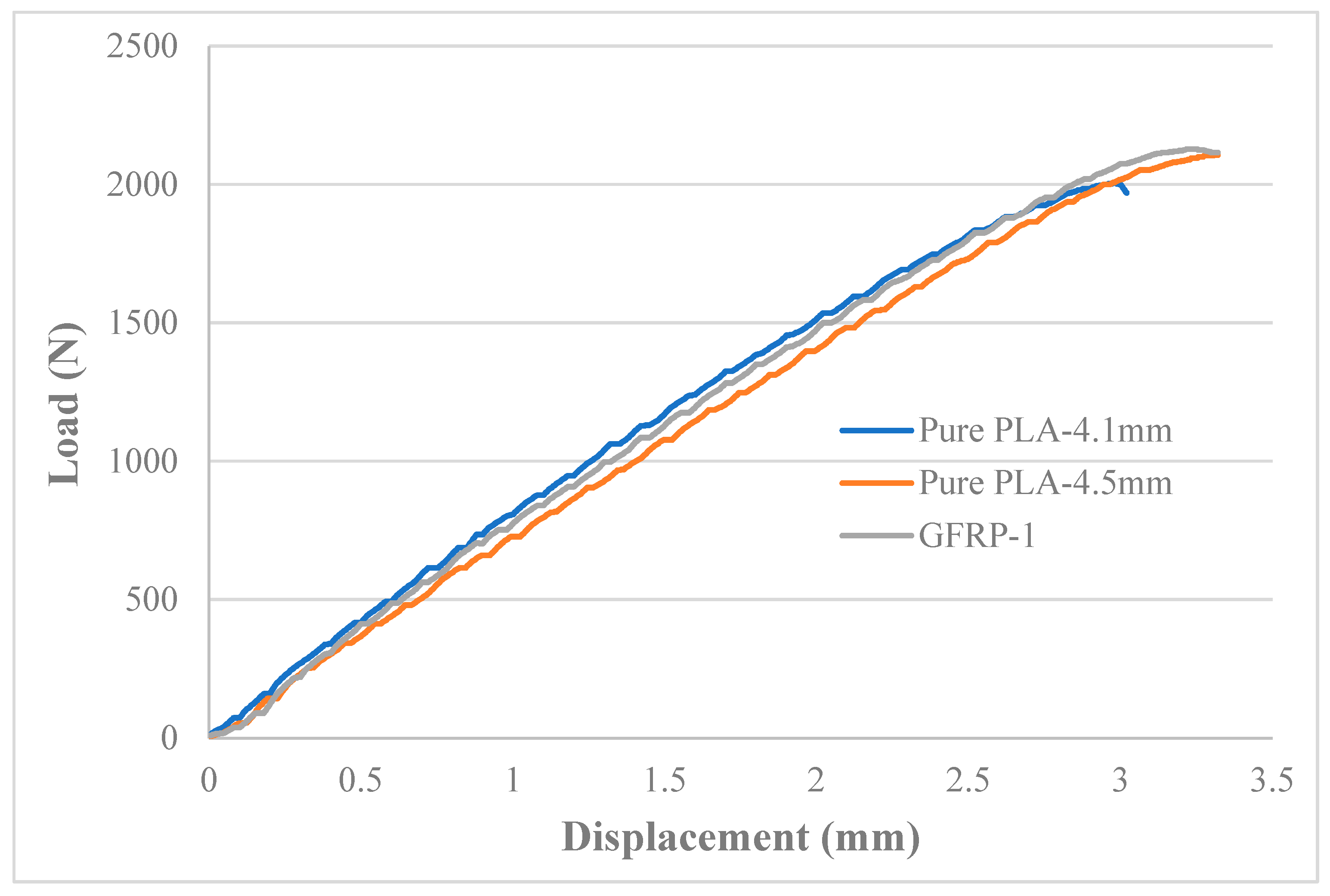
Strategic addition of 0.03 mm thick glass fibers can increase the tensile strength of the PLA products. The GFRP composites are also characterised by a brittle failure, same as the PLA material.
(2)
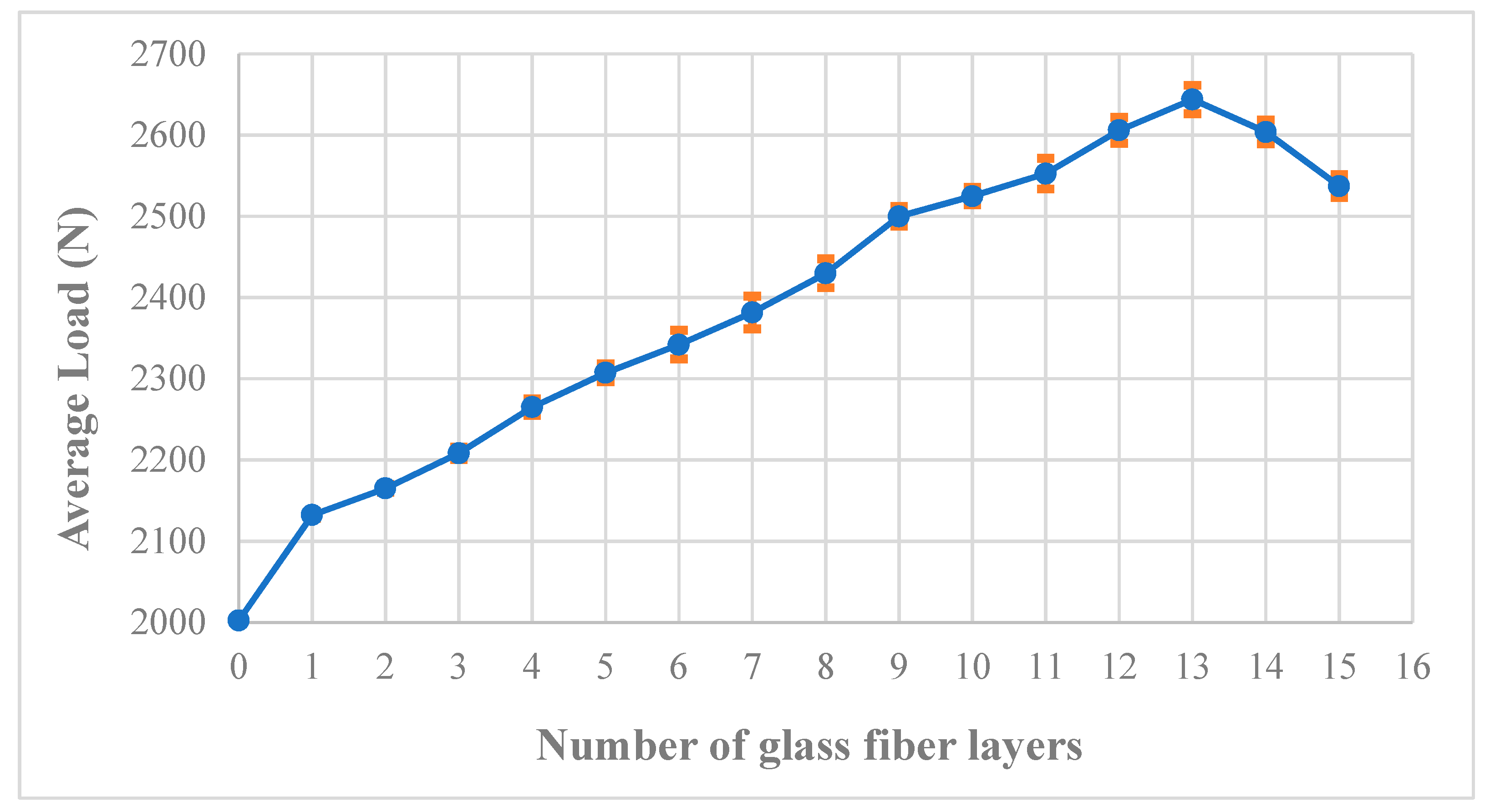
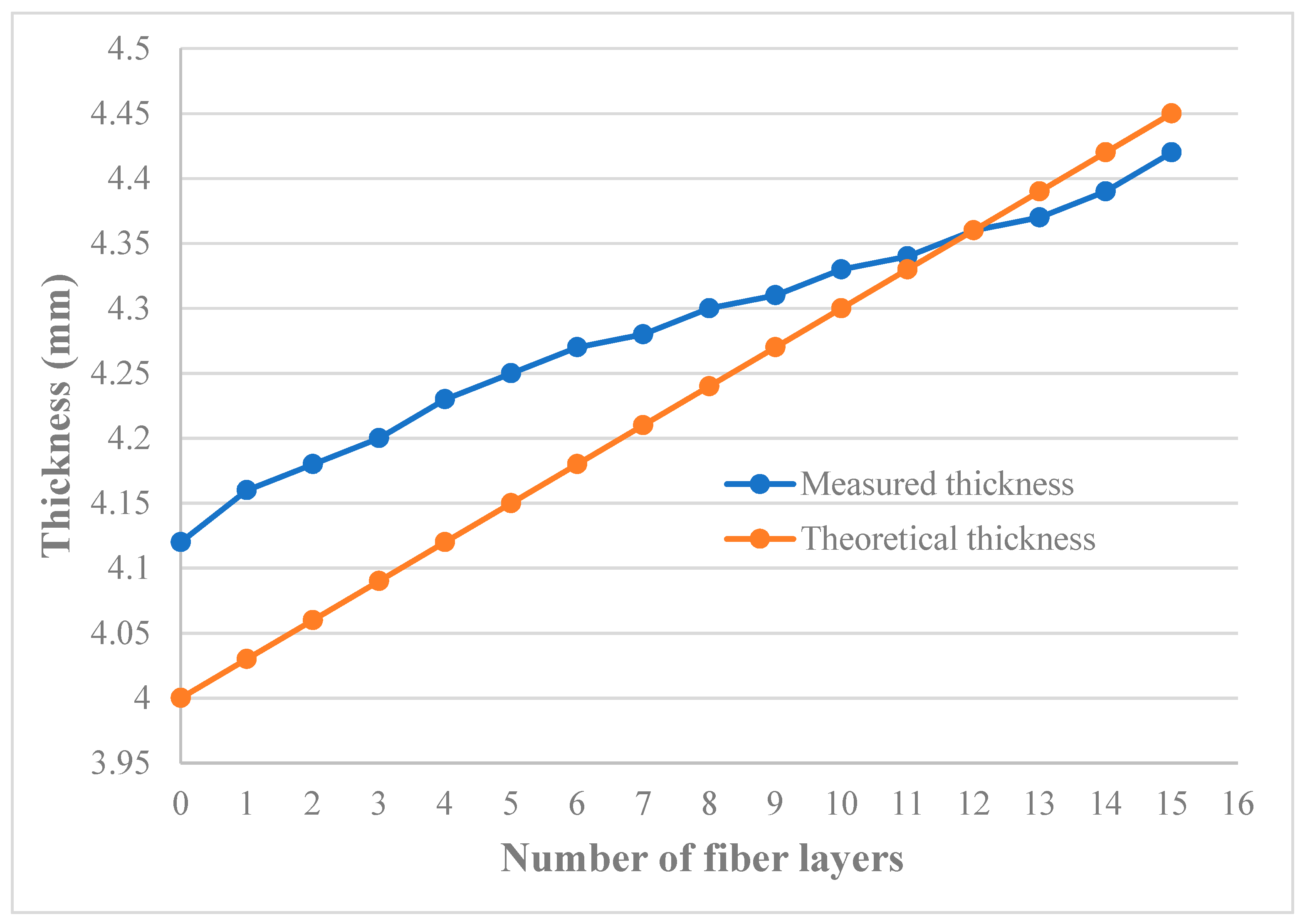
More glass fiber layers mean more tensile strength. However, their addition causes the thickness of the products to increase as well. The addition of 13 layers resulted in an increase of 32.5% in tensile strength compared to pure PLA. However, the addition of more layers led to deterioration of properties highlighting the optimal fiber content in the product.
(3)
Controlling the tensile properties for the manufacture of bespoke and customised GFRP products is possible. However, careful consideration should be given to the strength required and the increase in thickness.
(4)
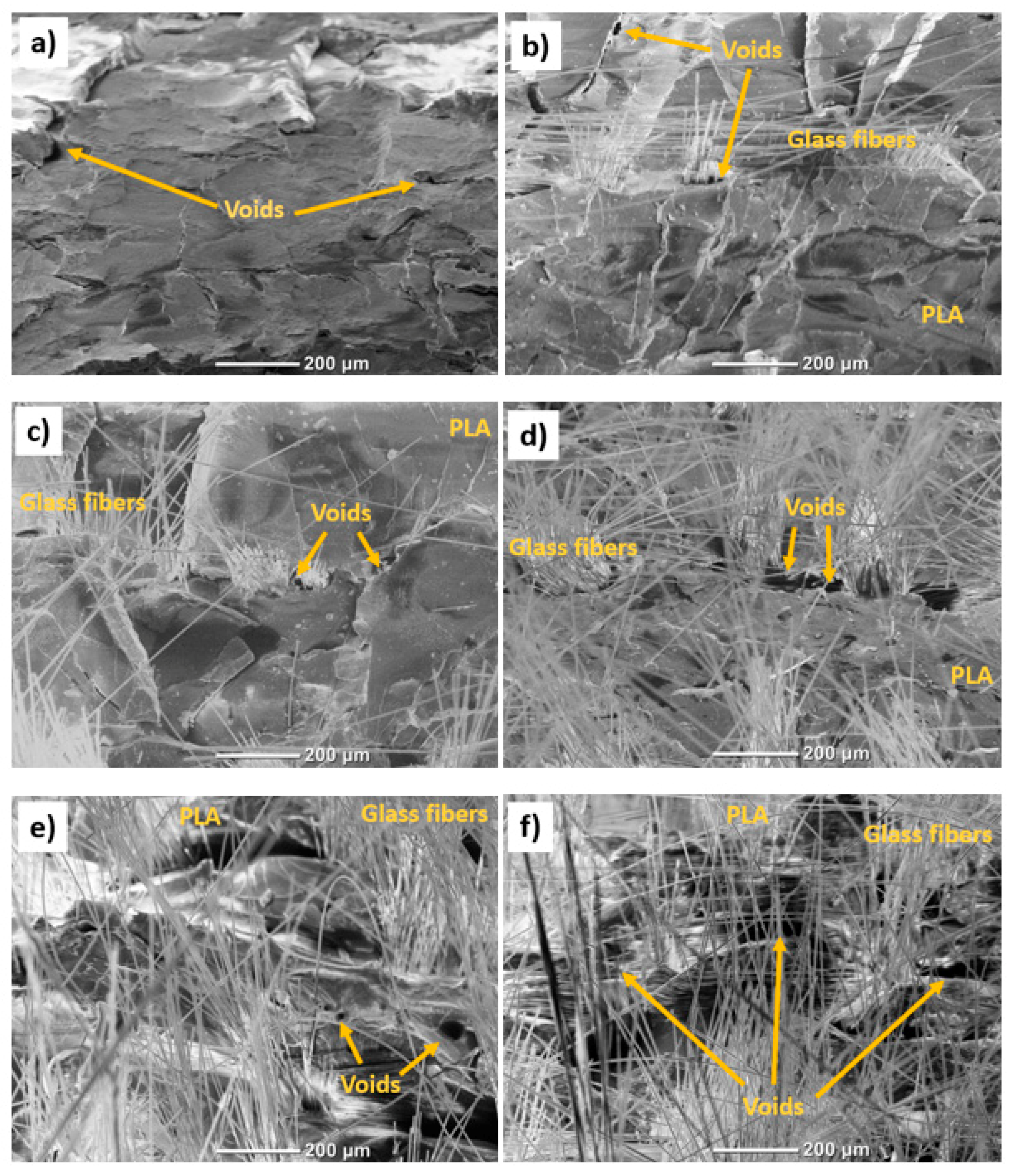
The presence of voids is common in FDM-printed parts and this phenomenon increased with the increase in the number of fiber layers. Until layer 13, the voids/porosity did not affect the upward trend of tensile strength. However, layers 14 and 15 showed substantially large voids resulting in lower mean values for maximum loads. SEM micrographs showed the presence of voids and highlighted their size.
(5)
Ultrasonic testing was used to assess the bond quality. It showed a similar trend as the tensile testing with the peak at 13 layers and downward trend onwards. This shows that ultrasonic testing can be sued in the future to assess the bond integrity of GFRP composites made by the process of HFDM.

Author Contributions

J.B. conceptualised the idea, designed the methodology, undertook data curation, investigation and formal analysis in addition to project administration and manuscript writing; Y.H. undertook data curation, investigation and wrote the original draft; V.M. undertook data curation and formal analysis; S.S.-E. acquired resources and worked on the original draft; H.S. reviewed and edited the final manuscript.

Funding

This research did not receive any external funding.

Conflicts of Interest

The authors declare no conflict of interest.

References

  1. Dudek, P.F. FDM 3D printing technology in manufacturing composite elements. Arch. Metall. Mater. 2013, 58, 1415–1418. [Google Scholar] [CrossRef]
  2. Justo, J.; Távara, L.; García-Guzmán, L.; París, F. Characterization of 3D printed long fibre reinforced composites. Compos. Struct. 2018, 185, 537–548. [Google Scholar] [CrossRef]
  3. Butt, J.; Mebrahtu, H.; Shirvani, H. Metal Rapid Prototyping Technologies. In Advances in Engineering Research; Petrova, V.M., Ed.; Nova Science Publishers, Inc.: New York, NY, USA, 2017; Chapter 2; Volume 14, pp. 13–52. [Google Scholar]
  4. Butt, J.; Shirvani, H. Additive, Subtractive, and Hybrid Manufacturing Processes. In Advances in Manufacturing and Processing of Materials and Structures; CRC Press: Boca Raton, FL, USA, 2018; pp. 187–218. [Google Scholar]
  5. Osman, M.A.; Atia, M.R. Investigation of ABS-rice straw composite feedstock filament for FDM. Rapid Prototyp. J. 2018, 24, 1067–1075. [Google Scholar] [CrossRef]
  6. Ivanov, E.; Kotsilkova, R.; Xia, H.; Chen, Y.; Donato, R.K.; Donato, K.; Godoy, A.P.; Di Maio, R.; Silvestre, C.; Cimmino, S.; et al. PLA/graphene/MWCNT composites with improved electrical and thermal properties suitable for FDM 3D printing applications. Appl. Sci. 2019, 9, 1209. [Google Scholar] [CrossRef]
  7. Butt, J.; Mebrahtu, H.; Shirvani, H. Production of Multiple Material Parts Using a Desktop 3D Printer. In Advances in Manufacturing Technology XXXI: Proceedings of the 15th International Conference on Manufacturing Research, Incorporating the 32nd National Conference on Manufacturing Research, University of Greenwich, London, UK, 5–7 September 2017; IOS Press: Amsterdam, The Netherlands, 2017; Volume 6, pp. 148–153. [Google Scholar] [CrossRef]
  8. Butt, J.; Onimowo, D.A.; Gohrabian, M.; Sharma, T.; Shirvani, H. A desktop 3D printer with dual extruders to produce customised electronic circuitry. Front. Mech. Eng. 2018, 13, 528–534. [Google Scholar] [CrossRef]
  9. Butt, J. A Novel Additive Manufacturing Process for the Production of Metal Parts. Ph.D. Thesis, Anglia Ruskin University, Cambridge, UK, 2016. [Google Scholar]
  10. Ning, F.; Cong, W.; Qiu, J.; Wei, J.; Wang, S. Additive manufacturing of carbon fiber reinforced thermoplastic composites using fused deposition modeling. Compos. Part B Eng. 2015, 80, 369–378. [Google Scholar] [CrossRef]
  11. Liu, Z.; Lei, Q.; Xing, S. Mechanical characteristics of wood, ceramic, metal and carbon fiber-based PLA composites fabricated by FDM. J. Mater. Res. Technol. 2019, 8, 3741–3751. [Google Scholar] [CrossRef]
  12. Coppola, B.; Garofalo, E.; Di Maio, L.; Scarfato, P.; Incarnato, L. Investigation on the use of PLA/hemp composites for the fused deposition modelling (FDM) 3D printing. In Proceedings of the AIP Conference Proceedings, Bali, Indonesia, 11 July 2018; Volume 1981, p. 020086. [Google Scholar]
  13. Tao, Y.; Wang, H.; Li, Z.; Li, P.; Shi, S.Q. Development and application of wood flour-filled polylactic acid composite filament for 3D printing. Materials 2017, 10, 339. [Google Scholar] [CrossRef] [PubMed]
  14. Patanwala, H.S.; Hong, D.; Vora, S.R.; Bognet, B.; Ma, A.W. The microstructure and mechanical properties of 3D printed carbon nanotube-polylactic acid composites. Polym. Compos. 2018, 39, E1060–E1071. [Google Scholar] [CrossRef]
  15. Gkartzou, E.; Koumoulos, E.P.; Charitidis, C.A. Production and 3D printing processing of bio-based thermoplastic filament. Manuf. Rev. 2017, 4, 1. [Google Scholar] [CrossRef]
  16. Sanatgar, R.H.; Campagne, C.; Nierstrasz, V. Investigation of the adhesion properties of direct 3D printing of polymers and nanocomposites on textiles: Effect of FDM printing process parameters. Appl. Surf. Sci. 2017, 403, 551–563. [Google Scholar] [CrossRef]
  17. Eutionnat-Diffo, P.A.; Chen, Y.; Guan, J.; Cayla, A.; Campagne, C.; Zeng, X.; Nierstrasz, V. Stress, strain and deformation of poly-lactic acid filament deposited onto polyethylene terephthalate woven fabric through 3D printing process. Sci. Rep. 2019, 9, 1–18. [Google Scholar] [CrossRef] [PubMed]
  18. Butt, J.; Shirvani, H. Experimental analysis of metal/plastic composites made by a new hybrid method. Addit. Manuf. 2018, 22, 216–222. [Google Scholar] [CrossRef]
  19. Keleş, Ö.; Blevins, C.W.; Bowman, K.J. Effect of build orientation on the mechanical reliability of 3D printed ABS. Rapid Prototyp. J. 2017, 23, 320–328. [Google Scholar] [CrossRef]
  20. Garg, A.; Bhattacharya, A.; Batish, A. Failure investigation of fused deposition modelling parts fabricated at different raster angles under tensile and flexural loading. Proc. Inst. Mech. Eng. Part B J. Eng. Manuf. 2017, 231, 2031–2039. [Google Scholar] [CrossRef]
  21. BS EN ISO 527-2:2012. Plastics—Determination of Tensile Properties–Part 2: Test Conditions for Moulding and Extrusion Plastics; British, European and International Standard: London, UK, 2012. [Google Scholar]
  22. Popescu, D.; Zapciu, A.; Amza, C.; Baciu, F.; Marinescu, R. FDM process parameters influence over the mechanical properties of polymer specimens: A review. Polym. Test. 2018, 69, 157–166. [Google Scholar] [CrossRef]
  23. Xinhua, L.; Shengpeng, L.; Zhou, L.; Xianhua, Z.; Xiaohu, C.; Zhongbin, W. An investigation on distortion of PLA thin-plate part in the FDM process. Int. J. Adv. Manuf. Technol. 2015, 79, 1117–1126. [Google Scholar] [CrossRef]
  24. Gordeev, E.G.; Galushko, A.S.; Ananikov, V.P. Improvement of quality of 3D printed objects by elimination of microscopic structural defects in fused deposition modeling. PLoS ONE 2018, 13, e0198370. [Google Scholar] [CrossRef]
  25. Yang, Z.; Feng, X.; Bi, Y.; Zhou, Z.; Yue, J.; Xu, M. Bleached extruder chemi-mechanical pulp fiber-PLA composites: Comparison of mechanical, thermal, and rheological properties with those of wood flour-PLA bio-composites. J. Appl. Polym. Sci. 2016, 133. [Google Scholar] [CrossRef]
  26. Liao, Y.; Liu, C.; Coppola, B.; Barra, G.; Di Maio, L.; Incarnato, L.; Lafdi, K. Effect of Porosity and Crystallinity on 3D Printed PLA Properties. Polymers 2019, 11, 1487. [Google Scholar] [CrossRef]
  27. Mehdikhani, M.; Gorbatikh, L.; Verpoest, I.; Lomov, S.V. Voids in fiber-reinforced polymer composites: A review on their formation, characteristics, and effects on mechanical performance. J. Compos. Mater. 2019, 53, 1579–1669. [Google Scholar] [CrossRef]
  28. Young, D.; Wetmore, N.; Czabaj, M. Interlayer fracture toughness of additively manufactured unreinforced and carbon-fiber-reinforced acrylonitrile butadiene styrene. Addit. Manuf. 2018, 22, 508–515. [Google Scholar] [CrossRef]
  29. Hu, R.; Lim, J.K. Fabrication and mechanical properties of completely biodegradable hemp fiber reinforced polylactic acid composites. J. Compos. Mater. 2007, 41, 1655–1669. [Google Scholar] [CrossRef]
  30. Spoerk, M.; Gonzalez-Gutierrez, J.; Sapkota, J.; Schuschnigg, S.; Holzer, C. Effect of the printing bed temperature on the adhesion of parts produced by fused filament fabrication. Plast. Rubber Compos. 2018, 47, 17–24. [Google Scholar] [CrossRef]
  31. Chin Ang, K.; Fai Leong, K.; Kai Chua, C.; Chandrasekaran, M. Investigation of the mechanical properties and porosity relationships in fused deposition modelling-fabricated porous structures. Rapid Prototyp. J. 2006, 12, 100–105. [Google Scholar] [CrossRef]
  32. Cuan-Urquizo, E.; Barocio, E.; Tejada-Ortigoza, V.; Pipes, R.B.; Rodriguez, C.A.; Roman-Flores, A. Characterization of the mechanical properties of FFF structures and materials: A review on the experimental, computational and theoretical approaches. Materials 2019, 12, 895. [Google Scholar] [CrossRef] [Green Version]
Figure 1. Anet A8 3D printer in operation.
Jmmp 03 00096 g001
Figure 2. Manufacture of GFRP composites.
Jmmp 03 00096 g002
Figure 3. Glass fiber layer atop PLA specimen.
Jmmp 03 00096 g003
Figure 4. Dimensions of the tensile testing dog-bone specimen.
Jmmp 03 00096 g004
Figure 5. Calibration of the transducers before testing.
Jmmp 03 00096 g005
Figure 6. Placement of transducers for measurements.
Jmmp 03 00096 g006
Figure 7. Tensile test results for pure PLA and GFRP composites.
Jmmp 03 00096 g007
Figure 8. Fracture mode of pure PLA (left) and GFRP-1 composite (right).
Jmmp 03 00096 g008
Figure 9. Percentage difference of maximum load values between GFRP composites and pure PLA.
Jmmp 03 00096 g009
Figure 10. Graph showing average load values +/− standard deviations as error bars for the tensile tested GFRP composites and pure PLA specimens.
Jmmp 03 00096 g010
Figure 11. Comparison of measured and theoretical thickness values.
Jmmp 03 00096 g011
Figure 12. Tensile test results for pure PLA and GFRP-1 composite.
Jmmp 03 00096 g012
Figure 13. SEM fracture interfaces at x100; (a) Pure PLA; (b) GFRP-1; (c) GFRP-6; (d) GFRP-7; (e) GFRP-13; (f) GFRP-14.
Jmmp 03 00096 g013
Figure 14. SEM images of GFRP-1 at ×200 (left) and ×900 (right).
Jmmp 03 00096 g014
Figure 15. Results from ultrasonic testing.
Jmmp 03 00096 g015

