Abstract
Demineralized bone matrix (DBM) is an excellent bone scaffold material, but is available in only limited sizes. An additive manufacturing (AM) method that retains these properties while enabling customized geometry fabrication would provide bone scaffolds for a larger range of geometries while maintaining the benefits of DBM. This work examines laser sintering (LS) of a blend of demineralized bone matrix (DBM) and polycaprolactone (PCL) using a CO2 laser beam. A comprehensive experimental study was carried out to find the conditions that form defect-free layers while still retaining the favorable biological features of DBM. The results identify a process setting window over which LS can be utilized to constructing complex patient-specific scaffolds. With the identified setting, first, the DBM/PCL blend was fused in the LS machine. Parts were then were further strengthened through a post-processing heat treatment. The shrinkage level, skeletal density, mechanical testing, and porosimetry of the resultant samples were compared to traditional machined DBM blocks. The maximum tensile strength of the samples and post-processing shrinkage depends on heat treatment duration. The tensile strength measurements demonstrate that the post-processing conditions can be tuned to achieve the tensile strength of the demineralized bone strips. Evaluation of the dimensional change suggests that the shrinkage along the laser paths is ~0.3% while thickness shrinks the most (up to ~20%). The porosimetry and density studies showed that the final part achieved over 40% porosity with a density comparable to blocks of DBM.
1. Introduction
Some treatments of damaged tissue require a scaffold that can mimic aspects of the missing tissue in an in vivo environment to support healing. Materials taken from the human body have superior biocompatibility compared to synthetic material [1,2]. Furthermore, they integrate into the body—eliminating the need for a second removal surgery [3]. Therefore, the donated tissues taken from a cadaver (known as allografts) have been a preferred material for regenerating injured tissues such as bone [2]. However, allografts are available in limited geometries. A method of fabricating allograft structures of arbitrary geometry from donated tissues while retaining favorable features would allow the fabrication of customized geometry to meet patient requirements.
Additive manufacturing (AM) has the capability of fabricating arbitrary geometries, but typical AM materials have significant limitations as scaffolds [4]. An AM method that utilized donated tissue, while maintaining key biological functionality, could provide significantly improved treatments, but the process may alter the biological features of the material during fabrication. In this study, we investigated the adaptation of laser sintering (LS) to fuse a demineralized bone matrix (DBM)/polymer composite. Laser sintering (LS) is an AM technique that uses laser to selectively sinter the particles based on the 2D slices of a CAD model [5]. Additional 2D layers are processed sequentially to build up a 3D physical object.
Good mechanical properties, excellent accuracy, and high build rates have made LS valuable in the industry. Expanding the range of materials that can be sintered is key to further growth [6]. In this regard, one of the most promising directions is the development of composite material systems [7,8,9]. This is of particular value in biomaterials where mechanical properties, composition, and geometry have a strong impact on functionality [10]. The pores should have the characteristics to facilitate cell ingrowth in the actual body microenvironment. Work in this area was reviewed by Loh et al. [11].
Efforts to apply laser sintering for tissue engineering applications are actively being explored and diverse methods have been demonstrated to create porous scaffolds with an interconnected 3D flow channel network [11,12]. As an example, calcium phosphate was processed by an intermediate polymer which was thermally removed during post-processing [13]. Tan et al. [14] conducted a study on producing a biocomposite of polyetheretherketone (PEEK) and hydroxyapatite (HA). They found that increased bed temperature resolved a delamination problem and enhanced the layer integrity. The degree of interparticle boding could be controlled by adjusting LS process parameters.
LS fabrication with DBM particulates has not been reported previously. However, a composite of DBM and polycaprolactone (PCL) and the mixture has been fabricated by fused deposition modeling (FDM) [15] and large area projection sintering (LAPS) [16]. Hung et al. fabricated DBM/PCL scaffolds containing up to 70 wt % DBM using FDM [17]. The composite samples had greater cell proliferation compared to control samples of pure PCL. However, this approach embeds much of the DBM in PCL, reducing its biological impact and potentially altering its geometry. Alternatively, a mixture of DBM and PCL powders could be selectively fused using a lower PCL content to increase porosity and exposure of DBM surfaces to improve biological performance if the mechanical properties are sufficient. Previous research showed promising mechanical properties by using a projected image to fuse the DBM/PCL blend. However, the geometric accuracy was insufficient due to the poor absorption of the projected wavelength [1].
Although the advantages of using a CO2 laser to process DBM particles were described earlier, the focused beam could pose the risk of overheating this valuable graft donation. This paper investigates the feasibility of using a CO2 laser to process DBM/PCL composites to achieve basic mechanical functionality. The biological viability of the process is not assessed here. DBM particles impose a strict limitation on the process conditions due to their sensitivity to temperature. Processing conditions must be carefully controlled to melt the PCL while not overheating the DBM (Tmax ~70 °C). There are over 50 variables that play a role in laser-based additive manufacturing that fall under four major groups: (1) laser parameters and scan strategies; (2) powder properties; (3) spread layer quality; and (4) processing environment conditions [18,19,20]. This paper will focus on laser parameters and scanning strategies.
2. Experimental Methods and Materials
2.1. Materials and Layer Formation Study
Laser sintering requires a thermal bonding agent. Typically, all or part of the raw material melts and densifies under surface energy forces when heated by the laser. Since DBM does not melt on heating, a secondary thermal bonding agent must be added to the mixture. Potential biopolymers were screened and polycaprolactone (PCL) was selected as the matrix for the DBM powder due to its low melting point and biocompatibility. For this project, the PCL was purchased from Polysciences Inc. The as-received powder was sieved and the portion <300 μm was used in this research. The Discovery from TA instruments was utilized to take a differential scanning calorimeter (DSC) measurement of the PCL, which showed that this PCL has a melting point of Tm ~63 °C, below the processing limits of the DBM [21]. The molecular weight of the PCL was reported 50,000 g/mol and the shape of the PCL was irregular. An initial test was performed on pure PCL to make sure that the laser effectively interacts with PCL. Where the CO2 laser beam traces the surface, local bonds form between PCL particles, as seen in Figure 1. The PCL is a feasible bonding agent for the DBM/PCL mixture.
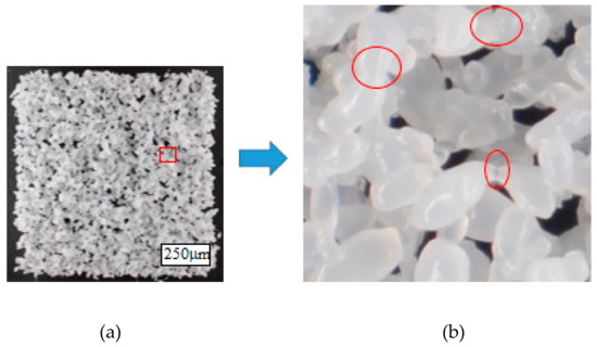
Figure 1.
A primitive layer of 1 cm scanned by the CO2 laser at p = 5.2 W, d = 0.1 mm, and V = 100 mm/s. (a) the clean definition of the edges; (b) the neck formation between the particles in a 50× magnified photograph.
Donated cadaveric bone was processed at LifeLink Tissue Bank, where a proprietary clinical cleaning process was used to remove the blood, lipids, viable cells, and microorganisms. The cortical bone was further processed by grinding to create a coarse powder. The resultant DBM powder was sieved and the granules smaller than 250 μm were utilized. The processing and mechanical properties are sensitive to the fraction of PCL and DBM used in the blend. Prior work showed that a 45 wt % DBM and 55 wt % PCL mixture results in good mechanical properties (comparable to pure DBM) while maximizing DBM content [1]. The same mixture was used in this study. Scanning was done with a Rabbit HX-SE-1290 system with a CO2 laser tube that operates at 80 watts nominal power. According to the laser apparatus specifications, the beam spot size in the focal distance of 51 mm is 0.2 mm. In order to minimize the local heating of the samples, relatively low laser power, and slow scan speeds were studied. Generally, at such low powers, laser power values may not be accurate, but the results of this study indicate key tradeoffs and reflect the potential for using a low-cost laser cutter for additive fabrication.
The interaction between the laser beam and the material system was studied by fabricating single layer primitives that were 1 cm × 1 cm with a range of speed, laser power, and line spacing. For consistency, throughout this research, all experiments were performed by a bidirectional raster pattern (see Figure 2) at room temperature (no bed preheat). The laser parameter setting started with a low laser power at which no bonding initiated. For each set of scanning conditions, the laser power was gradually raised until interparticle bonding emerged, marking the lower bound of processing power. This incrementing continued by 0.008 or 0.08 watts until the color change of DBM material occurred, identifying an upper bound of the processing power range.
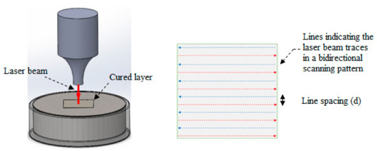
Figure 2.
The schematic of the bidirectional raster laser scanning.
This comprehensive study identified the parameter window over which the materials could be processed without visible damage. Successful processing required that the powder mixture fused together without curling out of plane. The layer cohesion must be at least sufficient to be handled without damage. It was observed that the layers have insufficient strength to survive handling directly after fusing. To enhance the cohesiveness of the layers, two different methods were examined. In the first approach, the line spacing was reduced to stitch the neighboring traces to each other more effectively, and in the second, the distance between the bed surface and the laser exit aperture was increased to enlarge the laser spot size, delivering energy to a larger area. The laser spot size estimation for the new laser-to-powder distance was performed by knowing the fact that, based on laser specifications and at 51 mm focal distance, the spot size was 0.2 mm. This spot size was found to be the same as the individual laser trace line widths on plywood at a speed of 150 mm/s and p = 5.36 W. With the same parameters, the spot size for 57 mm distance was estimated as 800 μm. For each case, the weight of the primitive layers was considered as an indicator of thickness and integrity of the layer.
Multilayer parts were fabricated by adding a layer spreading apparatus into the laser cutting system. A layering set-up was designed and built considering the space limitations inside the work envelope of the laser cutter (Figure 3). To form a layer, the powder supply piston raises the material; at the same time, the build piston goes down to accommodate one new layer. Then, the counter-rotating roller with a rotational speed of 120 rpm and 50 mm/s traverse speed recoats the material over the build platform, and retracts to its initial place. The laser scanning is manually triggered to fuse one 2D layer. By repeating this process and putting down successive layers, the 3D geometry was created.
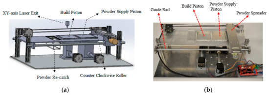
Figure 3.
(a) The schematic of the layering system designed to work in conjunction with a CO2 laser to fabricate the samples. (b) A photograph of the hardware. The supply piston starts in a low position and is filled with raw material. For each new layer, the supply piston raises and the build piston lowers. The roller is then moved over the bed to level the powder.
2.2. Sample Preparation
The spreading test results performed in our previous study [1] showed that the mixture of DBM <250 μm and PCL <300 μm powders can spread uniform layers of 500 μm thickness. Therefore, the layer thickness was set at 500 μm for fabricating test coupons. In this study, two types of samples were fabricated: tensile bars for dimensional change and tensile strength assessment, and 5 mm cubes for density and porosimetry analysis. All these samples, regardless of the geometry, were printed by laser power = 5.36 W, line spacing = 100 μm, and scan speed = 150 mm/s.
In total, 9 tensile bars composed of 45 wt % DBM-PCL with a 500 μm layer thickness were printed. The CAD dimensions of the gauge section were in accordance with ASTM D638-10 standard with a 13 mm width and 6 mm thickness. The overall length of the samples was 64 mm. The tensile bar samples were printed in the x–y plane with the long direction in the rolling direction. The as-printed tensile bars showed sufficient mechanical properties for handling but were weaker than pure DBM strips. Thus, isothermal heat treatments were carried out in a convection oven at 65 °C, which is slightly above the measured melting point of the PCL. Each set of three samples was considered as a group to undergo different heat treatment durations: 3 h, 5 h, and 7 h. Three DBM strips were machined to have a 13 mm gauge width to be consistent with the printed samples for strength comparison [1]. Figure 4 shows an example of composite tensile bars before and after 5 h heat treatment and the reference sample which was machined from DBM. The cube samples which were for density and porosimetry studies were heat-treated for 5 h.
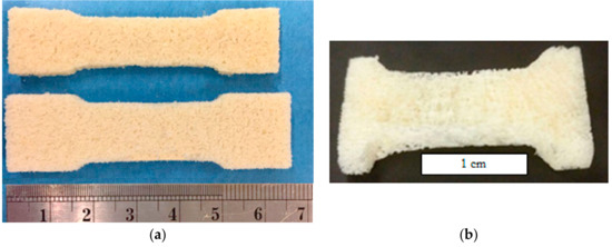
Figure 4.
Example of tensile bar built by laser sintering (LS) used in Ultimate Tensile Test (UTS) measurements. (a) The tensile bar built by Laser Sintering (LS). Bottom: green body; top: the sample cured at 65 °C for 5 hours. (b) The machined demineralized bone matrix (DBM) strip [1].
The 5 mm cubes were manufactured using two DBM weight fractions: 45 wt% DBM and 55 wt% DBM. This allows identifying the role of DBM content in density and porosity of the scaffold. The printed composite cubes heat-treated at 65 °C for 5 h in post-processing and to have a reference sample, the DBM strips were was cut into the same dimension for the density and pore characterization experiments. The skeletal density was measured by using two different techniques for comparison: the helium pycnometer (UltraPyc 1200e) and mercury intrusion porosimetry (MIP), model PoreMaster 60, both from Anton Paar. Besides density, the MIP technique is capable of analyzing porosity. The first set of measurements were taken by the helium pycnometer, then the same samples were utilized in the MIP instrument to minimize the error that would have been caused by using new samples. The mercury penetration porosimeter correlates the penetrated volume of mercury and the penetration pressure for each sample. The pressure increases from 3.5 Kpa to 4.1 × 10⁵ Kpa and the porosity is determined herewith.
3. Results and Discussion
In this section, we describe how the key process parameters impact the layer quality and DBM discoloration. The results include the first series of experiments that were conducted on the layer primitives to find the best combination of process settings to use for multi-layer parts. Tensile bars were fabricated to investigate heat treatment impact on dimensional deviation and mechanical strength. In addition to the tensile bars, 5 mm cubes were manufactured to study skeletal density and void volume fraction in the final parts.
3.1. Process Parameters Effect on DBM/PCL Primitive Layers
The layers are composed of the adjacent lines cured by the laser path. Initially, the stepover was set at 100 μm for which the lines laterally met each other and formed a layer. However, it was expected that reducing stepover distance by half should stitch the lines to each other more effectively, but Figure 5 shows that the variation of stepover changes the operation window significantly at the higher scan speeds. The processing window for the 100 μm line spacing expands for higher vector speeds. However, layers made with a line spacing of 50 μm show little change in the size of the processing window with scan speed in the ranges tested. Delivering excessive energy into the material may burn the DBM in the powder bed. This is more critical at the end of the laser vector where the beam turns back to trace a fresh line in which case the previously delivered energy has not sufficiently been dissipated and overheating is more likely to happen. Running the process with small line gaps would necessitate using a tightly controlled laser power with minimal fluctuation.
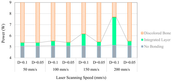
Figure 5.
The assessment of the line spacing (D) effect on the DBM/polycaprolactone (PCL) color change to the identify safe operational window for the combination of scan speed and power for single layer parts. The powder bed distance from the lens is 51 mm with the spot size of 200 μm.
The second parameter examined was the beam spot size. The spot sizes were increased from 200 μm to 800 μm by changing the laser-to-powder bed distance from 51 mm to 57 mm. The experiments were conducted for a combination of power and speeds (see Figure 6). The expanded beam spot delivers energy into a wider trace of material and keeps the PCL softened for a longer period of time yielding better cohesion in the layer. The attenuation of the energy intensity can be compensated by operating at a higher laser power. The feasible range of powers increased significantly, but the size of the print features is limited to beam size (800 μm).
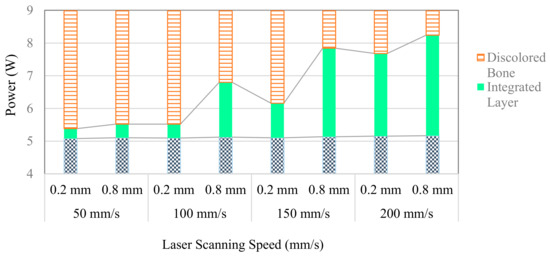
Figure 6.
The comparison of safe operational range to processing DBM/PCL for two laser spot sizes (0.2 mm, 0.8 mm) and a range of scanning speeds.
3.2. Printing Defects
The low-cost laser system is subject to errors in power output and power fluctuations during operation [22]. Wider processing windows are preferable for more stable and consistent outcomes. In this study, we observed that the power fluctuations near the edges of the power window could drastically degrade layer quality (see Figure 7). When the parts are sintered near the lower bound of the processing window, laser power variation may fail to cure some sections. The resultant layer is formed incompletely, which is a critical problem for layer integrity. Similarly, when the power is close to the upper bound, power fluctuations may overheat the DBM particles. These defects emerged at slower scan speeds (50 mm/s and 100 mm/s) with the smallest processing window. To minimize the risk of bone discoloration, a higher speed of scan (here 150 mm/s or 200 mm/s) and operating power with some margins from the bonding and burning thresholds are preferred for LS of the DBM/PCL material.
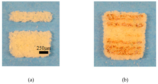
Figure 7.
An example of two defective layers caused by laser fluctuation at scanning speed of 50 mm/s or 100 mm/s. (a) incomplete layer at lower bound. (b) Discolored bone traces at upper bound.
The edges of the layers also curl upward under some process conditions. The raised regions can cause part shifting and other problems when spreading a fresh layer of material. As seen in Figure 8, layers processed at higher power levels have a significantly larger mass. These parts have greater handling strength, but the parts with higher mass curl more. For a fixed laser power and line spacing, the scanning speed is also found to impact both layer mass and layer flatness (see Figure 9). The curling of the edges occurs when the top surface of the powder bed experiences higher temperatures than the depth and temperature gradient curls the layer upward as the top surface shrinks faster than the bottom [23]. This phenomenon can also be caused by premature crystallization of polymers. This limits the use of higher laser power to improve layer integrity [24].
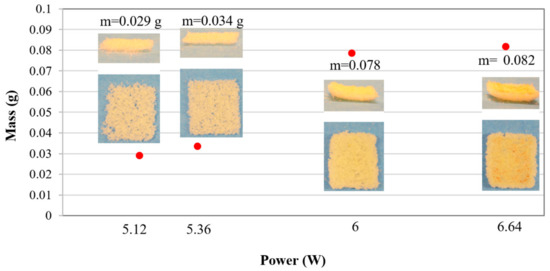
Figure 8.
The effect of power increment on the amount of fused material and distortion of 1 cm primitive layers. The process was performed at focal distance = 51 mm, laser scan speed = 150 mm/s, and line spacing = 100 μm. The images on the graph show the side and top view of the primitive layers.
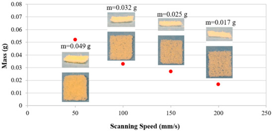
Figure 9.
The effect of laser scanning speed on the amount of fused material and distortion of 1 cm primitive layers. The process was performed at a constant power of 5.36 W, focal distance = 51 mm, and line spacing = 100 μm. The images on the graph show the side and top view of the primitive layers.
Looking at both figures reveals that by increasing the laser power, more material is cured in depth of powder bed. This increases the layer weight, but after a threshold causes warpage. So, the best process setting for manufacturing DBM/PCL scaffolds at ambient temperature cannot be determined solely based upon samples’ weight (thickness) because severe curling occurs for excessively cohesive layers. The process setting has to meet a combination of DBM discoloration requirements, acceptable cohesion, plus minimal warpage in the layers.
3.3. Optimized Processing Parameters
By incorporating the observations of the single layer primitive study, it is concluded that for processing at room temperature and with no preheated powder bed, the energy input must be maintained below the threshold that causes layer distortion. Among the processed layers, the following set of variables created the most favorable quality of the layer primitive: power = 5.36 W, line spacing = 100 μm, and scan speed = 150 mm/s. This set of variables falls in the safe operational window to process DBM particulates and was utilized to manufacture all tensile bars and cubes for further characterization. Unfortunately, these process parameters produce limited strength. Therefore, the initial fusion of the material to create the scaffold geometry was followed by an isothermal heat treatment to strengthen the parts as described below.
3.4. Dimensional Accuracy
The heat treatment of the samples in post-processing ensures that the PCL has melted throughout the part and improves the consolidation level in the samples. But, the heating shrinks the parts. To evaluate shrinkage, the sample height, gauge section, and the overall length of the tensile bars were measured before and after post-processing [25]. The shrinkage of the nine tensile bars that were printed was assessed directly after laser fusion is summarized in Table 1.

Table 1.
The dimensional deviation of the green samples from the CAD model. p = 5.36 W; spot size = 0.2 mm; line spacing = 100 μm.
The length of the tensile bar was very close to the target of 64 mm. The scanning was performed lengthwise along the tensile bar for scanning layers. The lateral heat conduction causes some material to stick to the edges of the print and make planar green dimensions turn out slightly greater than the CAD model. It should be noted that since the beam width is constant during printing, the amount of the neighboring material that sticks to the layer width and length is expected to be approximately similar. This dimensional increment results in a greater percentage error in the narrower part (gauge) of the sample. However, scan paths could be offset to compensate for this deviation. In addition, the beam movement inaccuracy, optical aberration, and beam scattering in the powder bed could be other sources of error [26]. The shrinkage in the thickness is highest as porosity between layers may be higher and gravity promotes the rearrangements in this direction [27].
The dimensional change of the samples from the desired CAD values is presented in Figure 10 as a function of the curing time. The samples undergo minimal shrinkage during the 3 h heat treatment. Samples cured for 5 and 7 h underwent comparable shrinkage though the variation between samples was reduced at the longer treatment. The longer treatment would be preferred because the initial model can be compensated to offset for the mean shrinkage; however, the variation becomes the error. The length has the smallest shrinkage. This is probably because the continuous scan of the laser along the sample length creates fully fused lines that resist shrinkage during post-processing. In these samples, every layer is scanned in the same direction so that this impact is clearly visible. If the scanning direction were varied by layer, the shrinkage would likely be reduced, but the part may distort during post-processing.
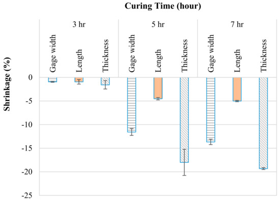
Figure 10.
Breakdown of curing shrinkage in different directions when cured for various times.
3.5. Tensile Strength Assessment
The heat treatment caused anisotropic shrinkage that varied with the heating time and is expected to influence the mechanical properties of the cured samples. The tensile strength of the samples was measured using an MTS 858 universal hydraulic testing system. In order to acquire accurate data, the grip section of the samples must not deform during testing. Thus, a low viscosity epoxy was infiltrated into the pores in the grip sections of the tensile bars and hardened overnight at room temperature. The induced tensile forces were measured with a 900 N load-cell at a grip displacement rate of 1.5 mm/min. An exemplary set of stress–strain curves for a 7 h heat-treated sample and a machined DBM strip is presented in Figure 11.
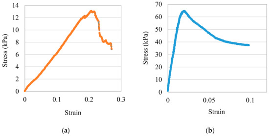
Figure 11.
The stress versus strain curve. (a). A machined DBM strip. (b) A 7 h post-processed sample.
Looking at the tensile test results (Figure 12) reveals that maximum tensile strength is linked to the curing time duration. The samples cured for 3 h have the least dimensional change and retain their weak mechanical property. The 5 h heat treatment increases tensile strength significantly as the molten PCL has more time to migrate into the DBM particles and increase adhesion. Longer heat treatment (7 h) slightly improves the tensile strength, which suggests that maximum tensile strength reaches a plateau beyond which further heating does not increase shrinkage. The tensile strength of the cancellous bone falls between that of the DBM/PCL composite samples with heat treatments of 3 h and 5 h. This suggests that the post-processing or the PCL composition could be tailored to match the mechanical properties of the natural DBM if desired.
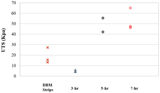
Figure 12.
The comparison of the maximum tensile strength of the heat-treated samples to the demineralized cancellous bone grafts.
Table 2 compares Young’s modulus (E) for DBM strips and the LS-fabricated parts with different post-processing times. It can be seen that the demineralized bone strips have the least Young’s modulus. For the produced samples, stiffness is tied to heat treatment duration. Stiffness increases significantly with increased curing time from 0.22 MPa after 3 h to 4.333 MPa after 7 h heat treatment. This could be due to the fact that longer heat treatments allow for more viscous sintering evolution or because the polymer chains have more time for crystallization, leading to a reduction in the extensibility of the polymer [28].
Table 2.
Young’s modulus of the heat-treated samples and cancellous bone grafts.
3.6. Density and Porosity Characterization
The density and pore channels in scaffolds are of paramount importance to regenerate the bone. Load distribution and proper biological functionality are closely linked to the void fraction and architecture of the pore network in the bone. These properties typically vary with location in the body [29]. The pore volume of bone and the scaffold samples were measured using helium pycnometry [30] and the skeletal density was calculated. Using these values, the density of PCL was estimated. Composite samples were fabricated at two DBM mass fractions (45%, 55%) to assess the composition sensitivity. Figure 13 demonstrates that the DBM fraction is proportionally related to the skeletal density of the final product. This confirms that there is minimal closed porosity in the manufactured samples that would reduce the measured density.
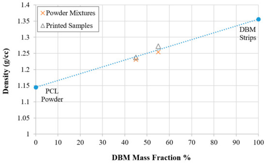
Figure 13.
The variation of the density based on the DBM content in the powder stock.
The MIP measurements, shown in Figure 14, indicate that, for the 45 wt % DBM and 55 wt % DBM blends, there is a similar trend as well as pore distribution through the scaffolds. It is also evident that the maximum pore size in both samples is ~250 μm.
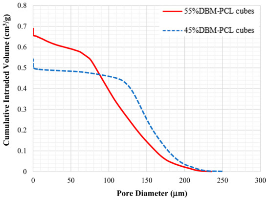
Figure 14.
The intrudable porosity of DBM/PCL hybrid scaffolds measured by the MIP instrument.
The density measurements and porosity summarized in Table 3 provide additional insight into the part structures. The skeletal density of the DBM/PCL composite cubes is comparable for pycnometry and MIP. The MIP additionally shows that there is significant open porosity (>40%) to support bone ingrowth. This porosity increases for higher DBM fractions. The DBM samples were not successfully measured using MIP due to the presence of very large pores and the possible collapse of the structure under pressure.
Table 3.
The density and void volume fraction measured by MIP.
It is evident that skeletal densities from gas pycnometry for 45 wt % DBM and 55 wt % DBM samples are is quite similar to what measured by MIP. The slight difference could result from the limitation of mercury to protrude the holes smaller than 3 nm, which might exist within the DBM particulates. On the other hand, helium can intrude almost all the pores thanks to the small molecular size. Another noteworthy point is that the higher content of DBM yields more porosity in the construct which may be the result of different DBM and PCL arrangements in the print and/or fine pores of the DBM particles.
The results indicate that CO2 laser is able to create a porous construct with DBM/PCL material and that the final mechanical properties, as well as porosity, highly depend on DBM fraction and post-processing conditions. These results could be extended by adjusting the composition ratios, using modified material systems such as adding biocompatible porogens or using more controlled powder morphology to adjust the balance between porosity and mechanical properties. In vitro and in vivo testing of the resultant parts to evaluate the biological features are preserved is another open question that awaits further study.
4. Conclusions
This work employed LS capability to process the DBM/PCL mixture. The required conditions to create the desired geometry by LS was determined. The flatness of the fused layer was a significant consideration in selecting the best set of processing parameters. For the selected process parameters, the prints showed good dimensional accuracy, but strength was insufficient for handling. The strength was improved by thermal post-processing at 65 °C. Shrinkage caused by heat treatment was significant but repeatable. The tensile strength and stiffness varied significantly with the post-processing times, and the tested conditions exceeded the strength of cancellous bone. Density of the composite samples and DBM matrix were measured by gas pycnometry and a mercury intrusion instrument. Density of the composite samples is comparable to cancellous bone. The results of the porosimetry indicate that LS has a great potential to fabricate temporary scaffolds containing natural bone particles with nearly 50% porosity. Further work is needed to evaluate the biological function of these composite materials and to verify that the DBM has not been damaged by the thermal processing.
Author Contributions
M.Z. performed the experiments and analyzed the data. A.M. provided guidance on the impact of clinical and regulatory requirements to the process and proposed the project goal. N.B.C. supervised the project and designed the methodology to accomplish this research. M.Z. and N.B.C. wrote the paper. All authors have read and agreed to the published version of the manuscript.
Funding
This research was funded by the LifeLink foundation.
Acknowledgments
The authors gratefully acknowledge the assistance of J.H. and G.C. in measuring the melting point of the PCL, Craig Lusk for use of the laser system, and A.Z. and D.M. for using the MIP instrument to determine the density and porosity of the samples.
Conflicts of Interest
The authors declare no conflicts of interest.
References
- Ziaee, M.; Hershman, R.; Mahmood, A.; Crane, N.B. Fabrication of Demineralized Bone Matrix/Polycaprolactone Composites Using Large Area Projection Sintering (LAPS). J. Manuf. Mater. Process. 2019, 3, 30. [Google Scholar] [CrossRef]
- Sheikh, Z.; Hamdan, N.; Ikeda, Y.; Grynpas, M.; Ganss, B.; Glogauer, M. Natural graft tissues and synthetic biomaterials for periodontal and alveolar bone reconstructive applications: A review. Biomater. Res. 2017, 21, 9. [Google Scholar] [CrossRef] [PubMed]
- Aitken, G.; Gordon, H. Benefits and associated risks of using allograft, autograft and synthetic bone fusion material for patients and service providers—A Systematic Review. JBI Database Syst. Rev. Implement. Rep. 2010, 8, 1–13. [Google Scholar]
- Piaia, L.; Salmoria, G.V.; Hotza, D. Chapter 10 - Additive manufacturing of nanostructured bone scaffolds. In Nanostructured Biomaterials for Cranio-Maxillofacial and Oral Applications; Souza, J.C.M., Hotza, D., Henriques, B., Boccaccini, A.R., Eds.; Elsevier: Florianópolis, Brazil, 2018; pp. 181–210. [Google Scholar]
- Shirazi, S.F.S.; Gharehkhani, S.; Mehrali, M.; Yarmand, H.; Metselaar, H.S.C.; Adib Kadri, N.; Osman, N.A.A. A review on powder-based additive manufacturing for tissue engineering: Selective laser sintering and inkjet 3D printing. Sci. Technol. Adv. Mater. 2015, 16, 033502. [Google Scholar] [CrossRef]
- Gibson, I.; Rosen, D.; Stucker, B. Additive Manufacturing Technologies, 2nd ed.; Springer: Boston, MA, USA, 2015. [Google Scholar]
- Lykov, P.A.; Sapozhnikov, S.B.; Shulev, I.S.; Zherebtsov, D.A.; Abdrakhimov, R.R. Composite Micropowders for Selective Laser Sintering. Metallurgist 2016, 59, 851–855. [Google Scholar] [CrossRef]
- Tiwari, S.K.; Pande, S.; Bobade, S.M.; Kumar, S. Assessment of mechanical properties and flammability of magnesium oxide/PA12 composite material for SLS process. Rapid Prototyp. J. 2019, 25, 176–186. [Google Scholar] [CrossRef]
- Wu, H.; Sun, Y.; Peng, J.; Huang, C.; Ye, X. Effect Of Processing Parameters On Dimensional Accuracy And Bending Strength Of Graphite Flake/Phenolic Resin Powder Mixture In SLS Process. Proc. Inst. Mech. Eng. Part C J. Mech. Eng. Sci. 2019, 233. [Google Scholar] [CrossRef]
- Zhao, K.; Deng, Y.; Chun Chen, J.; Chen, G.-Q. Polyhydroxyalkanoate (PHA) scaffolds with good mechanical properties and biocompatibility. Biomaterials 2003, 24, 1041–1045. [Google Scholar] [CrossRef]
- Loh, Q.L.; Choong, C. Three-Dimensional Scaffolds for Tissue Engineering Applications: Role of Porosity and Pore Size. Tissue Eng. Part B Rev. 2013, 19, 485–502. [Google Scholar] [CrossRef]
- Mazzoli, A. Selective Laser Sintering In Biomedical Engineering. Med. Biol. Eng. Comput. 2013, 51, 245–256. [Google Scholar] [CrossRef]
- Barlow, J.W. Selective Laser Sintering of Calcium PhosphatePowders. In Proceedings of the 1994 International Solid Freeform Fabrication Symposium, SFF, Austin, TX, USA, 8–10 August 1994. [Google Scholar]
- Tan, K.H.; Chua, C.K.; Leong, K.F.; Cheah, C.M.; Cheang, P.; Abu Bakar, M.S.; Cha, S.W. Scaffold Development Using Selective Laser Sintering of Polyetheretherketone–Hydroxyapatite Biocomposite Blends. Biomaterials 2003, 24, 3115–3123. [Google Scholar] [CrossRef]
- Crump, S.S. Apparatus And Method For Creating Three-Dimensional Objects. U.S. Patent 5121329, 9 June 1992. [Google Scholar]
- Craft, G.; Nussbaum, J.; Crane, N.; Harmon, J.P. Impact of extended sintering times on mechanical properties in PA-12 parts produced by powderbed fusion processes. Addit. Manuf. 2018, 22, 800–806. [Google Scholar] [CrossRef]
- Hung, B.P.; Naved, B.A.; Nyberg, E.L.; Dias, M.; Holmes, C.A.; Elisseeff, J.H.; Dorafshar, A.H.; Grayson, W.L. Three-Dimensional Printing of Bone Extracellular Matrix for Craniofacial Regeneration. ACS Biomater. Sci. Eng. 2016, 2, 1806–1816. [Google Scholar] [CrossRef] [PubMed]
- Spears, T.G.; Gold, S.A. In-process sensing in selective laser melting (SLM) additive manufacturing. Integr. Mater. Manuf. Innov. 2016, 5, 2. [Google Scholar] [CrossRef]
- Mahesh Mani, B.M.L.; Donmez, M.A.; Feng, S.C.; Moylan, S.P.; Fesperman, R.R. Measurement Science Needs for Real-time Control of Additive Manufacturing Powder Bed Fusion Processes. Int. J. Prod. Res. 2016. [Google Scholar] [CrossRef]
- Yadroitsev, I.; Bertrand, P.; Smurov, I. Parametric analysis of the selective laser melting process. Appl. Surf. Sci. 2007, 253, 8064–8069. [Google Scholar] [CrossRef]
- Kull, K.L.; Bass, R.W.; Craft, G.; Julien, T.; Marangon, E.; Marrouat, C.; Harmon, J.P.E. Synthesis and characterization of an ultra-soft poly(carbonate urethane). Eur. Polym. J. 2015, 71, 510–522. [Google Scholar] [CrossRef]
- Wang, C.M.D.Y.; Tofig, G.A.; Cunningham, R.W.; Pearson, R.A. Selective Laser Sintering Processing Behavior of Polyamide Powders. In Proceedings of the SPE ANTEC 2017, Anaheim, PA, USA, 8–10 May 2017. [Google Scholar]
- Zeng, X.D.Z.; Cui, J.; Jiang, J.H.; Yan, S.; Peng, B. Improvement on Selective Laser Sintering and Post-Processing of Polystyrene. Polymers 2019, 11, 11. [Google Scholar] [CrossRef]
- Schmid, M.; Amado, A.; Wegener, K. Polymer powders for selective laser sintering (SLS). AIP Conf. Proc. 2015, 1664, 160009. [Google Scholar]
- Bajric, S. Selective Laser Sintering Of Pa2200: Effects Of Print Parameters On Density, Accuracy, And Surface Roughness; Los Alamos National Lab: Los Alamos, NM, USA, 2017. [Google Scholar]
- McVey, R.W.; Melnychuk, R.M.; Todd, J.A.; Martukanitz, R.P. Absorption of laser irradiation in a porous powder layer. J. Laser Appl. 2007, 19, 214–224. [Google Scholar] [CrossRef]
- Korner, C.; Bauereib, A.; Attar, E. Fundamental consolidation mechanisms during selective beam melting of powders. Model. Simul. Mater. Sci. Eng. 2013, 21, 14. [Google Scholar] [CrossRef]
- Menyhárd, A.; Suba, P.; László, Z.; Feketem, H.M.; Mester, Á.O.; Horváth, Z.; Vörös, G.; Varga1, J.; Móczó, J. Direct correlation between modulus and the crystalline structure in isotactic polypropylene. Express Polym. Lett. 2015, 9, 308–320. [Google Scholar] [CrossRef]
- Yoon, B.-H.; Koh, Y.-H.; Park, C.-S.; Kim, H.-E. Generation of Large Pore Channels for Bone Tissue Engineering Using Camphene-Based Freeze Casting. J. Am. Ceram. Soc. 2007, 90, 1744–1752. [Google Scholar] [CrossRef]
- Zein, I.; Hutmacher, D.W.; Tan, K.C.; Teoh, S.H. Fused deposition modeling of novel scaffold architectures for tissue engineering applications. Biomaterials 2002, 23, 1169–1185. [Google Scholar] [CrossRef]
© 2020 by the authors. Licensee MDPI, Basel, Switzerland. This article is an open access article distributed under the terms and conditions of the Creative Commons Attribution (CC BY) license (http://creativecommons.org/licenses/by/4.0/).