Article

Process Stability during Laser Beam Welding with Beam Oscillation and Wire Feed

BIAS—Bremer Institut für angewandte Strahltechnik GmbH, Klagenfurter Straße 5, 28359 Bremen, Germany
J. Manuf. Mater. Process. 2019, 3(1), 17; https://doi.org/10.3390/jmmp3010017
Submission received: 20 December 2018 / Revised: 24 January 2019 / Accepted: 28 January 2019 / Published: 1 February 2019
(This article belongs to the Special Issue New Findings and Approaches in Machining Processes)

Abstract

:
Beam oscillation in laser material processing makes it possible to influence process behavior in terms of energy distribution, stability, melt pool dynamics and solidification. Within the setup presented here, the beam is oscillated transverse to the welding direction, and the filler wire is fed to the melt pool of a butt joint with an air gap. One advantage of this setup is the large gap bridging ability. Certain parameter sets lead to the so-called buttonhole welding method, which allows laser welding of smooth and nearly ripple-free seams. Observations showed a transition area between conventional keyhole and buttonhole welding in which the process is destabilized. Welds made with parameter sets from this area contain critical seam defects. Welding experiments with high-speed video recording and a simplified analytical model about the wire-beam interaction have helped to elucidate the mechanisms behind this. EN AW-6082 sheet material in 1.5 mm thickness and ML 4043 filler wire with 1.2 mm diameter were used. The investigations lead to the conclusion that partially melted wire segments result at certain parameter relations which hinder the formation of a buttonhole. If these segments are prevented, buttonhole welding occurs. In the transition area, these segments are very small and can lead to the detachment of a buttonhole, resulting in the named seam defects.

1. Introduction

Aluminum is a key material which is increasingly being used for lightweight structures, especially in transport industries [1]. Its advantages are low density combined with high specific strength [2]. However, many aluminum alloys have hot cracking susceptibility if they are welded [3]. This has to be considered in the design of parts and process development [4] along with further seam characteristics such as porosity or the strength reduction in the weld metal and heat affected zone. Model-based predictions of the porosity or resulting strength are given by Wu et al. [5]. One typical method to influence seam properties is to add filler wire with beneficial elements to the melt pool [6]. For laser welding with aluminum, the addition of a filler wire is often indispensable [7]. The laser is a widely used tool in welding technologies featuring low distortion and high production efficiency [8]. Its concentrated energy focus on the material surface allows deep penetration welding due to the existence of a keyhole [9]. An example for the formation of a keyhole during welding was modeled by Cho et al. in [10]. Keyhole laser welding is a well-established process in the production industry for several types of joint configurations or material thicknesses; it makes possible the treatment of complex 3D parts [11]. However, the gap bridging ability often limits the applicability of laser beam welding [12] due to its small laser spot of ~10 µm to ~600 µm. To apply the advantages of high beam intensities, normally an air gap width of less than 10% of the sheet thickness is required to ensure a stable process [7]. The consequences are low manufacturing tolerances or an overlapping part design, both of which increase the cost of production. To prevent welding distortion due to long seams, often, difficult and expensive clamping is necessary to ensure a fixed part position. Even when using stitch welding, it is difficult to avoid a gap completely [13]. Sun et al. [14] investigated the gap bridging ability for welding with CO2 lasers. They welded 2 mm thick carbon steel sheets in a butt joint configuration. By adding filler wire, the gap bridging ability increased to 1 mm. They showed that precise positioning between the laser beam, the filler wire and the air gap is the key factor for a stable process [14]. Aalderink et al. [12] investigated the gap bridging ability of solid-state lasers for different process combinations (one beam, double beam, laser MIG-hybrid (MIG—metal inert gas), with and without wire feed). They welded aluminum sheets in a butt joint configuration and revealed that the addition of filler wire increases the ability of gap bridging from 0.2 mm to 0.6 mm in case of one-beam processes. Investigations in terms of laser beam welding with filler wire are given by Binroth [15]. His analytical model describes the heat transfer from the laser beam to the wire and enables the prediction of wire feed rates in which a continuous wire melting occurs and a smooth material transfer into the melt pool is achieved. He classified the melting conditions in periodical droplet formation (too much heat input), continuously melting (good heat input) and insufficient melting (insufficient heat input) [15].
With the use of oscillation, it is possible to influence the process behavior by deflecting the laser beam at a high frequency by a few millimeters [16]. General mathematical descriptions of 1D and 2D beam trajectories during beam oscillation are given and discussed in [17]. Beam oscillation during laser welding generally decreases the penetration depth compared to conventional laser welding [18]. Kraetzsch et al. show that an increasing oscillation width increases the mixing ratio by the laser welding of aluminum and copper in an overlap joint. Unfortunately, this is accompanied by increased porosity [19]. Göbel et al. [20] conducted experimental investigations about the influence of a circular oscillated laser beam on narrow gap multi-pass welding with filler wire. They concluded that circular beam scanning significantly increases the positioning tolerance of the filler wire. In a further report on their investigations, they state that high circular scanning frequencies between 400 Hz and 700 Hz lead to turbulences in the melt pool and sinusoidal solidification shapes, which are disadvantageous for following weld layers [21]. Investigations of high frequency beam oscillation up to 1500 Hz on the melt pool behavior of aluminum showed that humping effects could be prevented while enabling a higher welding speed [17]. In addition, the gap bridging ability for butt joint welding can be increased by up to 190% of the sheet’s thickness by using a beam oscillation transverse to the welding direction in combination with filler wire and a single-mode fiber laser [22]. When changing the laser source to a multi-mode fiber laser with a spot diameter that is about 4-times larger, a gap bridging ability of 100% of the sheet thickness is possible [23]. It was concluded that it is beneficial for stable gap bridging, when the sheet edges are molten by direct beam irradiation to enable confluence between the molten sheet edges and molten wire material. Wide process windows and high positioning tolerances were observed in both cases. Within these investigations, an instability was observed, like the one described by Eriksson et al. [24]. This instability is a catenoidally-shaped, large hole in the melt pool which follows the melt pool front as an enlarged keyhole, which is called ‘donut laser welding’ [25]. The width of the catenoid is nearly the width of the melt pool, since further growth is hindered by solid material [26]. The pressures in such a self-sustaining hole are of surface tensional nature [26]. While with ‘donut laser welding’ [18], the catenoid represents an enlarged keyhole, experiments of Vollertsen [27] and Cho et al. [28] clearly show a keyhole and a separated catenoidal shaped hole in the melt pool, which is called ‘buttonhole’ here. Both welding experiments and CFD (Computational Fluid Dynamics) simulations showed this effect. In [27], experiments showed that the formation of a ‘buttonhole’ correlated with the oscillation frequency, which is confirmed by numerical simulations in [29]. An example for buttonhole welding is given in [30]. Generally, the ‘buttonhole’ moves with the welding speed at the melt pool front and separated the melt pool into two areas. In the front, a keyhole exists being responsible for high melt pool dynamics. The liquid metal in the front of the melt pool must flow around the ‘buttonhole’ to reach the rear area [30]. High speed videos have shown that the ‘buttonhole’ absorbs most of the melt pool dynamics enabling the solidification of a smooth and ripple free seam surface in the rear part [30]. The melt can solidify very smoothly, making buttonhole welding suitable for the production of visible seams [31] such as visible seams on the rear [32] lids or on car roofs [33]. The process development based on wire melting and bead on plate welding experiments, as well as process windows for welding with and without ‘buttonholes’ are presented in [31].
The following requirements must be met to enable the formation of a stable buttonhole [31]:
  • full penetration through the sheet material;
  • the melt pool must be wider than the sheet thickness;
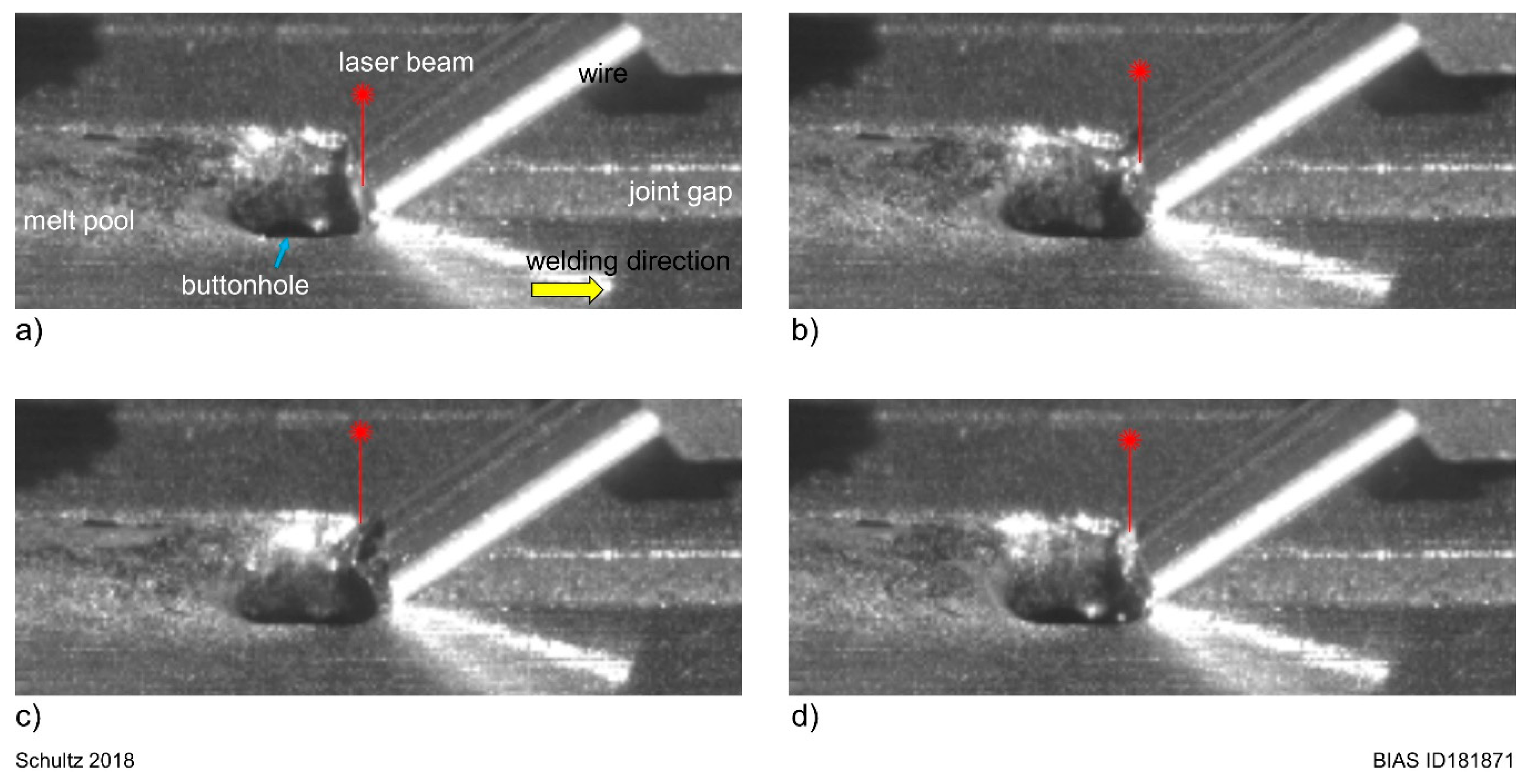
  • oversized melt pool widths lead to buttonhole destabilization and the risk of pinholes;
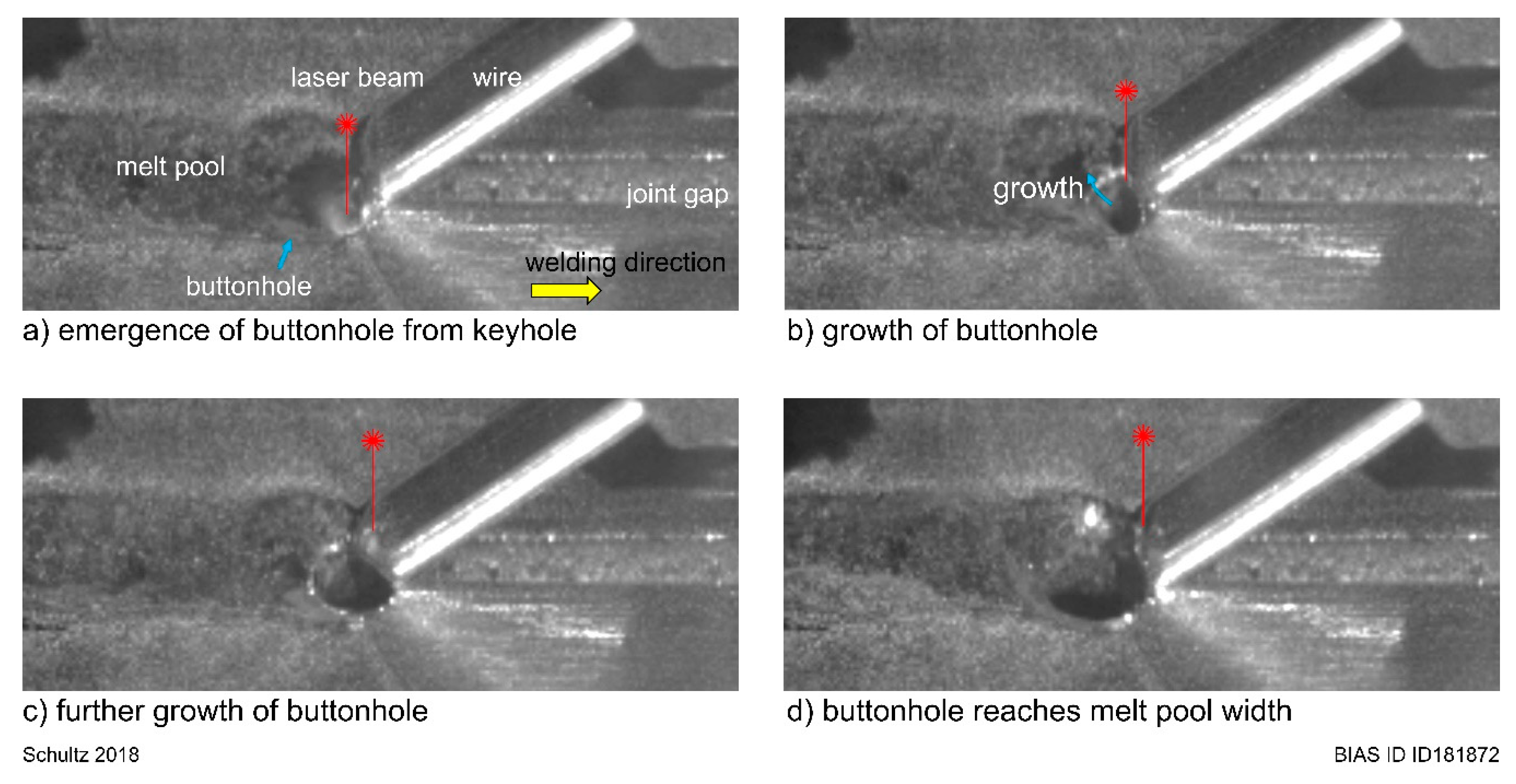
  • radii conditions of front and rear buttonhole determine the movement, elongation and constriction [30].
Experiments showed that a transition area between keyhole welding and buttonhole welding exists [27]. Welding with parameter sets from the transition area leads to an instable process and welds with critical seam defects [31]. Observations indicate that the specific transition area especially occurs while welding with wire feed. The emphasis of this work is to clarify the unknown mechanisms behind the unstable transition area. For this purpose, an analytical model of the wire-beam interaction and welding experiments are presented and discussed in this paper. The quality of the weld is evaluated visually, by metallographic inspection and by CT (computed tomography) analysis.

2. Modelling

Figure 1 illustrates the beam path over the filler wire and Equation (1) described the path function Ω ( x ) .
Ω D ( x ) = b O s 2 cos ( 2 π f O s x v D cos ( φ D ) )
Here, b O s describes the oscillation width and f O s the oscillation frequency. The movement speed of the wire through the transvers oscillating laser beam equals the wire feed speed v D multiplied with the cosine term of the feed angle cos ( φ D ) . Accordingly, one beam period has the length v D cos ( φ D ) / f O s . If the oscillation width is wider than the wire diameter, the interaction length on one side of the wire is decreased to the length s D .
Along the path Ω ( x ) , the laser beam will create a keyhole with a surrounding layer of liquid material. It is assumed here that keyhole and layer are cylindrically shape with a constant diameter, and that they completely penetrate through the wire. This is called ‘beam interaction cylinder’ here, from which the ‘beam interaction circle’ is visible on the wire surface. Along the movement path, the beam interaction circle will leave a melt track behind. Figure 2 shows different schematic melt tracks on a wire for different parameter sets. In the first case of Figure 2a, the melt track does not overlap at the sides of the wire. In this case the overlapping term ψ D is smaller than zero. This leads to unmolten wire segments in the intermediate area. To avoid this kind of segments, either the diameter of the beam interaction cylinder ξ D (Figure 2b) or the oscillation frequency (Figure 2c) has to be increased, or the wire feed speed has to be decreased. Thus, overlapping of the melt track occurs ( ψ D > 0 ).
If ξ D equals the distance s D from Figure 1, the overlapping term ψ D will be zero ( ψ D = 0 ). This case is the transition point from “no overlapping” to “overlapping”. It is described with Equation (2)
ξ D = s D
The distance s is calculated with Equation (3), when considering the boundary conditions Ω D ( x s 1 ) = d D / 2 and x s 1 = v D cos ( φ D ) acos ( d D b O s ) / 2 π f O s from Figure 1.
s = v D cos ( φ D ) f O s 2 x s 1 = v D cos ( φ D ) f O s ( 1 acos ( d D b O s ) π )
It follows Equation (4) solved to v D , when inserting Equation (3) in Equation (2).
v D = ξ D f O s cos ( φ D ) ( 1 acos ( d D b O s ) π )

3. Setup and Methods

The used laser source for experiments was a TruDisk12002. The welding head was a Trumpf BEO D70 (TRUMPF Laser- und Systemtechnik GmbH, Ditzingen, Germany) upgraded with an ILV DC-Scanner system (ILV Dipl.-Ing. Alfred G. Arlt, Schwalbach, Germany) to apply one-dimensional beam oscillation transverse to the welding direction. Figure 3 illustrates the welding head from two sides. A mirror redirected the collimated beam towards the work piece. The mirror oscillates along its z-axis and therefore applies a beam oscillation transverse to the welding direction. The beam focusing occurs afterwards. The combination of a collimation, as well as a focusing length of 200 mm, led to a nominal beam diameter of 200 µm using this laser source. The magnification in Figure 3a shows a cross sectional view of the butt joint with air gap and provided filler wire. Shielding gases for the upper bead and the root were argon and helium, respectively.
A Dinse DIX WD300 and WDE300 “push-push” feed system (Dinse GmbH, Hamburg, Germany) delivered the filler wire in a leading configuration. The process was observed by a high-speed camera Vision Research Phantom VEO410 (Vision Research, Wayne, NJ, USA) with a recording sample rate of 8000 fps. The sheet material was the aluminum alloy EN AW-6082 (AlSi1MgMn) with a sheet thickness of 1.5 mm. Filler wire was ML 4043 with 1.2 mm diameter. Table 1 lists the process parameters. For each parameter set a specific laser power was determined which led to a complete penetration through the sheet material to fulfil the given requirements for buttonhole welding. Seam widths were determined with a Keyence Digital Microscope VHX (Keyence Deutschland GmbH, Neu-Isenburg, Germany).
The determination of the diameter of the beam interaction circle ξ D was determined experimentally with images from high-speed camera recordings (Figure 4). Five measurements were taken for each experimental row. The measurement results are given with Figure 5. It can be seen that the diameter of the beam interaction circle is quite similar for all parameter sets.
.
Metallurgical investigations were carried out on metallographic seam cross-sections and CT (General Electric—phoenix v|tome|x m) analysis for selected welds. Aim was to evaluate the seam formation and possible weld defects such as pores or cracks. The CT analysis was conducted on seam sections of approximately 25 mm length.

4. Experimental Results

Figure 6 shows three images from the welding process as captured with high-speed video camera. All welds were made with a constant process parameter set, except the oscillation frequency. Depending on the oscillation frequency, either a keyhole process (Figure 6a), an unstable process with remaining weld defects (Figure 6b) or buttonhole welding was obtained (Figure 6c). In the case of keyhole and buttonhole welding, the gap of 1 mm was bridged successfully.
Figure 7 shows the process magnification at different states from Figure 6a. The emergence and collapse of a small buttonhole before reaching self-sustainability are shown. Figure 7a shows the birth of the buttonhole from the keyhole. In the next image, the laser beam is on its path towards the other side of the melt pool. Herby, it moves over the wire in the direction of the black arrow. Figure 7b shows that the wire tip is not completely melted by direct laser irradiation. A small segment stays solid and melts in the melt pool within milliseconds (Figure 7c,d). Nevertheless, the buttonhole cannot grow under these conditions and immediately collapses again (Figure 7c). This event is repeated along the whole welding process.
The emergence of a self-sustaining buttonhole is shown in Figure 8, which is a magnification from Figure 6b. The birth from the keyhole is given in Figure 8a. The buttonhole grows afterwards within a few milliseconds to the width of the melt pool. Here, the wire tip is completely melted by direct laser beam irradiation.
The detachment of a self-sustaining buttonhole is shown in Figure 9. It is the second close examination from the shown welding in Figure 6b. In Figure 9a, the buttonhole moves with the process and is attached to the process front. In Figure 9b, it may be observed that the left buttonhole wall solidified. The melt starts damming in front of the buttonhole (Figure 9c), and finally, leads to its detachment, Figure 9d. As a result, a pinhole remains in the weld.
A stable buttonhole process is shown in Figure 10, as seen in Figure 6c. The image sequence shows one oscillation period of the beam. In comparison to Figure 7, the wire tip is melted continuously, and the material transfer is evenly distributed into the melt pool. Both buttonhole channels are liquid along the hole, thus, enabling continuous melt flow through the channels. The buttonhole was stable throughout the whole process.
Figure 11, Figure 12 and Figure 13 show typical upper beads from welding experiments. Each figure contains welds made with constant welding and wire feed speed. Within the figure, the observed three typical welding conditions are shown. Welds from buttonhole welding are slightly thinner and almost ripple free compared to those from keyhole welding. Welds from the transitions area remained mostly with pinholes and undercuts. Here, the width shows a strong variance. Furthermore, as shown in Figure 12b, the transition from keyhole to buttonhole welding was observed. No remaining pinholes were observed. In Figure 14 several classified welds were summarized as an overview in a diagram. The alternating process behavior in dependence of the oscillation frequency can also be observed for every parameter row.
Figure 15 shows metallographic cross-sections from selected welds from keyhole and buttonhole welding. It can be seen that the wire and base material are mixed homogeneously. It is interesting that the welds from keyhole welding are wider and lower than those from buttonhole welding. The welds from buttonhole welding both seem to have a height to width ration that is nearly 1. The cross-section from welding with an oscillation frequency of 120 Hz has small edge notches on upper bead and root, where the largest one is 48 µm deep. Nevertheless, they are all small enough to fulfill the highest seam quality level requirements for weld evaluation from DIN EN ISO 13919-2:2001-12. The same quality assignment applies for the evaluation of the reinforcements of upper bead and root. In the cross-sections of the buttonhole welds, small pores can be identified. The largest one has a diameter of 79 µm. Further porosity investigations on the same welds were carried out by CT analysis, Figure 16. The porosity is colored in dependence of the pore Volume here. It can be seen that the porosity in welds from keyhole welding are both beneath 0.00 vol.-%. In contrast to this, buttonhole welded seams have pores in both cases. At an oscillation frequency of 120 Hz, the porosity is at 0.06 vol.-%. At 150 Hz the porosity doubles up to 0.12 vol.-%. According to DIN EN ISO 13919-2:2001-12, 3% porosity is acceptable to fulfill the highest quality group for porosity evaluation. All specimens were free of cracks.

5. Discussion

5.1. Model Validity and Sensitivity

Figure 17 shows Figure 14 overlapped with Equation (4) considering parameters form Table 1 and Figure 4. It can be seen that the calculation runs through the transition area where crosses describe the process instabilities.
The accordance between the calculated transition line and experimental results for an unstable process is plotted in Figure 18. A slight overestimation of the calculated value can be determined with increasing oscillation frequency.
Simplifications for the model (Equation (5)) are generally based on the used keyhole geometry due to its complexity in reality. Here, a cylinder consisting of a keyhole surrounded by liquid material which completely penetrates trough the wire is assumed. These prerequisites suitable laser power settings were not considered in Equation (5). Nevertheless, a suitable laser power for buttonhole welding can be found by simple wire melting and bead on plate experiments [31].
The beam interaction circle considered in this work is assumed to keep a constant diameter during the welding process. In reality, it will decrease with increasing penetration depth on the one hand and vary along the oscillation path due to a varying trajectory speed on the other. One possible approach to the model requirements is to use laser parameters from which a complete penetration is ensured during welding at all-time.
Figure 17 shows that the model is sensitive regarding the diameter of the beam interaction circle, especially with increasing wire feed speed or oscillation frequency. This also seems valid for the transition area from welding without and with ‘buttonhole’. The wide ranges for the beam interaction circle diameter, as visible in Figure 5, can be attributed to the determination method. The diameter changes its geometry very dynamically, which has a strong influence on the measurements. Nevertheless, the mean deviation between model and experiment is around 10%.
A different way to learn about the process is by using numerical simulation, see e.g., [28]. This brings additional information e.g., about melt pool flow and temperature. Nevertheless, it is shown here that a simplified analytical model in combination with experiments can be used to better understand process behavior.

5.2. Instabilities during Laser Welding with Beam Oscillation

Instabilities during laser welding with beam oscillation are generally present in the transition area from welding without or with ‘buttonhole’ (see Figure 14). Next to the transition area, a stable process is present. The combination of observations from welding experiments and findings from model calculations (Equation (4)) lead to the conclusion that the wire melting condition changes within the transition area, causing process instabilities.
An even wire melt occurs if the overlapping term fulfils ψ D > 0 . In this case, the wire tip is melted completely by direct laser irradiation, see Figure 10.
If overlapping is not present, solid wire segments overtake the oscillating laser beam. The size of these solid segments increases with decreasing ψ D (prerequisite ψ D < 0 ). They will also melt over time, but until they do, they prevent the buttonhole from growing to a self-sustaining size. Both model (Figure 2) and high-speed images (Figure 7) confirm this. The buttonhole collapses again due to unfavorable surface tensional pressure conditions, see [31]. It has to be noted here that CFD simulations show a similar effect for a similar welding process [28].
Within the transition area, the size of unmelted wire segments in the melt pool are so small that the emergence of a buttonhole is not hindered every time. If a buttonhole grows to self-sustainability, it is not disturbed any more by unmolten wire segments. Nevertheless, the melt flow channels next to the sides of the buttonhole solidify and lead to melt damming, and accordingly, to the detachment of the buttonhole. A pinhole remains in the weld if the buttonhole does not collapse before solidification (see Figure 13b).

6. Conclusions

The wire-beam interaction during laser welding with beam oscillation and filler wire feed was investigated. The following conclusions are made:
  • solid wire segments can overtake the oscillating laser beam at e.g., low oscillation frequencies and prevent a buttonhole from growing to a self-sustaining size;
  • for buttonhole welding, an even melt of the wire tip is required.
Metallurgical evaluations of keyhole and buttonhole welding were carried out and compared to each other. The following points are concluded:
  • buttonhole welding has an influence on solidification behavior (height to width ratio results near a value of 1);
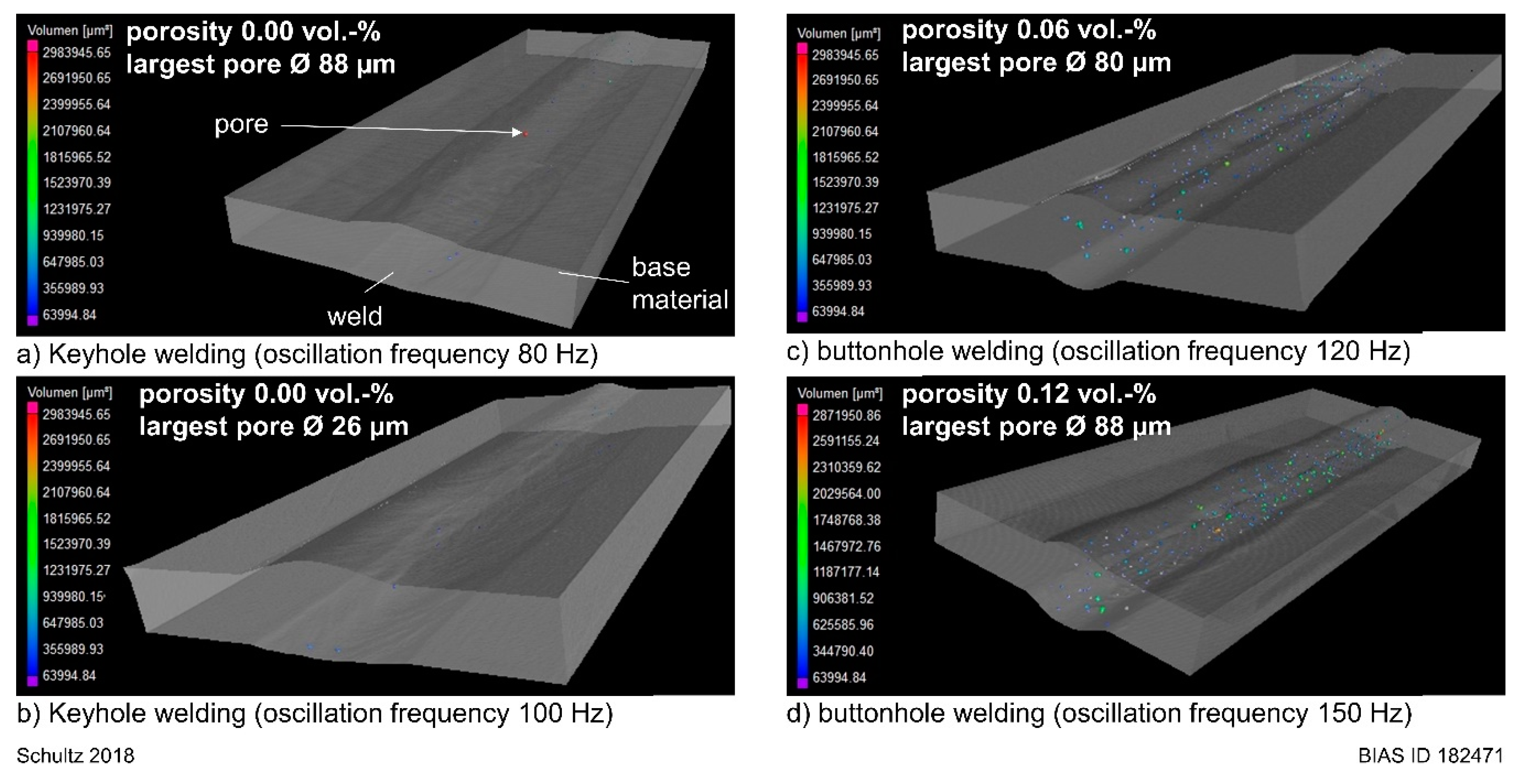
  • buttonhole welding can lead to a fine porosity of the seam.

Funding

This work was accomplished within the Center of Competence for Welding of Aluminum Alloys CentrAl. Funding by the Deutsche Forschungsgemeinschaft (DFG, German Research Foundation, project number 290705638) is gratefully acknowledged.

Acknowledgments

I would like to thank Tim Radel and Peer Woizeschke for their support.

Conflicts of Interest

The author declares no conflict of interest.

References

  1. EAA—European Aluminium Association. Aluminium in Cars—Unlock the Light-Weighting Potentials; European Aluminium Association: Brussels, Belgium, 2015; pp. 5–11. [Google Scholar]
  2. Reisgen, U.; Olschok, S.; Wagner, N.; Zäh, M.; Oefele, F.; Ruhstorfer, M. Aktuelle Fügeverfahren für Aluminiumwerkstoffe. DVS Bericht Strahlschweißen von Aluminium 2010, 266, 22–27. [Google Scholar]
  3. Dilthey, U. Schweißtechnische Fertigungsverfahren 2; Springer-Verlag: Berlin, Germany, 2005; Volume 229. [Google Scholar]
  4. Matthes, J. Schweißtechnik: Schweißen von metallischen Konstruktionswerkstoffen; Fachbuchverlag Leipzig im Carl Hanser Verlag: Leipzig, Germany, 2006. [Google Scholar]
  5. Wu, S.C.; Yu, X.; Zuo, R.Z.; Zhang, W.H.; Xie, H.L.; Jiang, J.Z. Porosity, Element Loss, and Strength Model on Softening Behavior of Hybrid Laser Arc Welded Al-Zn-Mg-Cu Alloy with Synchrotron Radiation Analysis. Weld. J. 2013, 92, 64–71. [Google Scholar]
  6. Seefeld, T.; Schultz, V. New developments in filler wire assisted laser joining of Aluminium. In Proceedings of the LAMP2013—6th International Congress on Laser Advanced Materials Processing, Niigata, Japan, 23–26 July 2013. [Google Scholar]
  7. Salminen, A. The filler wire—Laser beam interaction during laser welding with low alloyed steel filler wire. Mechanika 2010, 84, 67–74. [Google Scholar]
  8. Hatwig, J.; Reinhart, G.; Zaeh, M.F. Automated task planning for industrial robots and laser scanners for remote laser beam welding and cutting. Prod. Eng. Res. Deve 2010, 4, 327–332. [Google Scholar] [CrossRef]
  9. Vollertsen, F. Properties and Prospects of High Brightness Solid State Lasers. Laser Tech. J. 2009, 6, 27–31. [Google Scholar] [CrossRef]
  10. Cho, W.-I.; Na, S.-J.; Thomy, C.; Vollertsen, F. Numerical simulation of molten pool dynamics in high power disk laser welding. J. Mater. Process. Technol. 2012, 212, 262–275. [Google Scholar] [CrossRef]
  11. Calleja, A.; Tabernero, I.; Fernández, A.; Celaya, A.; Lamikiz, A.; López de Lacalle, L.N. Improvement of strategies and parameters for multi-axis laser cladding operations. Opt. Lasers Eng. 2014, 56, 113–120. [Google Scholar] [CrossRef]
  12. Aalderink, B.J.; Pathiraj, B.; Aarts, R.G.K.M. Seam gap bridging of laser based processes for the welding of aluminium sheets for industrial applications. Int. J. Adv. Manuf. Technol. 2010, 48, 143–154. [Google Scholar] [CrossRef]
  13. Liu, Q.S.; Mahdavian, S.M.; Aswin, D.; Ding, S. Experimental study of temperature and clamping force during Nd: YAG laser butt welding. Opt. Laser Technol. 2009, 41, 794–799. [Google Scholar] [CrossRef]
  14. Sun, Z.; Kuo, M. Bridging the joint gap with wire feed laser welding. J. Mater. Process. Technol. 1999, 87, 213–222. [Google Scholar] [CrossRef]
  15. Binroth, C. Beitrag zur Prozeßstabilität beim CO2-Laserstrahlschweißen von Aluminium mit Zusatzwerkstoff. Ph.D. Thesis, University Bremen Strahltechnik Band 1, BIAS Verlag, Bremen, Germany, 1995. [Google Scholar]
  16. Albert, F.; Starcevic, D. Möglichkeiten zur Beeinflussung der Nahtrauheit beim Laserstrahlschweißen von Türen und Klappen aus Aluminium. In Proceedings of the 10th conference on Laser-Anwenderforum (LAF’16), Bremen, Germany, 23–24 November 2016. [Google Scholar]
  17. Schweier, M.; Haubold, M.W.; Zaeh, M.F. Analysis of spatters in laser welding with beam oscillation. CIRP J. Manuf. Sci. Technol. 2016, 14, 35–42. [Google Scholar] [CrossRef]
  18. Berend, O.; Haverkamp, H.; Meier, O.; Engelbrecht, L. High-frequency beam oscillating to increase the process stability during laser welding with high melt pool dynamics. In Proceedings of the 24th ICALEO Conference, Miami, FL, USA, 31 October–3 November 2005; pp. 1032–1041. [Google Scholar]
  19. Kraetzsch, M.; Standfuss, J.; Klotzbach, A.; Kaspar, J.; Brenner, B.; Beyer, E. Laser Beam Welding with High-Frequency Beam Oscillation: Welding of Dissimilar Materials with Brilliant Fiber Lasers. Laser Manuf. Phys. Procedia 2011, 12, 142–149. [Google Scholar] [CrossRef] [Green Version]
  20. Göbel, G.; Brenner, B.; Beyer, E. New Application Possibilities for Fiber Laser Welding. In Proceedings of the 26th International Congress on Application of Lasers & Electro-Optics, ICALEO 2007, Orlando, FL, USA, 29 October–1 November 2007; pp. 102–108. [Google Scholar]
  21. Dittrich, D.; Schedewy, R.; Brenner, B.; Standfuß, J. Laser-multi-pass-narrow-gap-welding of hot crack sensitive thick Aluminium plates. Laser Manuf. Phys. Procardia 2013, 41, 225–233. [Google Scholar]
  22. Schultz, V.; Seefeld, T.; Vollertsen, F. Gap Bridging Ability in Laser Beam Welding of Thin Aluminum Sheets. In Proceedings of the 8th International Conference on Photonic Technologies (LANE 2014), Physics Procedia, Munich, Germany, 8–11 September 2014; Schmidt, M., Vollertsen, F., Merklein, M., Eds.; Elsevier B.V.: Amsterdam, The Netherlands, 2014; Volume 56, pp. 545–553. [Google Scholar]
  23. Schultz, V.; Seefeld, T.; Vollertsen, F. Spaltüberbrückbarkeit beim Laserstrahl-schweißen mit Strahloszillation. Schweißen und Schneiden 2015, 67, 518–522. (In Germany) [Google Scholar]
  24. Ericsson, I.; Powell, J.; Kaplan, A. Surface tension generated defects in full penetration laser keyhole welding. J. Laser Appl. 2014, 26, 012006. [Google Scholar] [CrossRef]
  25. Haglund, P.; Eriksson, I.; Powell, P.; Kaplan, A. Surface tension stabilized laser welding (donut laser welding)—A new laser welding Technique. J. Laser Appl. 2013, 25, 031501. [Google Scholar] [CrossRef]
  26. Aalderink, B.J.; de Lange, D.F.; Aarts, R.G.K.M.; Meijer, J. Keyhole shapes during laser welding of thin metal sheets. J. Phys. D Appl. Phys. 2007, 40, 5388–5393. [Google Scholar] [CrossRef]
  27. Vollertsen, F. Loopless Production: Definition and Examples from Joining. In Proceedings of the 69th IIW Annual Assembly and International Conference, Melbourne Convention Exhibition Centre, Melbourne, Australia, 10–15 July 2016. [Google Scholar]
  28. Cho, W.-I.; Schultz, V.; Woizeschke, P. Numerical study of the effect of the oscillation frequency in buttonhole welding. J. Mater. Process. Technol. 2018, 261, 202–212. [Google Scholar] [CrossRef]
  29. Cho, W.-I.; Schultz, V.; Vollertsen, F. Simulation of the buttonhole formation during laser welding with wire feeding and beam oscillation. In Proceedings of the Lasers in Manufacturing (LIM17), Munich, Germany, 26–29 June 2017. [Google Scholar]
  30. Schultz, V.; Woizeschke, P. High Seam Surface Quality in Keyhole Laser Welding: Buttonhole Welding. J. Manuf. Mater. Process. 2018, 2, 78. [Google Scholar] [CrossRef]
  31. Schultz, V.; Cho, W.-I.; Woizeschke, P.; Vollertsen, F. Laser deep penetration weld seams with high surface quality. In Proceedings of the Lasers in Manufacturing (LIM17), Munich, Germany, 26–29 June 2017. [Google Scholar]
  32. Tang, Z.; Seefeld, T.; Vollertsen, F. Laser Brazing of Aluminum with a new filler wire AlZn13Si10Cu4. Phys. Procedia 2013, 41, 128–136. [Google Scholar] [CrossRef]
  33. Engelbrecht, L. Umstieg von YAG auf Diode: Mehr Prozessstabilität, weniger Kosten beim Laserlöten der Dachnullfuge mit angepassten Strahleigenschaften. In Proceedings of the European Automotive Laser Applications (EALA), Bad Neuheim, Germany, 2 February 2009. [Google Scholar]
Figure 1. Interaction of the transverse oscillated beam with the filler wire.
Jmmp 03 00017 g001
Figure 2. Melt track for different parameter sets.
Jmmp 03 00017 g002
Figure 3. Schematic illustration of the welding process setup, adapted from [6].
Jmmp 03 00017 g003
Figure 4. Determination of the diameter of the beam interaction circle ξ D .
Jmmp 03 00017 g004
Figure 5. Diameter of beam interaction circle in dependence of parameter set.
Jmmp 03 00017 g005
Figure 6. Different welding conditions observed by a high-speed video camera (welding speed 2 m/min, wire feed speed 4 m/min, oscillation width 1.4 mm).
Jmmp 03 00017 g006
Figure 7. Sequence excerpt from high-speed video recording. Wire segments hindering growth of buttonhole (welding speed 2 m/min, wire feed speed 4 m/min, oscillation width 1.4 mm, oscillation frequency 80 Hz).
Jmmp 03 00017 g007
Figure 8. Emerge of buttonhole (welding speed 2 m/min, wire feed speed 4 m/min, oscillation width 1.4 mm, oscillation frequency 100 Hz).
Jmmp 03 00017 g008
Figure 9. Detachment of buttonhole (welding speed 2 m/min, wire feed speed 4 m/min, oscillation width 1.4 mm, oscillation frequency 100 Hz).
Jmmp 03 00017 g009
Figure 10. Even wire melting during buttonhole welding (welding speed 2 m/min, wire feed speed 4 m/min, oscillation width 1.4 mm, oscillation frequency 150 Hz).
Jmmp 03 00017 g010
Figure 11. Weld results for different oscillation frequencies (Parameters: laser power 2 kW; welding speed 2 m/min; wire feed speed 4 m/min; oscillation width 1.4 mm).
Jmmp 03 00017 g011
Figure 12. Weld results for different oscillation frequencies (Parameters: laser power 3 kW; welding speed 3 m/min; wire feed speed 6 m/min; oscillation width 1.4 mm).
Jmmp 03 00017 g012
Figure 13. Weld results for different oscillation frequencies (Parameters: laser power 4 kW; welding speed 4 m/min; wire feed speed 8 m/min; oscillation width 1.4 mm).
Jmmp 03 00017 g013
Figure 14. Resulting weld condition in dependence on the parameter set.
Jmmp 03 00017 g014
Figure 15. Metallographic cross-sections from welds from keyhole and buttonhole welding (Parameters: laser power 2 kW; welding speed 2 m/min; wire feed speed 4 m/min; oscillation width 1.4 mm).
Jmmp 03 00017 g015
Figure 16. CT analysis from keyhole and buttonhole welding (Parameters: laser power 2 kW; welding speed 2 m/min; wire feed speed 4 m/min; oscillation width 1.4 mm).
Jmmp 03 00017 g016
Figure 17. Transition range. Comparison between experiment and calculation.
Jmmp 03 00017 g017
Figure 18. Comparison between experimental and calculated data.
Jmmp 03 00017 g018
Table 1. Process parameters.
Row Laser   Power   P L   [ kW ] Welding   Speed   v s   [ m / min ] Wire   Feed   Speed   v D   [ m / min ] Feed   Angle   φ D   [ ° ] Oscillation   Width   b O s   [ mm ] Oscillation   Frequency   f O s   [ Hz ] Joint   Gap   b [mm]
r1224351.480 to 1501
r2336351.4100 to 2501
r3448351.4100 to 2501

