Kinematically Coupled Force Compensation—Experimental Results and Advanced Design for the 1D-Implementation †

Abstract
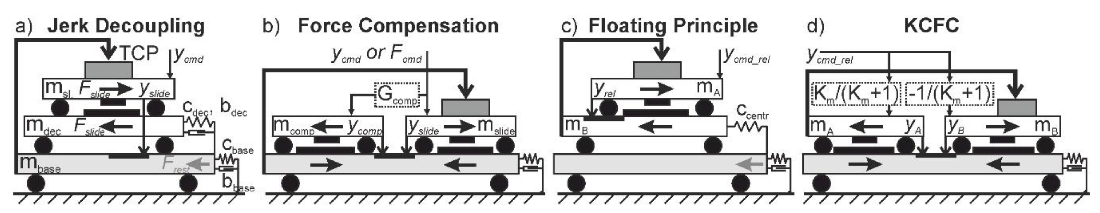
:1. Introduction
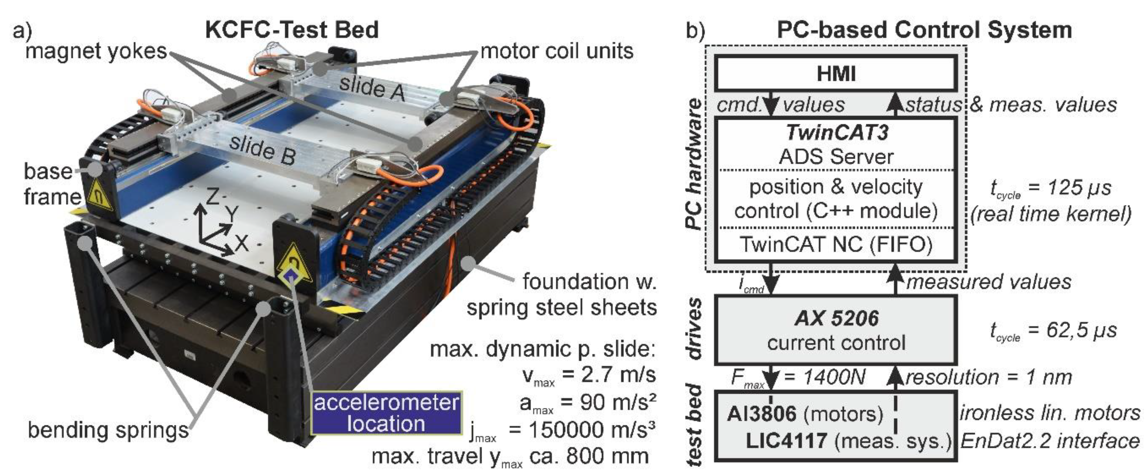
2. Test Bed for the Experimental Investigation of 1D-KCFC
2.1. Mechanical Design
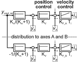
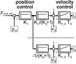
2.2. Control Concept for the 1D-KCFC Implementation
2.3. Experimental Characterisation and Modelling of the 1D-KCFC Test Bed
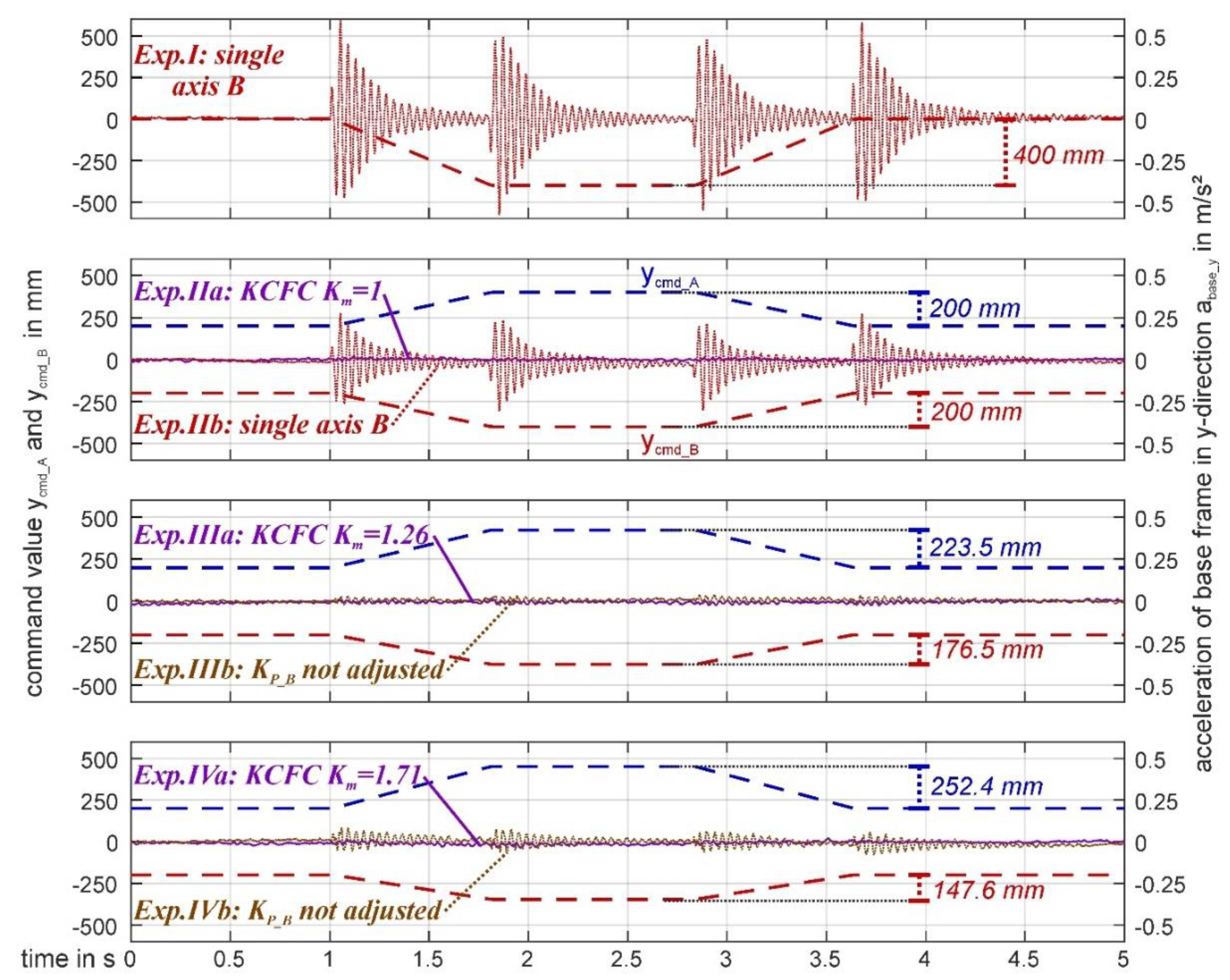
3. Experimental Investigation of the Effectiveness of the KCFC on the Test Bed
3.1. Experimental Procedure and Evaluation in the Time Domain
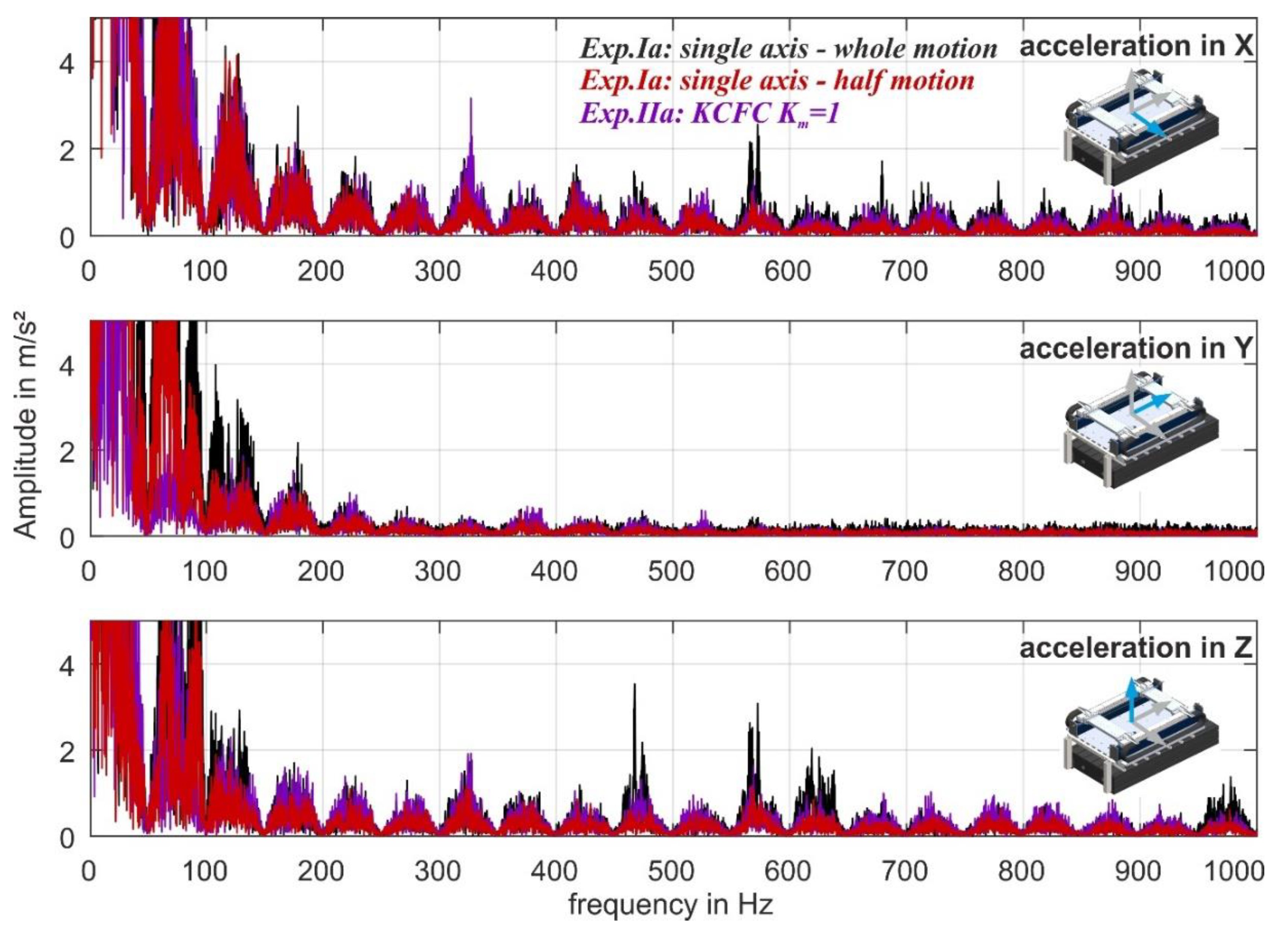
3.2. Evaluation in the Frequency Domain
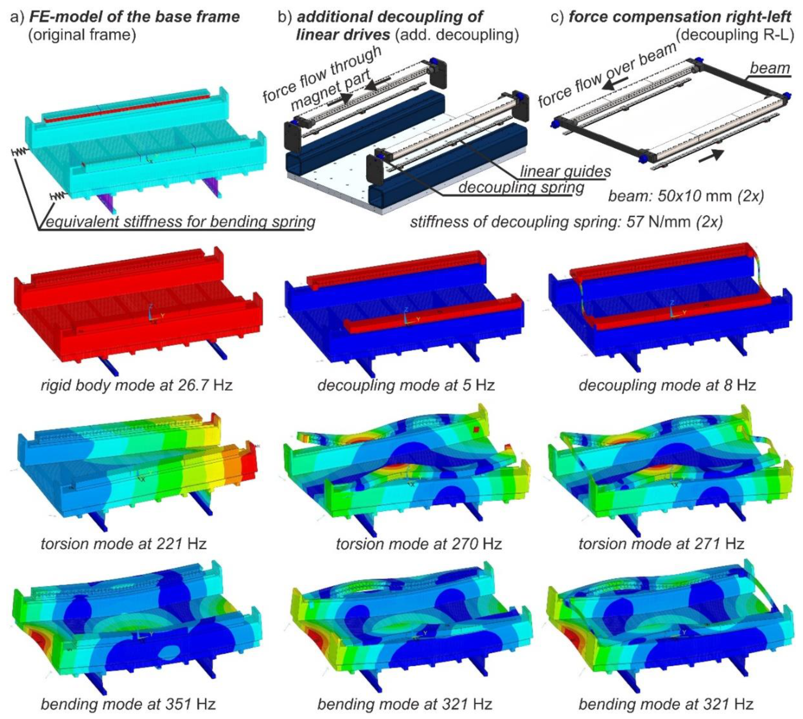
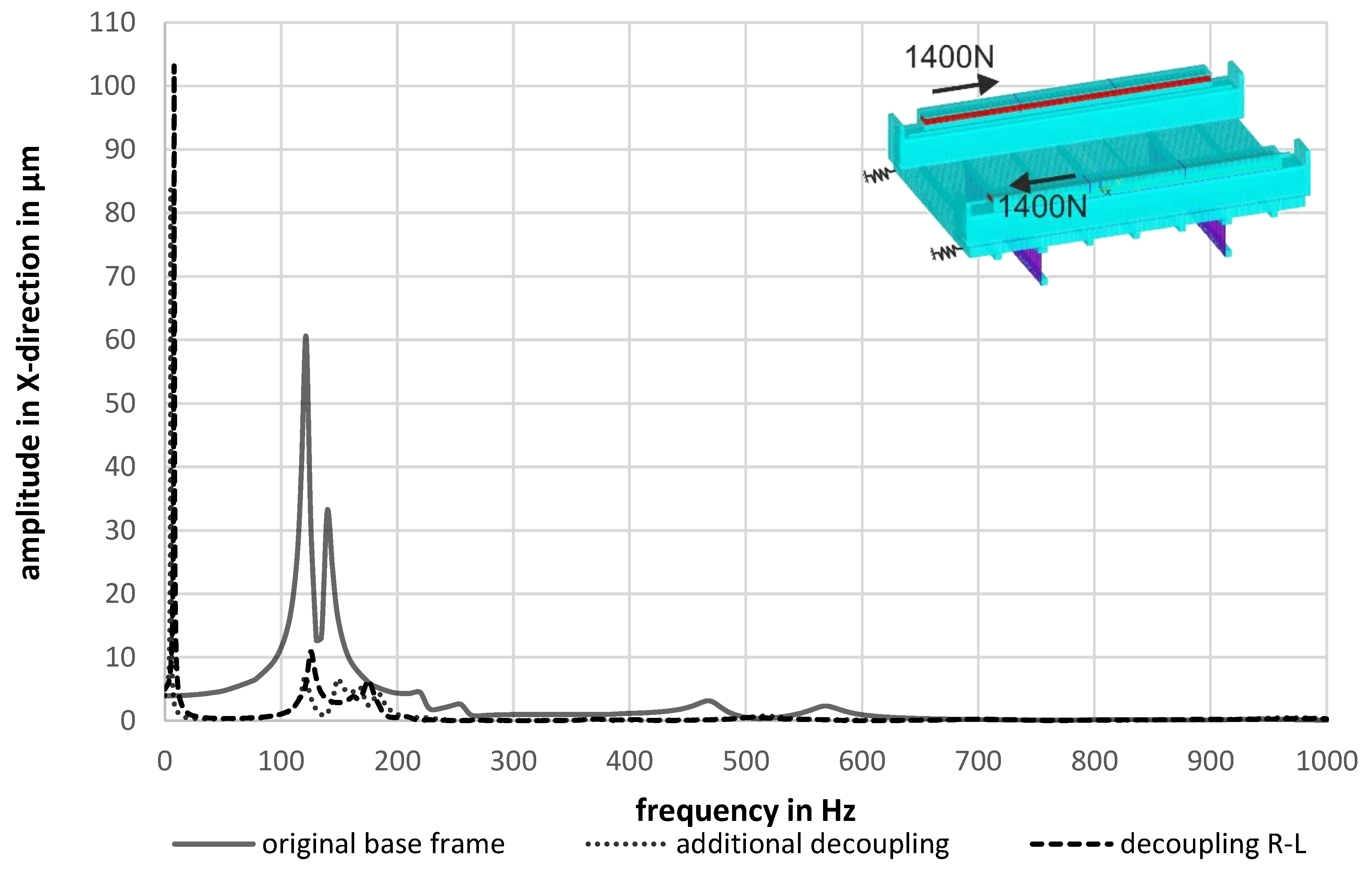
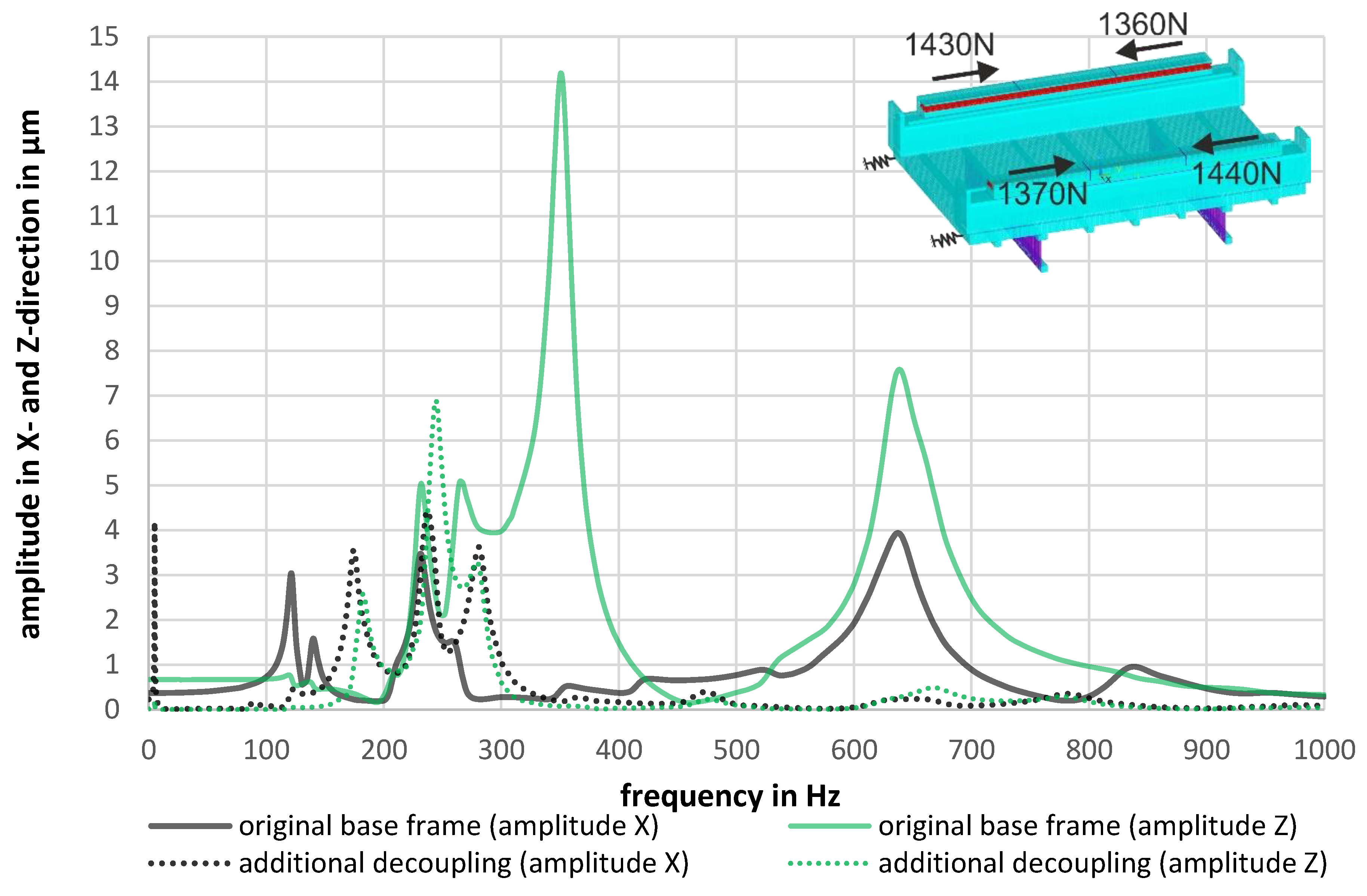
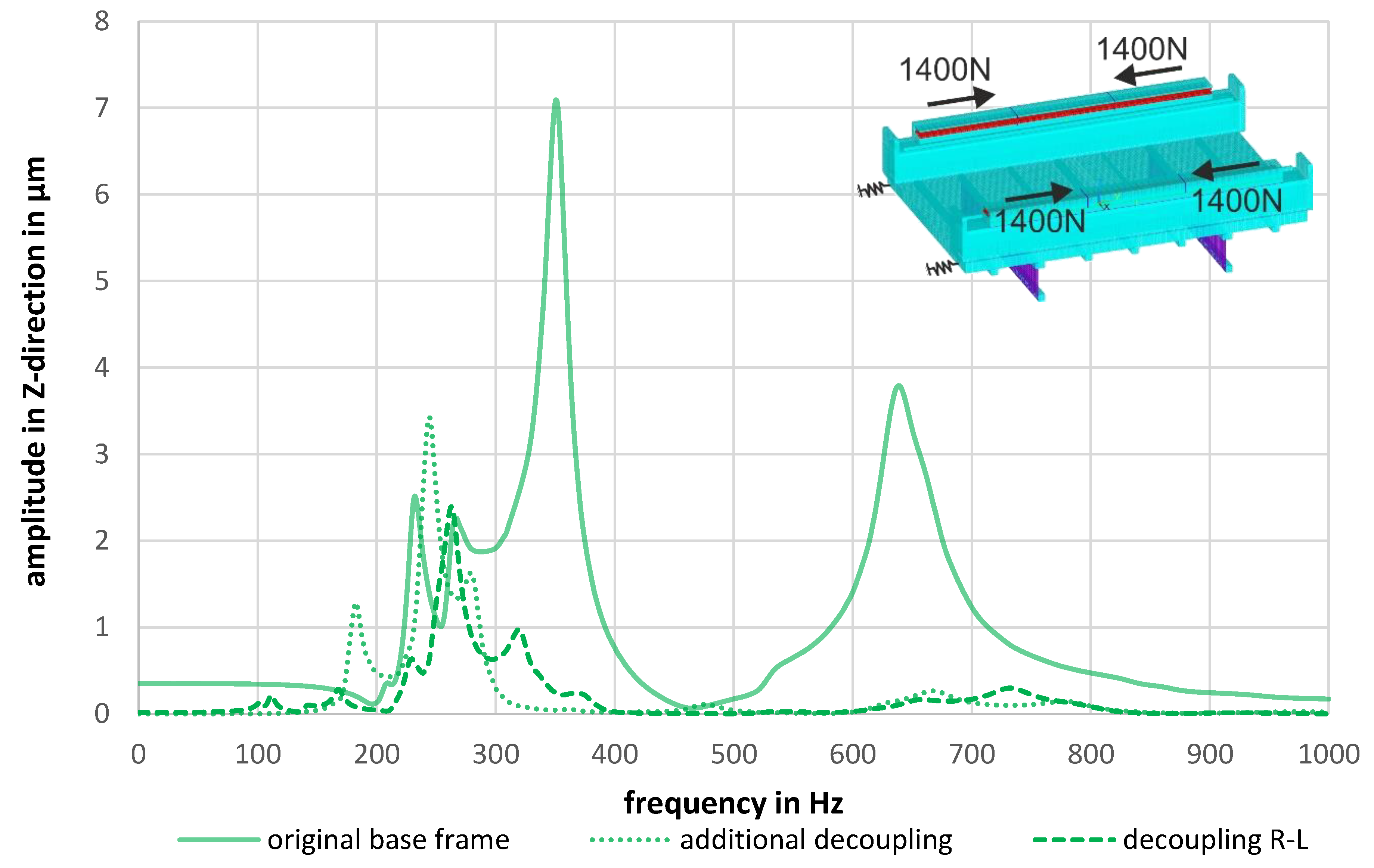
4. Advanced Design Concepts for Optimal Force Flow in KCFC Arrangements
5. Discussion
6. Conclusion and Outlook
- KCFC is quite complex and costly compared to competing principles, but seems to be suitable for processes with the highest dynamic requirements;
- The redundant axis arrangement of the KCFC enables the implementation of various structural and control concepts, which may permit an improved adaptation of the machine system to high dynamic processes with negligible process forces;
- The compensation effect of the 1D-KCFC could be verified by the experiments presented in this paper. It could be proven that the method is sufficiently robust against small parameter deviations of the moving masses (<20 %). In case of higher parameter deviations, the parameterisation of the control must be adapted (velocity gain KP), which may be done by means of identification algorithms;
- With the presented approach of mechanical decoupling of the force conducting parts, a further improvement of the compensation quality seems possible, even with unconsidered parameter deviations or in a non-collinear drive arrangement.
7. Patents
Author Contributions
Funding
Conflicts of Interest
Appendix A

| Parameter | Variable | Value | Parameter | Variable | Value |
|---|---|---|---|---|---|
| position control cycle | Tpos | 125 µs | acc. feed-forward | Kacc | 0.00 |
| velocity control cycle | Tvel | 125 µs | current limit | Ilim | 11.3 A |
| current control cycle | Tcurr | 62.5 µs | voltage limit | Ulim | 325 V |
| curr. control prop. gain | KI_curr | 84.0 V/A | motor resistance | Rmot | 7.9 V/A |
| curr. contr. integr. const. | TI_curr | 0.80 ms | motor inductivity | Lmot | 0.014 Vs/A |
| vel. feed-forward factor | Kvel | 1.00 | motor force constant | Kmot | 124 N/A |
| vel. LP-filter | Tvel | 0.00 ms | back-EMF constant | KEMF | 124 Vs/m |
References
- Altintas, Y.; Verl, A.; Brecher, C.; Uriarte, L.; Pritschow, G. Machine tool feed drives. CIRP Ann. 2011, 60, 779–796. [Google Scholar] [CrossRef]
- Brecher, C.; Wenzel, C.; Klar, R. Characterization and optimization of the dynamic tool path of a highly dynamic micromilling machine. CIRP J. Manuf. Sci. Technol. 2008, 1, 86–91. [Google Scholar] [CrossRef]
- Wang, Z.G.; Cheng, X.; Nakamoto, K.; Kobayashi, S.; Yamazaki, K. Design and development of a precision machine tool using counter motion mechanisms. Int. J. Mach. Tools Manuf. 2010, 50, 357–365. [Google Scholar] [CrossRef]
- Bubak, A.; Soucek, P.; Zelený, J. New Principles for the Design of Highly Dynamic Machine Tools. In Proceedings of the International Conference ICPR-17, Blacksburg, Virginia, USA, 3–7 August 2003; Deisenroth, M.P., Ed.; pp. 1–10. [Google Scholar]
- Großmann, K.; Müller, J.; Merx, M. Verfahren und Vorrichtung zur Erzeugung einer Relativbewegung. German Patent DE102012101979B4, 15 February 2018. [Google Scholar]
- Großmann, K.; Müller, J.; Merx, M.; Peukert, C. Reduktion antriebsverursachter Schwingungen. Antriebstechnik Ant J. 2014, 4, 35–42. [Google Scholar]
- Hiramoto, K.; Hansel, A.; Ding, S.; Yamazaki, K. A Study on the Drive at Center of Gravity (DCG) Feed Principle and Its Application for Development of High Performance Machine Tool Systems. CIRP Ann. 2005, 54, 333–336. [Google Scholar] [CrossRef]
- Neugebauer, R.; Denkena, B.; Wegener, K. Mechatronic Systems for Machine Tools. CIRP Ann. 2007, 56, 657–686. [Google Scholar] [CrossRef]
- Parenti, P.; Bianchi, G.; Cau, N.; Albertelli, P.; Monno, M. A Mechatronic study on a Model-Based Compensation of Inertial Vibration in a High-Speed Machine Tool. J. Mach. Eng. 2011, 11, 91–104. [Google Scholar]
- Muñoa, J.; Mancisidor, I.; Loix, N.; Uriarte, L.G.; Barcena, R.; Zatarain, M. Chatter suppression in ram type travelling column milling machines using a biaxial inertial actuator. CIRP Ann. 2013, 62, 407–410. [Google Scholar] [CrossRef]
- Ihlenfeldt, S.; Müller, J.; Merx, M.; Peukert, C. Kinematically coupled Force Compensation—Experimental results for the 1D-implementation. In Proceedings of the XIVth International Conference on High Speed Machining, Donostia, San Sebastian, Spain, 17–18 April 2018. [Google Scholar]
- Ihlenfeldt, S.; Müller, J.; Merx, M.; Peukert, C. Kinematically Coupled Force Compensation—Design Principle and Control Concept for Highly-dynamic Machine Tools. Procedia CIRP 2016, 46, 189–192. [Google Scholar] [CrossRef]
- Ihlenfeldt, S.; Müller, J.; Merx, M.; Peukert, C. A Novel Concept for Highly Dynamic Over-Actuated Lightweight Machine Tools. In Reinventing Mechatronics: Proceedings of Mechatronics 2018; Glasgow, Scotland, UK, 19–21 September 2018; Yan, X., Bradley, D., Moore, P., Eds.; University of Strathclyde: Glasgow, UK, 2018; pp. 210–216. ISBN 978-1-909522-37-4. [Google Scholar]
- Merx, M.; Peukert, C.; Müller, J.; Ihlenfeldt, S. Kinematically Coupled Force-Compensation—Experimental and simulative investigation with a highly dynamic test bed. In WGP-Jahreskongress, Aachen, Germany, 5–6 October 2017; Schmitt, R., Schuh, G., Eds.; Apprimus: Aachen, Germany, 2017; pp. 383–390. ISBN 978-3-86359-555-5. [Google Scholar]
- Hellmich, A.; Hipp, K.; Schlegel, H.; Neugebauer, R. Parameter Identification of NC-Axes during Regular Operation of a Machine Tool. Adv. Mater. Res. 2014, 1018, 419–426. [Google Scholar] [CrossRef]


| Relative to Base Frame (RB) | Relative between Slides (RS) | External Reference (RE) | |
|---|---|---|---|
| arrangement of linear guides and linear measuring systems | 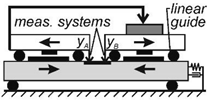 |  | 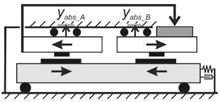 |
| Axis Control (A) | Superimposed Position Control (SP) | Superimposed Position and Velocity Control (SPV) |
|---|---|---|
 |  | 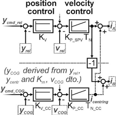 |
| Par. Set | mA | mB | Km | KP_A | KP_B | Motion Profile (Relative Motion) |
|---|---|---|---|---|---|---|
| I | not used | 30 kg | 1 | 50 As/m | 50 As/m | 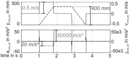 |
| IIa | 30 kg | 30 kg | 1 | 50 As/m | 50 As/m | |
| IIb | not used | 30 kg | 1 | 50 As/m | 50 As/m | |
| IIIa | 30 kg | 38 kg | 1.26 | 50 As/m | 63.3 As/m | |
| IIIb | 30 kg | 38 kg | 1.26 | 50 As/m | 50 As/m | |
| IVa | 30 kg | 51.3 kg | 1.71 | 50 As/m | 85.5 As/m | |
| IVb | 30 kg | 51.3 kg | 1.71 | 50 As/m | 50 As/m |
© 2019 by the authors. Licensee MDPI, Basel, Switzerland. This article is an open access article distributed under the terms and conditions of the Creative Commons Attribution (CC BY) license (http://creativecommons.org/licenses/by/4.0/).
Share and Cite
Ihlenfeldt, S.; Müller, J.; Merx, M.; Peukert, C. Kinematically Coupled Force Compensation—Experimental Results and Advanced Design for the 1D-Implementation. J. Manuf. Mater. Process. 2019, 3, 24. https://doi.org/10.3390/jmmp3010024
Ihlenfeldt S, Müller J, Merx M, Peukert C. Kinematically Coupled Force Compensation—Experimental Results and Advanced Design for the 1D-Implementation. Journal of Manufacturing and Materials Processing. 2019; 3(1):24. https://doi.org/10.3390/jmmp3010024
Chicago/Turabian StyleIhlenfeldt, Steffen, Jens Müller, Marcel Merx, and Christoph Peukert. 2019. "Kinematically Coupled Force Compensation—Experimental Results and Advanced Design for the 1D-Implementation" Journal of Manufacturing and Materials Processing 3, no. 1: 24. https://doi.org/10.3390/jmmp3010024
APA StyleIhlenfeldt, S., Müller, J., Merx, M., & Peukert, C. (2019). Kinematically Coupled Force Compensation—Experimental Results and Advanced Design for the 1D-Implementation. Journal of Manufacturing and Materials Processing, 3(1), 24. https://doi.org/10.3390/jmmp3010024