1. Introduction
Additive manufacturing (AM) offers the possibility to manufacture complexly-shaped and topographically-optimized components [
1,
2,
3,
4,
5]. Therefore, powder bed-based AM is contemplated to find application in various fields such as aviation, automotive, and biomedical engineering [
6]. Estimations state that 55% of all failures in aeronautic engineering and, generally speaking, about 90% of all engineering failures are caused by a fatigue-related damage mechanism [
7,
8]. Hence, it is of upmost importance to investigate and understand the fracture mechanisms and fatigue characteristics, to assess properly, as well as safely the material qualifications. It is crucial to take account of the interaction between the microstructure, internal defects, and fatigue resistance [
9,
10].
Inner imperfections like unmolten areas or bonding errors between melt-pool borders and pores are mostly responsible for fatigue failures concerning AM components. It is necessary to control the distribution and extension of such cavities, as they are preferable spots for fatigue crack initiation [
11,
12]. Given the fact that in the case of cast aluminum alloys, hot isostatic pressing (HIP) significantly decreases the volume fraction of porosity with only minor changes of microstructural features, leading to a considerable increase of fatigue strength, an appropriate post-treatment may be beneficial to AM parts, as well [
13,
14,
15,
16]. One can find that due to the extremely fine microstructure of selectively-laser-melted (SLM) parts, an HIP treatment above the solubility temperature of AlSi10Mg leads to microstructural coarsening because of the dissolving of grain boundaries. This results in a reduced fatigue resistance, although the porosity is significantly lower [
8,
17]. To take advantage of the beneficial effect of HIP on the porosity, the changes within the microstructure cause the necessity of quenching and a subsequent age hardening process to counteract these negative effects [
18]. The exact HIP parameter was determined incorporating the knowledge of the specimen manufacturer with the aim of reducing the amount of porosity in order to improve the fatigue behavior.
For this reason, the fatigue strength of the HIP-treated specimen at a commonly-used temperature for solution annealing followed by low temperature annealing as heat treatment was investigated. Besides their fatigue resistance, the local material properties, such as porosity and microstructure, were analyzed and compared to specimens without any post-treatment, denoted as the as-built condition.
2. Materials and Methods
The chemical composition of the utilized AlSi10Mg powder, shown in
Table 1, is given by the manufacturer specification and corresponds to the standard DIN EN 1706:2010 [
19].
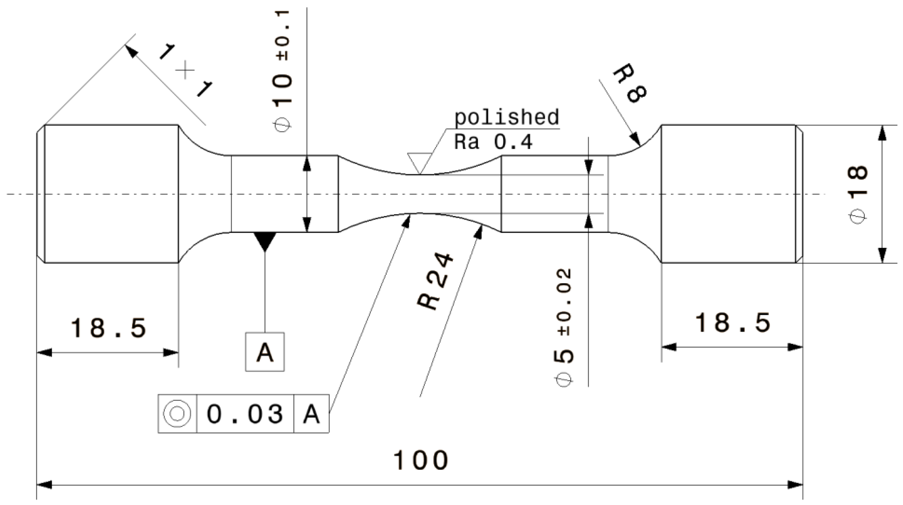
Specimens were fabricated using an EOS M290 system with a Yb fiber laser, a power of 400 W, and a beam diameter of 100 µm. All specimens were built in the vertical direction with a certain machining allowance in order to remove subsequently the as-built surface and eliminate surface-related effects. The structures were manufactured according to the standard parameter set given by the system and powder manufacturer EOS. Following the built process, hot isostatic pressing was performed applying a temperature higher than 500 °C and a pressure of above 100 MPa with a holding time of at least two hours followed by quenching under constant pressure. Low temperature annealing over a certain time period was conducted afterwards. Subsequent to the heat treatment, the specimens were processed to the final geometry by turning and polishing. A CAD drawing with the detailed specimen geometry and dimensions is shown in
Figure 1. The shape of the specimens was designed to show a homogeneous stress distribution over the cross-section with a stress concentration factor as low as possible due to the narrowing within the testing section, corresponding to no common standard.
The specimens are fatigue tested at a load stress ratio of R = −1 on a RUMUL Mikrotron resonant testing rig with a frequency of about 106 Hz. Collets were used for gripping in order to clamp the specimen at both ends. The abort criterion was defined either as total fracture or as run-out at 1 × 10
7 load cycles. Run-outs were reinserted at higher stress levels to obtain more data in the finite life regime, conservatively assuming pre-damaging at stress levels lower than the endurance limit [
20]. For each test series, respectively with and without HIP treatment, nine specimens were manufactured and tested.
3. Results and Discussion
3.1. Effect of HIP Treatment on the Microstructure
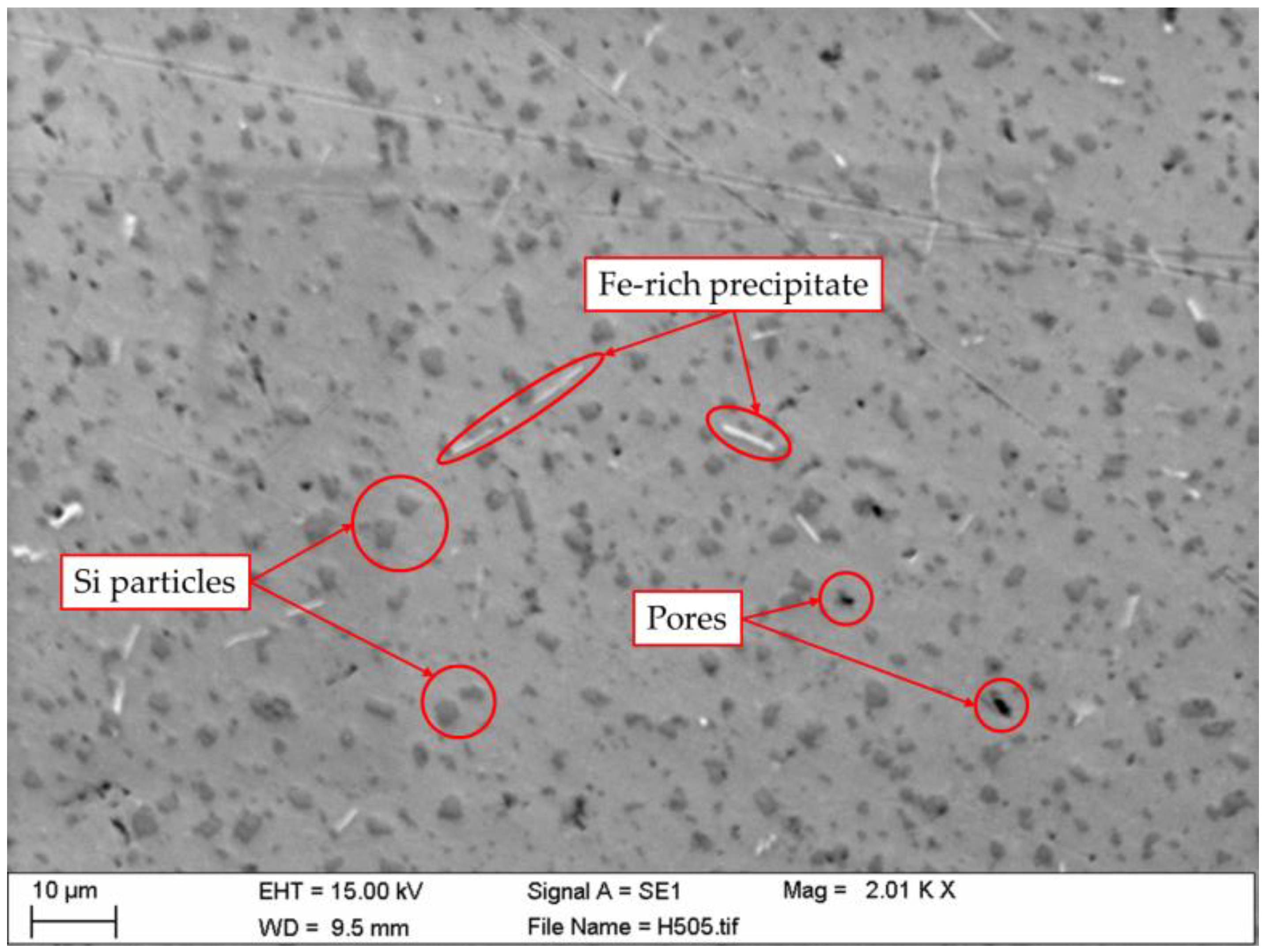
HIP treatment at high temperature with considerably high pressure leads to significant microstructural differences compared to the as-built condition; hence, the effect on the material was investigated in detail. To characterize the microstructure after HIP and heat treatment, SEM images, taken with a Carl Zeiss EVO MA 15 microscope, of the post-processed condition were evaluated. In
Figure 2, one can clearly see Fe-rich precipitates and Si particles, which were also detected in [
21]. Silicon crystals were precipitated at the grain boundaries during the HIP treatment above the solubility temperature, and they grew to their respective size during low temperature annealing [
22,
23,
24,
25]. Microstructural features like silicon agglomerations and needle-shaped, Fe-rich precipitates obstructed a propagating fatigue crack and, therefore, generally improved the resistance against fatigue crack growth. Such microstructures favor crack deflection and energy dissipation at the crack tip. Hence, the long crack growth was decelerated, whereby the fatigue strength was enhanced [
17,
26].
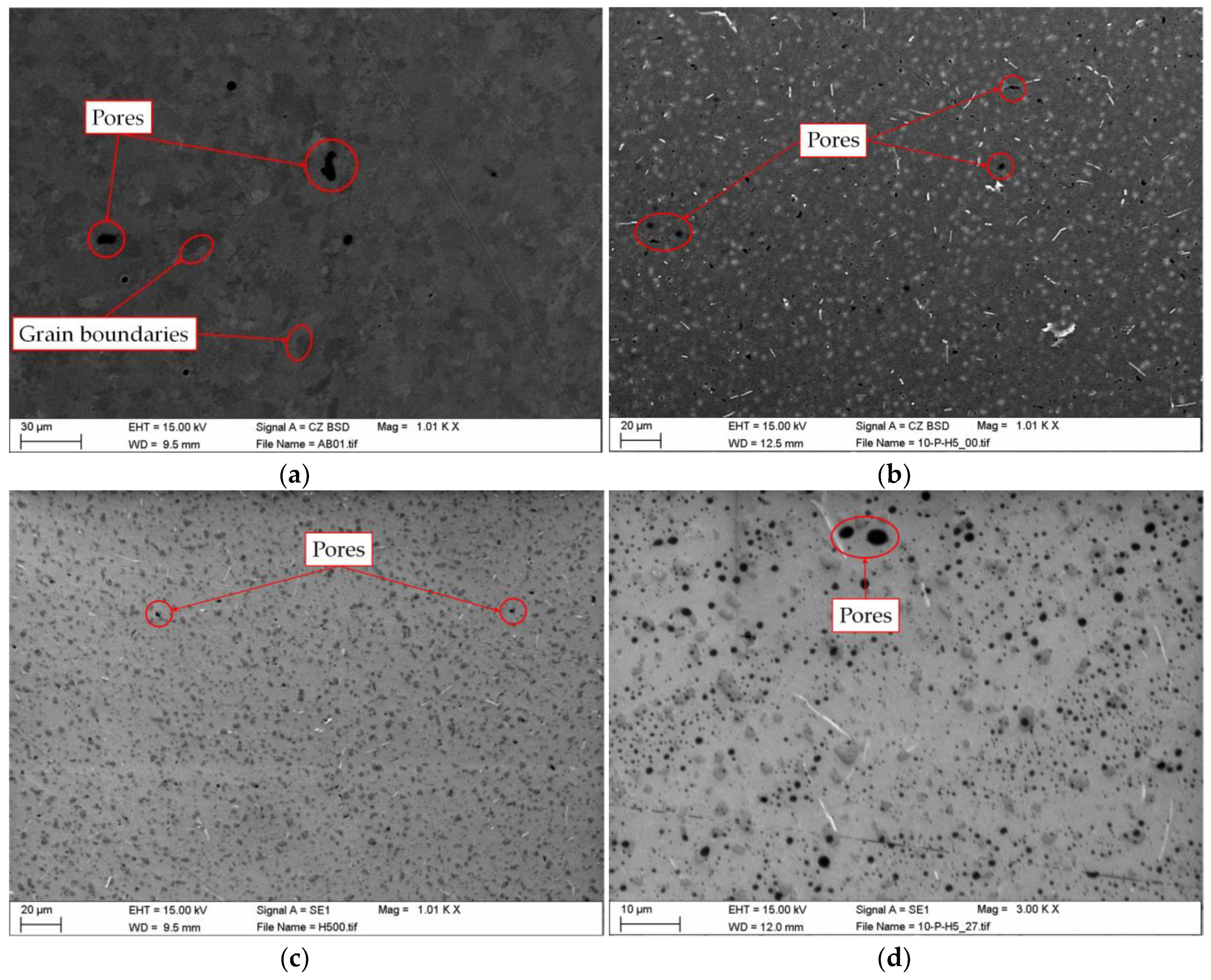
Comparing the microstructure of the as-built condition (
Figure 3a) to the microstructure after the post-treatment (
Figure 3b,c), appreciable differences regarding the porosity we observed. For that reason, these figures have the same magnification and scale. A larger magnification image is depictured in
Figure 3d, which reveals a circular shape of the observed micro-porosity. One can see that the amount of porosity and the maximum extension of pores have significantly decreased. Additionally, after the post-treatment, melt-pool boundaries completely vanished. The aforementioned Fe-rich precipitates and Si-crystals were formed within the microstructure. Throughout the annealing, the Si-particles grew at Si-rich cellular boundaries, and finally, grain boundaries were no longer clearly visible at this stage due to the heat influence [
23]. The comparison between backscatter images before (
Figure 3a) and after (
Figure 3b) HIP treatment highlights this microstructural change.
3.2. Fatigue Tests
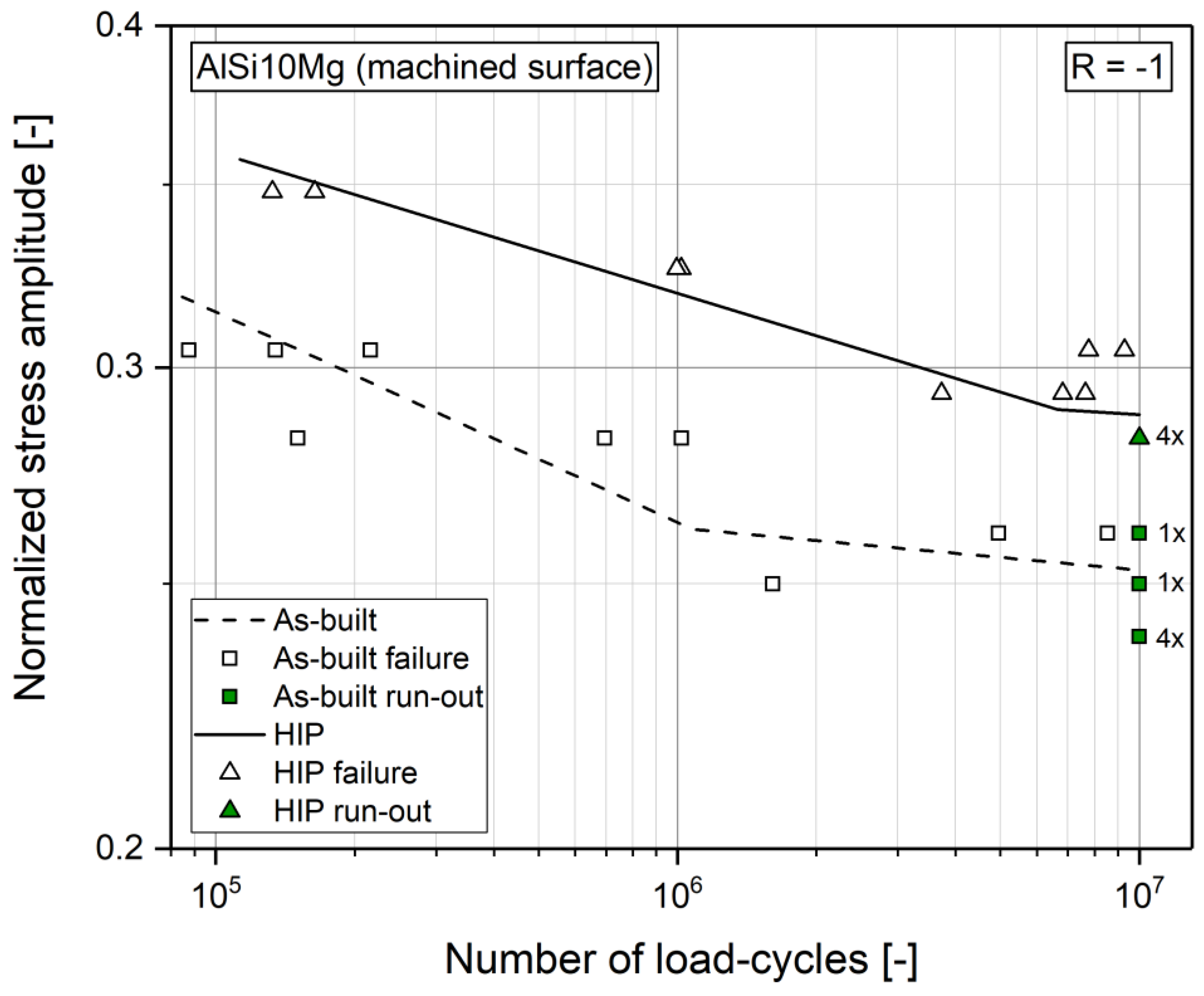
The fatigue test results are presented in
Figure 4. The dashed line with square marks represents the data for the as-built series. The full line with triangle markings shows the data for the HIP condition. Within the finite life region, the specimen was tested at several load levels with a certain incrementation. The evaluation of the SN-curve in the finite life region is based on the ASTM E739 standard [
27]. The high cycle fatigue strength at 1 × 10
7 load-cycles was statistically evaluated by applying the arcsin√P-transformation procedure given in [
28]. Run-outs were reinserted at higher stress levels in order to obtain additional data within the finite life region. The results were normalized to the nominal ultimate tensile strength (UTS) of the additively-manufactured material without any post-treatment, given by the powder manufacturer [
29]. The peak load level was set at about 35% of the UTS, which was well below the yield strength according to the powder manufacturer, to ensure testing within the linear-elastic region of the material and obtain reasonable results regarding endured load cycles. The results revealed that the HIP test series provided an increase of the high cycle fatigue strength of about 14% considering a survival probability of P
S = 50%. The scatter band between 10% and 90% survival probability, referring to the stress amplitude, minorly decreased for the HIP condition compared to the as-built condition. Furthermore, the slope in the finite life region was less steep for the HIP condition. The fatigue test results are summarized in
Table 2.
3.3. Metallographic and Fracture Surface Analysis
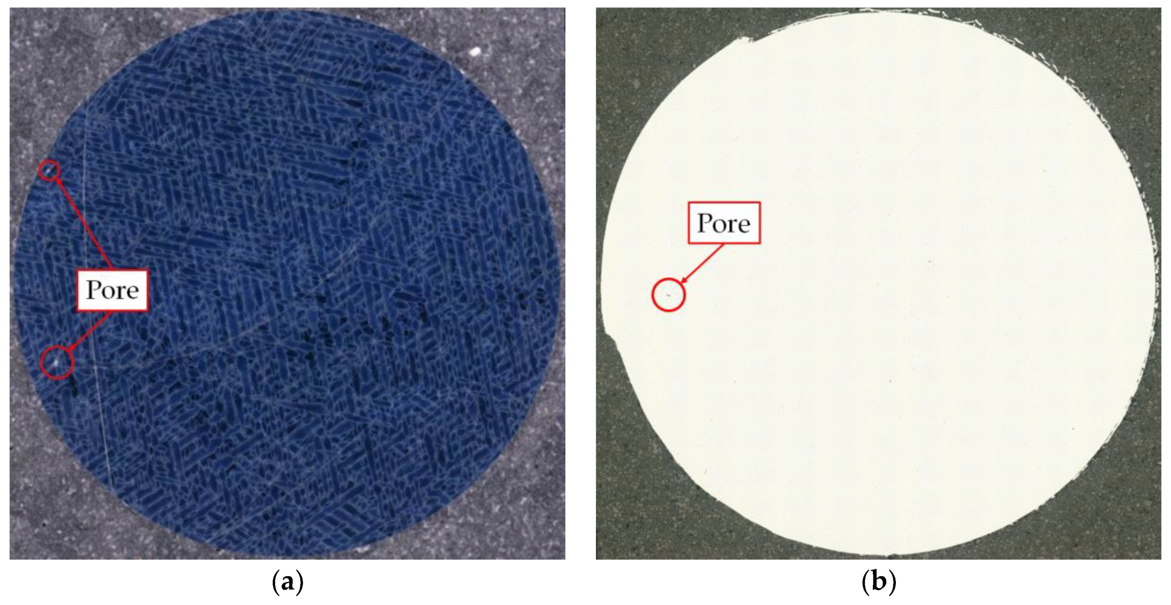
In order to evaluate the decrease in porosity, the average maximum pore extension, as well as the equivalent circle pore diameter, several micrographs of the two conditions were investigated.
Figure 5a shows an example of the as-built condition, whereas
Figure 5b is taken from the microsection of an HIP-treated specimen. All pictures of micrographs and fracture surfaces were recorded with a KEYENCE VHX-5000 light optical digital microscope. The microsections were prepared only by polishing and received no additional etching. Dependent on the polished surface and the image post-processing, different lighting options and angles were necessary. This was the reason why the as-built specimen in
Figure 5a (ring-lighting) appears blue and shows a different texture, e.g., visible melting tracks and laser scanning strategy, than the HIP sample in
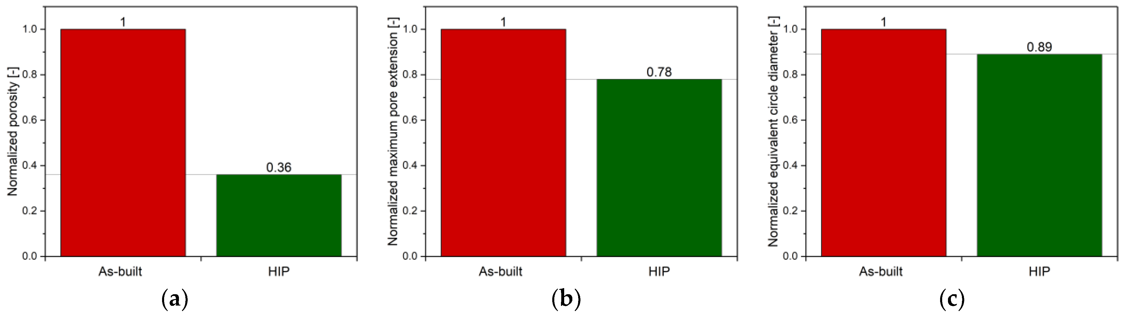
Figure 5b (coaxial lighting). In order to determine the amount of porosity, image processing tools were utilized. At first, the images were converted to binary pictures with a certain threshold to ensure that the microsection of the specimen area appeared white while pores appeared black. Secondly, the embedding material was subtracted from the image. In the end, the separated pores, as well as the porosity, which is the ratio of specimen area to pore area, could easily be evaluated. The outcome is presented in
Figure 6a–c and summarized in
Table 3. The results were again normalized to the as-built condition to highlight the differences between the two test series. The results maintained that the HIP samples possessed a significant lower level of porosity (−64%), a decreased maximum pore extension (−22%), as well as an equivalent circle diameter (−11%).
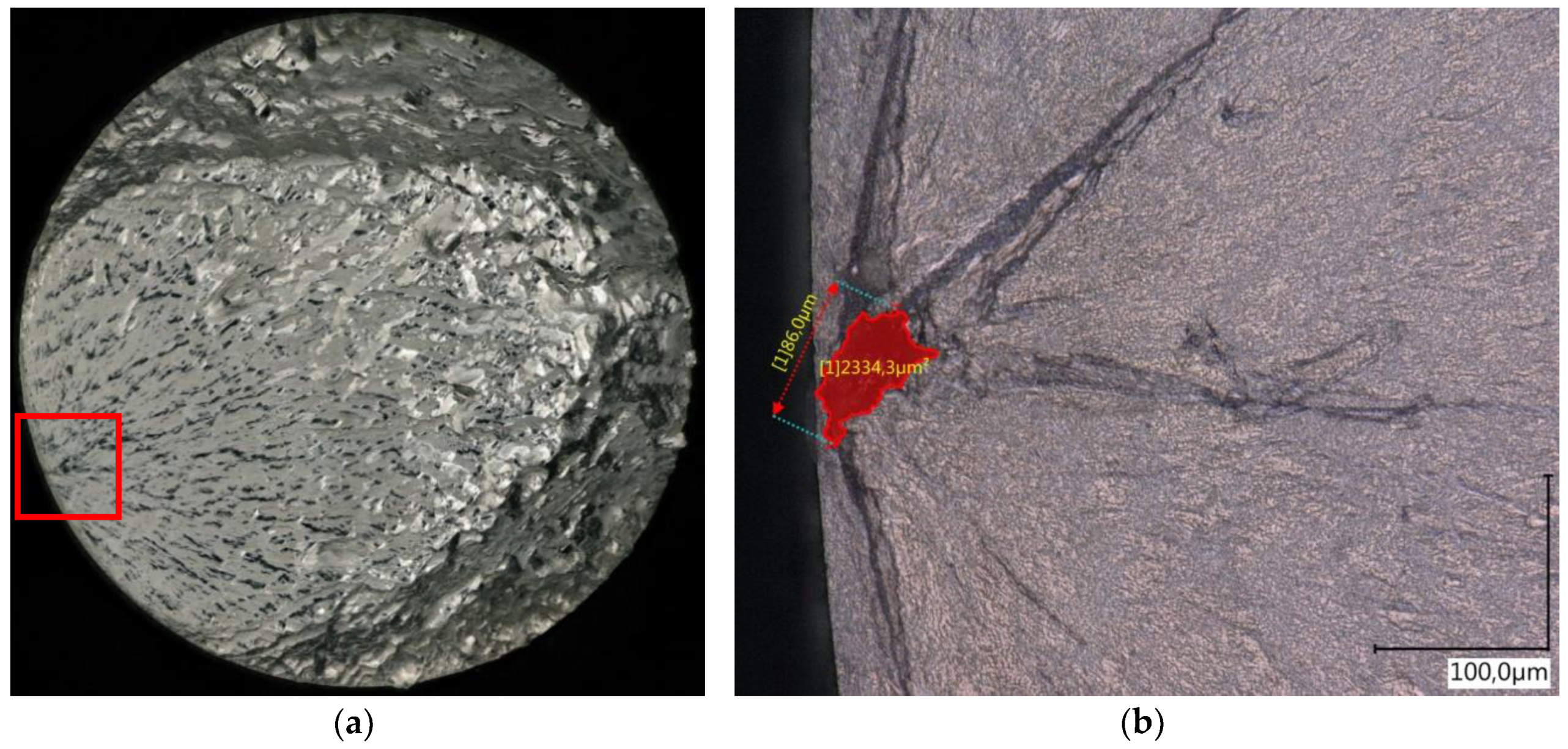
To characterize the crack-initiating defect, a fracture surface analysis for each tested specimen was carried out. A fractured surface of the as-built specimen is presented in
Figure 7a. The surface is visually differentiated into two sections, the oscillating crack growth regime and the burst fractured area. The defect, which was responsible for the failure, can be easily identified and evaluated. In every investigated fractured surface for the as-built condition, a pore was failure critical. An example with a marked and measured pore is given in
Figure 7b. The size and location of the failure causing imperfection was one determining factor for the fatigue strength of the material; see also [
30,
31]. Therefore, an evaluation of the defect size was necessary to compare and to assess the fatigue strength of the two investigated conditions.
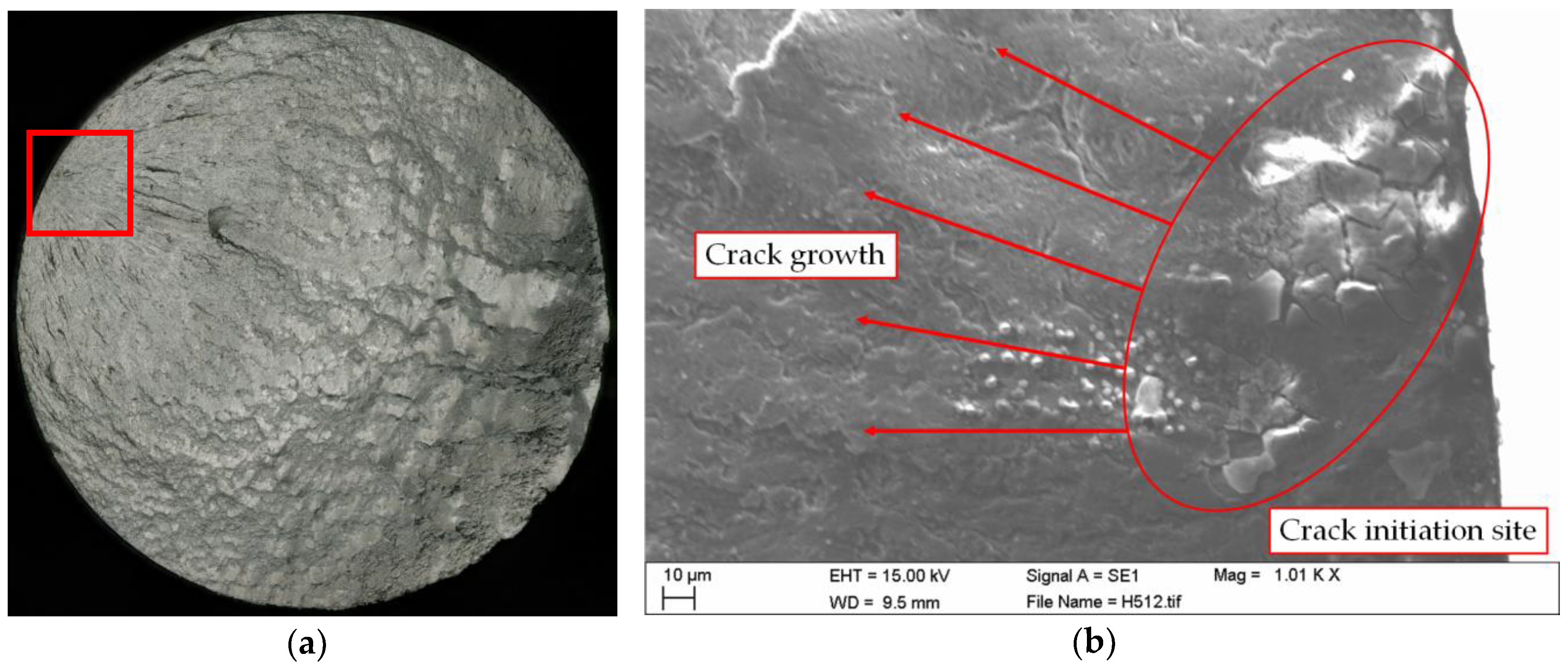
A fracture surface for the post-processed condition (two-dimensional image with in depth focus) is displayed in
Figure 8a. As pointed out for the as-built condition, the fracture surface is again separated into two different zones. The crack origin can be found within the fatigue fracture area, since the fine structured area points towards the crack initiation site. The fracture surface analysis for the HIP specimens revealed a different failure mechanism compared to the as-built ones. Due to the remarkable decrease in porosity, cavities were no longer responsible for fatigue crack initiation, but rather microstructural features such as silicon-rich phases. In
Figure 8b, one can identify the debonding of Si-crystals as the failure origin; see also [
26]. The crack initiated near the subsurface at all tested samples, for the HIP condition, as well as for the as-built condition. In almost every case, no evidence of pores could be found near the crack origin.
4. Conclusions
Based on the results presented in this paper, a beneficial effect on the fatigue strength of an HIP treatment above the solubility temperature with subsequent low temperature annealing can be observed for the additively-manufactured AlSi10Mg material. Concerning the microstructure, there was a significant decrease in porosity by 64%, maximum pore extension by 22%, and equivalent circle diameter by 11%. Because of the heat influence, melt-pool boundaries were dissolved, and grain boundaries were no longer visible due to the growth of Si-precipitates at the cellular boundaries.
After finishing the post-treatment, silicon agglomerations, as well as needle-shaped, iron-rich intermetallic phases were formed. These precipitates caused a deceleration of the crack growth due to the interference of the crack front at these microstructural features. Such a microstructure generally improves the resistance against fatigue crack growth since the propagation of the crack is obstructed. In summary, it was observed that the changes of the microstructure due to the application of the post-treatment contributed to an enhanced fatigue strength.
In addition, a change of the failure mechanism was also detected. For the as-built condition, pores were the decisive defect type. On the contrary, intermetallic inhomogeneities provoked the failure for the HIP condition. The crack initiation site is found in every case within the surface near region, independent of the failure mode. The combination of the microstructural changes consequently influenced the crack initiation, as well as the propagation behavior, leading to an improvement of 14% of the high cycle fatigue strength at a survival probability of 50% by the applied post-treatment.
Author Contributions
Conceptualization, W.S. and M.L.; methodology, W.S and M.L.; validation, W.S. and M.L.; formal analysis, W.S.; investigation, W.S. and S.S.; resources, W.S.; data curation, W.S. and S.S.; writing, original draft preparation, W.S.; writing, review and editing, W.S. and M.L.; visualization, W.S.; supervision, M.L.; project administration, M.L. and F.G.
Conflicts of Interest
The funders had no role in the design of the study; in the collection, analyses, or interpretation of data; in the writing of the manuscript; nor in the decision to publish the results.
References
- Harun, W.; Kamariah, M.; Muhamad, N.; Ghani, S.; Ahmad, F.; Mohamed, Z. A review of powder additive manufacturing processes for metallic biomaterials. Powder Technol. 2018, 327, 128–151. [Google Scholar] [CrossRef]
- Hedayati, R.; Hosseini-Toudeshky, H.; Sadighi, M.; Mohammadi-Aghdam, M.; Zadpoor, A.A. Computational prediction of the fatigue behavior of additively manufactured porous metallic biomaterials. Int. J. Fatigue 2016, 84, 67–79. [Google Scholar] [CrossRef]
- Huynh, L.; Rotella, J.; Sangid, M.D. Fatigue behavior of IN718 microtrusses produced via additive manufacturing. Mater. Des. 2016, 105, 278–289. [Google Scholar] [CrossRef]
- Leary, M.; Mazur, M.; Elambasseril, J.; McMillan, M.; Chirent, T.; Sun, Y.; Qian, M.; Easton, M.; Brandt, M. Selective laser melting (SLM) of AlSi12Mg lattice structures. Mater. Des. 2016, 98, 344–357. [Google Scholar] [CrossRef]
- Watson, J.K.; Taminger, K. A decision-support model for selecting additive manufacturing versus subtractive manufacturing based on energy consumption. J. Clean. Prod. 2018, 176, 1316–1322. [Google Scholar] [CrossRef]
- Herzog, D.; Seyda, V.; Wycisk, E.; Emmelmann, C. Additive manufacturing of metals. Acta Mater. 2016, 117, 371–392. [Google Scholar] [CrossRef]
- Campbell, G.; Lahey, R. A survey of serious aircraft accidents involving fatigue fracture. Int. J. Fatigue 1984, 6, 25–30. [Google Scholar] [CrossRef]
- Uzan, N.E.; Shneck, R.; Yeheskel, O.; Frage, N. Fatigue of AlSi10Mg specimens fabricated by additive manufacturing selective laser melting (AM-SLM). Mater. Sci. Eng. A 2017, 704, 229–237. [Google Scholar] [CrossRef]
- Aboulkhair, N.T.; Maskery, I.; Tuck, C.; Ashcroft, I.; Everitt, N.M. Improving the fatigue behaviour of a selectively laser melted aluminium alloy: Influence of heat treatment and surface quality. Mater. Des. 2016, 104, 174–182. [Google Scholar] [CrossRef]
- Domfang Ngnekou, J.N.; Nadot, Y.; Henaff, G.; Nicolai, J.; Kan, W.H.; Cairney, J.M.; Ridosz, L. Fatigue properties of AlSi10Mg produced by Additive Layer Manufacturing. Int. J. Fatigue 2019, 119, 160–172. [Google Scholar] [CrossRef]
- Buffiere, J.-Y. Fatigue Crack Initiation and Propagation from Defects in Metals: Is 3D Characterization Important? Procedia Struct. Integr. 2017, 7, 27–32. [Google Scholar] [CrossRef]
- Domfang Ngnekou, J.N.; Nadot, Y.; Henaff, G.; Nicolai, J.; Ridosz, L. Influence of defect size on the fatigue resistance of AlSi10Mg alloy elaborated by selective laser melting (SLM). Procedia Struct. Integr. 2017, 7, 75–83. [Google Scholar] [CrossRef]
- Ceschini, L.; Morri, A.; Sambogna, G. The effect of hot isostatic pressing on the fatigue behaviour of sand-cast A356-T6 and A204-T6 aluminum alloys. J. Mater. Process. Technol. 2008, 204, 231–238. [Google Scholar] [CrossRef]
- Lee, M.H.; Kim, J.J.; Kim, K.H.; Kim, N.J.; Lee, S.; Lee, E.W. Effects of HIPping on high-cycle fatigue properties of investment cast A356 aluminum alloys. Mater. Sci. Eng. A 2003, 340, 123–129. [Google Scholar] [CrossRef]
- Wang, Q.; Apelian, D.; Lados, D. Fatigue behavior of A356/357 aluminum cast alloys. Part II—Effect of microstructural constituents. J. Light Met. 2001, 1, 85–97. [Google Scholar] [CrossRef]
- Wang, Q.; Apelian, D.; Lados, D. Fatigue behavior of A356-T6 aluminum cast alloys. Part I. Effect of casting defects. J. Light Met. 2001, 1, 73–84. [Google Scholar] [CrossRef]
- Beretta, S.; Romano, S. A comparison of fatigue strength sensitivity to defects for materials manufactured by AM or traditional processes. Int. J. Fatigue 2017, 94, 178–191. [Google Scholar] [CrossRef]
- Brandl, E.; Heckenberger, U.; Holzinger, V.; Buchbinder, D. Additive manufactured AlSi10Mg samples using Selective Laser Melting (SLM): Microstructure, high cycle fatigue, and fracture behavior. Mater. Des. 2012, 34, 159–169. [Google Scholar] [CrossRef]
- European Committee for Standardization (CEN). Aluminium and Aluminium Alloys—Castings—Chemical Composition and Mechanical Properties; CEN: Brussels, Belgium, 2010. [Google Scholar]
- Gänser, H.-P.; Maierhofer, J.; Christiner, T. Statistical correction for reinserted runouts in fatigue testing. Int. J. Fatigue 2015, 80, 76–80. [Google Scholar] [CrossRef]
- Ngnekou, J.N.D.; Henaff, G.; Nadot, Y.; Nicolai, J.; Ridosz, L. Fatigue resistance of selectively laser melted aluminum alloy under T6 heat treatment. Procedia Eng. 2018, 213, 79–88. [Google Scholar] [CrossRef]
- Li, W.; Li, S.; Liu, J.; Zhang, A.; Zhou, Y.; Wei, Q.; Yan, C.; Shi, Y. Effect of heat treatment on AlSi10Mg alloy fabricated by selective laser melting: Microstructure evolution, mechanical properties and fracture mechanism. Mater. Sci. Eng. A 2016, 663, 116–125. [Google Scholar] [CrossRef]
- Prashanth, K.G.; Scudino, S.; Klauss, H.J.; Surreddi, K.B.; Löber, L.; Wang, Z.; Chaubey, A.K.; Kühn, U.; Eckert, J. Microstructure and mechanical properties of Al-12Si produced by selective laser melting: Effect of heat treatment. Mater. Sci. Eng. A 2014, 590, 153–160. [Google Scholar] [CrossRef]
- Takata, N.; Kodaira, H.; Sekizawa, K.; Suzuki, A.; Kobashi, M. Change in microstructure of selectively laser melted AlSi10Mg alloy with heat treatments. Mater. Sci. Eng. A 2017, 704, 218–228. [Google Scholar] [CrossRef]
- Zhang, C.; Zhu, H.; Liao, H.; Cheng, Y.; Hu, Z.; Zeng, X. Effect of heat treatments on fatigue property of selective laser melting AlSi10Mg. Int. J. Fatigue 2018, 116, 513–522. [Google Scholar] [CrossRef]
- Gall, K.; Yang, N.; Horstemeyer, M.; McDowell, D.L.; Fan, J. The debonding and fracture of Si particles during the fatigue of a cast Al-Si alloy. Met. Mat. Trans. A 1999, 30, 3079–3088. [Google Scholar] [CrossRef]
- ASTM International. Standard Practice for Statistical Analysis of Linear or Linearized Stress-Life (S-N) and Strain-Life (ε-N) Fatigue Data; ASTM International: West Conshohocken, PA, USA, 2015. [Google Scholar]
- Dengel, D. Die arc sin √P-Transformation—Ein einfaches Verfahren zur grafischen und rechnerischen Auswertung geplanter Wöhlerversuche. Mater. Werkst. 1975, 6, 253–261. [Google Scholar] [CrossRef]
- EOS GmbH-Electro Optical Systems. Data Sheet: EOS Aluminium AlSi10Mg. 2014. Available online: https://lightway-3d.de/download/LIGHTWAY_EOS_Aluminium_AlSi10Mg_de_Datenblatt.pdf (accessed on 11 December 2018).
- Masuo, H.; Tanaka, Y.; Morokoshi, S.; Yagura, H.; Uchida, T.; Yamamoto, Y.; Murakami, Y. Effects of Defects, Surface Roughness and HIP on Fatigue Strength of Ti-6Al-4V manufactured by Additive Manufacturing. Procedia Struct. Integr. 2017, 7, 19–26. [Google Scholar] [CrossRef]
- Romano, S.; Beretta, S.; Brandão, A.; Gumpinger, J.; Ghidini, T. HCF resistance of AlSi10Mg produced by SLM in relation to the presence of defects. Procedia Struct. Integr. 2017, 7, 101–108. [Google Scholar] [CrossRef]
© 2019 by the authors. Licensee MDPI, Basel, Switzerland. This article is an open access article distributed under the terms and conditions of the Creative Commons Attribution (CC BY) license (http://creativecommons.org/licenses/by/4.0/).

 ,
, 


