Article

In Situ Fabrication of Metal Matrix Composite Using Solid-State Mechanical Mixing

1
Indian Institute of Science, Bengaluru 560012, India
2
Arbegast Materials Processing and Joining Laboratory (AMP), South Dakota School of Mines & Technology, Rapid City, SD 57701, USA
J. Manuf. Mater. Process. 2026, 10(3), 100; https://doi.org/10.3390/jmmp10030100
Submission received: 3 January 2026 / Revised: 10 March 2026 / Accepted: 13 March 2026 / Published: 16 March 2026

Abstract

Friction stir-welding (FSW) is widely recognized as a modern solid-state technology used to join dissimilar materials by solid-state mechanical mixing. Such mechanical mixing can be exploited to fabricate in situ composite structures through solid-state deformation mechanisms. The present investigation highlights the microstructural evolution and mechanical properties of an in situ composite structure fabricated by FSW of aluminum (Al) to titanium (Ti) incorporating a thin Nickel (Ni) interlayer. A 0.1 mm thick Ni foil was placed across the full butt interface between 4 mm thick Al and Ti plates before friction stir-welding. Properties of the composite were investigated in detail, and the results revealed that fragmented Ti and Ni particles of different sizes were consolidated in the weld nugget. Al, on the other hand, exhibited substantial microstructural refinement and developed an equiaxed microstructure with random grain orientation, mixed grain boundaries and low micro-strain accumulation in the weld nugget. At the processing temperature, Al reacted with both Ti and Ni to form multiple intermetallic compounds. Tensile testing indicated that the tensile properties of the weld were close to those of the base aluminum. This retention of mechanical properties in spite of recrystallization is attributed to the following mechanisms: (1) Ti and Ni undergo severe deformation, forming fine particles with varying sizes and shapes; (2) at particle interfaces, diffusion and chemical reactions produce interlayers and intermetallic compounds; (3) these particles are consolidated within dynamically recrystallized Al, imparting composite characteristics to the weld nugget; and (4) the particles containing intermetallic compounds act as dispersoids in the Al matrix. Quantitatively, the weld retained 98% (104.2 ± 3.3 MPa) UTS and 90% (17.1 ± 1.2) ductility of base aluminum, demonstrating the effectiveness of the Ni interlayer approach in controlling brittle intermetallic formation.

1. Introduction

The demand for composite and complex materials with gradient and locally enhanced properties in the transportation industry, including aerospace and motor vehicles, has increased in recent years [1]. Meeting these demands requires developing an adequate fabrication process for this composite structure. Fabrication of complex structures with composition and mechanical property variation is technically challenging, particularly for in situ synthesis. Joining dissimilar materials could be a feasible option to make such composite structures. However, this approach requires a suitable joining process for similar and dissimilar materials, which provides higher mechanical properties while controlling composite structure evolution in the weld nugget. Modern aerospace structures demand materials and joining processes that simultaneously minimize weight and maximize fuel efficiency and damage tolerance. Aluminum–titanium hybrid structures offer an ideal combination. For example, Fuselage assembly concepts currently employ mechanical fasteners; the welding of skin-stringer joints is foreseen to replace riveted fuselage structures [2]. FSW has demonstrated viability in secondary structural applications, such as seat–rail assemblies, positioning it as a candidate for primary-structure joining if mechanical properties can be optimized [3]. In this regard, the fabrication of a complex structure by welding titanium (Ti) to aluminum (Al) has significant applications in aerospace structures, as Al offers a high strength-to-weight ratio, low density, and good formability, whereas Ti provides excellent specific strength, corrosion resistance, and high-temperature capability. In this context, reliable welding or in situ fabrication of Al–Ti hybrid structures is of significant technological interest.
Fusion welding of commercially available Al to Ti is challenging due to differences in their physical and thermal properties and the formation of brittle intermetallic phases, which degrade weld properties. The nucleation and growth of such intermetallic layers are controlled by a combination of process parameters, alloying elements, temperature, and time [4,5]. Solid-state welding methods, such as diffusion bonding [5], friction welding [4,6], roll bonding, and ultrasonic welding [7], have been employed to join these two materials with the purpose of controlling the evolution of brittle intermetallics.
Although solid-state joining processes (diffusion bonding, friction welding, FSW) reduce intermetallic layer thickness relative to fusion welding, dissimilar Al–Ti joining still produces continuous, thermodynamically favored Al3Ti layers at the bond line, limiting mechanical efficiency and ductility. FSW, with its localized heating and intense mechanical stirring, offers a distinct mechanism to fragment and redistribute reaction products rather than permitting the formation of monolithic brittle layers [8,9]. Beyond simply suppressing intermetallics, FSW offers the possibility of using process-controlled mechanical mixing to generate in situ metal matrix composites, in which fragmented reinforcement particles and intermetallics are dispersed within a refined matrix. The incorporation of intermediate material could be a feasible solution for joining dissimilar materials. It could modify the type, morphology, and continuity of intermetallic phases formed at the Al–Ti interface, thereby improving the mechanical properties of the joint.
Despite extensive work on dissimilar Al–Ti joining by fusion and solid-state routes, most studies focus on suppressing and/or thinning the Al–Ti intermetallic layer at the weld interface rather than deliberately exploiting controlled mechanical mixing to create an in situ composite in the weld region. Interlayers such as Cu, Zn, and Ni have been used in other dissimilar systems to tailor interfacial reactions. However, systematic understanding and characterization of how a Ni interlayer can simultaneously influence intermetallic phase evolution, particle dispersion, and matrix microstructure evolution, such as recrystallization, in Al–Ti FSW joints remain limited. This constitutes a key research gap for the rational design of dissimilar Al–Ti joints with both high strength and high ductility
The objective of the present investigation is to examine the metallurgical and mechanical properties of the weld between Al and Ti with Ni interlayer using FSW. The study also demonstrates that this configuration can be used to fabricate an in situ metal matrix composite within the weld nugget. More specifically, the study aims to establish a mechanistic link between process-induced mechanical mixing, phase formation, and tensile behavior in friction stir-welded Al/Ti joints incorporating a Ni interlayer.
The microstructure of the weld was characterized to (i) characterize the three-dimensional distribution and morphology of Ti- and Ni-containing particles in the weld nugget using X-ray computed tomography, (ii) elucidate the intermetallic phase assemblage and its evolution through X-ray diffraction and SEM/EDS, (iii) quantify grain refinement, grain boundary character, and texture development in the Al matrix via EBSD, and (iv) relate these microstructural features to the tensile strength and ductility of the weld region. The investigation aims to demonstrate how controlled solid-state mechanical mixing during FSW can be exploited to generate an in situ composite with tensile properties comparable to those of the base Al material.

2. Experimental Procedure

2.1. Materials and Ni Interlayer Preparation

Commercially available rolled plates of commercially pure aluminum (cp-Al) and commercially pure titanium (cp-Ti), each 4 mm thick, were used as the starting materials. The chemical composition of these materials is presented in Table 1. A commercially pure Ni foil used in the current study consisted of a cold-rolled Ni foil with a nominal purity of ≥99.5 wt.% Ni. The foil thickness was 1.08 ± 0.22 mm, which was measured at five random locations per coupon using calibrated digital micrometry. The Ni foil was used as an interlayer at the Al/Ti interface, as shown in Figure 1. The Al and Ti plates were 4 mm thick, 100 mm long, and 50 mm wide, and the Ni foil extended across the full lap area between the plates. Prior to welding, all plates and foils were cut to size, degreased in acetone, and mechanically abraded with SiC papers up to 1200 grit to remove surface oxides and contaminants. The samples were then rinsed with ethanol and dried in warm air, and the joint assembly was completed within 30 min of surface preparation to minimize re-oxidation.

2.2. Friction Stir-Welding Setup

To prevent relative motion during tool plunge and traversing, the plates and interlayer were clamped using a rigid backing plate and mechanical clamps along the plate edges, as schematically shown in Figure 1. This arrangement ensured intimate contact and helped eliminate any gaps at the interface. The plates were joined by FSW in a butt-joint configuration using a custom-built five-axis FSW machine developed jointly by the Indian Institute of Science (IISc), Bangalore, India, and Bangalore Integrated System Solutions (P) Ltd., Bangalore, India. Base Al and Ti were clamped on the Advancing Side (AS) and Retreating Side (RS) of the welding process, respectively. A cylindrical tool made of tungsten alloy (WC-8%Co) with a shoulder diameter of 20 mm was used for welding. The length and diameter of the tool pin were 3.5 mm and 4.0 mm, respectively. During FSW, the tool rotation speed was 800 rpm, with a traverse speed of 40 mm/min and plunge depth of 3.8 mm. During welding, the tool was offset by 2.0 mm toward the Al side from the weld interface in order to promote more intense deformation on the Al side.

2.3. Microstructural Characterization

To examine the microstructure of the weld, transverse cross-sections were sectioned from the weld by wire-electrical discharge machining (WEDM), perpendicular to the welding direction. The samples were prepared using standard metallographic procedure, including grinding and polishing, followed by selective etching with Kroll’s reagent for Ti and Keller’s reagent for Al to reveal grain structure and phase morphology. The polished and etched samples were examined using an optical microscope (OM) and a Scanning Electron Microscope (SEM) equipped with an Energy Dispersive Spectrometer (EDS). The OM was used to characterize macro- and microstructural features across the weld cross-section. SEM with EDS was used to perform detailed microstructural and compositional analyses.
To assess finer details of the Al matrix, such as grain size, grain boundary character, and local misorientation, electron backscatter diffraction (EBSD) measurements were performed. For this study, the sample was separately electro-polished using Struers Lectropol-5 electropolisher (Struers A/S, Ballerup, Denmark). Standard A3 and A2 electrolytes were used for Ti and Al, respectively, for final polishing. The electropolishing conditions were 36 V for 10 s for Ti and 26 V for 20 s for Al. EBSD scans were acquired using a TSL (TexSEM Laboratories, EDAX, Mahwah, NJ, USA) data acquisition system attached to the same tungsten-filament SEM, and the data were analyzed with TSL-OIM version 7.1 software. For EBSD of the Al matrix, the SEM was operated at an accelerating voltage of 20 kV with a working distance of 15 mm, using a step size of 0.5 µm for both as-received Al and weld-nugget center to adequately resolve the refined grains. Scan areas of approximately 118 × 88 μm2 (base Al) and 84 × 68 µm2 (weld nugget) were selected to obtain statistically meaningful grain populations. Raw EBSD data were cleaned by applying a confidence-index (CI) filter, setting a CI threshold of 0.5 to remove poorly indexed points and second-phase particles (Ti, Ni, and intermetallics), followed by standard nearest-neighbor dilation/erosion to fill isolated non-indexed pixels. Grain boundaries were reconstructed using a minimum misorientation angle of 15° for high-angle grain boundaries (HAGBs), 5–15° for low-angle grain boundaries (LAGBs), and <5° for sub-grain boundaries, with a minimum grain size of three to four pixels to avoid spurious grains. Grain size was calculated as the equivalent circle diameter of each reconstructed grain, while local misorientation was quantified using kernel average misorientation (KAM) with a first-neighbor kernel. Grain orientation spread (GOS) was used to distinguish approximately strain-free grains (GOS ≤ 2°) from moderately and heavily deformed grains [10].

2.4. X-Ray Diffraction

The phases formed in the weld zone and Al/Ti interfaces were identified by X-ray diffraction (XRD). The weld interface was positioned at the center of the irradiated area during measurements. Diffraction patterns were recorded with a 2θ angle range between 30° and 90° using Cu Kα radiation, with a wavelength of 1.54056 Å, using a Philips (X’Pert PRO PANalytical) X-ray diffractometer, which was operating at 40 kV and 30 mA. A manual program was used to perform a scan with a step size of 0.033° and a scan rate of 0.008°/s. The data obtained from XRD measurement were analyzed using the X’Pert Highscore PANalytical software 6.x to identify intermetallic compounds, and the results are presented and discussed in subsequent sections.

2.5. X-Ray Computed Tomography (XCT)

Three-dimensional non-destructive characterization of the weld nugget was carried out using X-ray computed tomography (XCT) on a Zeiss Versa 520 system. In the present work, XCT was employed primarily as a qualitative tool to visualize the three-dimensional distribution and morphology of Ti- and Ni-containing particles in the weld nugget. The reconstructed volumes were inspected to identify particle locations, shapes, and clustering behavior, but no absolute calibration of the segmented volume fraction or particle size distribution was attempted; the analysis is therefore limited to qualitative interpretation. During the measurement, the samples were mounted on a rotating turntable positioned between the X-ray source and detector, and a series of radiographs were acquired over a defined rotation range (0–180°) with a step size of 5°. Total time for scanning was approximately 6 h. The radiographs were then used to reconstruct the final 3D volume of the weld nugget. Reconstruction of the 3D volume enabled segmentation of Ti- and Ni-containing regions using user-defined gray-level thresholds, thereby revealing the spatial distribution of these phases within the Al matrix. Analysis was explicitly limited to a visual inspection of reconstructed volumes.

2.6. Tensile Testing Procedure

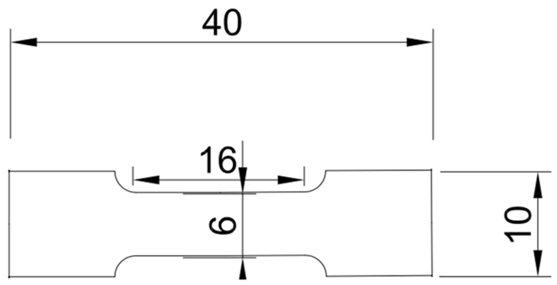
Bulk tensile tests were performed on specimens extracted from both the as-received Al plate and the weld region in order to evaluate the effect of FSW and the Ni interlayer on mechanical properties as per the ASTM E8 standard. Tensile testing of the specimens was carried out using an Instron 8032 servo-hydraulic universal testing machine (UTM) that has a maximum load capacity of 100 kN. A nominal initial strain rate of 10−3/s was used during testing. Tensile test samples were cut from the weld plate, perpendicular to the weld direction, with dimensions as shown in Figure 2, ensuring that the weld nugget was located within the gauge section for weld samples. At least three tests were carried out for each condition, and representative engineering stress–strain curves and average properties are reported.

3. Results and Discussion

3.1. Weld Macrostructure and Defect Analysis

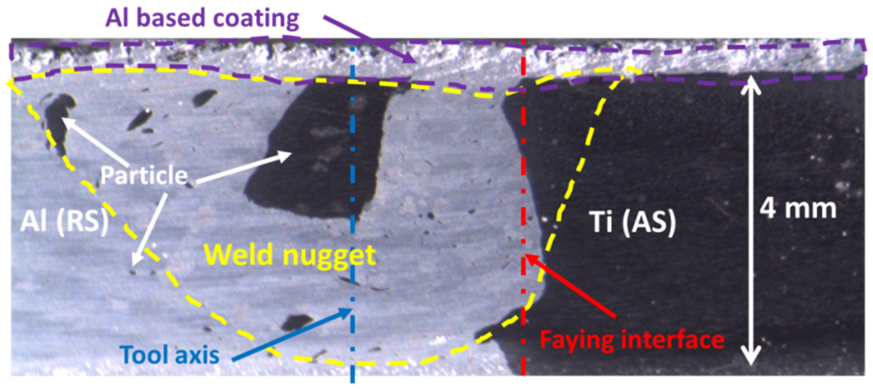
Macrostructure of the weld is shown in Figure 3. The tool axis is deliberately offset from the original faying interface by approximately 2 mm towards the Al side from the original Al/Ti interface. Therefore, deformation primarily concentrates on the Al side, which helps save the tool due to the reduced direct interface interaction between the high-strength Ti (positioned on AS of the weld) and the tool [11]. The weld does not contain defects, such as voids and cracks. This indicates that the selected process parameters are adequate to ensure sound consolidation. The weld contains a number of Ti particles with varying particle sizes. A relatively large Ti particle is observed near the center of the nugget.
As schematically shown in Figure 3, the weld nugget exhibits a larger width at the top surface compared to the bottom. This is attributed to the larger contact area between the tool shoulder and the workpiece, which generates higher heat input and more intense plastic deformation in the upper region relative to the region influenced solely by the tool pin. Consequently, Al in the upper nugget experiences severe softening from shoulder-driven heat input [12]. This generates a continuous surface coating, as highlighted in Figure 3 (indicated by violet arrow and circle) [13]. Such heat input elevates local temperatures to approximately 0.85–0.95 Tm (Tm = melting point of aluminum, which is 660 °C) based on experimental measurement and heat generation models [14,15,16]. The coating prevents direct contact between Ti and the underlying tool, reducing frictional heating and the resulting peak temperature in the weld zone. This coating also influences the fragmentation and transport of Ti during stirring.

3.2. Three-Dimensional Particle Distribution

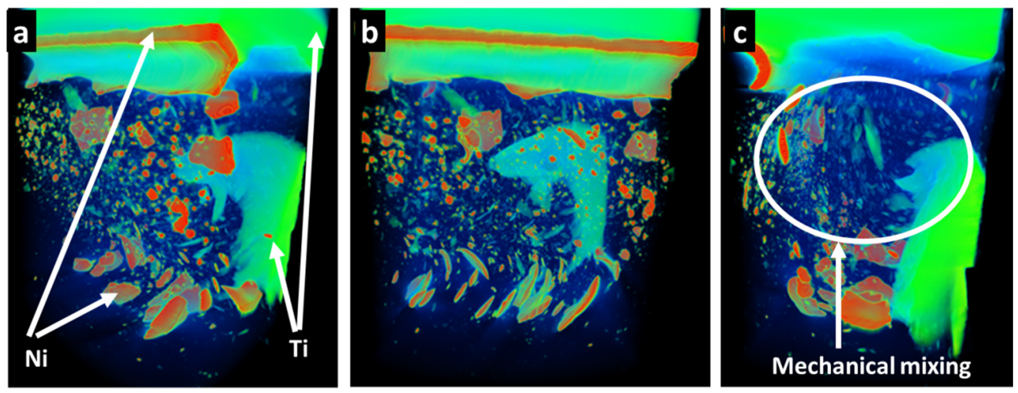
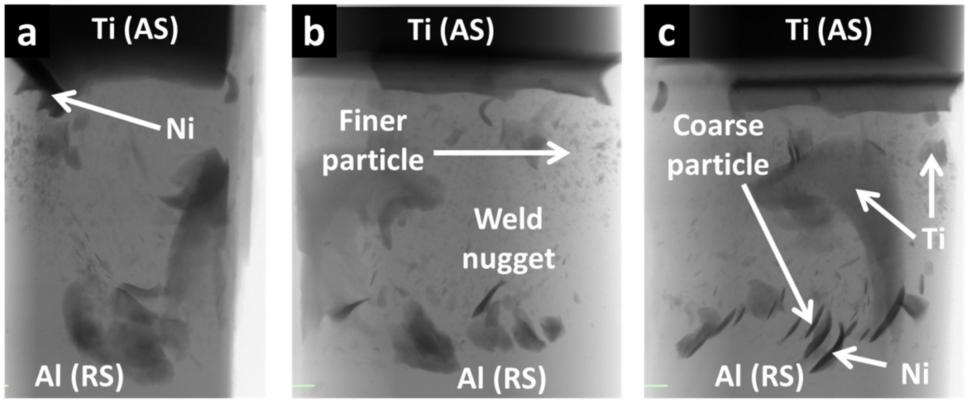
XCT was employed strictly as a qualitative tool to visualize Ti/Ni particle morphology, locations, and clustering behavior. Since Ti, Ni, and Al have different X-ray absorption levels, XCT was used to examine the three-dimensional distribution of Ti and Ni within the weld nugget. By selecting a user-defined gray-level threshold corresponding to Ti and Ni, it is possible to visualize these phases while effectively suppressing the Al matrix in the reconstructed volume. The threshold range corresponding to Al was not selected during analysis; therefore, Al is not visible in the image. Figure 4 and Figure 5 show a 3D isometric view of such an XCT image. The front and side views of Figure 4a, as seen from the bottom of the weld, are shown in Figure 4b and Figure 4c, respectively. From these images, it can be seen that Ti and Ni particles of different shapes and sizes are distributed in the weld nugget in a distinctly inhomogeneous manner. A mechanically mixed zone (MMZ) is evident near the original joining interface, close to the center of the nugget (encircled in Figure 4c). This zone forms due to severe plastic deformation and intense mechanical stirring induced by the rotating tool, which fragments the Ti-Ni interlayer and intermingles it with the Al matrix. Local variations in composition at the particle/matrix interfaces are expected to influence the nucleation and growth of intermetallic phases, thereby affecting the final microstructural and mechanical properties of the joint. It is also seen that no large particle-free regions are present in the examined volume (Figure 5a–c). Although the present XCT analysis is qualitative and does not provide absolute volume fractions or particle size statistics, the three-dimensional visualizations clearly demonstrate that fragmented Ti and Ni are dispersed throughout the nugget and participate in mechanical mixing near the original Al/Ti interface (Figure 5b,c). This qualitative 3D evidence supports the interpretation that the weld nugget behaves as an in situ composite, with a population of reinforcing particles embedded in the Al matrix that can influence load transfer and crack-propagation paths during mechanical loading.
At this stage, the XCT analysis was restricted to qualitative assessment of particle dispersion. Segmented volumes were visually inspected to understand the three-dimensional morphology and connectivity of Ti- and Ni-containing regions, but systematic quantitative metrics, such as volume fraction, particle size distribution, or spatial statistics, were not extracted. Future work will focus on calibrated segmentation and quantitative stereology to provide a more rigorous statistical description of the in situ composite microstructure.

3.3. Phase Identification and Intermetallic Formation

3.3.1. X-Ray Diffraction Analysis

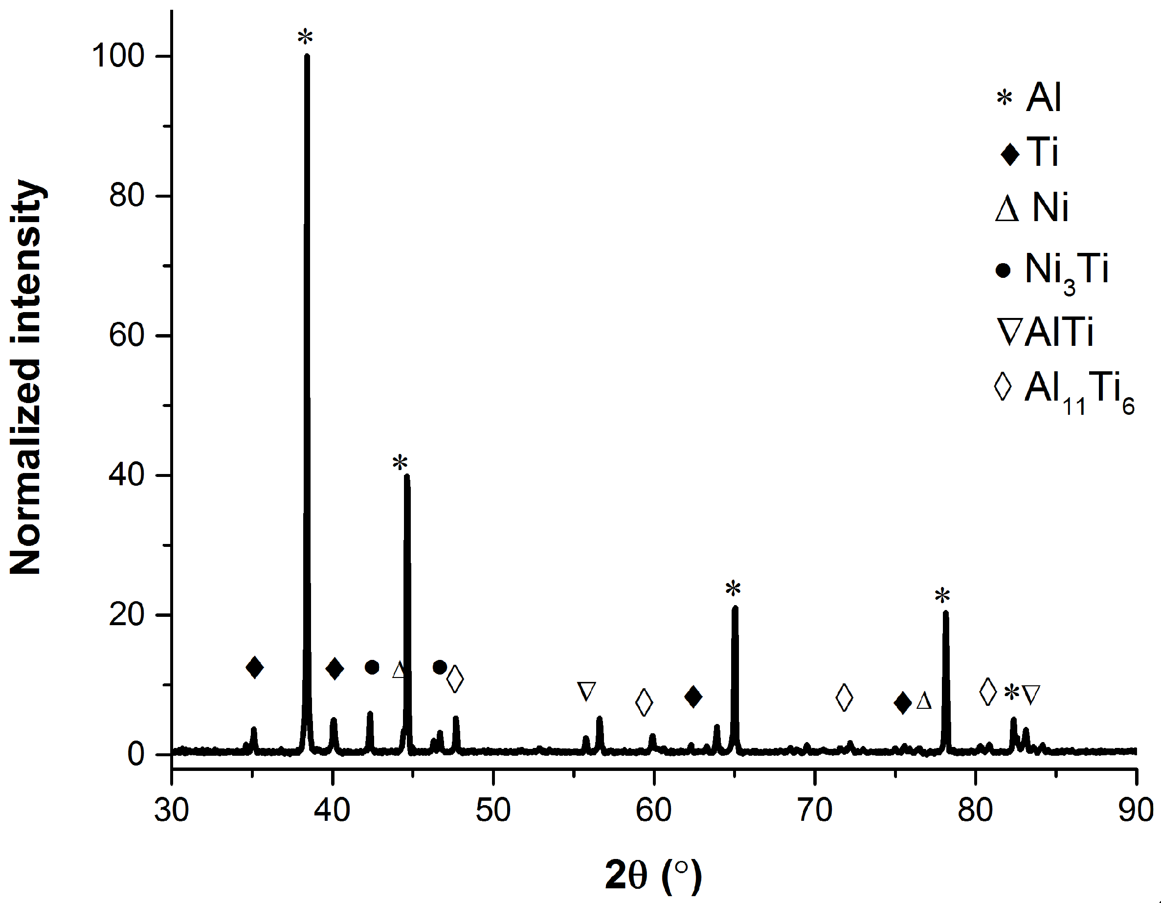
To identify phase evolution in the weld zone, XRD measurements were performed with the weld interface at the center of the irradiated area. The diffraction patterns obtained from the weld sample are shown in Figure 6. The patterns indicate the presence of a number of intermetallic compounds, namely Ni3Al, AlTi, and Al11Ti6, within the weld nugget.
It can be seen that characteristic reflections of Al3Ti were not detected under the present bulk XRD measurement conditions, which suggests that the formation of this phase is significantly suppressed and/or limited to a volume fraction below the detection limit of the technique. This observation indicates that the Ni interlayer modifies the local chemical environment and reaction pathway at the Al–Ti interface, favoring the formation of Ni3Al-, AlTi-, and Al11Ti6-type intermetallics, instead of a continuous Al3Ti layer that is typically associated with brittle behavior in Al–Ti joints. The absence of Al3Ti can be attributed to Ni-rich interfacial zones and mechanically mixed zones that locally suppress the Al:Ti atomic ratio below the threshold required for Al3Ti formation. Thermodynamic calculation indicates that Ni3Al (ΔG_f ≈ −35.55 kJ/mol) and AlTi (ΔG_f ≈ −29.05 kJ/mol) possess lower Gibbs free energies than Al3Ti (ΔG_f ≈ −35.17 kJ/mol at 500 K) when Ni co-exists [17,18]. Thus, the Ni interlayer functions as a thermodynamic–kinetic bifurcation agent: by reducing local Al:Ti stoichiometry during interlayer dissolution, the interface chemistry shifts away from the Al3Ti stability field toward the Ni-Al-Ti ternary field where Ni-based phases are thermodynamically favored. Therefore, the Ni interlayer appears to modify reaction pathways.
However, the absence of Al3Ti peaks in the XRD patterns does not strictly prove that Al3Ti is completely absent. Instead, it suggests that any Al3Ti present is below the detection threshold or restricted to areas that contribute insignificantly to the measured volume. It is important to note that the XRD configuration used here has limited penetration depth and detection limit; therefore, phases present in extremely small amounts or confined to narrow interfacial areas may not be detected in the diffraction patterns. This reduction in continuous brittle Al3Ti layers is expected to decrease the overall brittleness of the joint and enhance its load-bearing capability. This is because of the morphology and distribution of newly formed Ni3Al, AlTi, and Al11Ti6 intermetallics. The replacement of a continuous Al3Ti layer by discrete, finely dispersed Ni-containing and Al–Ti intermetallics in a refined Al matrix reduces the effective brittleness of the joint, even though the individual phases themselves are not fully ductile. This is supported by elemental analysis and a ductile fracture surface in the weld nugget, which will be discussed later.

3.3.2. SEM-EDS-Based Chemical Analysis

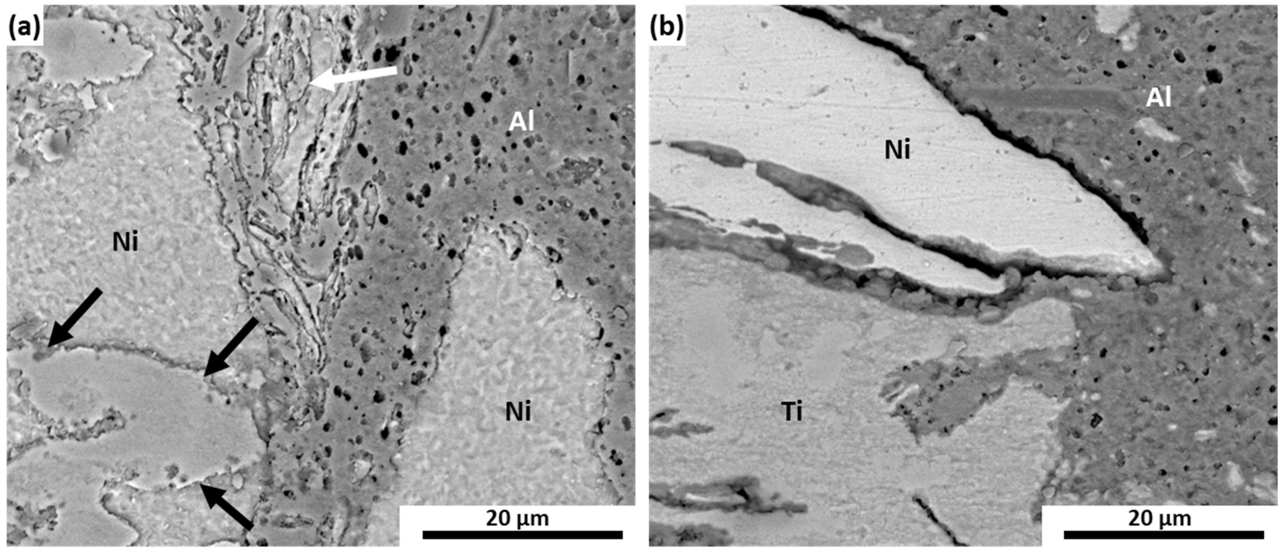
To complement the bulk XRD results and strengthen phase identification, local microstructural analysis was performed using SEM in backscattered-electron (BSE) mode, combined with EDS mapping, in the weld nugget and at the weld interface. Figure 7a shows a BSE image from the weld nugget, revealing intense mechanical mixing and the distribution of Al, Ti, and Ni. Severely deformed and fragmented Ti particles, indicated by white arrows, are in direct contact with Ni-rich regions, while other less-deformed Ti particles interacting with Ni are marked by black arrows. These observations demonstrate that Ni and Ti undergo local chemical interaction within the nugget, which reduces the effective area available for direct Al–Ti contact and thereby diminishes the likelihood of forming continuous brittle Al3Ti intermetallic layers. In support of this interpretation, Figure 7b presents another nugget-zone region where an extended Ni/Ti interface is observed, again indicating that Ni occupies and stabilizes interfaces that would otherwise be dominated by Al–Ti reaction.
An EDS elemental map acquired from the weld interface is shown in Figure 8. The overall weld interface is presented in Figure 8a, and a high-magnification view of the interfacial zone (marked by the square in Figure 8a) is shown in Figure 8b. EDS maps of this region (Figure 8c–f) reveal that very fine Ni-containing particles are dispersed throughout the mechanically mixed zone between the Al matrix and the Ti side of the interface. The superimposed elemental map, together with the individual Al, Ni, and Ti maps, confirms that this zone has a modified local composition in which Ni is distributed within the Al–Ti transition region, thereby reducing the extent of direct Al/Ti interaction and suppressing the formation of Al3Ti-type intermetallics. Instead, the local chemistry in this zone is consistent with the preferential formation of Ni-containing intermetallics, in agreement with the Ni3Al- and AlTi-type phases detected by XRD. Taken together, these observations from the nugget and interface regions demonstrate that Ni participates actively in interfacial reactions with Ti and redistributes within the mechanically mixed zone, which promotes Ni-based intermetallic formation and mitigates the development of continuous brittle Al3Ti.
Variation in chemical composition and phase assemblage within the weld nugget and at the interface is important for the joint’s mechanical properties. However, mechanical properties are not solely determined by the interfacial phases but also depend strongly on the microstructure of the Al matrix, which constitutes the primary load-carrying phase in the weld nugget. Therefore, the Al matrix was characterized in detail, and the mechanism of microstructural evolution was investigated to correlate with mechanical properties.

3.4. Mechanism of Microstructure Evolution of Al Matrix

In addition to controlling the distribution of Ti and Ni particles and the evolution of intermetallic compounds, the microstructural evolution of Al in the weld nugget plays a dominant role in determining the mechanical properties of the joint. EBSD analysis of both the base Al and the weld-nugget-center regions was therefore conducted to compare and understand the mechanism of microstructural evolution during welding.
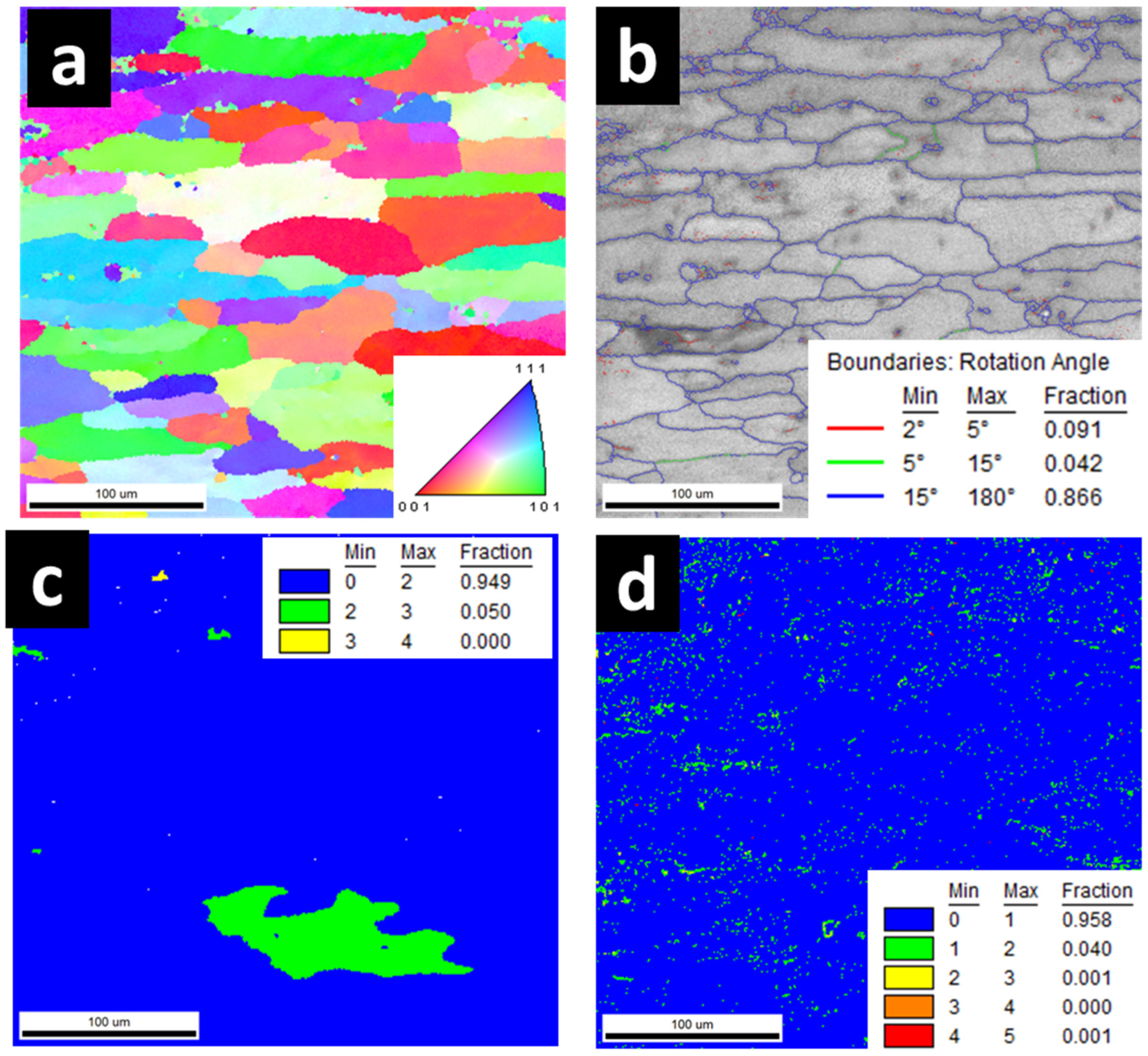
Figure 9a–d shows the inverse pole figure (IPF) map, the grain boundary character distribution (GBCD) map, the grain orientation spread (GOS) map, and the kernel average map (KAM) for the as-received Al, respectively. The IPF map (Figure 9a) reveals predominantly elongated grains exhibiting random crystallographic orientations, with a measured average grain size of 40.2 ± 18.4 μm. Figure 9b illustrates the GBCD map, which distinguishes three types of boundary populations. They are sub-grains (0° ≤ θ ≤ 5°), low-angle grain boundary (LAGB; 5° ≤ θ ≤ 15°), and high-angle grain boundary (HAGB; θ ≥ 15°). Approximately 87% of boundaries are HAGBs, distributed uniformly throughout the as-rolled microstructure. The GOS (Figure 9c) and KAM (Figure 9d) maps show that approximately 95% of the grains exhibit low GOS values (GOS ≤ 2°) and correspondingly low local misorientation, indicating a relatively low dislocation density in the as-received Al (Table 2).
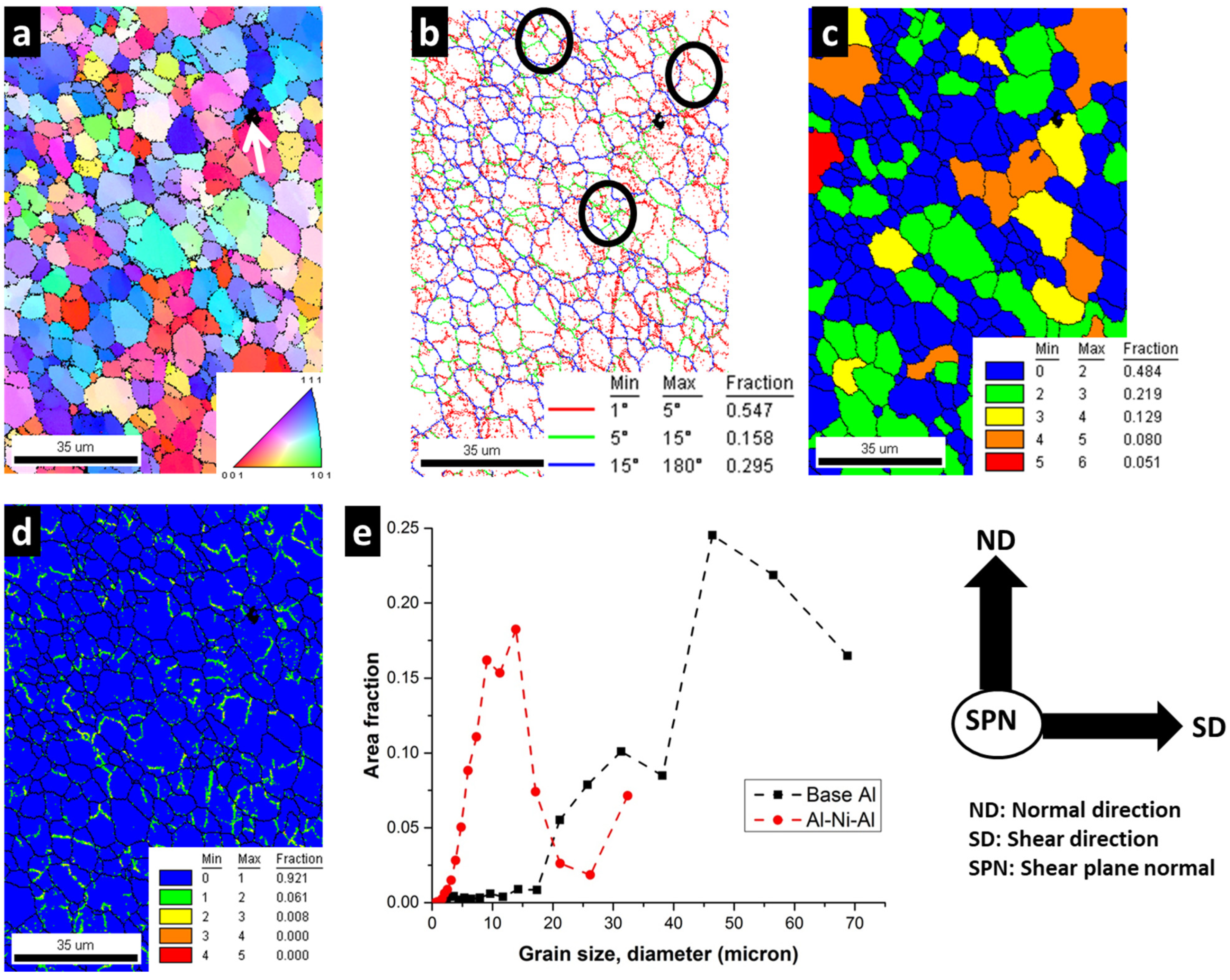
The EBSD scan acquired along the weld-nugget centerline is shown in Figure 10. A confidence-index (CI) threshold of 0.5 effectively excluded non-indexable second-phase particles (Ti, Ni, intermetallics) appearing as black regions (white arrows). Sub-resolution particles (<0.5 µm step size) were also excluded from orientation averaging. The IPF map (Figure 10a) illustrates a complete transformation to an equiaxed morphology, with average grain size decreasing from 40.2 ± 18.4 μm in the as-received state to 6.1 ± 2.3 μm in the nugget zone. The corresponding GBCD map, shown in Figure 10b, reveals that the HAGB fraction reduced to 30% (vs. 87% in base Al). It also reveals that the grain boundary of a few grains exhibits mixed boundary characteristics, which are marked with black circles. These prominent mixed-character boundaries are characteristic of dynamic-recovery-assisted continuous dynamic recrystallization (DRV-CDRX), which is the dominant grain-refinement mechanism under severe deformation and elevated temperatures encountered during FSW. The GOS map (Figure 10c) identifies 48% strain-free grains (GOS ≤ 2°), which is lower than base metal due to sub-grain nucleation in high-misorientation zones [19] (Table 2). A careful observation reveals that the locations with high GOS values are actually in regions where sub-grains are generated.
KAM map from the same scan area is constructed (Figure 10d). The degree of misorientation of a point with respect to its surrounding points due to dislocation density is represented by a table associated with KAM map. The microstructure exhibits only moderate residual dislocation density, consistent with efficient recovery during thermomechanical processing [20]. This microstructural state, characterized by fine equiaxed grains (Figure 10e), mixed grain boundary character, and spatially non-uniform but generally reduced residual strain, optimizes the strength–ductility compromise, which is critical for composite-matrix performance.
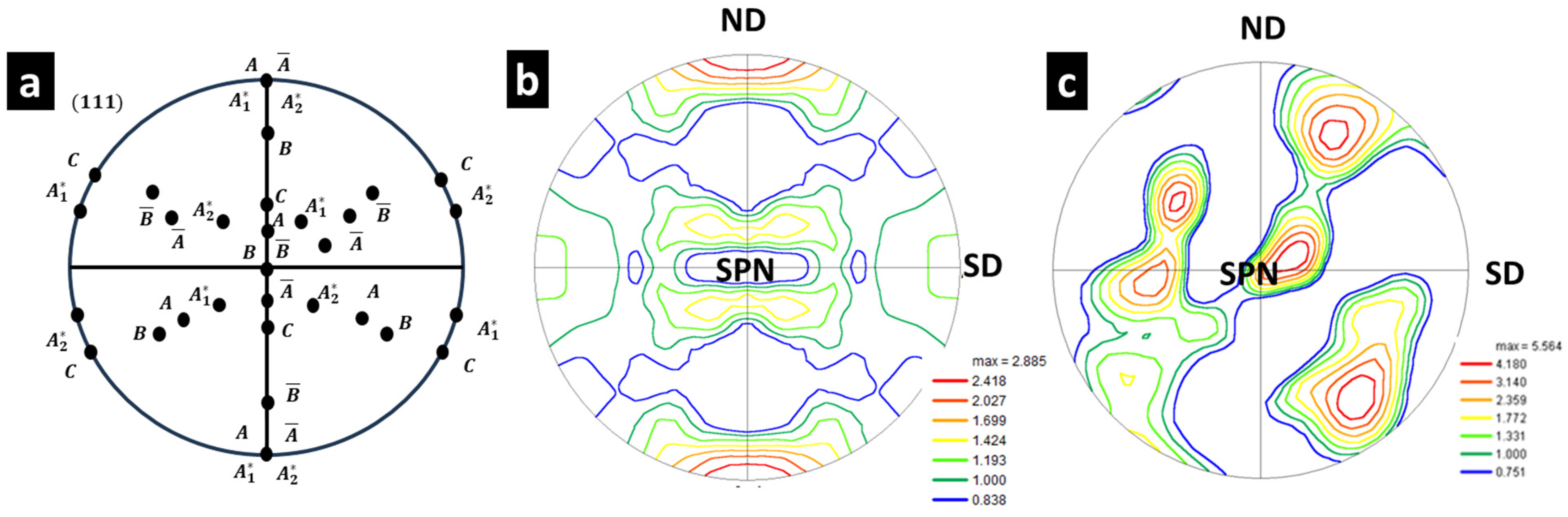
To understand the mechanism of microstructural evolution, micro-texture from the base Al and the cross-section of the weld nugget were constructed. The bulk texture of the welded sample before and after the welding is shown in Figure 11. Figure 11a shows the (111) pole figures representing ideal FCC shear texture components. The corresponding micro-textures measured from the surface and the center of the weld nugget are shown in Figure 11b and Figure 11c, respectively. It can be seen that the major texture component is A / A ¯ . However, the overall texture is very weak with a texture intensity of three. After welding, the center of the weld exhibits a B-type of texture with increased texture intensity of six, and the texture is not symmetric in the pole figure. The B / B ¯ components of shear texture are stable even at high temperatures, as observed in FSP. This clearly indicates that the combined effect of severe shear deformation during stirring and subsequent thermal exposure during cooling is consistent with DRV + CDRX-controlled grain evolution.

3.5. Mechanical Properties

3.5.1. Tensile Properties

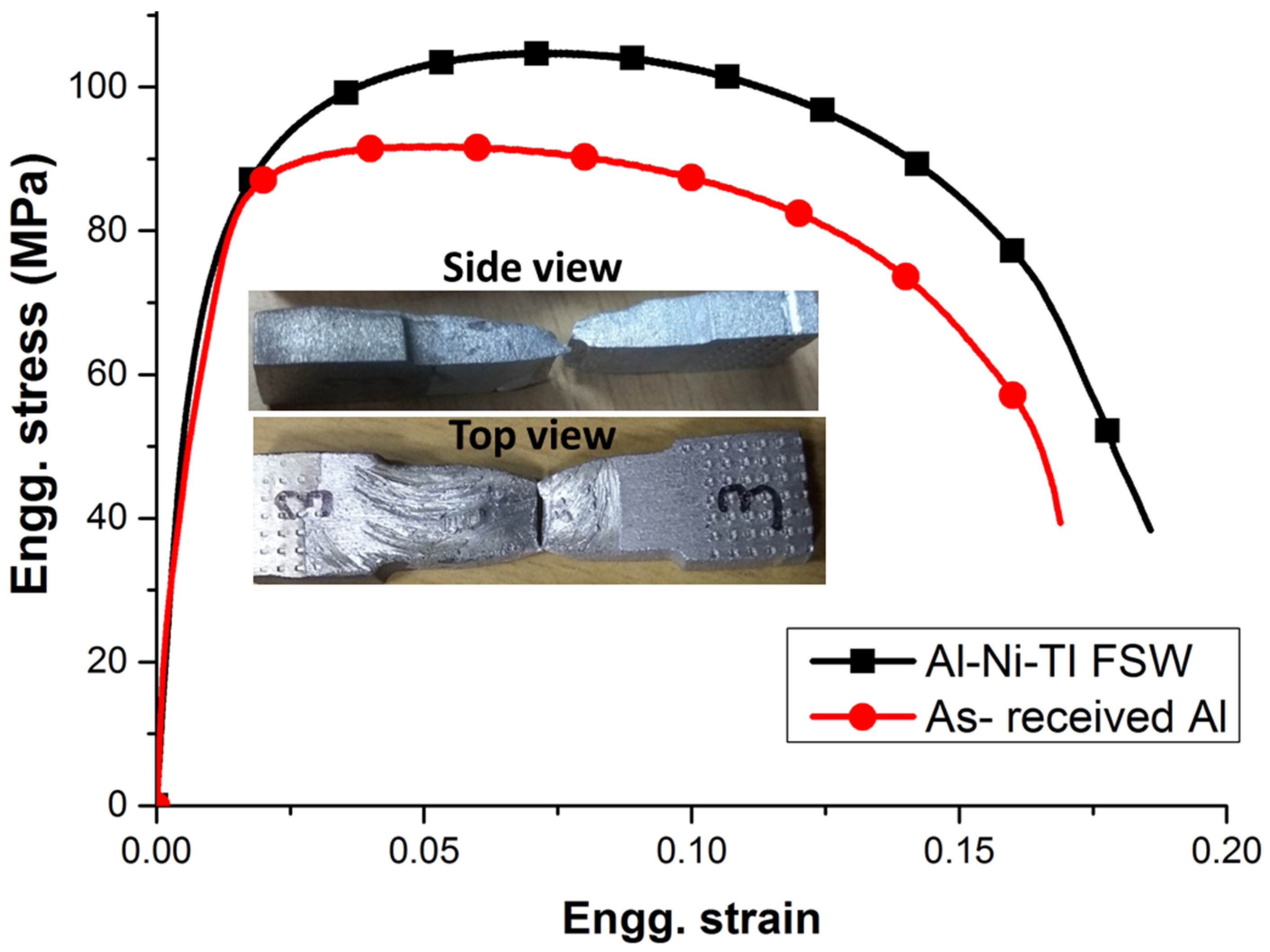
Tensile tests were carried out on specimens associated with the as-received Al plate and the weld region. Three tests (n ≥ 3) were performed for each sample, and the representative data was plotted. Yield strength (YS), ultimate tensile strength (UTS), and ductility (percent of elongation to fracture) of the as-received Al were measured as 82.4 ± 2.1 MPa, 106.3 ± 1.8 MPa, and 19.2 ± 0.24%, respectively. Figure 12 shows a plot of engineering stress versus engineering strain corresponding to the samples from the weld region. The weld region exhibits a YS of about 79.7 ± 2.8 MPa and UTS of about 104.2 ± 3.3 MPa, corresponding to ~98% of the base Al strength and ductility (17.1 ± 1.2), with elongation reaching about 90% of the base Al value. Taken together, these results show that the joint essentially preserves the strength of the base Al while maintaining a substantial fraction of its ductility, thereby demonstrating a tensile response characteristic of a metal–matrix composite.
To illustrate the impact of present results in the context of existing dissimilar Al/Ti FSW studies and to highlight their potential practical applications and industrial relevance, a summary table comprising a comparison of representative systems is provided in Table 3. The table describes the present Al–Ti–Ni system within the broader body of work on dissimilar FSW of cp-Al/cp-Ti with and without interlayers. Earlier studies on cp-Al/cp-Ti FSW report continuous or nearly continuous Al3Ti layers at the interface, as well as joint efficiencies typically limited to about 50–65% depending on tool offset position [10,13,14]. The results highlight the evolution of Al3Ti layers at the welding interface, irrespective of variations in processing conditions, due to thermomechanical effects; the results also show that they have a negative Gibbs free energy of formation. It indicates the brittle nature of the dominant Al3Ti intermetallic phase. The introduction of Nb, Zn, or Cu interlayers has been shown to alter interfacial reactions and partly reduce brittleness. In some cases, the addition of an interlayer significantly enhances joint efficiency and ductility [21]. Introduction of interlayers often results in the formation of complex, yet comparatively ductile, intermetallic phases. In contrast, the Ni interlayer investigated in the present study promotes the formation of Ni3Al-, AlTi-, and Al11Ti6-type intermetallics rather of a continuous Al3Ti layer, while concurrently producing a refined Al matrix with distributed Ti/Ni particles. This leads to a joint that retains ~98% of the base Al strength and ductility. Although ductility is lower than the base Al, it is comparable to or higher than values reported for Al/Ti-dissimilar joints in the literature [9,16,22,23,24,25]. The weld effectively behaves as an in situ metal matrix composite in the nugget zone rather than a conventional dissimilar weld. From an industrial perspective, it is rare to achieve a combination of high joint efficiency and preserved ductility, which is well-suited for structural applications at process parameters comparable to those used in current FSW practice. It is, therefore, suggested that the Ni interlayer strategy can be feasibly incorporated into existing joining methodologies for lightweight, damage-tolerant Al/Ti hybrid structures in aerospace and transportation sectors.

3.5.2. Fractography

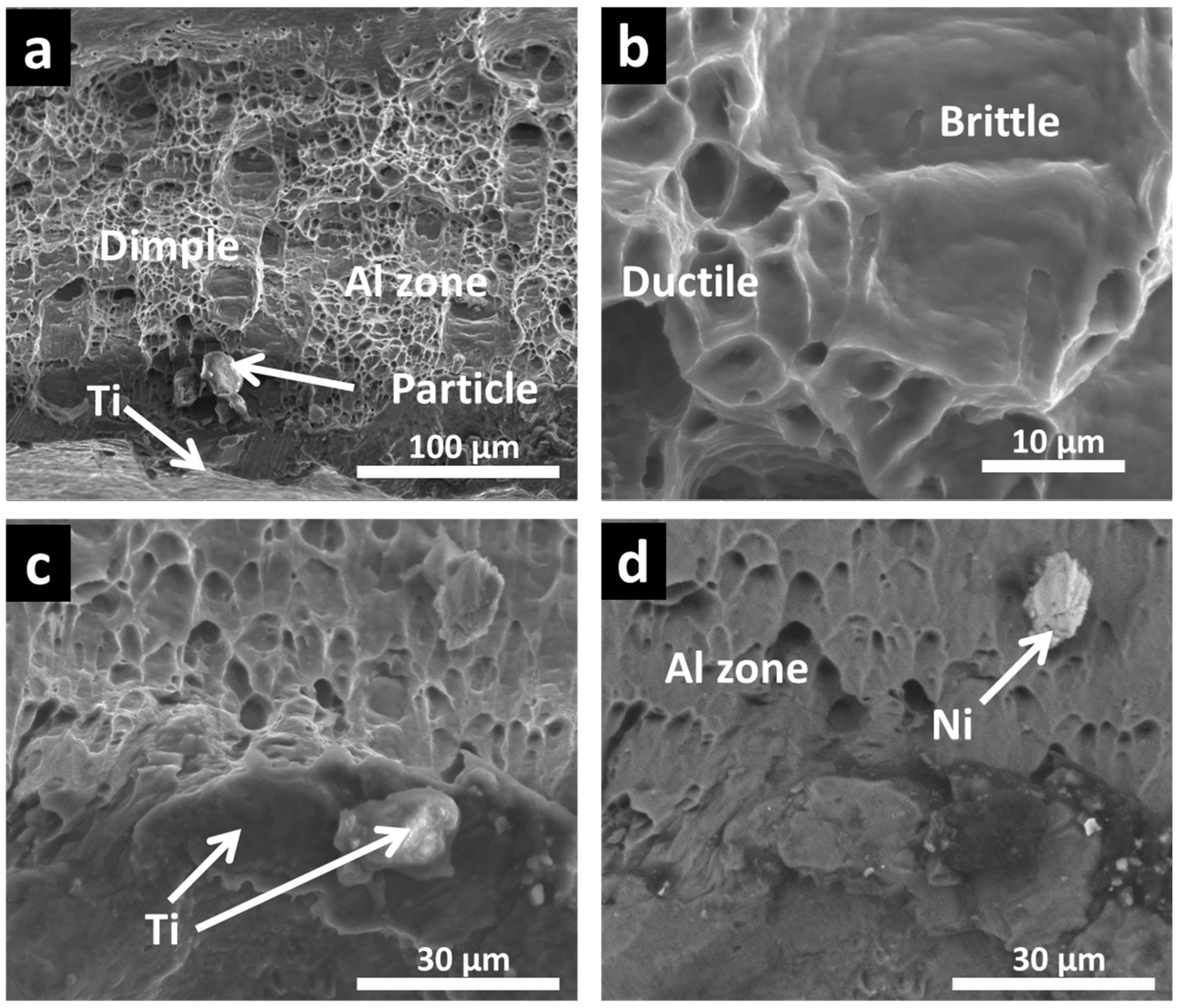
Figure 13 shows the typical fractography of the tensile specimens fractured within the weld nugget. Figure 13a displays a low-magnification SEM micrograph revealing an inhomogeneous fracture surface, which indicates a number of mechanisms responsible for the fracture of the weld sample. A number of dimples are seen on the surface. Both coarse and fine dimples are present, consistent with ductile failure processes in a heterogeneous microstructure. A magnified view of the fracture surface is shown in Figure 13b. A number of smooth locations are seen around the dimples, which suggests a brittle characteristic of the fracture. Figure 13c,d shows SEM micrographs in SE and BSE mode, respectively, exhibiting particles (Ti, Ni, and intermetallics) at the fracture surface where Al is still bonded with the particles.
Since the ductility of Ti, Ni, and associated intermetallics is lower than that of the Al matrix, fracture preferentially initiates at or near the particle–matrix interfaces and then propagates into the surrounding Al. Because these hard, low-ductility phases locally amplify stress and strain, microcracks first nucleate at the particle/matrix boundaries and subsequently grow through the softer, recrystallized Al ligaments, producing the observed mixture of dimples and smoother facets on the fracture surface. The observation of particles firmly embedded in dimples, along with the absence of interfacial debonding over large areas, indicates strong interfacial bonding between the particles and the recrystallized Al matrix. Consequently, the interface strength largely dictates the UTS of the weld, whereas the deformation capacity of the interface region and the ductility of the refined Al matrix control overall elongation.
The superior mechanical performance of the weld can thus be attributed to a synergy of the following factors: (i) the distribution of Ti- and Ni-containing particles throughout the weld nugget; (ii) the suppression of continuous brittle Al3Ti layers and the formation of alternative intermetallic phases with more favorable morphology; (iii) significant grain refinement and DRV-CDRX-driven microstructural evolution in the Al matrix. In addition, the high fraction of fine, well-distributed particles within the nugget acts as an effective obstacle to crack initiation and propagation, thereby retaining the ductility and damage tolerance of the joint while maintaining strength comparable to that of the base Al.

4. Conclusions

In the present investigation, FSW of commercially pure Al to Ti with a pure Ni interlayer was carried out, and the weld was characterized in detail to understand the mechanism associated with microstructure evolution and establish structure–property correlation. The following observations and findings are made in this study:
  • No defect is observed in the weld nugget. A thin layer of Al coating is observed on top of the weld. This coating essentially controls friction and temperature evolution during welding. In addition, qualitatively similar particle distribution is observed for both Ti and Ni particles and flakes in the weld nugget, as evidenced by XCT and cross-sectional microscopy, forming a mechanically mixed region that behaves as an in situ metal–matrix composite. Three-dimensional visualizations qualitatively demonstrate particle dispersion, supporting composite interpretation. The combination of a stable Al surface layer and a well-distributed population of Ti/Ni-containing fragments establish a heterogeneous, mechanically mixed nugget that behaves as an in situ metal matrix composite.
  • The particles are mechanically mixed with the Al matrix, leading to the formation of intercalated particles and diffusion at the interface, with the onset of the formation of a number of intermetallic compounds instead of only the brittle Al3Ti intermetallic compound. Ni presence correlates with Ni3Al/AlTi/Al11Ti6 formation and apparent suppression of continuous Al3Ti (XRD). The modified phases and mechanical mixing provide a more favorable balance between strength and toughness than would be expected for a continuous Al3Ti layer.
  • Aluminum in the weld nugget shows a substantial microstructural refinement with the average grain size decreasing from approximately 40–45 µm in the as-received state to about 6 µm in the nugget zone. The grain refinement is accompanied by a marked increase in low-angle and sub-grain boundary fractions. The mechanisms involved in microstructure evolution are DRV-driven CDRX. This results in a fine, equiaxed grain structure with a mixed grain boundary character and low residual misorientation, which provides a good compromise between strength and ductility in the Al matrix.
  • The weld exhibits comparable mechanical properties with respect to base Al. This is attributed to the distribution of particles in the weld nugget, reduction in brittle intermetallic compounds in the weld, and grain refinement of the Al matrix. The formation and distribution of a high fraction of fine particles within the weld nugget restrict crack propagation; therefore, the ductility of the weld is retained. Retaining ~98% of the ultimate tensile strength of the base Al while maintaining ~90% of its ductility demonstrates that the joint responds more like a reinforced composite than a conventional dissimilar weld. The formation and distribution of a high fraction of fine particles within the weld nugget restrict crack propagation and, therefore, retain the ductility of the weld.
  • Ni interlayer joints showed properties consistent with microstructure evolution. The results and findings demonstrate that controlled solid-state mechanical mixing with a Ni interlayer in FSW can be used as a robust route to fabricate Al-based in situ metal matrix composites with enhanced tensile performance.

Funding

This research received no external funding.

Data Availability Statement

The raw data supporting the conclusions of this article will be made available by the authors on request.

Acknowledgments

The author is deeply grateful to Satish Kailas and Satyam Suwas for their invaluable guidance, extensive knowledge sharing, and mentorship, which were instrumental in enabling the successful completion of this investigation. The author gratefully acknowledges the Defense Research and Development Organization (DRDO), the Department of Science and Technology (DST), and the Ministry of Human Resource Development (MHRD), India, for enabling the research facility associated with FSW/SEM. Additionally, the author would also like to thank the Institute X-ray facility and the Advanced Facility for Microscopy and Microanalysis (AFMM) at the Indian Institute of Science (IISc), Bangalore, for access to characterization equipment and technical assistance.

Conflicts of Interest

The authors declare no conflicts of interest that could have influenced the findings or interpretations presented in this paper.

References

  1. Kar, A.; Sharma, A.; Kumar, S. A Critical Review on Recent Advancements in Aluminium-Based Metal Matrix Composites. Crystals 2024, 14, 412. [Google Scholar] [CrossRef]
  2. Soni, R.; Verma, R.; Kumar Garg, R.; Sharma, V. A critical review of recent advances in the aerospace materials. Mater. Today Proc. 2024, 113, 180–184. [Google Scholar] [CrossRef]
  3. Möller, F.; Thomy, C.; Vollertsen, F. Joining Oftitanium-Aluminium Seat Tracks for Aircraft Applications—System Technology and Joint Properties. Weld. World 2012, 56, 108–114. [Google Scholar] [CrossRef]
  4. Fuji, A. In situ observation of interlayer growth during heat treatment of friction weld joint between pure titanium and pure aluminium. Sci. Technol. Weld. Join. 2002, 7, 413–416. [Google Scholar] [CrossRef]
  5. Wilden, J.; Bergmann, J.P.; Herz, S. Properties of diffusion welded hybrid joints titanium/aluminum. In Brazing and Soldering: Proceedings of The 3rd International Brazing and Soldering Conference, Crown Plaza Riverwalk Hotel, San Antonio, Texas, USA, 24-26 April 2006; ASM International: Almere, The Netherlands, 2006; pp. 338–343. [Google Scholar]
  6. Kim, Y.C.; Fuji, A. Factors dominating joint characteristics in Ti—Al friction welds. Sci. Technol. Weld. Join. 2002, 7, 149–154. [Google Scholar] [CrossRef]
  7. Zhang, C.Q.; Robson, J.D.; Ciuca, O.; Prangnell, P.B. Microstructural characterization and mechanical properties of high power ultrasonic spot welded aluminum alloy AA6111–TiAl6V4 dissimilar joints. Mater. Charact. 2014, 97, 83–91. [Google Scholar] [CrossRef]
  8. Li, B.; Zhang, Z.; Shen, Y.; Hu, W.; Luo, L. Dissimilar friction stir welding of Ti–6Al–4V alloy and aluminum alloy employing a modified butt joint configuration: Influences of process variables on the weld interfaces and tensile properties. Mater. Des. 2014, 53, 838–848. [Google Scholar] [CrossRef]
  9. Saravana Sundar, A.; Radhika, N.; Kumar, A. Role of submerged friction stir welding in reducing intermetallic growth and enhancing microstructure in dissimilar Al-Ti joints. Sci. Rep. 2024, 14, 26908. [Google Scholar] [CrossRef] [PubMed]
  10. Kar, A.; Kailas, S.V.; Suwas, S. Friction stir welding of aluminum to titanium: Quest for optimum tool-offset, deformation of titanium, and mechanism of joint formation. Int. J. Adv. Manuf. Technol. 2023, 128, 1943–1956. [Google Scholar] [CrossRef]
  11. Kumar, K.; Kailas, S.V. On the role of axial load and the effect of interface position on the tensile strength of a friction stir welded aluminium alloy. Mater. Des. 2008, 29, 791–797. [Google Scholar] [CrossRef]
  12. Meengam, C.; Sillapasa, K. Evaluation of Optimization Parameters of Semi-Solid Metal 6063 Aluminum Alloy from Friction Stir Welding Process Using Factorial Design Analysis. J. Manuf. Mater. Process. 2020, 4, 123. [Google Scholar] [CrossRef]
  13. Kar, A.; Suwas, S.; Kailas, S.V. Multi-Length Scale Characterization of Microstructure Evolution and Its Consequence on Mechanical Properties in Dissimilar Friction Stir Welding of Titanium to Aluminum. Metall. Mater. Trans. A 2019, 50, 5153–5173. [Google Scholar] [CrossRef]
  14. Kar, A.; Mathiyalagan, S.; Malopheyev, S.; Kaibyshev, R.; Suwas, S.; Kailas, S.V. Investigation on Friction Stir Welding Parameters: Mechanical Properties, Correlations and Corrosion Behaviors of Aluminum/Titanium Dissimilar Welds. Crystals 2024, 14, 305. [Google Scholar] [CrossRef]
  15. Zhang, X.; Shi, L.; Wu, C.; Yang, C.; Gao, S. Multi-phase modelling of heat and mass transfer during Ti/Al dissimilar friction stir welding process. J. Manuf. Process. 2023, 94, 240–254. [Google Scholar] [CrossRef]
  16. Sundar, S.A.; Kar, A.; Mugada, K.K.; Kumar, A. The Feasibility of Static Shoulder Friction Stir Welding in Joining Dissimilar Metals of Al6061 and Ti6Al4V. Metals 2024, 14, 128. [Google Scholar] [CrossRef]
  17. Yang, W.; Wang, P.; Huang, X.; Zhang, S. Thermodynamic analysis of the Al–Ni system. Intermetallics 2022, 149, 107647. [Google Scholar] [CrossRef]
  18. Ansara, I.; Sundman, B.; Willemin, P. Thermodynamic modeling of ordered phases in the NiAl system. Acta Metall. 1988, 36, 977–982. [Google Scholar] [CrossRef]
  19. Suresh, K.S.; Kumar, N.; Mishra, R.S.; Suwas, S. Evolution of Microstructure and Texture in Friction Stir Processed Al-Mg-Mn Alloy. Mater. Sci. Forum 2013, 753, 247–250. [Google Scholar] [CrossRef]
  20. Saravana Sundar, A.; Adepu, K.; Mugada, K.K.; Satyanarayana, M. Effect of the static shoulder on microstructural, textural, and mechanical characteristics during friction stir welding of Al6061. Proc. Inst. Mech. Eng. Part L J. Mater. Des. Appl. 2023, 237, 144–154. [Google Scholar] [CrossRef]
  21. Kar, A.; Kailas, S.V.; Suwas, S. Effect of Zinc Interlayer in Microstructure Evolution and Mechanical Properties in Dissimilar Friction Stir Welding of Aluminum to Titanium. J. Mater. Eng. Perform. 2018, 27, 6016–6026. [Google Scholar] [CrossRef]
  22. Österreicher, J.A.; Pfeiffer, C.; Kunschert, G.; Weinberger, T.; Schlögl, C.M.; Suppan, W.; Radlmayr, K.M. Dissimilar friction stir welding and post-weld heat treatment of Ti-6Al-4V and AA7075 producing joints of unprecedented strength. J. Adv. Join. Process. 2024, 9, 100213. [Google Scholar] [CrossRef]
  23. Mubiayi, M.P. Current Developments in Friction Stir Welding (FSW) and Friction Stir Spot Welding (FSSW) of Aluminium and Titanium Alloys. Eng. Proc. 2023, 56, 184. [Google Scholar]
  24. Choi, J.-W.; Liu, H.; Fujii, H. Dissimilar friction stir welding of pure Ti and pure Al. Mater. Sci. Eng. A 2018, 730, 168–176. [Google Scholar] [CrossRef]
  25. Kar, A.; Suwas, S.; Kailas, S.V. Two-pass friction stir welding of aluminum alloy to titanium alloy: A simultaneous improvement in mechanical properties. Mater. Sci. Eng. A 2018, 733, 199–210. [Google Scholar] [CrossRef]
  26. Kar, A.; Choudhury, S.K.; Suwas, S.; Kailas, S.V. Effect of niobium interlayer in dissimilar friction stir welding of aluminum to titanium. Mater. Charact. 2018, 145, 402–412. [Google Scholar] [CrossRef]
  27. Kar, A.; Suwas, S.; Kailas, S.V. Significance of tool offset and copper interlayer during friction stir welding of aluminum to titanium. Int. J. Adv. Manuf. Technol. 2019, 100, 435–443. [Google Scholar] [CrossRef]
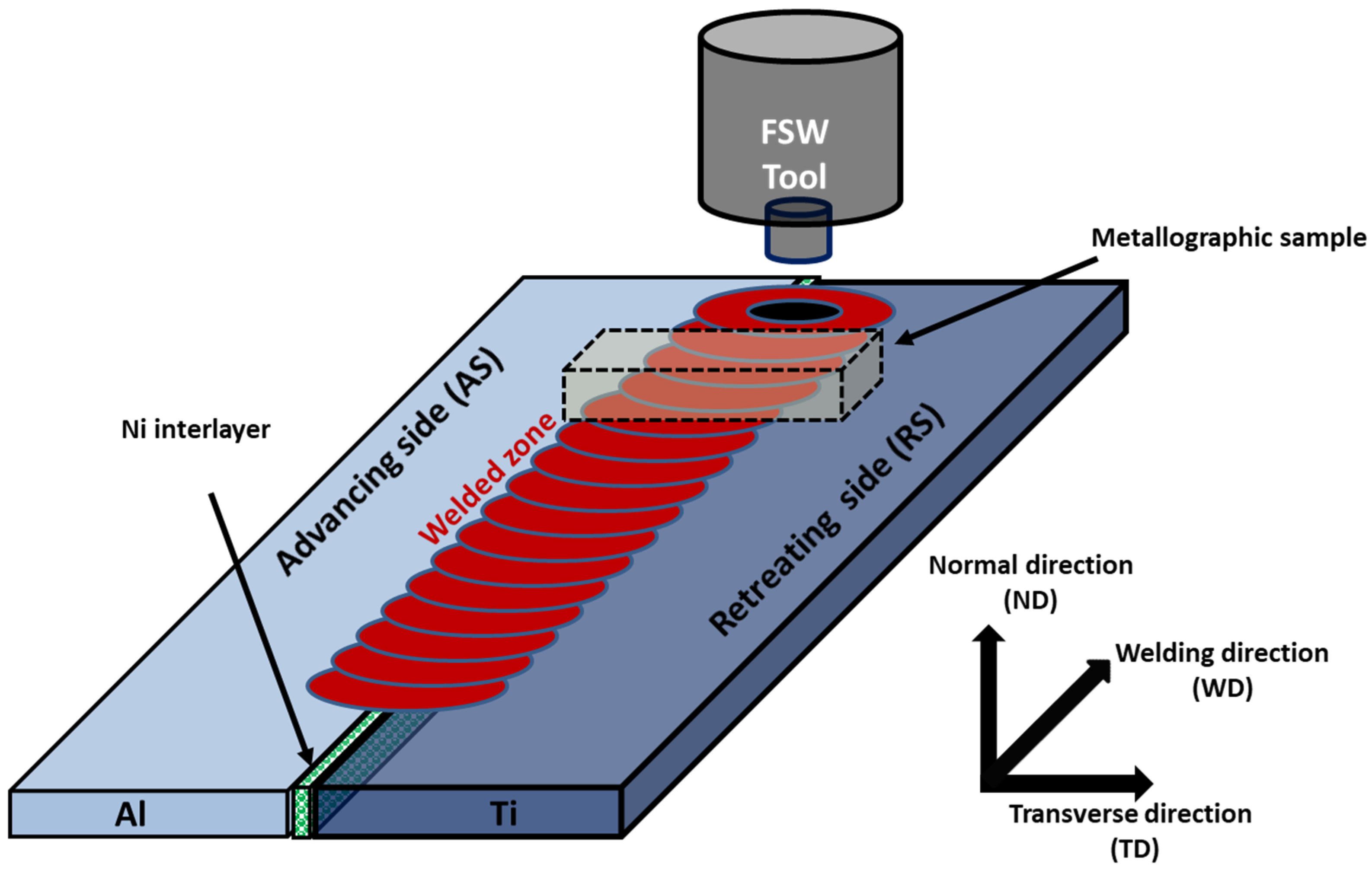
Figure 1. Schematic illustration of the Al/Ti FSW process with Ni interlayer.
Jmmp 10 00100 g001
Figure 2. Schematic of the tensile specimen geometry used to evaluate the mechanical properties of the welds, showing dimensions and the position of the weld nugget within the gauge section.
Jmmp 10 00100 g002
Figure 3. Cross-sectional macrostructure of the weld, showing defect-free consolidation and particle distribution; the wider nugget at the top and the continuous Al coating formed at the surface are also indicated.
Jmmp 10 00100 g003
Figure 4. X-ray computed tomography (XCT) of the Al/Ti friction stir-welded sample incorporating a Ni interlayer, illustrating the three-dimensional distribution of Ti (green) and Ni (red) in the weld nugget: (a) isometric view, (b) front view, and (c) side view from the bottom of the weld, with the mechanically mixed zone highlighted by a circle.
Jmmp 10 00100 g004
Figure 5. Three-dimensional reconstruction of the weld nugget from XCT images; (a) cross-sectional TD-ND view, (b) top TD-WD view and (c) bottom TD-WD view, revealing the location of particles, variation in particle size, and morphologies in the weld nugget. Mechanical mixing with the final particles was noticed in the center of the weld nugget.
Jmmp 10 00100 g005
Figure 6. X-ray diffraction patterns obtained from welds, showing the evolution of multiple intermetallic compounds, including Ni3Al, AlTi, and Al11Ti6, in the weld nugget.
Jmmp 10 00100 g006
Figure 7. Two locations in the weld nugget show (a) severe deformation and mechanical mixing of Al, Ti, and Ni, with deformed Ti particles interacting with Ni and (b) a Ni/Ti interface region that restricts direct Al/Ti contact.
Jmmp 10 00100 g007
Figure 8. (a) Weld interface and (b) higher-magnification view of the interfacial zone highlighted by the square in (a). (c) Superimposed EDS elemental map and individual maps of (d) Al, (e) Ni, and (f) Ti, showing the distribution of fine Ni-containing particles within the mechanically mixed Al–Ti interfacial region. Al = red color, Ni = blue color, and Ti = green color.
Jmmp 10 00100 g008
Figure 9. EBSD maps of the as-received Al: (a) IPF map showing elongated, randomly oriented grains; (b) grain boundary character distribution (GBCD) map distinguishing subgrain, low-angle, and high-angle boundaries; (c) grain orientation spread (GOS) map indicating low overall internal misorientation; and (d) kernel average misorientation (KAM) map highlighting the low dislocation density in the starting microstructure.
Jmmp 10 00100 g009
Figure 10. EBSD maps of Al at the center of the weld nugget: (a) IPF map showing a fine, equiaxed grain structure; (b) GBCD map revealing a reduced fraction of high-angle grain boundaries and mixed boundary character consistent with DRV-assisted CDRX; (c) GOS map and (d) KAM map identifying regions of strain-free and moderately strained grains. A confidence-index cutoff of 0.5 was used to exclude Ti, Ni, and intermetallic particles from the analysis. (e) Grain size distribution revealing grain refinement of the scan area, which is represents ND, SD and SPN.
Jmmp 10 00100 g010
Figure 11. (a) Standard (111) pole figure with ideal FCC shear texture components; (b) measured (111) pole figure of the Al base material before welding, showing weak texture; and (c) measured (111) pole figure at the center of the weld nugget, showing the development of B-type shear components and increased texture intensity. SPN: shear plane normal; SD: shear direction; ND: normal direction.
Jmmp 10 00100 g011
Figure 12. Engineering stress–strain curves for the as-received Al and the weld region, demonstrating that the weld retains nearly the full ultimate tensile strength of the base material while exhibiting 90% retained ductility. Three samples (n = 3) were tested for each sample.
Jmmp 10 00100 g012
Figure 13. Fractography of a tensile specimen fractured within the weld nugget: (a) low-magnification SEM image showing a multimodal distribution of dimples indicative of predominantly ductile fracture; (b) higher-magnification view revealing local smooth regions associated with brittle features; and SEM images in (c) secondary electron (SE) and (d) backscattered-electron (BSE) modes showing Ti, Ni, and intermetallic particles at the fracture surface, with the arrow indicating fracture initiation at a Ti-particle interface.
Jmmp 10 00100 g013
Table 1. Chemical composition of the as-received materials used in the present investigation.
CuMgSiFeMnTiZnCAlOther
cp-Al0.0020.0030.1700.1200.0020.0090.003 99.6610.030
cp-Ti---0.300-99.510-0.080-0.110
Table 2. Summary of EBSD-related analysis and results.
EBSD InformationAs-Received AlWeld Nugget
Scan area118 × 88 μm284 × 68 μm2
Step size0.5 μm0.5 μm
Average grain size40.2 ± 18.4 μm6.1 ± 2.3 μm
HAGB (>15°); CI ≥ 0.587%30%
LAGB (5–15°)9%42%
SubGB (<5°)4%28%
Strain-free (GOS < 2°)95%48%
Avg KAM0.42°1.12°
Table 3. Summary of the current state-of-the-art, in terms of FSW of dissimilar welding of cp-Al/cp-Ti and the impact of the Ni interlayer.
Dissimilar FSW of MetalsWelding ParametersResearch Highlights and ContributionsReferences
FSW of cp-Al/cp-TiTRS = 600–1000 rpm
WS = 40–100 mm/min
Weld interface varies with processing parameters, tool offset and morphology of Al3Ti. Joint efficiency 50–65%.[10,13,14]
FSW of cp-Al/cp-Ti with Nb interlayerTRS = 900 rpm
WS = 90 mm/min
Formation of NbTi along with Al3Ti. Reduction in brittleness.
Joint efficiency = 65%.
[26]
FSW of cp-Al/cp-Ti with Zn interlayerTRS = 900 rpm
WS = 90 mm/min
Formation of Al-Zn solid solution. TiZn3 and Al3Ti. Reduction in brittleness.
Joint efficiency = 128% along with significantly high ductility (48%)
[21]
FSW of cp-Al/cp-Ti with Cu interlayerTRS = 800 rpm
WS = 90 mm/min
Mechanical mixing results in a reduction in Al3Ti in the presence of copper.[27]
FSW of cp-Al/cp-Ti with Ni interlayerTRS = 800 rpm
WS = 40 mm/min
Formation of Ni3Al-, AlTi-, and Al11Ti6-type intermetallics instead of a continuous Al3Ti layer.
Joint efficiency = 98%. Retaining welding ductility (joint ductility as 17.1 ± 1.2% and base Al as 19.2 ± 0.24%).
Current study
Disclaimer/Publisher’s Note: The statements, opinions and data contained in all publications are solely those of the individual author(s) and contributor(s) and not of MDPI and/or the editor(s). MDPI and/or the editor(s) disclaim responsibility for any injury to people or property resulting from any ideas, methods, instructions or products referred to in the content.