1. Introduction
Unmanned Aerial Vehicles (UAVs) [
1], often referred to as
drones by non-technical users, are known in the academic literature under a variety of names: UASs (Unmanned Aerial Systems) [
2], RPAs (Remotely Piloted Aircrafts) [
3], ROAs (Remotely Operated Aircrafts) [
4] or, mainly, UAVs. While this technology is not new ([
5], reports on the U.S. military using UAVs for operations as far back as the Vietnam War) it has recently (in the last 5–10 years) become commercially available to civilian professional users as well as hobbyists. There are already a large number of diverse devices and different device types commercially available and the difference in price can be substantial between them [
6], with toys being available for less than
$100 while professional non-military devices can easily cost in excess of
$100,000 [
7]. Recent developments have resulted in UAVs with acceptable performance becoming available at an affordable cost. The use of drones for preliminary data collection is becoming common practice for civilian applications in the areas of, for example, precision agriculture [
8] and civil defense such as fire fighting [
9], traffic management [
10] or to locate victims [
11].
The relatively young field of UAV-technologies has not yet agreed on a unified classification system encompassing all devices and there are many ways to categorize UAVs [
12]. For the foreseeable future regulatory bodies will continue to impose different regulations and classifications on UAVs [
13] and those regulations may be subject to frequent change and amendment. The use of UAVs in public airspace touches on a number technical and societal concerns and challenges [
14]. The available devices differ in manufacturer, type and capabilities and have been used for a wide variety of applications and missions. Some fixed wing UAVs can remain airborne for hours (cf.
Table 1) circling over certain areas while cheap off-the-shelf quadrotor currently have an expected flight-time of about 15 to 20 min [
13]. Special purpose UAVs can remain in the air for up to two weeks [
15] or longer and as technologies continue to improve these performance values are only expected to get better [
16].
1.1. Challenges and Stepping Stones
In the interest of full disclosure we would like to emphasize that the work and the results presented in this article are from simulations only. The hardware and simulation framework presented in
Section 3 makes this clear but we feel the need to justify this shortcoming at this point to avoid disappointment. Our work is based on theoretical investigations [
17,
18,
19,
20]. At NEC Research Labs, a drone was custom built for this project and flown as shown in Figure 6.
However, as explained in
Section 3, the legal and operational obstacles for operating and flying a swarm of drones proved to be prohibitively challenging and, more importantly, restricting: the legal setting at the time required (and, to our knowledge, still does require) a pilot for each devices
as well as the ability to take control of a drone at any time. Operating a swarm of 25 drones would therefore require 25 pilots, with each individual tracking the specific drone allocated to the respective pilot at all times. In addition to the HR challenges this poses and given the intended application domain and the application itself, maintaining continuous
line of sight can only be guaranteed by subjecting the test scenario to some rather restricting conditions. Furthermore, the very concept of autonomous operation is problematic under the letter of the law in some countries: in The Netherlands, the flying of drones in full autonomy is currently (to our knowledge) forbidden by definition and (again, to our best knowledge) not possible. This will change in the near future, with first legislations for autonomously operating drones as well as an effort to unify UAV legislations within the European Union underway.
Meanwhile, the Intelligent Autonomous Systems (IAS) group at TNO is taking steps to partner with the Dutch Military to conduct a series of preliminary tests over military terrain (side-stepping the laws for civilian airspace) with the express goal to facilitate the testing and operating of UAVs in full autonomy. As this is the subject of an ongoing planning effort we have decided to submit this manuscript with simulated results only and to leave the full field-testing of the algorithm as future and expected work, see
Section 5. The hardware available at IAS, which is also the hardware expected to be used for forthcoming projects on UAV swarming, is shown in
Figure 1,
Figure 2 and
Figure 3.
1.2. Relevant Application Areas
In Reference [
6], we provided an overview over some of the most promising non-military application areas and the challenges of operating UAVs and especially swarms of UAVs. The United States Office of the Secretary of Defense (OSD) distinguishes more than twenty unique UAV mission types [
12], ranging from intelligence, surveillance [
21] and reconnaissance missions [
5], over locating victims [
11] to, for example, fire fighting [
9]. The majority of the applications in Reference [
6] are sensing focused missions (as opposed to applications requiring actuation, that is, the manipulation of objects in the physical environment). In the context of the article at hand we would like to emphasis 4 main application areas where UAVs are already used for various data-collection/sensing centered missions. These areas, which are briefly introduced below and for which the algorithm proposed in this article was mainly developed, are:
1.2.1. Precision Agriculture
In the context of agriculture related monitoring applications one of the defining characteristics is the need for detailed information for large areas. This is especially the case in the context of environmental or weather monitoring missions [
10]. The provided information has to be timely, as changing conditions may affect the data collection or the measured quantity and, if, for example, abnormal readings a reported, of high resolution and accuracy so as to identify critical issues as early and precise as possible [
22]. Agriculture has of course been around for millennia but the traditional approach to data collection is through sampling, which is inherently unreliable, imprecise and suffering from a large time delay between collecting the data and evaluating it. Especially in the context of pest monitoring [
22] and extreme conditions [
16], it would be of added benefit to be able to deploy a swarm of devices that can cover an even larger area while at the same time being able to dispatch one of its members to investigate specific locations without the swarm losing sight of the entire field to do so.
1.2.2. Disaster Response and Relief
UAVs can be deployed [
23] during or after disasters to contribute to disaster management operations by, for example, performing logistic tasks such the delivery of hardware and resources to incident sites [
9], recovering hazardous material [
16], assisting with traffic monitoring and management [
10,
16] or monitoring structures and inspecting terrain [
13] before human operatives are permitted access. By augment or replacing remaining sensing capability [
32] in an environment [
9], UAVs can play a crucial role [
23], especially when existing infrastructure is compromised, malfunctioning or disconnected. According to Reference [
10] we will see see advances in the areas of cloud computing, wireless sensors, networked unmanned systems as well as big/open data over the next few years, which has the potential to make drones the ideal candidate for mobile/aerial urban sensing platforms [
21]. UAVs can serve as flexible mobile platforms [
10] for general monitoring [
9,
11] or monitoring and surveillance [
10,
16] missions but also to, for example, provide situational awareness support [
13], surveil forrest and wildfires [
16], detect victims or their life-signs [
11] and participate in search and rescue or aerial tracking [
16].
Disasters often result in partial or total loss of communication and data-collection infrastructure and operations during or in the wake of, a disaster are generally highly dynamic (people, victims, resources and threats move as the situation develops, often in response to disaster response activities). The use of multiple UAVs, operating as a single unit in formation (i.e., a swarm [
21]) and acting as mobile sensor networks [
10] to monitor civil defense personal or disaster victims [
11] or for tracking and surveillance tasks in general [
16] offers a number of obvious benefits. Enabling swarms capable of autonomously assessing the quality of the collected data with the aim to continuously self-organize into constellations that improve upon it is the domain of the presented algorithm.
1.2.3. Smart City Applications and Civil Protection
UAVs, by their mobile nature are ideal candidates for mobile/aerial urban sensing platforms [
21]. Clearly there is an overlap between UAV applications in the context of natural or man-made disasters and their use in the context of a smart city, not the least because major civil defense incidents can be classified as disasters (and of course because natural disasters can affect a city, causing wide-spread civil defense operations). However, even under normal operations a sensor-enhanced urban infrastructure can benefit greatly from mobile sensing devices delivering data for a plethora of applications, ranging from simple environment/weather monitoring [
10] over resource tracking [
16] and urban surveillance [
21] to package delivery [
9] and traffic monitoring [
16]. During large events they can be used to provide situational awareness support [
13], deliver medical supplies to congested areas [
9] and monitor first responder personal and resources [
11], for example, for fire fighters [
9].
Their decreasing cost, increasing ease to operate and the fact that vast varieties of sensors can be mounted on affordable drones makes them ideal candidates for mobile/aerial urban sensing platforms [
21]. Operating a swarm of such devices [
21] for, for example, aerial tracking [
16] which can autonomously decide to dispatch a swarm-member to provide a closer look (i.e., higher resolution data or more accurate measurements) while at the same time dynamically reorganizing to continue to cover an entire area can have many advantages over using individual devices in isolation as stand-alone applications.
1.2.4. Land Administration and Wildlife Protection
Recently, UAVs have been successfully used for civil- [
9] and cargo-supply [
30], terrain inspection [
13] and various search and rescue operations [
16,
30]. UAVs are used for water management and biofuel production [
2] or to monitor areas [
10] for wild-life protection (e.g., U.S. animal rights groups deploying drones to monitor offenders) [
1]. UAVs are being used all over the globe to this end—for example, the World Wildlife Fund (WWF) uses fixed wing drones like the FPV Raptor in the Bardia National Parks (Nepal) to fight poaching and illegal wildlife trade [
29,
31] and in some of Africa’s national parks UAVs are used to actually close in on the poachers to engage them [
29].
Especially in the context of herd surveillance swarm operations can be of great benefit or even crucial to the mission: when using a population of UAVs as flexible mobile platforms [
10], equipped with hardware that allows them to locate heat sources [
13], the ability to maintain uninterrupted coverage over the entire herd is critical to enable the tracking [
16] of individual animals. At the same time, preliminary analysis of IR-video footage might make it necessary for one drone to approach a specific animal for a better reading, so as to ascertain the health status of the individual.
1.3. Optimization and Self-Organization in Nature
Collective behaviour (e.g., clustering, collaboration and signal processing) based on self-organization [
33] has been shown in group-living animals from insects to vertebrates and even at the cell level [
34]. Engineers and computer scientists have a long history of applying principles and approaches found in nature to challenges in their respective domains. In computing science this is often done to increase the accuracy of models and to improve algorithms (cf. Reference [
35]). Indeed, nature-inspired approaches (e.g., Reference [
36]) have the potential to be extremely efficient [
37]. With regard to swarming applications, especially the behaviour of social insects such as ants, termites and bees has received a lot of attention in the past years [
38]. The social insect metaphor for problem solving emphasizes distributedness, interaction between members of a population, flexibility and robustness [
39]. The distributed nature of self-organization is one of its defining characteristics and may be its most advantageous feature. Distributed sensing can be achieved using only rudimentary cognition may be widespread across biological taxa, in addition to being appropriate and cost-effective for computational agents [
40]. It has been shown that global goals can be achieved by local processing and by using only local information [
41]. The growing understanding of complex collective behaviour offers the prospect of creating artificial systems controlled by emergent collective behaviour [
42].
1.4. Heuristics and Meta-Heuristics
Computer scientists have studied models from theoretical biology and applied the underlying principles to a variety of problems, often in the form of heuristics. Heuristics (from the Greek
í
:
“to find”,
“to discover”) are approaches that
estimate or
find (in contrast to
deterministically derive or
deduce) good solutions to problems. In computing science there are many problems that while theoretically trivial to solve (e.g., there is a winning strategy for the game of Chess) are prohibitively complex, making the calculation of the optimal solution too computationally expensive to be even remotely feasible. Heuristics [
43] can find
very good solutions in very little time (sometimes increasing only linearly with the size of the problem) but they do so at the danger of missing the
best possible solution. Since many problems require only a certain quality of the solution, investing time and effort to improve the solution further is a waste of resources.
If a heuristic exploits a property common to many problems then it is called a
meta-heuristic because it can be applied to an entire class of problems. It is not uncommon for meta-heuristics to be inspired by naturally occurring phenomena, which are often taken from the fields of physics and biology. The approaches to UAV swarming algorithms in our lab (cf. patent applications [
44,
45,
46,
47]) have shown an affinity for such nature-inspired approaches and are inspired by social insects (cf. References [
17,
18,
19,
20]).
The field of meta-heuristics is broad and complex and the scope of this article does not allow an overview to do it justice. For a broad overview and a useful compilation of nature-inspired approaches (including the algorithms) we suggest Reference [
48] which is also available online for free (
http://www.cleveralgorithms.com/).
2. Swarm Based Real-Time Data Collection
There are a number of application areas where drones are already heavily used (cf.
Section 1.2) for data-collection missions. As with most real-world applications, there is a temporal element to most of these missions, meaning that the world is changing while measurements are performed. For many measurements this is even a crucial aspect, as we want to know how some sensor reading evolves over time. There are, however, applications where measurements performed by a single sensor or sensing units are negatively affected by the fact that the measured environment is dynamic. This is especially the case when the objective of the data-collection requires measurements are various points (ideally at the same time) and when the objects that are measured are themselves not static (e.g., moving around).
Examples
A feature that sets our work apart from other swarm-based surveillance and assessment applications (such as the use of collectives of UAVs to locate land mines [
49]) is the requirement to maintain the entire area under surveillance while at the same time allocating increased attention to some specific location within the area. We briefly discuss two real-world examples for our problem to provide a framing for the approach and the results discussed in this article:
A child has gone missing at a massive public event, such as for example, the 4th of July parade. Identifying properties (such as wearing a red jacket and being ≈ 125 cm in height) are known. The task at hand is to check an entire road segment. This requires being able to zoom in for closer investigation if a red object of the appropriate height is spotted. Since children can be extremely mobile, maintaining area coverage is extremely important if we wish to reliably check an area.
A herd of animals is under aerial surveillance, be it to establish the health status of the herd or because a predator reported among them. It is virtually impossible to perform a full close-up evaluation of all individuals without maintaining line of sight on the entire herd. It might be possible to identify every individual but the operational cost of re-finding individuals on the basis of their markings is prohibitively high (and might require additional sensors).
The above examples could both be (and have been, cf. References [
13,
29,
31]) realized using UAVs (or existing hardware such as traffic cameras or, looking into the future, swarms of satellites [
20]). What we propose is to operate UAV swarms under the control of decentralized algorithms that enable a collective to self-organize continuously so as to adapt to the changing environment. In the context of this article, the
changes in the environment are changes in the resolution required for each individual under observation. In other words, we set aside the movement of the individual objects under surveillance (the argument being that the tracking of objects within a data feed is simply a question of computational resources) and focus on the ability to allocate increased sensing capabilities to individuals without sacrificing a minimum resolution for everyone under surveillance.
In the above examples we make use of sensors and without addressing the current state of the art with regard to commercially available sensors and sensing equipment, let’s just say that the sensors in our examples could be video cameras or infra-red cameras/sensors, respectively. The gimball mounted camera, shown in
Figure 1 under one of TNO IAS’s AceCore NEO drones (cf.
Figure 2 and
Figure 3) is an example of the hardware that could be used in a field test for the above mentioned examples.
Generally speaking, the sensing capabilities of any equipment are bounded. This means that in order to increase the level of detail (e.g., in case of a camera or an IR-sensor: the image resolution) one has to reduce the area that is covered. Assuming that there is some leeway and overlap in coverage, then there is the opportunity for re-arranging allocations so as to find a deployment which improves the current performance. If continuous coverage over an entire area is a hard constraint (as it is for certain search and rescue missions), then this can be achieved by handing over coverage over locations to other devices which currently operate under lower resolution requirements.
2.1. Problem Statement
We address the scenarios where a number of UAVs are operating as a single functional unit (a swarm [
50]) to provide real-time data from their individual directed sensing equipment (such as onboard cameras or IR-sensors). In this context, individual devices provide partial coverage which, when combined with data from other devices, offers complete coverage of a target object or area.
Our swarm delivers at least the required resolution but “operating under lower resolution requirements” does not mean currently delivering only the required minimum resolution: whenever possible we will deliver better than required performance (i.e., each device will deliver the best possible resolution, given the locations it is currently allocated). Due to this, exchanging locations may negatively affect the performance of some devices because, while still within the constraints of the minimally required resolution, a device may have to reduce performance in order to accommodate a new location. This can possibly result in further handovers, which in turn can cause—in the worst case—a ripple effect propagating through the entire swarm. In short, a single change in requirements may require the entire swarm to implement changes in order to collectively improve on the overall delivered performance.
The fundamental building blocks of the problem are the participating devices (the set of drones: ) and (all the locations which need to be covered). With regard to the latter, each location is defined by its x- and y-coordinates and a resolution requirement . We discretize the locations to have a width and breadth of 1 measurement unit and simplify since and . As far as the individual drones are concerned, each drone has a current position (given in terms of an x-coordinate and a y-coordinate: ) as well as an altitude (, that is, the z-coordinate). It furthermore has operational constraints imposed on (a) its z-coordinate (which defines the altitudes at which the drone may operate as the acceptable range between maximum and minimum altitude, given by and , respectively) and on (b) the resolution of its sensors, , which is a constant. A drone can be defined as or simply .
Our description of the problem implies a number of simplifications which are briefly justified: Firstly, above we have mentioned , the resolution of drone ’s sensor and said it to be fixed. Of course, realistically, in case of a camera, the resolution will depend on both the actual resolution of the sensor as well as the focal length (i.e., the resolution of the camera as well as its zoom level). In this problem we ignore any zooming capability of the cameras and pretend that this value is fixed. This simplification does, however, not affect the validity or applicability of the approach, nor does it lessen the generality of the definition. This is due to the fact that, in our implementation, we focus exclusively on the altitudes of individual drones and by changing its altitude, a drone can achieve the same effect as through zooming—it can improve the resolution of the data provided for all locations covered by the drone (at the cost of decreasing this set of locations) or increase the number of covered locations (at the cost of decreasing the resolution provided for each individual location).
Secondly, we assume a drone’s
x- and
y-coordinates to be static. To justify this, we argue that a sufficiently fast implementation will be able to calculate a new and optimized
z-position for a drone before its
x- and
y-coordinates changed in the real world. This effectively allows us to treat the resolution-optimization problem as static and stand-alone. We refer to References [
17,
18] and patent applications [
44,
45,
46] addressing the optimizing of movement of drones in the
x/
y plane).
Thirdly, we treat the surface as a flat area, that is, we assume that the altitude of a drone correlates to the resolution provided for all locations covered by that UAV, that is, we do not consider uneven surfaces where, for example, locations on a hill are covered with a higher resolution due to being closer to the sensor. We further simplify the definition of the covered area by assuming that for each increase in altitude the area of coverage is extended by two location, both in the width as well as in the depth of the covered area. Finally we fix a maximum altitude a drone can reach and still provide coverage, if this is the same for all drones we use . The minimum, , is = 0.
2.2. Solution and Measure of Success
Recall that a drone is fully described by and that we have simplified the problem by defining to be fixed and by furthermore assuming that the optimization happens at a speed sufficiently fast to allow us to treat and to be static. Since is taking a value from the range (which, to keep things simple, we said to be identical for all drones) the problem is effectively reduced to allocation for all .
A solution to the problem is an instance of (given a specific ) such that (a) all locations are covered and (b) all resolution requirements are met. With the application areas in mind, we consider the first constraint to be hard (i.e, that all locations must be covered) and that the x/y positions of the drones actually do allow this. We again refer to parallel work by us addressing the x/y movement of drones and remind the reader that this article focuses on the altitude optimization given a certain formation and position of the swarm. Regarding the allocation of locations: for any specific x/y coordinate we distinguish , the set of all locations seen at altitude a at this position (with ). From that we get , the set of locations seen by drone at position , that is, at its current x/y position (with ); and finally , the set of locations actually allocated to drone , (with ).
The second constraint, (b), on the other hand can be violated but such solution are considered unsatisfactory. To quantify this we have to define a measure of success for solutions.
2.2.1. Coverage and Resolution
, the set of locations seen by drone depends on ’s altitude and x- and y-coordinates (, ) is defined as .
The number of locations seen from an altitude
a is given by:
Therefore,
, the number of locations that can potentially be covered by a drone
, is determined by the UAV’s altitude
:
The resolution
provided
changes with the altitude and the
intrinsic camera values. Normally we would express the resolution of an area in
pixels per area and account for parameters like the focal length (zoom level) and say that the higher the value the better the performance. Our actual implementation includes camera resolution, a fixed focal length and the drone’s altitude but our mathematical model considers only the camera’s resolution.
We express the current resolution in terms of how much area is contained in a pixel. Minimizing this value across the entire area means to improve the number of pixels per square distance unit.
2.2.2. Drone versus Swarm Performance
To compare the quality of solutions we define an objective performance measure for the aggregated resolution provided for
(the locations allocated to drone
) by a drone
as
agg_res, calculated:
The resolution of swarm
(i.e., the swarm
under allocation
for all its drones
) is:
Obviously, the lower
resolution, the better the collective performance of the swarm.
2.2.3. Resolution Requirements/Performance Measure
We want to ensure that the resolution requirements are met, that is, that for all locations
allocated to a drone
the resolution
provided by that drone
is equal or higher than
:
. If allocation
violates any resolution requirements we define a performance penalty. The maximum resolution requirement for drone
i is:
If
max_res can be used to calculate the maximum altitude
max_alt then the set of locations covered at this altitude is
. The set of locations which can
not be covered at this altitude (
) is then:
2.2.4. Drone versus Swarm Penalty/performance Evaluation
We define
penalty, the number of incremental altitude changes required for drone
to meet the resolution requirements
for all its the locations as follows:
with
k a constant used as a tuning parameter to adjust the impact of the penalty value on the behaviour of the swarm. The rationale behind our penalty value is that we would like to hand over all locations in
to some other UAV. As the size of this st decreases, so should the penalty.
The penalty
penalty of swarm
can be calculated as the sum of the penalties of its members:
We calculate the performance
performance of a swarm
using Equations (
5) and (
7):
2.3. A Nature-Inspired Re-Allocation Algorithm
Our work is inspired by the mathematical model for how termites construct their nests. Depending on the species and the environment, such nests can cover vast areas and appear on aerial photographs as very evenly spaced pillars. In order to achieve this in the absence of a master-plan or without direct communication with each other, it suffices to operate under two simple rules:
a worker currently not carrying materials will take materials from its current environment, and will do so with a probability inverse proportional to the amount of materials already present.
a worker carrying materials will consider dropping it (i.e., placing it at the worker’s current location), and will do so with a probability proportional to the amount already present.
The underlying approach is very simple and can be described as follows: without direct inter-agent communication, the members of a colony allow their decision making to be guided by their environment. If their decisions are affecting the environment (as they clearly do when workers are transporting or placing building resources) then this constitutes indirect communication through their shared environment. Collectively, the termites enforce a tall gets taller approach to the pillars.
In addition, the second principle at work here is the fact that resources are limited and therefore, the individual pillars can be seen as in competition with each other (in a way, competing for the favor of the nest building termites). These two simple facts lead to the emergence of beautifully constructed termite nests which exhibit regularities and patterns that rival modern human cities.
We successfully used these simple principles to for example, aggregate mobile terminals in wireless access networks [
39,
51], to allocate tasks to populations of service agents [
17,
18] and to dynamically re-allocate surveillance tasks between drones in a UAV-swarm [
19] and satellites [
20] in orbit. This approach has also been investigated as a means to operate collectives of heterogeneous robots in very large distances to the control center (i.e., on other planets) [
52].
2.3.1. Local Optimization
In our approach, individual agents continuously interact with their immediate neighbours and optimize their performance locally. This is happening continuously and in a decentralized manner: as shown in
Figure 4, agents periodically become
active and interact with their neighbours. Whenever a drone is not active, it is in a
passive state and can be contacted by another, active drone (cf.
Figure 5). The interactions are intended to happen hundreds or thousands of times before the swarm can converge from a random allocation to a good/near optimal allocation. To offset the resulting communication overhead these interactions can be implemented to be processed in bulk, processed by a local leader responsible for a part of the swarm or, as in the case of our implementation and the simulations, be handled by a central server which only updates drones when they have to change their altitude.
The decision whether or not to re-allocate a location from drone (the current owner) to neighbouring drone is stochastic, with the probability of a re-allocation being calculated using an evaluation of the current state as well as the potential state (i.e., the state after a re-allocation).
2.3.2. Re-Allocation
For a re-allocation of locations from one drone () to another () we say that and denote the current allocation of locations and and denote the new allocation, resulting from performing . Exchanges of locations happen always between exactly two drones, and and on the basis of an estimate of the overall situation before and after a (potential) exchange of locations. Such an estimate will consider the resolution provided by both drones together as well as a penalty for all locations for which the required resolution is not met. We require that holds: the set of locations covered by both drones together does not change.
2.3.3. Optimizing Resolution
Using Equation (
4) we can calculate the aggregated resolution provided for
(the locations allocated to drone
). Using this, we can also calculate
, the aggregated resolution provided by any two drones
i,
j with
and
, respectively. We define
resolution_before and
resolution_after based on
and
, respectively:
2.3.4. Penalty
Similarly, using an amended version of Equation (
6) (where the a penalty value for a single drone
is calculated), we define
and
based on
and
:
2.3.5. Stochastic Decision
The probability
of performing re-allocation
is calculated as follows:
with a tuning parameter
and
3. Hardware and Simulation Framework
Drones are still somewhat of a revolutionary technology in that their use and availability is spreading considerably faster than awareness about potential concerns or legislative frameworks to address these concerns [
16]. We built our own UAVs (cf.
Figure 6 and
Figure 7) to test the proposed approach (and to be able to easily showcase the use of a swarm of drones) but the operation of large UAV-swarms is still prohibitively expensive due to the legal requirements (in this case, in Germany, where a human pilot was required for each individual drone, which also required an individual flight permission and insurance). The 25 UAV drone swarm used to test the approach was a hybrid swarm, consisting of real as well as simulated drones. To ensure realistic results, the implementation was such that the individual drones (realized and operating on a Raspberry Pi each) were identical no matter whether they were in fact onboard a UAV or connected to a flight simulator. To showcase multi-device solutions/collaboration between devices we developed a demonstration platform.
3.1. Drone Prototype Design
Our drones are quadcopters with a maximum power demand of 500 W (≈70 W when hovering), on board battery (11,1 v 3000 mAh), weight of ≈600 g (additional load capacity ≈300 g). The projected flight time for use in demos (outside and subjected to environmental conditions but without additional load) is 15 min. The dimensions are 177 mm × 177 mm × 192 mm (cf.
Figure 7).
3.1.1. Control Module (CM)
As is not uncommon in the literature [
10,
53,
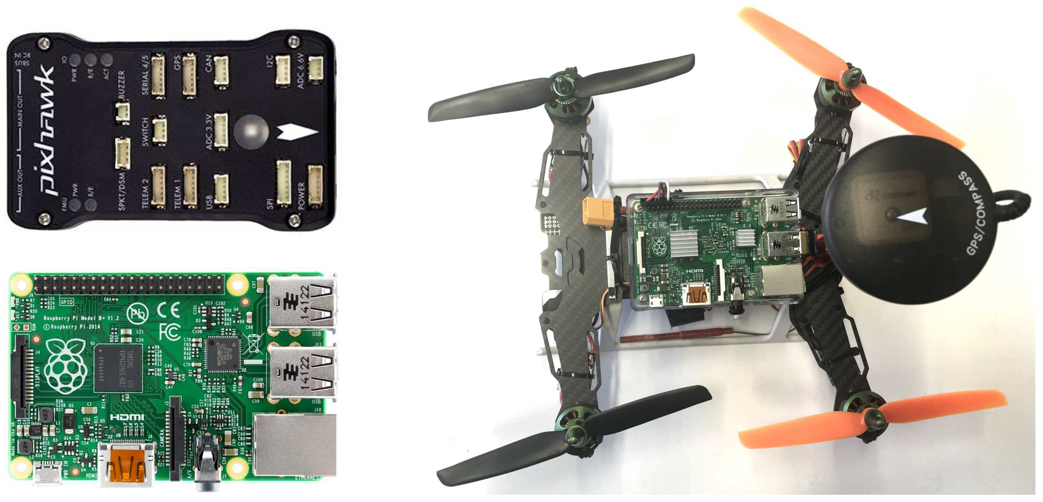
54], the onboard computing platform (running the control module (CM), the simulated mobile platform as well as the optional simulated sensor platform is a Raspberry Pi 2 (see
Figure 7) with the following specifications: a 900 MHz quad-core ARM Cortex-A7 CPU, 1GB RAM, 4 USB ports, 40 GPIO pins, Full HDMI port, Ethernet port, combined 3.5 mm audio jack and composite video, camera interface (CSI), display interface (DSI), Micro SD card slot, VideoCore IV 3D graphics core. It is running Linux (Raspbian) as operating system and ROS (BSD or LGPLv3 or GPLv3 License) over VPN to connect to other modules.
We used MAVROS to publish the autopilot’s/SITL’s mavlink data to the network, relay it to GCS (Ground Control Software) and relay the CM’s instructions to the autopilot. The Ardupilot SITL (SW in the loop, GPLv3 License, cf., for example, References [
55,
56,
57,
58,
59]) autopilot software facilitates the simulation of flight operations and enables us to use additional Raspberry Pis to simulate larger swarms.
3.1.2. Flight Module (FM)
The flight module (the hardware realizing all the flight operations, also used in, for example, References [
10,
54,
55]) is a Pixhawk (see
Figure 7) featuring a 168Mhz 32-Bit STM32F427 Cortex M4, 256KB RAM, 2MB Flash, 14 PWM/servo outputs as well as connectivity options for additional peripherals (UART, I2C, CAN) and redundant power supply inputs as well as an automatic failover. Regarding peripheral sensors we are currently using only GPS, Airspeed sensor, Sonar, LiDar and Optical Flow but the Pixhawk is not restricted to these and additional sensors can be added. The pixhawk is licensed under the Creative Commons License (Open-Source HW). We used APM Flight Stack (GPLv3 License). This connects to the navigation sensors (e.g., GPS) and controls all basic flight/navigation dynamics.
3.2. Simulation/Testing Environment
The process of designing and implementing distributed algorithms for the control of swarms poses the challenge of evaluating and testing them in the real world, that is, using actual hardware and letting it operate in a physical environment. UAV use and availability is spreading faster than awareness of—or legislative frameworks to address—related concerns [
16]. Their rapid adoption outpaces legal, policy and social ability to cope with issues regarding privacy and interference with well-established commercial air space [
60]. Regulations differ between countries [
13] and have to address a number of technical and societal concerns and challenges [
14]. Reference [
61] surveys the main security, privacy and safety aspects associated with the use of civilian drones in the national airspace.
By their nature (distributed and intended for swarms), the proposed algorithms require a substantial number of devices in order to show the intended benefit. The device type itself poses the problem of being subjected to a variety of different legal requirements depending on where (location) and under which circumstances (commercial, non-commercial, etc.) they are operated.
The demonstration platform currently under development will address these issues by (a) facilitating the use of large numbers of simulated devices to augment a small swarm of physical devices; and (b) enabling the co-location of physical devices that are factually not in the same place. While the latter makes it possible to share resources between different labs, it is primarily aimed at enabling us to perform demonstrations in areas where the legal restrictions for the operation of physical drones would otherwise prevent the demonstration (or make it exceedingly expensive).
Figure 8 shows the 4 components of the platform: (1) a control interface to run the simulation, (2) physical devices (possibly in a number of different locations), (3) simulated devices and finally (4) a visualization module showing the scenario.
We designed the platform to be able to handle a number of different devices, that is, it is not restricted to our quadcopters or, for that matter, to drones in general. Specifically the use with fixed-wing drones as well as rovers (unmanned ground vehicles) is possible and simulations could use all of these device types together.
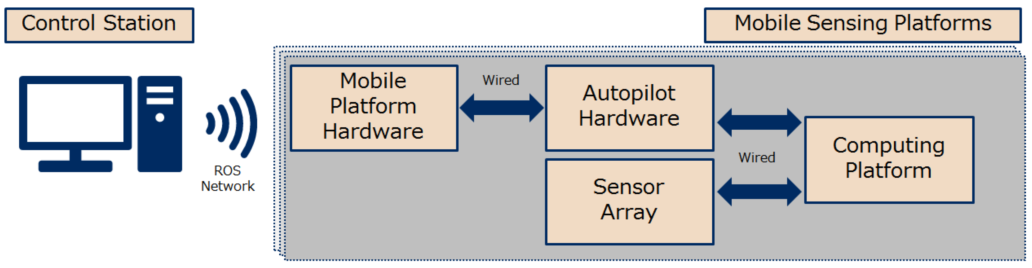
The current project only considers one type of drone but planning for this functionality already sets the stage for future projects that focus on inter-swarm collaboration and enables us to evaluate the performance of our algorithms in a broader context. The control unit as well as the visualization tool are realized in a control station (a PC or a laptop), which communicates through a wireless network with the members of the swarm (cf.
Figure 9). We do not distinguish between virtual and physical devices or even the device type (though in the foreseeable future we will only be using quadcopters) and call all of them
mobile sensing platforms (MSPs) as in
Figure 9. Within each MSP (of which there can be many) we distinguish between (a) the computing platform where the NEC proprietary algorithms are used (this is called
command module (CM) and with the exception of the flight module, all elements shown are part of the CM), (b) a sensor array (real or simulated), (c) the flight module (the hardware controlling the drone) and (d) the mobile hardware platform (i.e., the drone). The demonstration platform uses the ROS network as it provides all functionalities required for staging the demonstrations.
3.3. Implementation
The implementations required code for two physically separate parts of the demonstration platform: the control station (containing the Dispatch module) and UAV. For either algorithm implementation, the Dispatch module was the only module on the control station side for which code needed to be written (for the implementation of the algorithm; there was additional code written for the implementation of the System Control to handle, for example, UAV registry). On the UAV side, the only module that was concerned was the Computing Platform part of the MSP.
The control station is a laptop (running instances of Dispatch, Environment and System Control) while, as discussed, the Computing Platform on our UAVs was a Raspberry Pi 2.
3.3.1. Control Station Side (Dispatch Module)
On the control station side (in our case the laptop used to supervise the operations) only the Dispatch module is involved because this is where all altitude control relevant interaction between UAVs and the control station is happening. That is, any communication between the UAVs and the control station which is related to an ongoing swarm surveillance operation happens exclusively through the Dispatch, be it for general day-to-day or for dedicated and task specific operations.
For the altitude control algorithm we assume that the high level task of controlling the swarm is handled by a compartmentalized sub-system. Therefore, the implemented system allows UAVs to sign on as participating members (having been instructed to do so by another module sub-system of Dispatch) and constitutes the interface between the application side and the UAV swarm.
In a fully developed and deployed system Dispatch would also handle the data streams generated by the UAVs (e.g., video streams, coming from different UAVs and, together, covering all locations in the target area). Dispatch would combine these and pass them through to either the software analyzing the data or to the output device specified by the human operator.
3.3.2. UAV/Drone Side (MSP Control Module)
The UAV implementation can be implemented either in a centralized or a decentralized manner. Since the algorithm is inherently intended to be decentralized the choice is an operational and practical consideration: in the implementation of the simulation and demonstration platform (using ROS as communication framework) we found that the communication overhead was large because coordinating asynchronous communications between many different devices required a lot of time.
We implemented a centralized version of the approach where the code running on the laptop is coordinating the swarm: It performs all the calculations and periodically updates the swarm accordingly. However, this centralized version can also be implemented to run on one of the UAVs which then performs all the calculations and once a decision to re-allocate a location is made this “master drone” simply updates the swarm accordingly.
In the de-centralized approach, all UAVs compete for locations and interactions between UAVs are always between two UAVs that can both cover a specific location. Our decision to implement the algorithm in a centralized form was due to the inherent TCP/IP and wireless latency. A message round trip will take approx 20 ms which would mean that demonstrations would work slower than preferred. This is an issue that can be addressed by better or different communication architectures. We do not foresee any major obstacles when implementing the algorithm for a fleet of real UAVs. At the moment, the centralized implementation allows us to evaluate the approach without loss of generality.
3.3.3. Communication Protocols
The Dispatch module handles all issues related to communication with the swarm. UAVs sign on to a surveillance swarm and Dispatch supplies them with current and updated resolution requirements. The individual UAVs in return supply the Dispatch with a series of video streams (as well as an indication which areas these relate to).
4. Performance Evaluation
As pointed out above, the operation of a swarm of UAVs is subject to legal and operational constraints. The results reported in this section were created from operating a hybrid swarm, consisting of real as well as simulated drones (cf.
Figure 8). As shown in
Figure 9, all of our mobile sensing platforms (be it real physical devices or simulated drones) consists of a computing platform as well as (1) the mobile platform, (2) the sensor array and (3) the autopilot hardware. The computing platform is a Raspberry Pi 2 while the autopilot is a Pixhawk (both shown in
Figure 7). With the simulation capability of the Pixhawk (and since we did not actually use the sensor array in our evaluation of the algorithm) a simulated drone was, as far as the its subjective reality is concerned, indistinguishable from a real (physical) member of the swarm. This is because all instances of drones are realized within the Raspberry Pi, and therefore cannot distinguish between being connected to a Pixhawk-simulated devices and being onboard a real UAV (like the one shown in
Figure 7).
4.1. Setup
We operated a hybrid swarm of 25 devices (
) tasked with surveillance of an area consisting of 20 × 20 locations (
). The setup is shown in
Figure 10.
The altitudes of the drones were discretized, with the 11 altitudes ranging from zero (ground level) to 200 m, resulting in 10 altitudes that actually resulted in area coverage. The drones were operating at their maximum altitude (200 m) at the start of the simulation and locations were allocated randomly (in equal numbers) to the members of the swarm. The simulated devices were realize with at least 4 separate instances operating on a single Raspberry Pi (as opposed to the UAVs which operated on their own onboard Raspberry Pi). With regard to the (simulated) data generation, the swarm ignored zooming of cameras altogether and operated exclusively through changes in altitude. In addition, the swarm did not move in the x- or y-axis, effectively hovering over their assigned locations. For real-world deployment, we would assume the swarm to be in static positions and task another algorithm with the optimization of the x- and y-coordinates for each drone. Practically, the actual operation is assumed to use the zooming capability of the cameras to facilitate a quick change in resolution, which is then followed by a gradual change in the drones altitude.
The camera values used in the simulations are from a Sony NEX 5R camera with a 25 mm lens: pixels_h = 4592 (number of pixels in the Y axis of the sensor), pixels_v = 3056 (number of pixels in the X axis of the sensor), sensor_h = 23.4 (sensor size in the y axis), sensor_v = 15.6 (sensor size in the x axis). Therefore, as the horizontal resolution is marginally better than the vertical resolution we used the vertical ones to ensure we can deliver at least the reported quality. Along these lines, we simplified the area to be a square (not, as it really is, a rectangle) and ignored the additional area coverage.
4.2. Baseline Performance
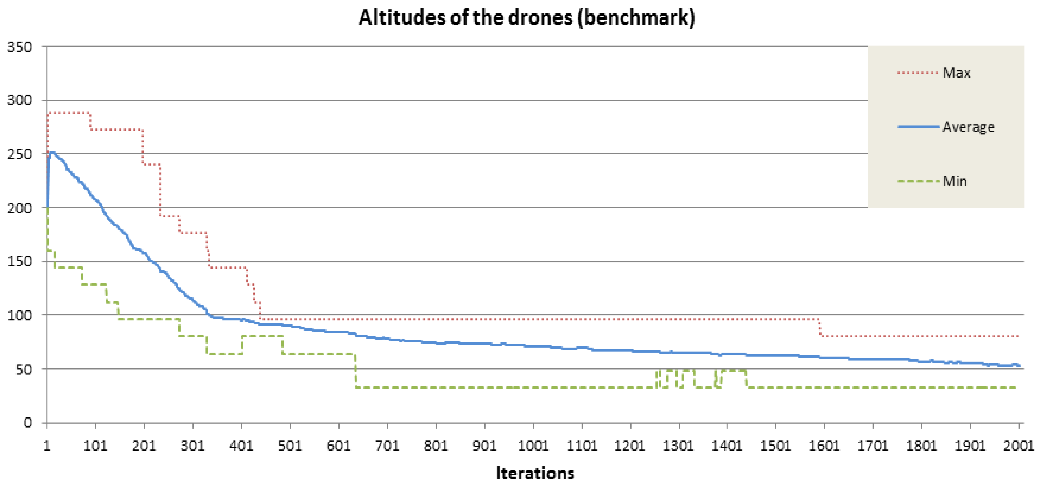
We first establish a baseline performance for the algorithm by using it to optimize the altitude of a swarm of UAVs in the absence of resolution requirements. Due to the homogenous distribution of the UAVs we know that the best possible solution is when all UAVs have descended to the altitude when they can cover two fields in any direction (i.e., an area of 4 × 4 locations). Given that the distribution of the UAVs allows for a unique best possible solution, we can test the convergence property of the algorithm. And indeed, the graphs in
Figure 11 show that the swarm converges quickly towards this solution within the first 2000 iterations. Due to the stochastic nature of the approach the swarm will only converge on very good solutions: even if the perfect allocation is found, it is not maintained as the drones continuously explore new allocations so as to further improve their performance.
As we reported in Reference [
19], in this specific evaluation scenario the swarm kept improving on its formation until shortly after iteration 6000, after which it basically maintained the optimal solution with the exception of brief deviations. One measure omitted in the results here is the standard deviation of the drones altitudes, which effectively dropped to zero after iteration 6000.
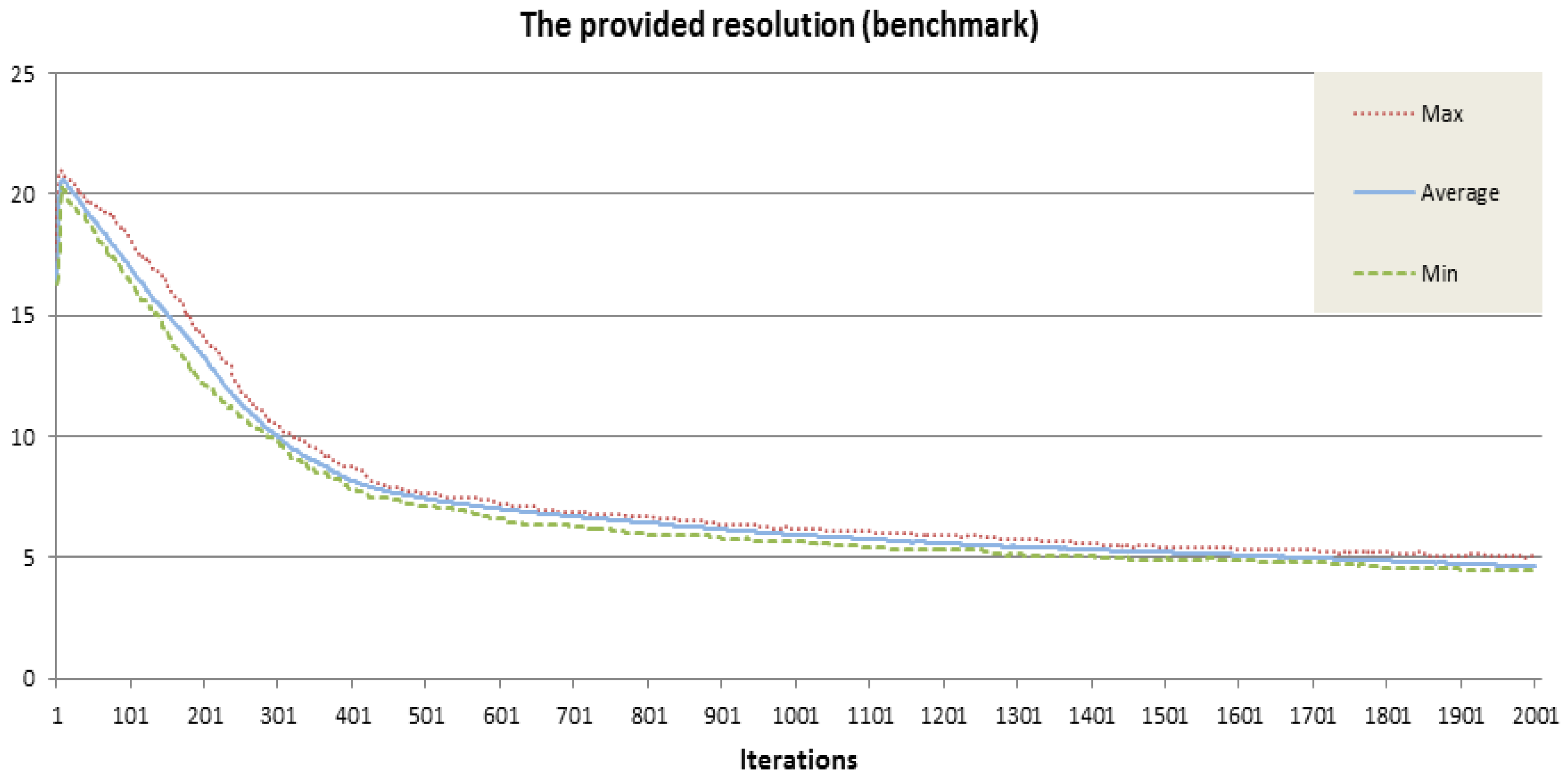
We argue that the results in
Figure 11 and
Figure 12 already show the merits of the approach, as the devices are finding the (obvious) best solution entirely through local optimization and without complete knowledge of the size and location of the swarm. In the following sections we will take a closer look at the performance of the algorithm when resolution requirements are added and removed, that is, for cases when the optimal solution is not as straight forward to find as in the baseline case.
4.3. Performance under Dynamic Requirement Changes
To test the performance of the algorithm when the resolution requirements are not uniformly distributed/the same everywhere we added specific resolution requirements during the simulation. The setup of the simulated surveillance task is shown and described in
Figure 10. In the baseline scenario above, all drones converged on the same altitude and into a stable formation (cf.
Figure 11). Under changing resolution requirements the optimal solution(s) are less stable and the occasional space exploration occur much more frequently (cf.
Figure 13).
Figure 14 shows the performance of the swarm. Shown are the aggregated outcomes of 15 separate simulations of the scenario described in
Figure 10. To indicate the consistent performance of the swarm we plot best, average and worst performance and point out that these differ marginally (which is to be expected considering that (a) the optimization process is stochastic and (b) that the approach has not been fine tuned to the specific problem specifications such as altitude and field of vision).
Notably, the swarm keeps improving on its performance despite requirements being added and changed. Specifically, the resolution requirements added at iteration 2000 and 6000 are identical, however the performance of the swarm is significantly better at 6000 iterations, when the continuing optimization has positioned the swarm better to react quickly and with less incurred penalty.
We do acknowledge the fact that the swarm fails to meet the requirements imposed at iteration 2000, however we point out that the solutions does consistently improve (as evidenced by the dropping
goodness value). The performance of the approach is directly related to the number of iterations, which in turn is linear in the incurred computational cost. Improving performance can be achieved through allocating more computational resources to enable the drones to cycle through more optimization attempts. In addition, the approach is not tuned to the specific parameters of the drones: tailoring the mathematical model to account for the allocation of neighbouring drones and the calculation of the penalty values (which directly influence the probability for exchanging locations, cf. Equation (
8)) will likely affect the convergence speed of the algorithm.
4.4. Simulating Massive Swarms
We close this section with a brief report on insights gained from simulating a massive swarm (400 devices). Throughout the paper we make the claim that one of the advantages of the approach is its scalability. The argument is that with communication and thus interaction limited to local interactions the communication incurred by any one devices is fixed (or at least dependent on the number of visible neighbours). Since devices are considered static in the x- and y-axis, their initial arrangement determines the neighbouring devices they can, individually, communicate and interact with.
There are many contributions in the literature that address the movement/flocking of devices [
49,
62,
63] and we argue that our approach can be seen as an extension of these approaches.
As long device interaction is limited by the devices’ ranges, then any additional devices added to the swarm that are added outside the range of a device will not affect the communication overhead incurred by that specific drone. Paraphrasing this, we could say that while the swarm size affects the communication cost of the approach linearly, the swarm
density can do so exponentially (with the upper bound of the density being centralized communication, resulting in exponential increase of communication bandwidth [
62] and software complexity [
64]).
To verify these assumptions and claims, we ran simulations on large swarms, consisting again of perfect lattice arrangements for 100, 144, 225, 324 and 400 drones (thus
,
,
,
and, as for the results shown in
Figure 15,
devices). In our simulation, a device communicates with only 8 neighbouring drones and the time to settle into the known best configuration we comparable to the time recorded for much smaller swarms, as was the evolution of the altitudes (shown in
Figure 11).
Further investigations into larger swarms are omitted because results from simulations are of limited academic use: given the setting of our simulation, the performance of larger swarms can now be inferred from the our results. Performance evaluation becomes increasingly difficult as the swarm is either subjected to an increasing number of not related tasks or left with a majority of the devices converging on the optimal configuration (cf.
Figure 15). With the current work and results in place, TNO is preparing to operate small swarms of 3 to 6 devices in real world settings and under outside weather conditions, using the hardware shown in
Figure 2.
We expect large swarms exceeding a dozen devices to be outside our practical reach for years to come and frankly, most applications currently considered are unlikely to be realized with larger numbers than that, due to legal and practical reasons and simply because it will be more efficient to trade time to solution versus cost of operating and maintaining (and transporting) the hardware.
5. The Road Ahead
Drones, albeit their almost pervasive presence (it is increasingly difficult to find someone who has not seen a drone operating in the wild), are still somewhat of a revolutionary technology in that their use and availability is spreading considerably faster than awareness about potential concerns or legislative frameworks to address these concerns [
16]. For the foreseeable future different countries will continue to impose different regulations regarding the use of UAVs [
13] and those regulations may be subject to frequent change and amendment. We expect that these
growing pains will be overcome in the years to come. Once there are solid regulations in place, the use of UAVs can become a regular and wide-spread practice. We believe that once that is the case, the benefits of operating swarms of devices will quickly become evident. This will lead to wide-spread use of swarming applications for autonomously operating devices.
The presented approach enables a swarm of devices to collaboratively cover an area and provide continuous data quality for, for example, video coverage, even if the resolution requirements for individual locations are subject to change. The approach is scalable and the swarm used for the evaluation is already large enough to deliver good results; performance will only increase with larger swarms. The success of the algorithm in real-world problems will depend critically on a good definition of device capabilities, task-properties and -synergies and these seem to be completely problem-dependent. Due to the mentioned legal and practical considerations the discussed evaluation is—in fact—merely a proof of concept. In the current legal climate the ongoing projects are mainly aiming at, for example, disaster response systems and other real world scenarios where normal regulations and norms are often suspended.


