Wing Design, Fabrication, and Analysis for an X-Wing Flapping-Wing Micro Air Vehicle


Abstract
:1. Introduction
2. Wing Design and Fabrication
2.1. Wing Sizing Method
2.1.1. Step 1—Defining the Flight Parameters
2.1.2. Step 2—Defining the Flight Modes
2.1.3. Step 3—Selecting the Wing Parameters
2.1.4. Step 4—Determining the Parameter of Wing Loading
2.1.5. Step 5—Estimating the Electrical and Structural Weights of FW-MAV
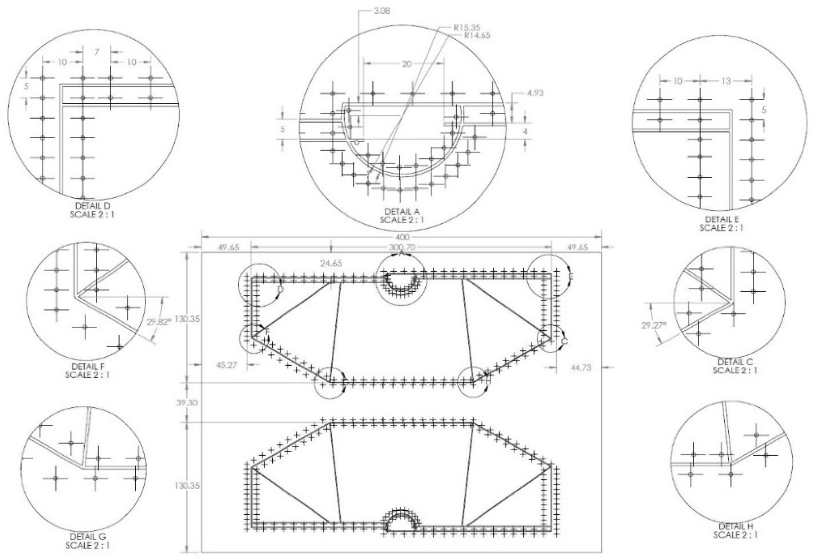
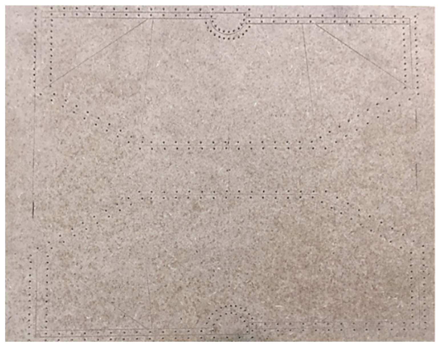
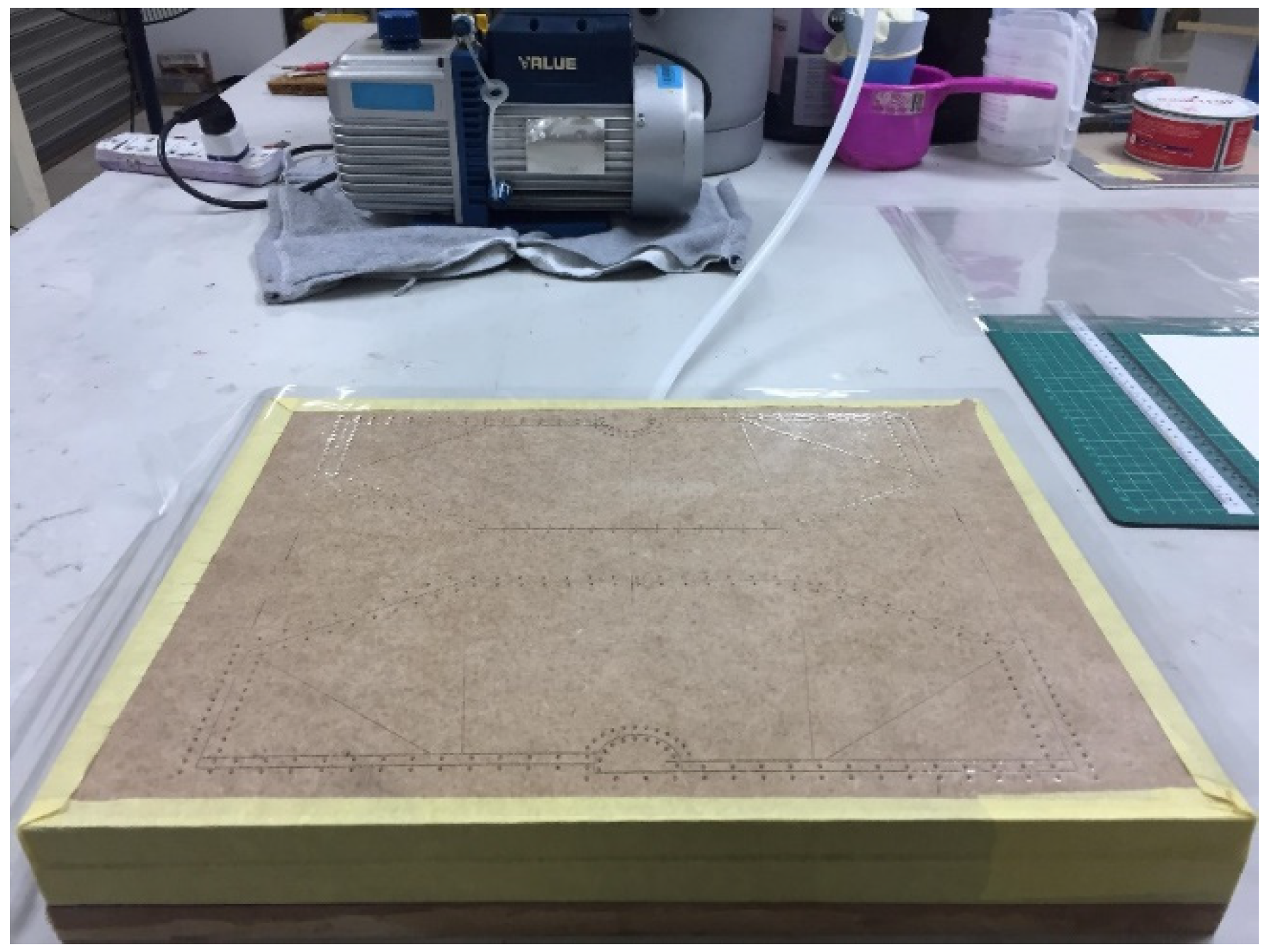
2.2. Wing Fabrication
2.2.1. Wing Materials
2.2.2. Wing Fabrication Using Traditional Method
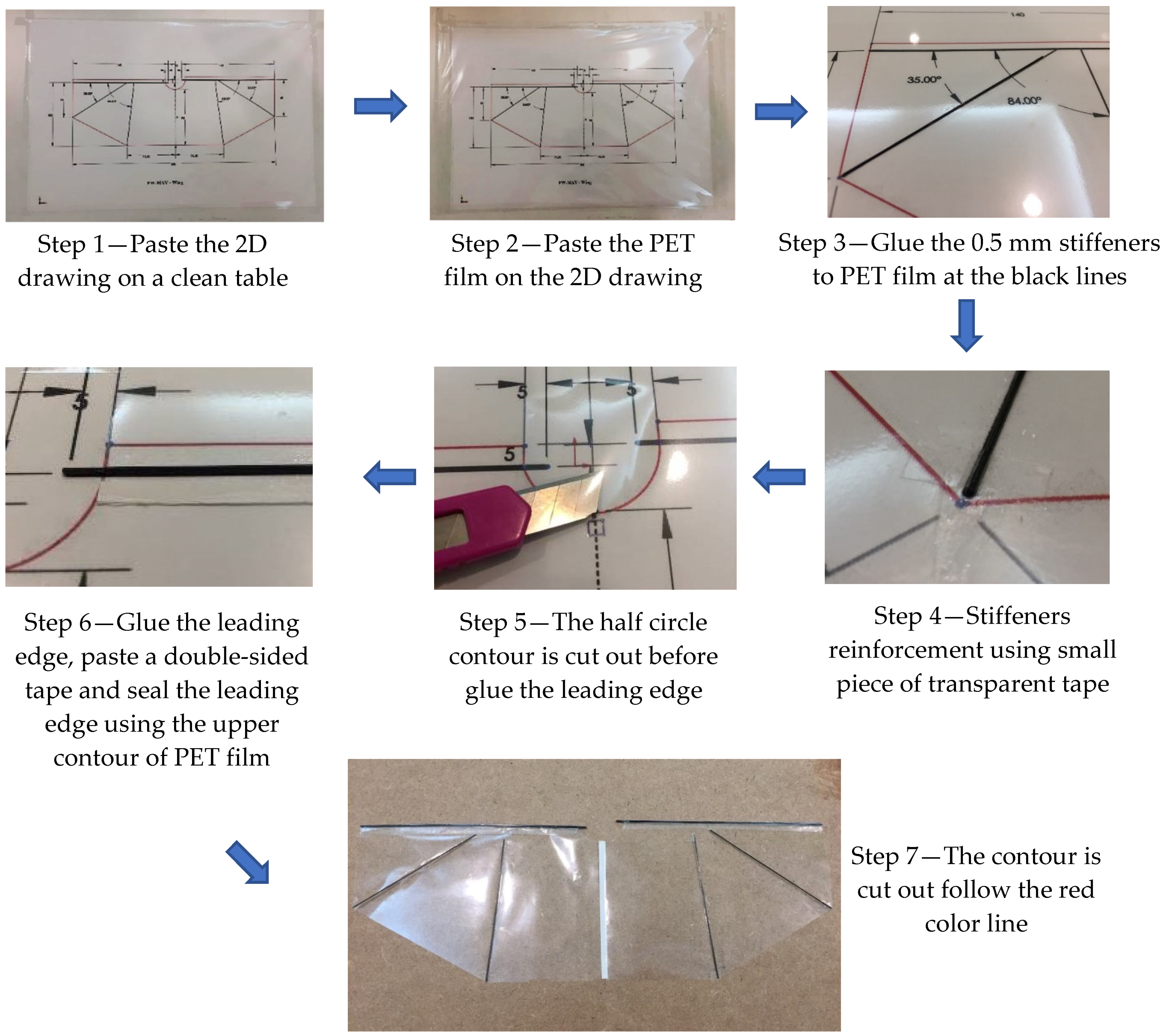
2.2.3. Wing Fabrication Using Advanced Method
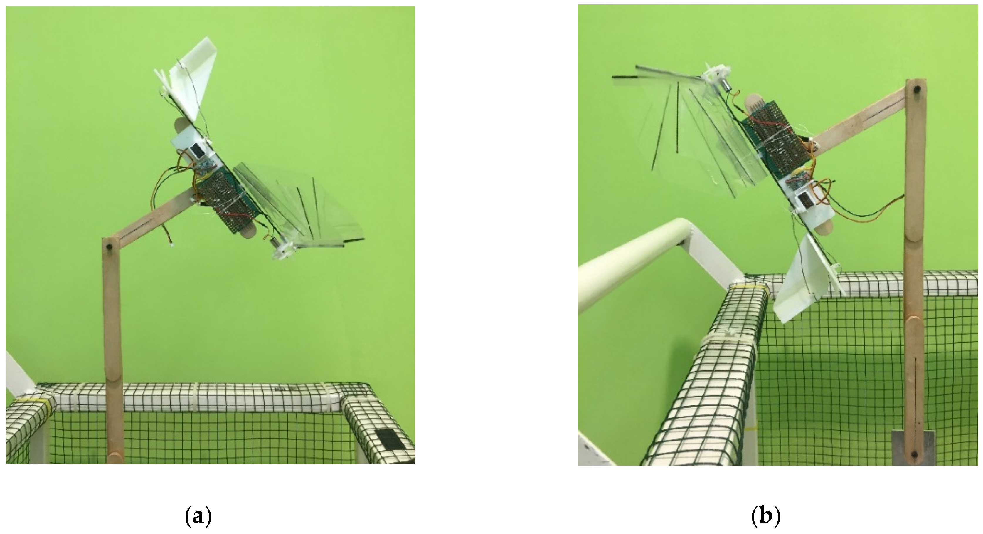
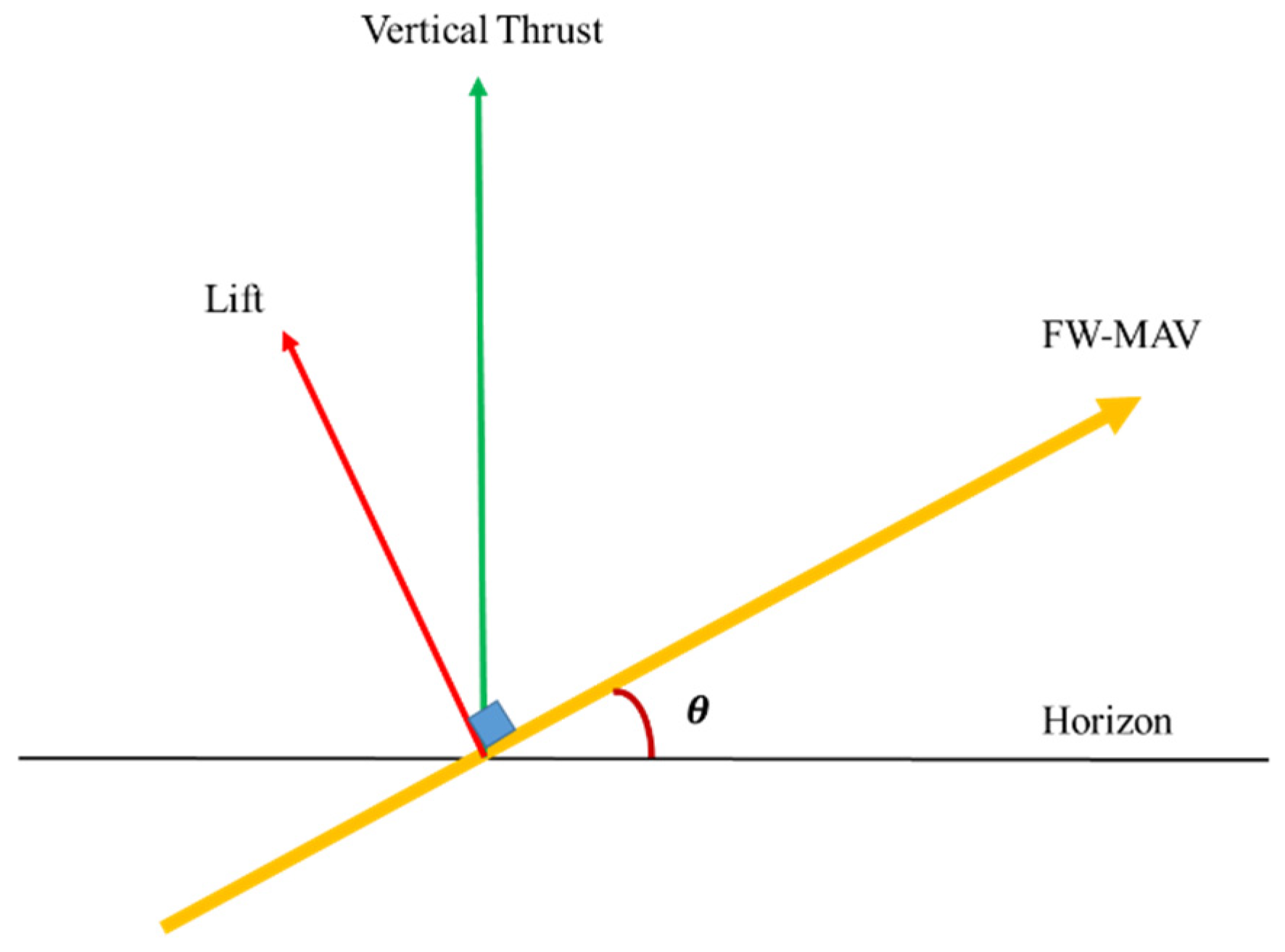
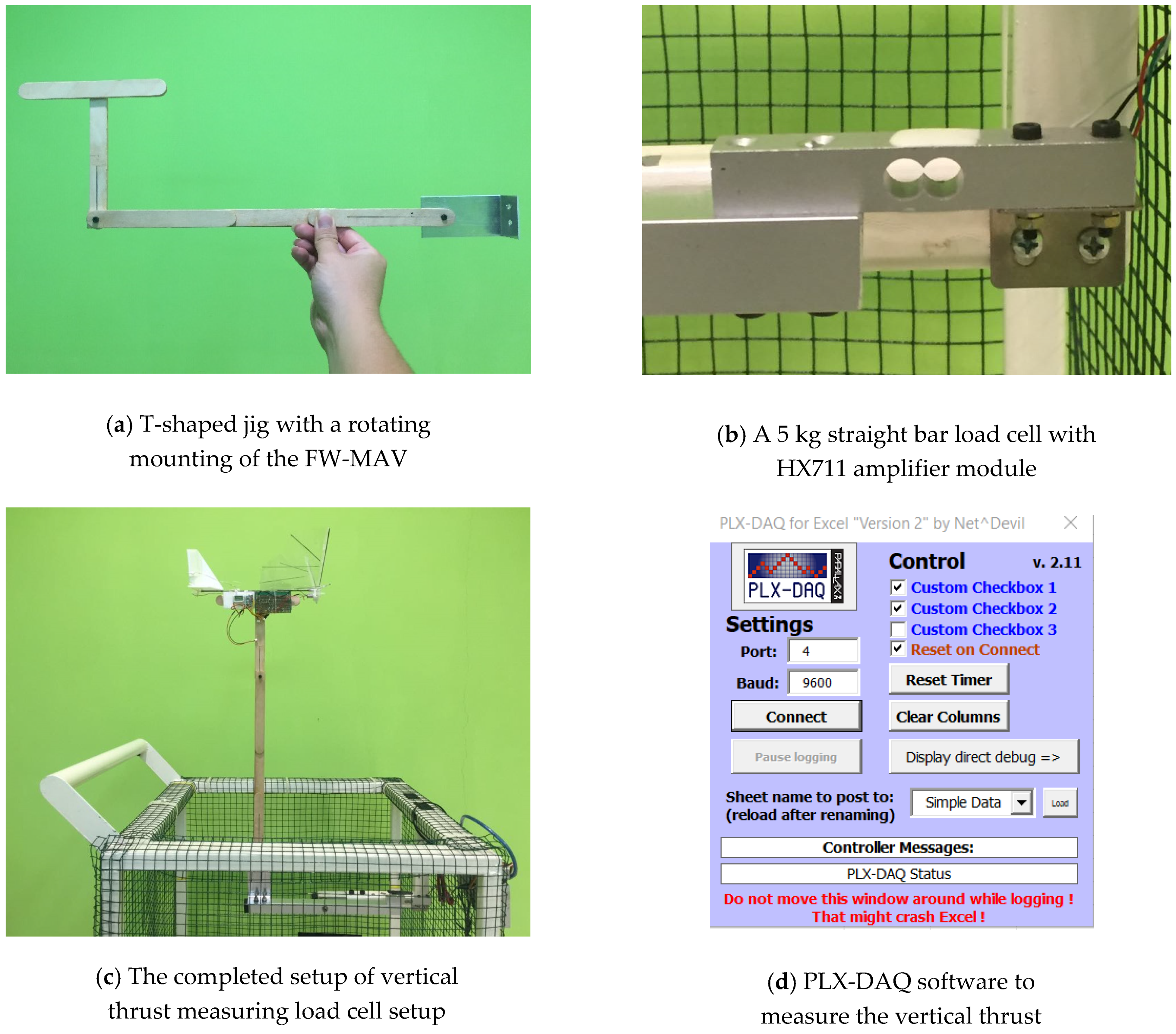
2.3. Vertical Thrust Measurement Setup
3. Results
3.1. Wing Sizing Result
3.1.1. Step 1—Defining the Mission
3.1.2. Step 4—Determining the Wing Loading
3.1.3. Step 5—Estimating the Electrical and Structural Weights of the FW-MAV
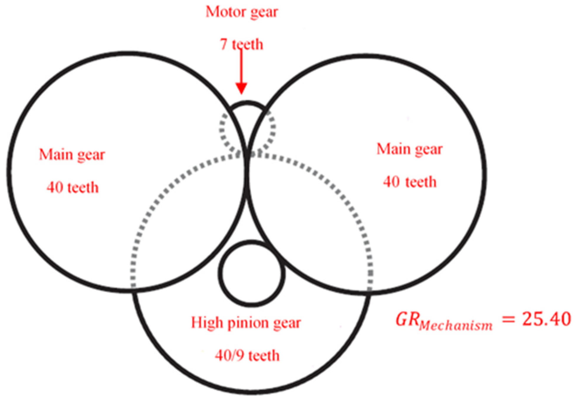
3.2. Gear Ratio and Flapping Frequencies
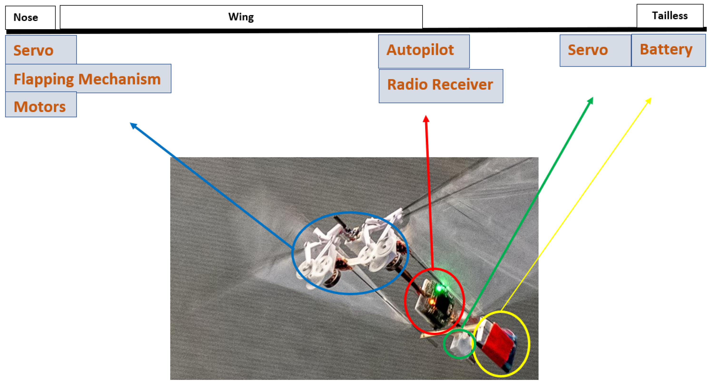
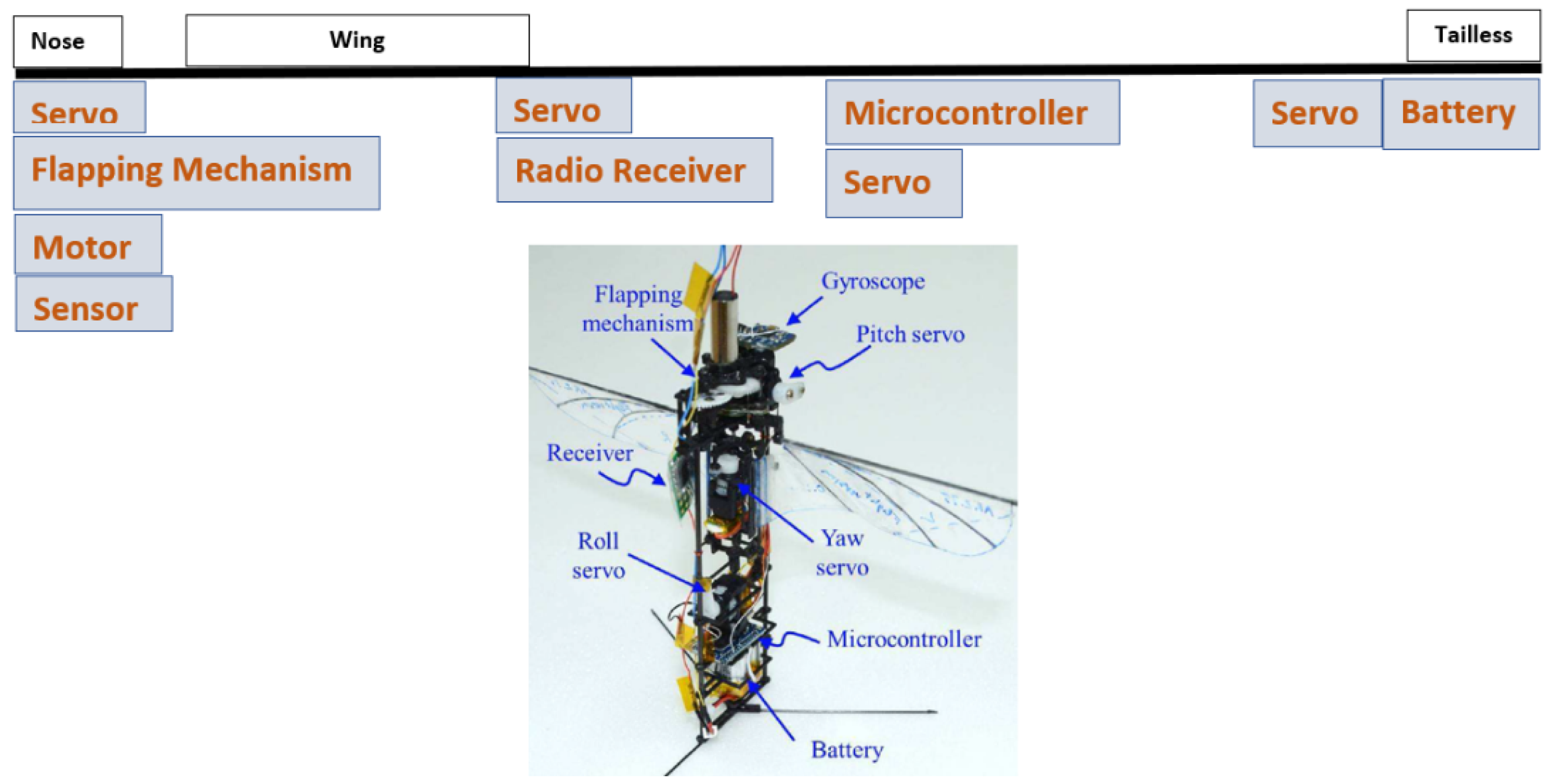
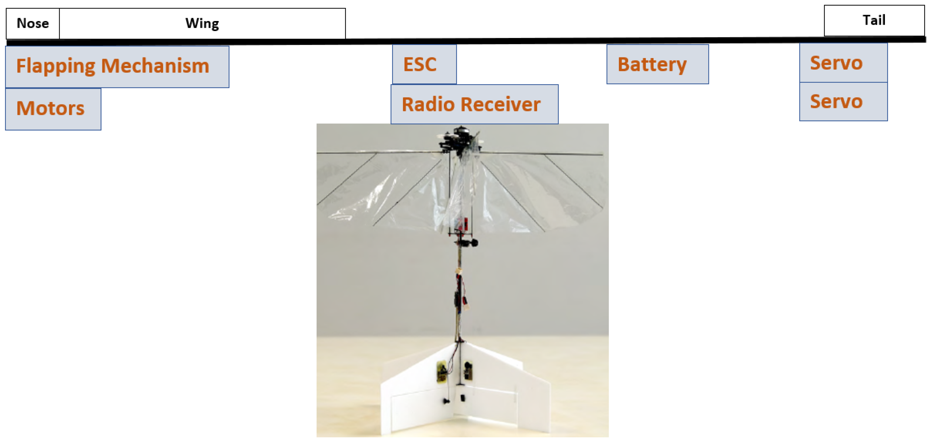
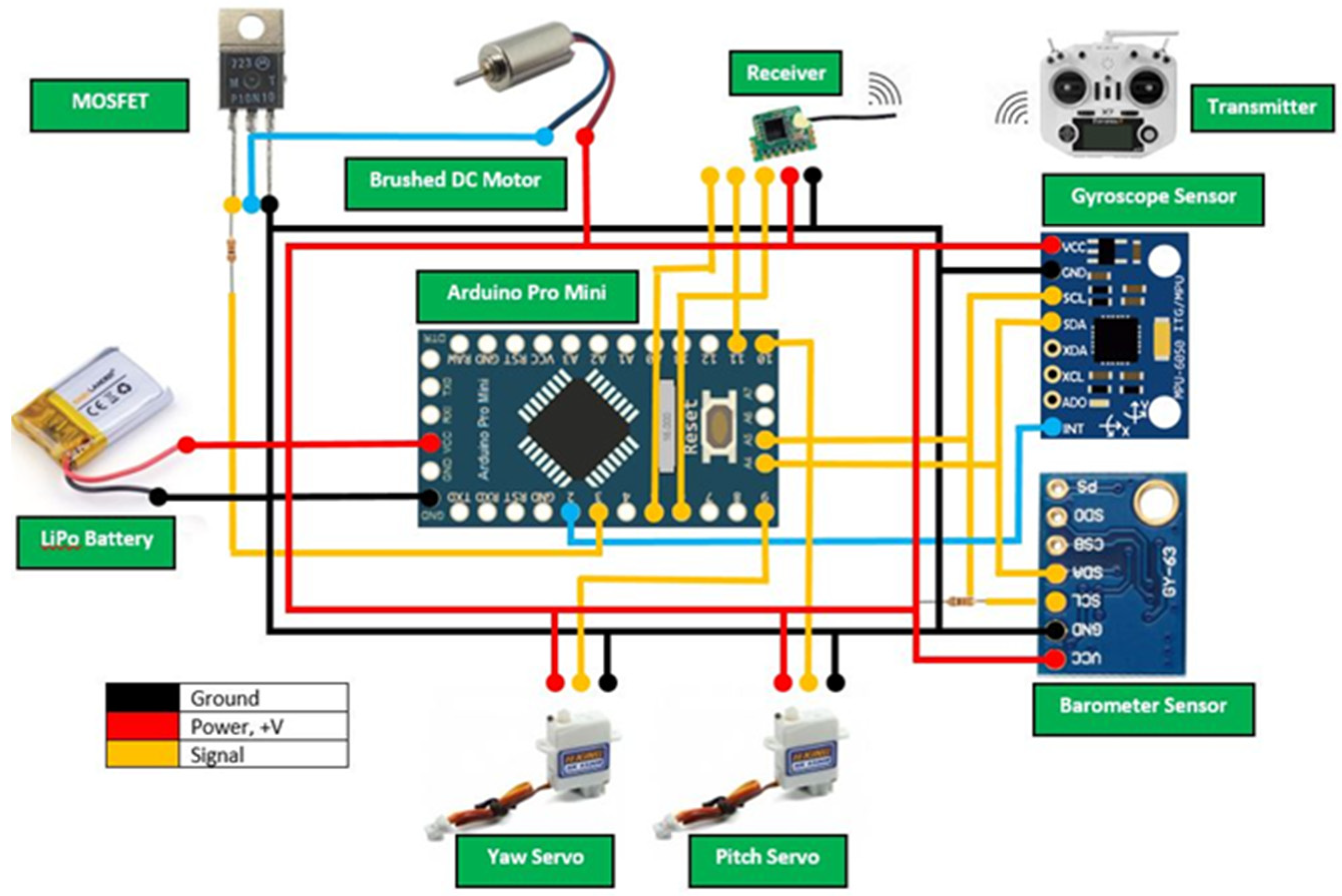
3.3. Avionic System
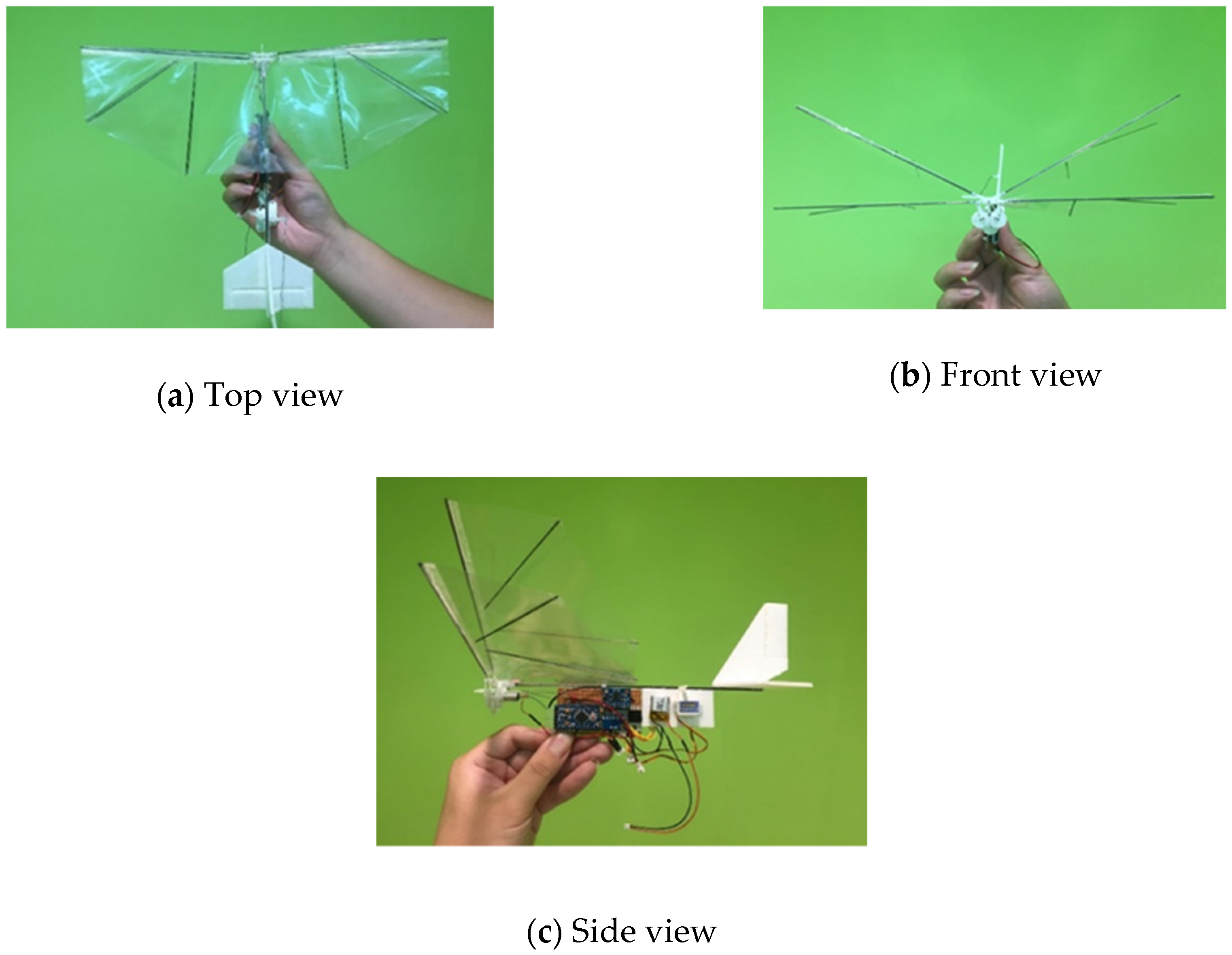
3.4. Fabricated Prototype
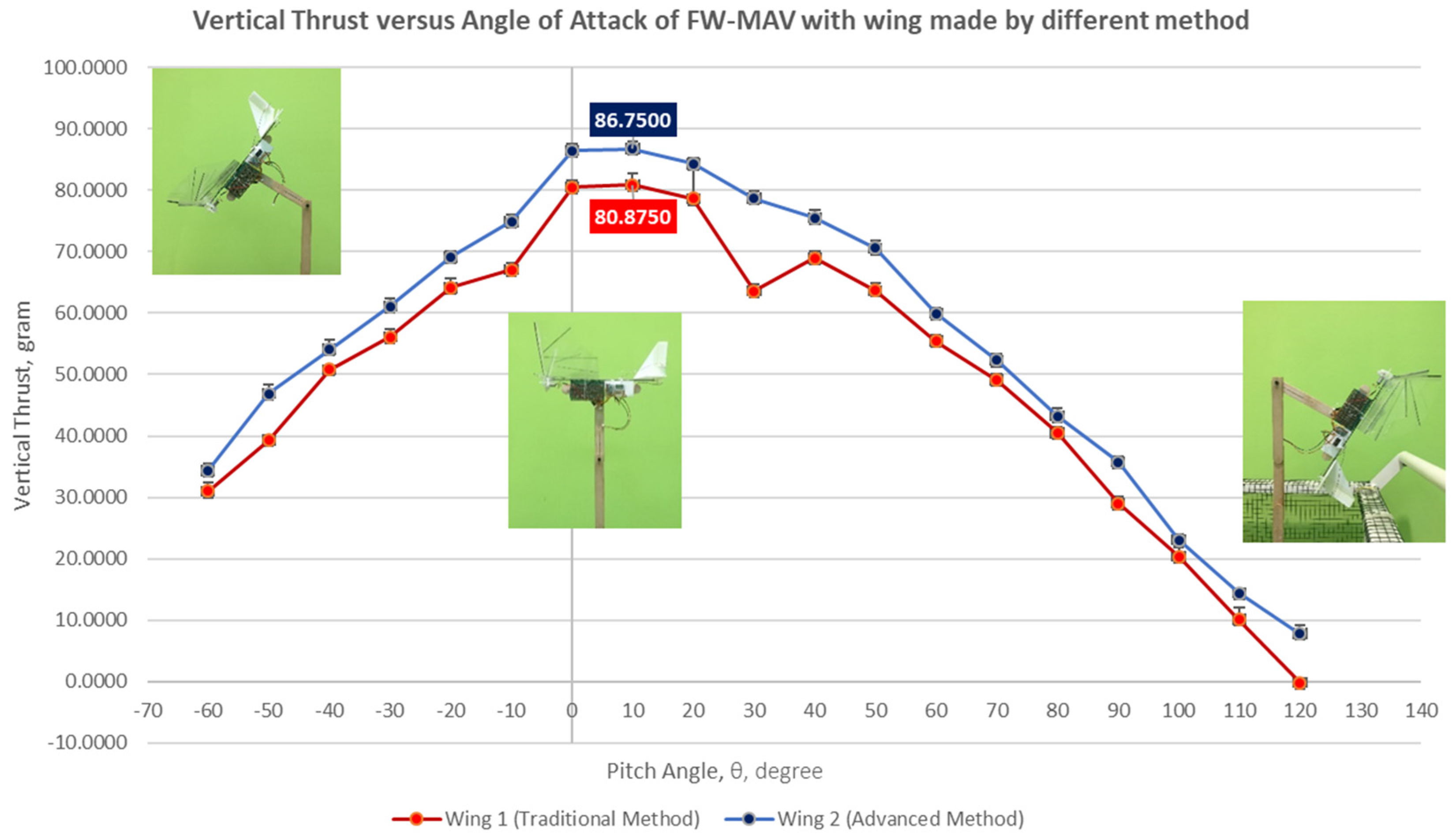
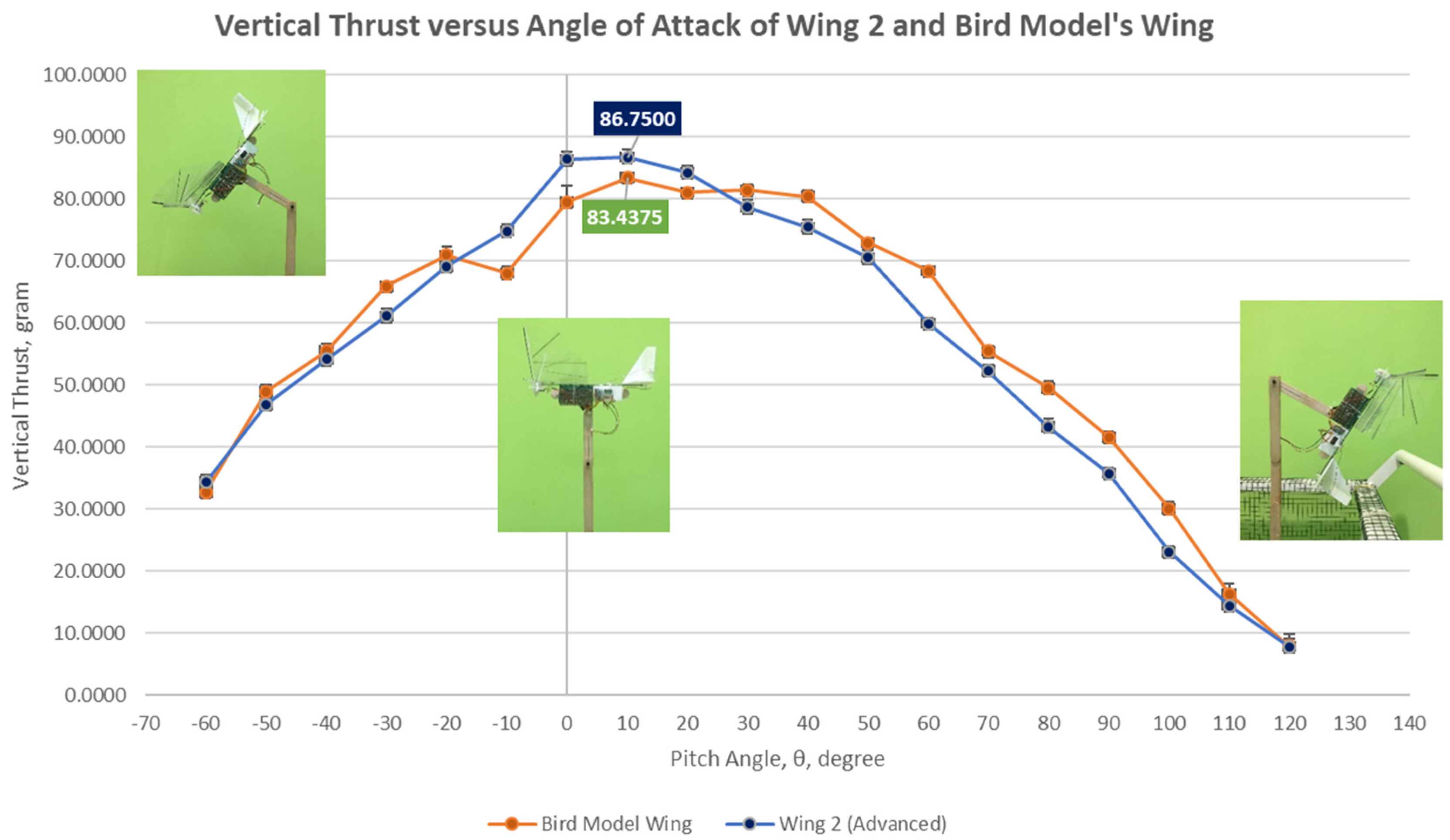
3.5. Vertical Thrust Measurement Result
4. Conclusions
Author Contributions
Acknowledgments
Conflicts of Interest
Appendix A

| Item | Parameter | Value |
|---|---|---|
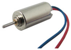 DC Micro Brushed Motor Function: to generate torque to flap the wing | Model | HW0001498 |
| Motor diameter | 6.0 mm | |
| Motor length | 14.0 mm | |
| Output shaft diameter | 0.8 mm | |
| Output shaft length | 5.0 mm | |
| Motor speed | 35,000 RPM | |
| Voltage | DC 3.7 V | |
| Current | 0.1 Amps | |
| Service life | 10,000 | |
| Mass | 1.87 grams | |
 Micro servos Function: to deflect the elevator and rudder | Model | HobbyKing™ HK-15318B |
| Mass | 3.4 g | |
| Size | 8* 20* 23 mm | |
| Operating Speed | 0.09 s/60 degrees | |
| Stall Torque | 0.10 kg/cm | |
| Operating Voltage | 2.8 V~4.2 V | |
| Battery | 1S capable | |
| Plug | JST .25 Pitch | |
 LiPo Battery Function: to provide power source | Model | LiPo Rechargeable Battery |
| Capacity | 70 mAh | |
| Voltage | 3.7 V | |
| Cycle life | 500~700 cycles | |
| Mass | 2.43 g (including wire) | |
| Dimensions | 4.0* 14* 20 mm | |
| Balance Plug | JST | |
 MOSFET Function: to regulate voltage | Model | IRFZ44N Power MOSFET |
| Type | N – Channel | |
| Maximum Drain-Source | 55.0 V | |
| Maximum Gate-Source | 10.0 V | |
| Maximum Gate-Threshold | 4.0 V | |
| Mass | 2.11 g | |
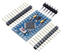 Arduino Pro Mini Function: to process input and sensor signals and send output signals and serve as the autopilot | Model | ATmega328 |
| Operating Voltage | 3.3 V | |
| Board Power Supply | 3.35 V~12.0 V | |
| Maximum current drawn | 200 mA | |
| PWM Pins | 6 | |
| Analog Input Pins | 6 | |
| Flash Memory | 32 Kbytes | |
| Clock Speed | 8 MHz | |
| I2C | 1 | |
| PWM Pins | 6 | |
| Dimension | 18 mm * 33 mm | |
| Mass | 4.62 g (includes pin headers) | |
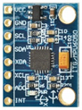 Gyroscope + Accelerometer Sensor Function: to measure rotational rates and linear accelerations | Model | GY-521 3-axis 6 DOF Modules |
| Chip | MPU-6050 | |
| Operating Voltage | 3.0 V~5.0 V | |
| Dimensions | 20.3 mm* 15.6 mm | |
| Mass | 1.60 g | |
| Gyroscope range | + 250 500 1000 2000 degree/s | |
| Acceleration range | ± 2 ± 4 ± 8 ± 16 g | |
| Communication | I2C | |
| Pin Pitch | 2.54 mm | |
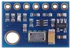 Atmospheric Height Sensor Function: to measure the altitude | Model | MS5611 Barometric Module |
| Chip | MS5611 | |
| Operating Voltage | 3.0 V~5.0 V | |
| Dimensions | 19 mm* 13 mm | |
| Mass | 1.30 g | |
| Operating temperature | −40~+85 °C | |
| Communication | I2C/SPI | |
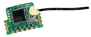 Receiver Function: to communicate with the transmitter | Model | FrSky XMR micro receiver |
| Frequency band | 2.4 GHz | |
| Mass | 0.8 g | |
| Operating Current | 20 mA @ 5.0 V | |
| Operating Voltage | 3.5 V~10.0 V | |
| Operating Range | 300 m | |
| Number of Channels | 1~6 channel | |
| Dimension | 15* 14* 3.5 mm | |
| Weight | 0.74 g | |
| Compatibility | Transmitter D16 modules mode | |
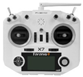 Transmitter Function: to communicate with the receiver | Model | Taranis Q-X7 |
| Frequency band | 2.4~2.4835 GHz | |
| Number of Channels | 16~32 channels | |
| Operating Temperature | −10~60 °C | |
| Operating Current | 210 mA | |
| Operating voltage | 6.0 V~15.0 V | |
| Flash Memory | 16 MB |
References
- Mwongera, V.M. A review of Flapping Wing MAV modelling. Int. J. Aeronaut. Sci. Aerosp. Res. 2015, 2, 27–36. [Google Scholar]
- Tang, J.; Sun, J.; Lu, C.; Lao, S. Optimized artificial potential field algorithm to multi-unmanned aerial vehicle coordinated trajectory planning and collision avoidance in three-dimensional environment. Proc. Inst. Mech. Eng. Part G J. Aerosp. Eng. 2019. [Google Scholar] [CrossRef]
- D’Andrea, R. Guest editorial can drones deliver? IEEE Trans. Autom. Sci. Eng. 2014, 11, 647–648. [Google Scholar] [CrossRef]
- Nakata, T.; Liu, H.; Tanaka, Y.; Nishihashi, N.; Wang, X.; Sato, A. Aerodynamics of a bio-inspired flexible flapping-wing micro air vehicle. Bioinspir. Biomim. 2011, 6, 045002. [Google Scholar] [CrossRef] [PubMed]
- Armanini, S.F.; De Visser, C.C.; De Croon, G.C.H.E.; Mulder, M. Time-varying model identification of flapping-wing vehicle dynamics using flight data. J. Guid. Control Dyn. 2015, 38, 526–541. [Google Scholar] [CrossRef]
- Armanini, S.F.; Caetano, J.V.; De Croon, G.C.H.E.; De Visser, C.C.; Mulder, M. Quasi-steady aerodynamic model of clap-and-fling flapping MAV and validation using free-flight data. Bioinspir. Biomim. 2016, 11, 046002. [Google Scholar] [CrossRef] [PubMed] [Green Version]
- Shyy, W.; Aono, H.; Kang, C.K.; Liu, H. An Introduction to Flapping Wing Aerodynamics; Cambridge University Press: New York, NY, USA, 2013; Volume 37. [Google Scholar]
- Weis-Fogh, T. Quick estimates of flight fitness in hovering animals, including novel mechanisms for lift production. J. Exp. Biol. 1973, 59, 169–230. [Google Scholar]
- Ellington, C.P.; Van Den Berg, C.; Willmott, A.P.; Thomas, A.L. Leading-edge vortices in insect flight. Nature 1996, 384, 626. [Google Scholar] [CrossRef]
- Dickinson, M.H.; Lehmann, F.O.; Sane, S.P. Wing rotation and the aerodynamic basis of insect flight. Science 1999, 284, 1954–1960. [Google Scholar] [CrossRef] [PubMed]
- Sane, S.P. The aerodynamics of insect flight. J. Exp. Biol. 2003, 206, 4191–4208. [Google Scholar] [CrossRef] [PubMed] [Green Version]
- Wood, R.J. The first takeoff of a biologically inspired at-scale robotic insect. IEEE Trans. Robot. 2008, 24, 341–347. [Google Scholar] [CrossRef]
- Pister, K.S.; Judy, M.W.; Burgett, S.R.; Fearing, R.S. Microfabricated hinges. Sens. Actuators A Phys. 1992, 33, 249–256. [Google Scholar] [CrossRef]
- Trimmer, W.S. Microrobots and micromechanical systems. Sens. Actuators 1989, 19, 267–287. [Google Scholar] [CrossRef]
- Keennon, M.; Klingebiel, K.; Won, H.; Andriukov, A. Development of the Nano Hummingbird: A tailless flapping wing micro air vehicle. In Proceedings of the 50th AIAA Aerospace Sciences Meeting Including the New Horizons Forum and Aerospace Exposition, Nashville, TN, USA, 9–12 January 2012; pp. 1–17. [Google Scholar]
- Phan, H.V.; Kang, T.; Park, H.C. Design and stable flight of a 21 g insect-like tailless flapping wing micro air vehicle with angular rates feedback control. Bioinspir. Biomim. 2017, 12, 036006. [Google Scholar] [CrossRef] [PubMed]
- Groen, M.; Bruggeman, B.; Remes, B.; Ruijsink, R.; Van Oudheusden, B.W.; Bijl, H. Improving flight performance of the flapping wing MAV DelFly II. In Proceedings of the Int. Micro Air Vehicle Conf. and Competition (IMAV 2010), Braunschweig, Germany, 6–8 July 2010. [Google Scholar]
- Karásek, M.; Muijres, F.T.; De Wagter, C.; Remes, B.D.; de Croon, G.C. A tailless aerial robotic flapper reveals that flies use torque coupling in rapid banked turns. Science 2018, 361, 1089–1094. [Google Scholar] [CrossRef] [PubMed] [Green Version]
- Nguyen, Q.V.; Chan, W.L.; Debiasi, M. Experimental investigation of wing flexibility on force generation of a hovering flapping wing micro air vehicle with double wing clap-and-fling effects. Int. J. Micro Air Veh. 2017, 9, 187–197. [Google Scholar] [CrossRef]
- Phan, H.V.; Park, H.C. Design and evaluation of a deformable wing configuration for economical hovering flight of an insect-like tailless flying robot. Bioinspir. Biomim. 2018, 13, 036009. [Google Scholar] [CrossRef] [PubMed]
- Nan, Y.; Karásek, M.; Lalami, M.E.; Preumont, A. Experimental optimization of wing shape for a hummingbird-like flapping wing micro air vehicle. Bioinspir. Biomim. 2017, 12, 026010. [Google Scholar] [CrossRef] [PubMed]
- Bruggeman, B. Improving Flight Performance of DelFly II in Hover by Improving Wing Design and Driving Mechanism. Master’s Thesis, Delft University of Technology, Delft, The Nederland, 2010. [Google Scholar]
- Yang, W.; Wang, L.; Song, B. Dove: A biomimetic flapping-wing micro air vehicle. Int. J. Micro Air Veh. 2018, 10, 70–84. [Google Scholar] [CrossRef]
- Nam, T. A generalized sizing method for revolutionary concepts under probabilistic design constraints. Ph.D. Thesis, Georgia Institute of Technology, Atlanta, GA, USA, 2007. [Google Scholar]
- Silin, D. Aerodynamics and Flight Performance of Flapping Wing Micro Air Vehicles. Ph.D. Thesis, University of Arizona, Tucson, AZ, USA, 2010. [Google Scholar]
- Hassanalian, M.; Abdelkefi, A. Methodologies for weight estimation of fixed and flapping wing micro air vehicles. Meccanica 2017, 52, 2047–2068. [Google Scholar] [CrossRef]
- FW-MAV Tethered Flight Test. Available online: https://youtu.be/qfACJa0LJOc (accessed on 2 August 2019).


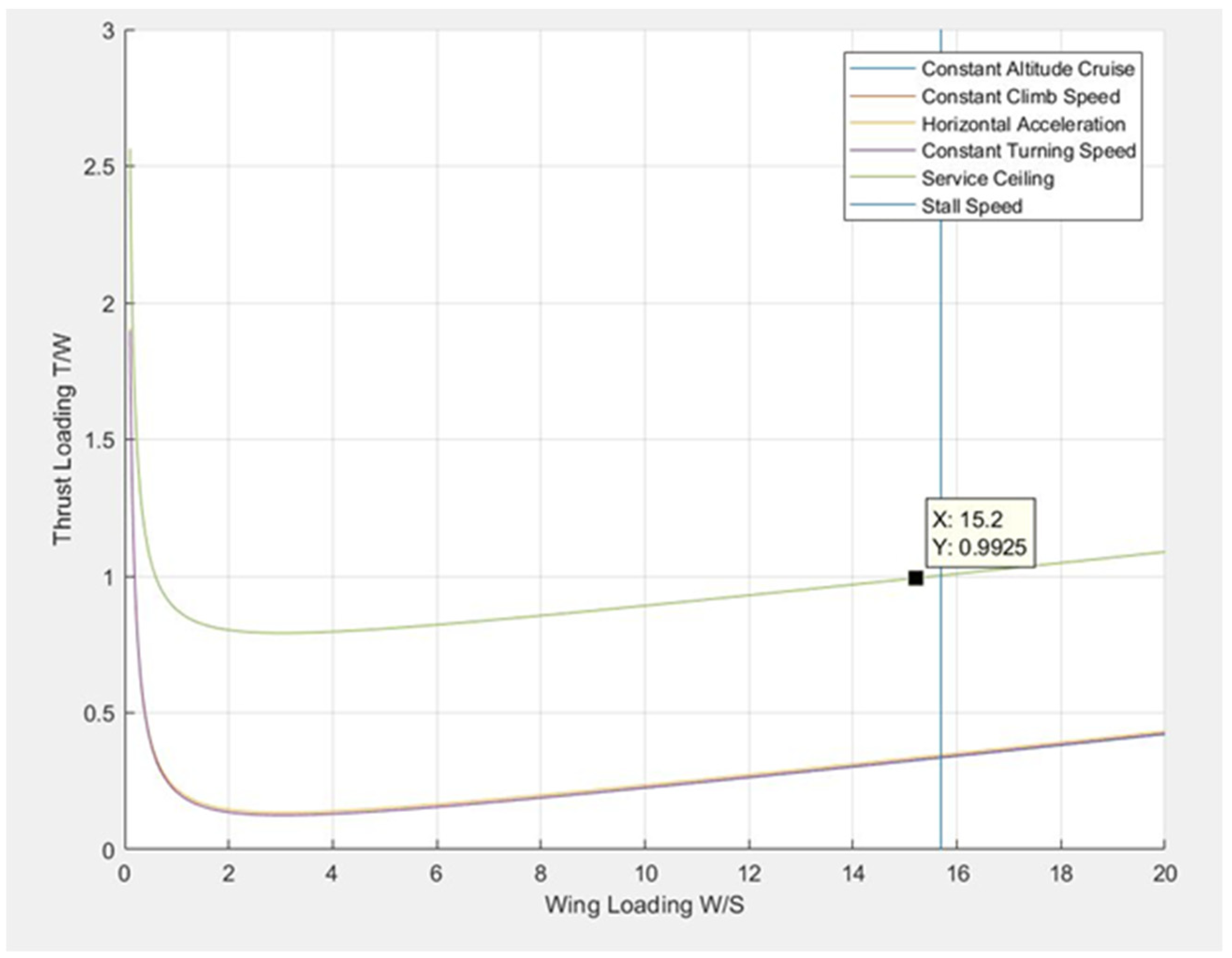

| Flight Condition | Equation | |
|---|---|---|
| Case 1—Constant Altitude/ Speed Cruise | (2) | |
| Case 2—Constant Climb Speed | (3) | |
| Case 3—Horizontal Acceleration | (4) | |
| Case 4—Sustained turn/ Constant turning altitude | (5) | |
| Case 5—Service Ceiling/ Accelerated Climb | (6) | |
| Case 6—Hand Launch Stall Speed | (7) |
| Weight Range (g) | |||||
|---|---|---|---|---|---|
| <100 | 23 | 2 | 24 | 13 | 38 |
| 100–400 | 16 | 1 | 14 | 9 | 60 |
| 400–800 | 12 | 0 | 12 | 4 | 72 |
| Picture | Name | Dimensions | Amount |
|---|---|---|---|
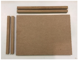 | MDF Board | 30.0 cm × 40.0 cm | 2 |
| MDF Bar (Long) | 38.2 cm × 2.0 cm | 2 | |
| MDF Bar (Short) | 28.2 cm × 2.0 cm | 2 |
| Parameter | Symbol | Value |
|---|---|---|
| Acceleration of gravity () | 9.78 | |
| Air Temperature () | 14.98 | |
| Air Density () | 1.226 | |
| Kinematic viscosity () | 0.9452 | |
| Air Pressure () | 1012.639 |
| Variable | Value | Variable | Value |
|---|---|---|---|
| 0.999912229 | 2.4 | ||
| 0.1137 | 0.007156 | ||
| 0.8 | 0.8 | ||
| 5.517 | 0.1 |
| Electric components used in FW-MAV | Category | Name | Weight, g |
| 3.7 V, 70 mAh, 15 C Lithium Polymer battery | 2.43 | ||
| MPU6050 sensor | 1.60 | ||
| MS5611 Pressure sensor | 1.30 | ||
| Additional weight for payload such as micro SD breakout board or camera for future use. | 3.00 | ||
| Avionics, | Arduino Pro Mini328 3.3 V MHz | 4.62 | |
| HK-15318B Micro Servo × 2 | 3.40 × 2 | ||
| FrSky XMR Micro Receiver | 0.80 | ||
| HW0001498 DC Motor | 1.87 | ||
| MOSFET IRFZ44N | 2.11 | ||
| 1k ohm resistor × 3 | 0.11 × 3 |
| Weight | Values |
|---|---|
| Weight of Electrical Components, | 24.86 g |
| Weight of structure, | 15.23 g |
| Total Weight, | 40.097 g |
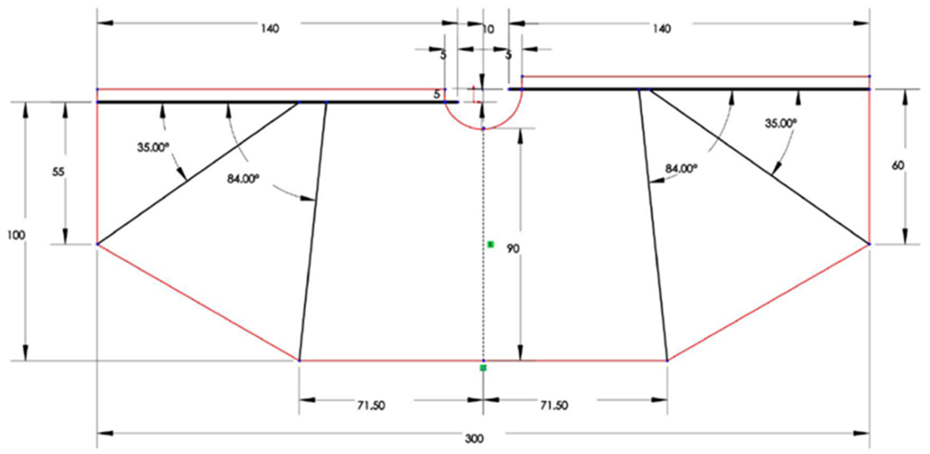
| Wing Sizing Parameters | Values |
|---|---|
| Total Wing Area, | 25,796 mm2 |
| Wing Aspect Ratio, | 3.50 |
| Wingspan, | 300.48 mm |
| Taper Ratio, | 0.55 |
| Wing tip chord length, | 55 mm |
| Wing root chord length, | 100 mm |
| Wings | Dimensions | Mass | Shape | Stiffeners |
|---|---|---|---|---|
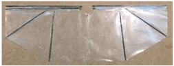 Wing 1 (Traditional Method) | 30.0 cm × 10.5 cm | 2.81 g | Trapezoidal | Yes |
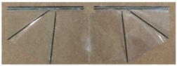 Wing 2 (Advanced Method) | 30.0 cm × 10.5 cm | 2.87 g | Trapezoidal | Yes |
 Bird Model Wing | 28.0 cm × 9.5 cm | 1.68 g | Elliptical | No |
© 2019 by the authors. Licensee MDPI, Basel, Switzerland. This article is an open access article distributed under the terms and conditions of the Creative Commons Attribution (CC BY) license (http://creativecommons.org/licenses/by/4.0/).
Share and Cite
Cheaw, B.H.; Ho, H.W.; Abu Bakar, E. Wing Design, Fabrication, and Analysis for an X-Wing Flapping-Wing Micro Air Vehicle. Drones 2019, 3, 65. https://doi.org/10.3390/drones3030065
Cheaw BH, Ho HW, Abu Bakar E. Wing Design, Fabrication, and Analysis for an X-Wing Flapping-Wing Micro Air Vehicle. Drones. 2019; 3(3):65. https://doi.org/10.3390/drones3030065
Chicago/Turabian StyleCheaw, Boon Hong, Hann Woei Ho, and Elmi Abu Bakar. 2019. "Wing Design, Fabrication, and Analysis for an X-Wing Flapping-Wing Micro Air Vehicle" Drones 3, no. 3: 65. https://doi.org/10.3390/drones3030065
APA StyleCheaw, B. H., Ho, H. W., & Abu Bakar, E. (2019). Wing Design, Fabrication, and Analysis for an X-Wing Flapping-Wing Micro Air Vehicle. Drones, 3(3), 65. https://doi.org/10.3390/drones3030065