
Structure Design and Event-Triggered Control of a Modular Omnidirectional Mobile Chassis of Life Support Robotics


Abstract
1. Introduction
2. Novel Omnidirectional Mobile Chassis
2.1. Principle Analysis of Omnidirectional Movement
- Along the wheel forward direction:
- Along the wheel axis direction:
2.2. Structure of Omnidirectional Mobile Chassis
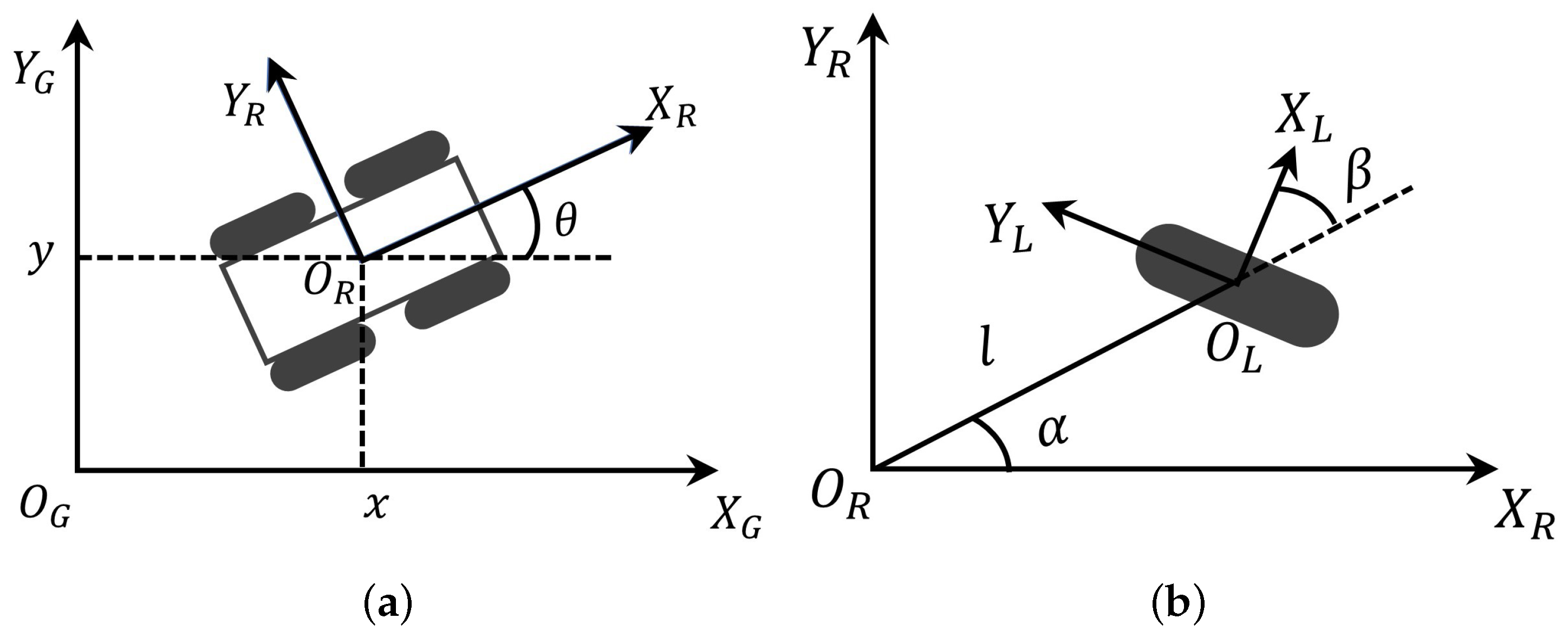
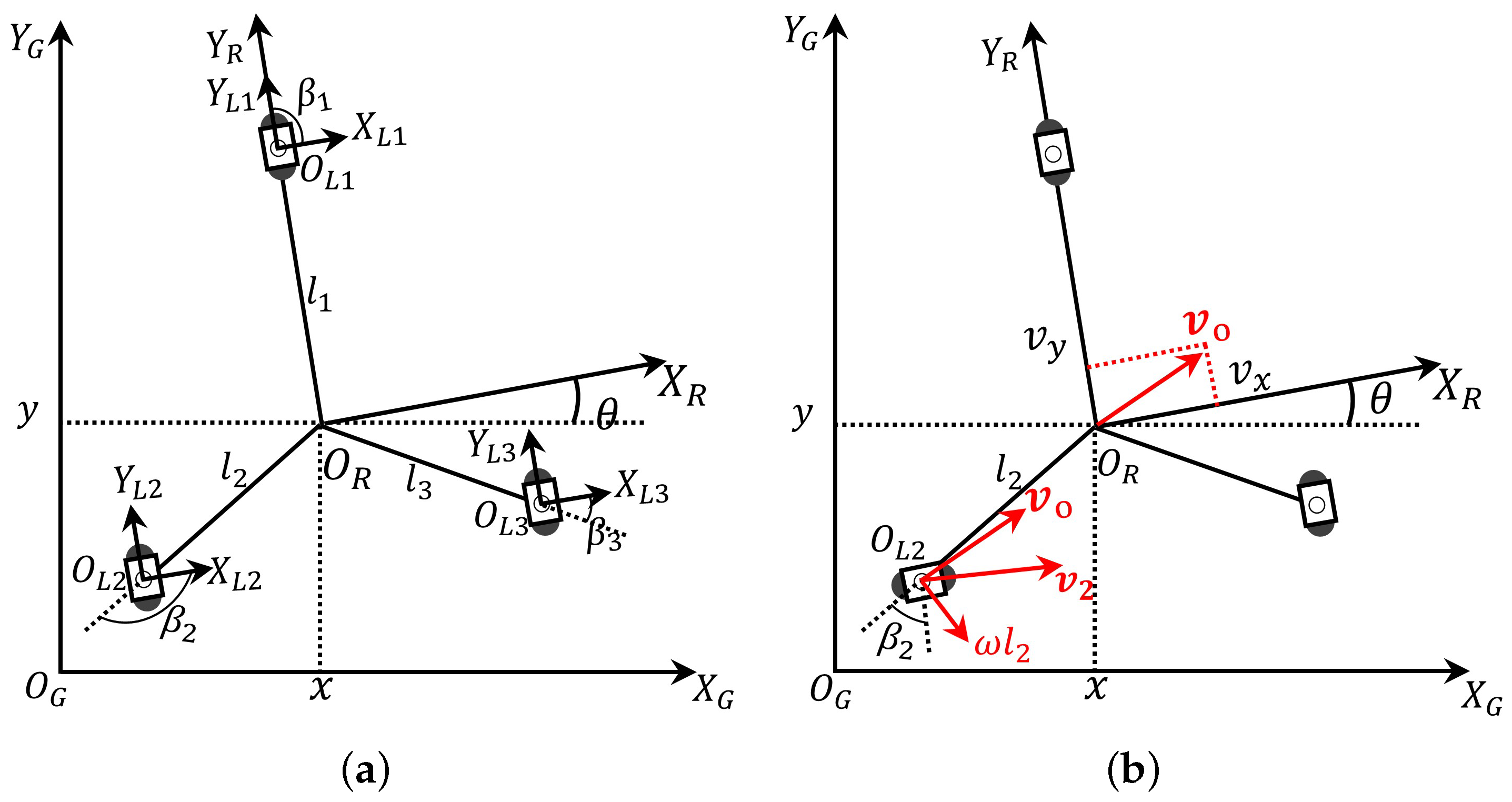
3. Kinematics Analysis
4. Tracking Controller Design
4.1. Design of Control Law
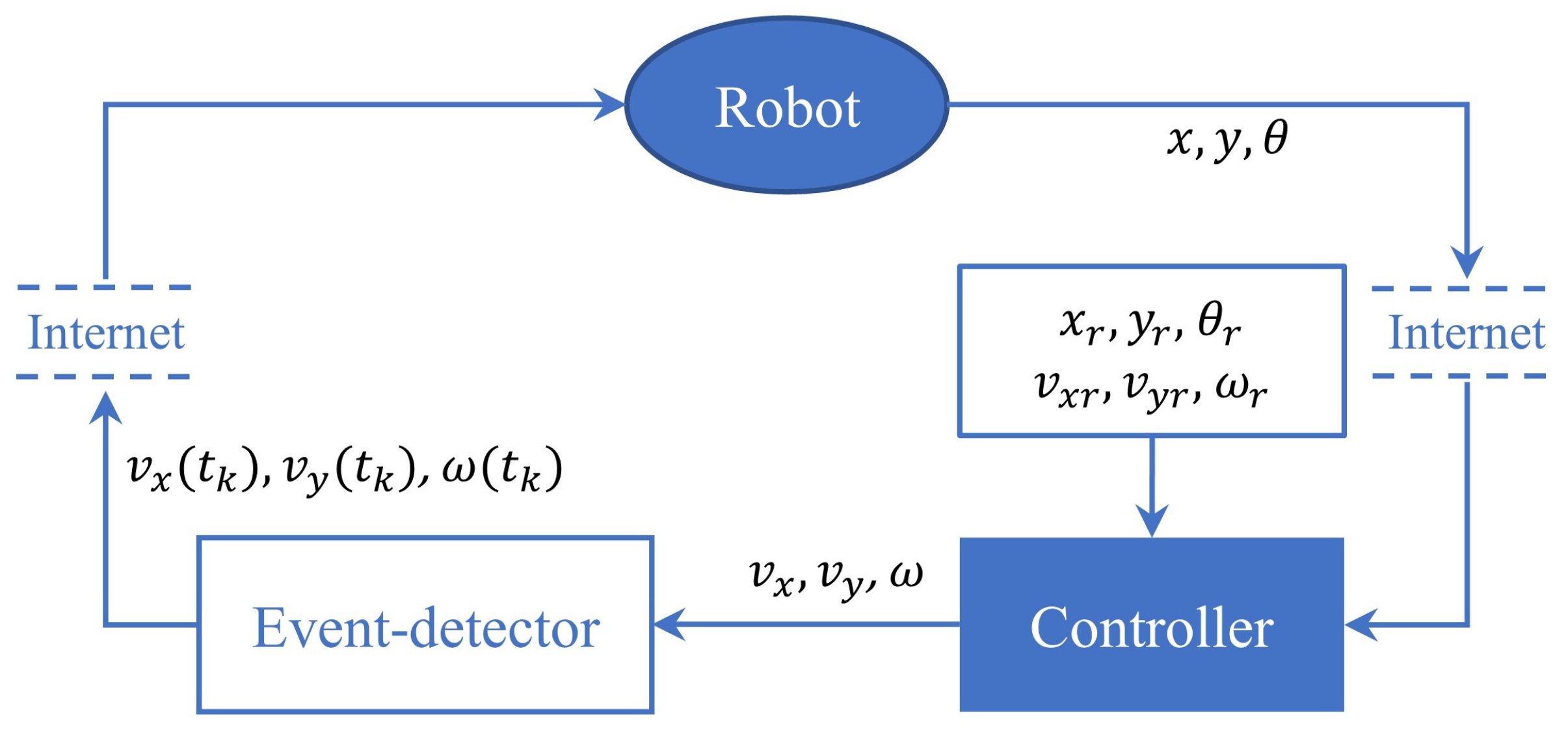
4.2. Trajectory Tracking Control Based on ETM
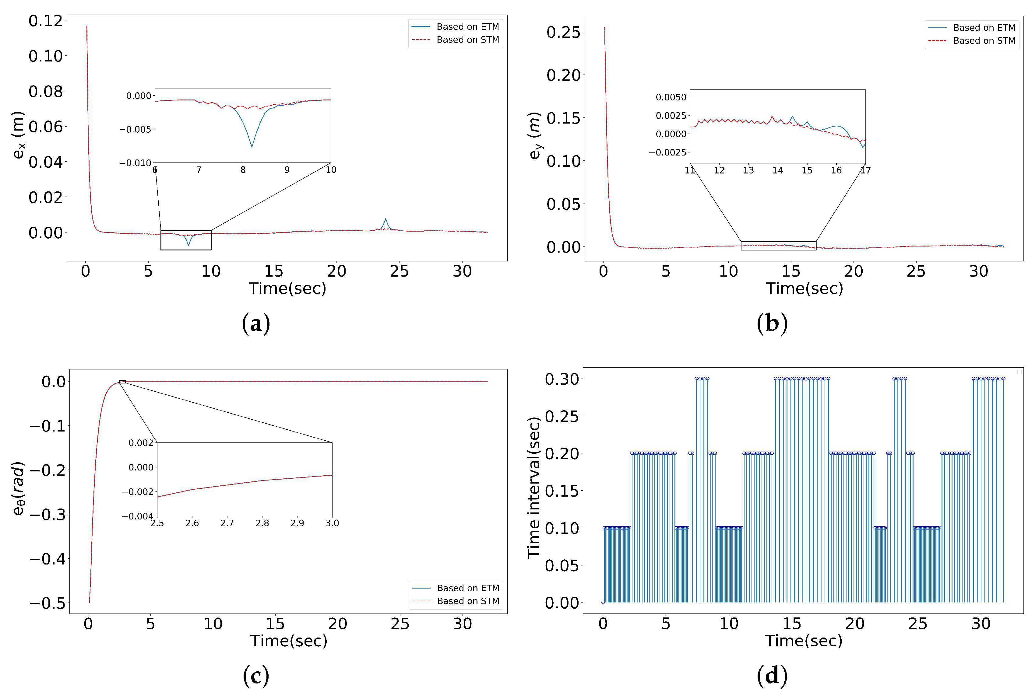
5. Simulation
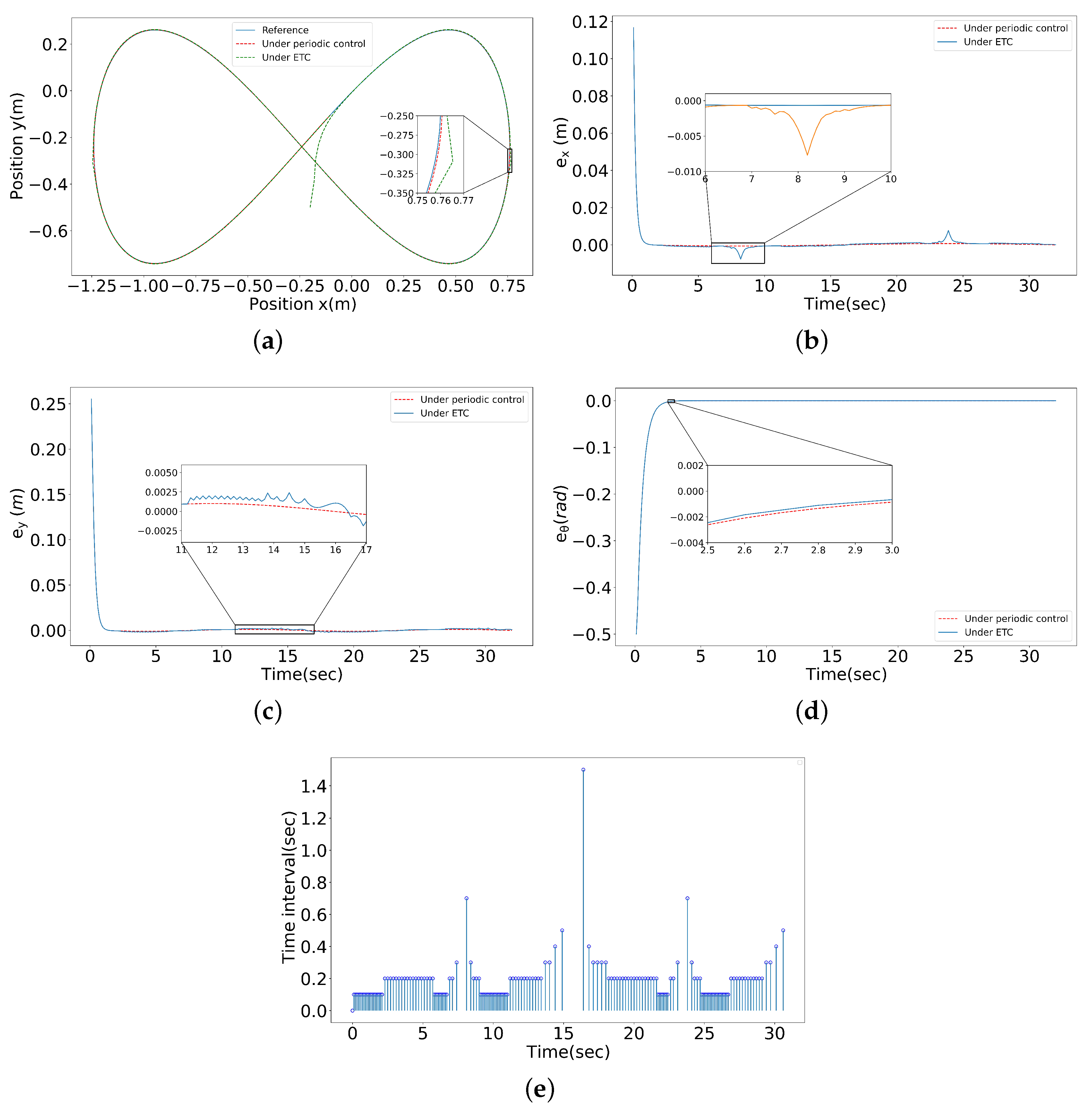
Simulation Results
6. Conclusions
Author Contributions
Funding
Institutional Review Board Statement
Informed Consent Statement
Data Availability Statement
Conflicts of Interest
Abbreviations
| ETC | Event-triggered control |
| ETM | Event-triggered mechanism |
| STM | Self-triggering mechanism |
References
- Yang, G.; Wang, S.Y.; Yang, J.Y. Hybrid knowledge base for care robots. Int. J. Innov. Comp. Inf. Control 2021, 17, 335–343. [Google Scholar]
- Kassaeiyan, P.; Alipour, K.; Tarvirdizadeh, B. A full-state trajectory tracking controller for tractor-trailer wheeled mobile robots. Mech. Mach. Theory 2020, 150, 103872. [Google Scholar] [CrossRef]
- Hamaguchi, M. Damping and transfer control system with parallel linkage mechanism-based active vibration reducer for Omnidirectional Wheeled Robots. IEEE/ASME Trans. Mechatron. 2018, 23, 2424–2435. [Google Scholar] [CrossRef]
- Watson, M.T.; Gladwin, D.T.; Prescott, T.J. Dual-mode model predictive control of an omnidirectional wheeled inverted pendulum. IEEE/ASME Trans. Mechatron. 2019, 24, 2964–2975. [Google Scholar] [CrossRef]
- Watson, M.T.; Gladwin, D.T.; Prescott, T.J. Collinear mecanum drive: Modeling, analysis, partial feedback linearization, and nonlinear control. IEEE/ASME Trans. Robot. 2021, 37, 642–658. [Google Scholar] [CrossRef]
- Long, S.; Terakawa, T.; Komori, M. Effect of double-row active omni wheel on stability of single-track vehicle in roll direction. Mech. Mach. Theory 2021, 163, 104374. [Google Scholar] [CrossRef]
- Yu, S.; Ye, C.; Liu, H. Development of an omnidirectional automated guided vehicle with MY3 wheels. Perspect. Sci. 2016, 7, 364–368. [Google Scholar] [CrossRef]
- Lee, S.M.; Son, H. Improvement of design and motion control for motion platform based on spherical wheels. IEEE/ASME Trans. Mechatron. 2019, 24, 2427–2433. [Google Scholar] [CrossRef]
- Taheri, H.; Zhao, C.X. Omnidirectional mobile robots, mechanisms and navigation approaches. Mech. Mach. Theory 2020, 153, 103958. [Google Scholar] [CrossRef]
- Yang, L.; Liu, Z.M.; Chen, Q.Y. Decoupling active caster omnidirectional mobile robot tracking control considering slip interferences. China Mech. Eng. 2020, 31, 2247–2253. [Google Scholar]
- Terakawa, T.; Komori, M.; Matsuda, K. A novel omnidirectional mobile robot with wheels connected by passive sliding joints. IEEE/ASME Trans. Mechatron. 2018, 23, 1716–1727. [Google Scholar] [CrossRef]
- Fu, J.; Tian, F.; Chai, T. Motion Tracking Control Design for a Class of Nonholonomic Mobile Robot Systems. IEEE Trans. Syst. Man Cybern. Syst. 2020, 50, 2150–2156. [Google Scholar] [CrossRef]
- Li, L.; Liu, Y.H.; Jiang, T. Adaptive trajectory tracking of nonholonomic mobile robots using vision-based position and velocity estimation. IEEE Trans. Cybern. 2018, 48, 571–582. [Google Scholar] [CrossRef]
- Yu, Y.; Liu, X. Model-free fractional-order sliding mode control of electric drive system based on nonlinear disturbance observer. Fractal Fract. 2022, 6, 603. [Google Scholar] [CrossRef]
- Chen, Z.; Liu, Y.; He, W. Adaptive-neural-network-based trajectory tracking control for a nonholonomic wheeled mobile robot with velocity constraints. IEEE Trans. Ind. Electron. 2021, 68, 5057–5067. [Google Scholar] [CrossRef]
- Ding, L.; Han, Q.L.; Ge, X. An overview of recent advances in event-triggered consensus of multiagent systems. IEEE Trans. Cybern. 2018, 48, 1110–1123. [Google Scholar] [CrossRef]
- Liu, X.; Su, X.; Shi, P. Event-triggered sliding mode control of nonlinear dynamic systems. Automatica 2020, 112, 108738. [Google Scholar] [CrossRef]
- Sun, X.L.; Song, X.N. Dissipative analysis and event-triggered exponential synchronization for fractional-Order complex-valued reaction-diffusion neural networks. Int. J. Innov. Comp. Inf. Control 2022, 18, 1519–1536. [Google Scholar]
- Wang, Y.; Zhang, J.; Wu, H. Distributed adaptive mittag–Leffler formation control for second-order fractional multi-agent systems via event-triggered control strategy. Fractal Fract. 2022, 6, 380. [Google Scholar] [CrossRef]
- Demirel, B.; Ghadimi, E.; Quevedo, D.E. Optimal control of linear systems with limited control actions: Threshold-based event-triggered control. IEEE Trans. Control. Netw. Syst. 2018, 5, 1275–1286. [Google Scholar] [CrossRef]
- Qian, Y.Y.; Liu, L.; Feng, G. Event-triggered robust output regulation of uncertain linear systems with unknown exosystems. IEEE Trans. Syst. Man Cybern. Syst. 2021, 51, 4139–4148. [Google Scholar] [CrossRef]
- Huang, J.; Wang, W.; Wen, C. Adaptive event-triggered control of nonlinear systems with controller and parameter estimator triggering. IEEE Trans. Autom. Control 2020, 65, 318–324. [Google Scholar] [CrossRef]
- Su, X.; Wen, Y.; Shi, P. Event-triggered fuzzy control for nonlinear systems via sliding mode approach. IEEE Trans. Fuzzy Syst. 2021, 29, 336–344. [Google Scholar] [CrossRef]
- Dohmann, P.B.g.; Hirche, S. Distributed control for cooperative manipulation with event-triggered communication. IEEE Trans. Robot. 2020, 36, 1038–1052. [Google Scholar] [CrossRef]
- Yao, D.; Li, H.; Lu, R. Distributed sliding-mode tracking control of second-order nonlinear multiagent systems: An event-triggered approach. IEEE Trans. Cybern. 2020, 50, 3892–3902. [Google Scholar] [CrossRef]
- Li, X.; Sun, Z.; Tang, Y. Adaptive event-triggered consensus of multiagent systems on directed graphs. IEEE Trans. Autom. Control 2021, 66, 1670–1685. [Google Scholar] [CrossRef]
- Yuan, J.; Chen, T. Switched fractional order multiagent systems containment control with event-triggered mechanism and input quantization. Fractal Fract. 2022, 6, 77. [Google Scholar] [CrossRef]
- Ni, J.; Shi, P.; Zhao, Y. Fixed-time event-triggered output consensus tracking of high-order multiagent systems under directed interaction graphs. IEEE Trans. Cybern. 2022, 52, 6391–6405. [Google Scholar] [CrossRef]
- Campion, G.; Bastin, G.; Dandrea-Novel, B. Structural properties and classification of kinematic and dynamic models of wheeled mobile robots. IEEE Trans. Robot. Autom. 1996, 12, 47–62. [Google Scholar] [CrossRef]
- Jiangdagger, Z.P.; Nijmeijer, H. Tracking control of mobile robots: A case study in backstepping. Automatica 1997, 33, 1393–1399. [Google Scholar] [CrossRef]
- Wan, S.J.; Zhang, Y.Y.; He, Z.Y.; Chen, L. Periodic event-triggered tracking control for nonholonomic wheeled mobile robots. Int. J. Innov. Comp. Inf. Control 2022, 18, 1507–1517. [Google Scholar]


Disclaimer/Publisher’s Note: The statements, opinions and data contained in all publications are solely those of the individual author(s) and contributor(s) and not of MDPI and/or the editor(s). MDPI and/or the editor(s) disclaim responsibility for any injury to people or property resulting from any ideas, methods, instructions or products referred to in the content. |
© 2023 by the authors. Licensee MDPI, Basel, Switzerland. This article is an open access article distributed under the terms and conditions of the Creative Commons Attribution (CC BY) license (https://creativecommons.org/licenses/by/4.0/).
Share and Cite
Ao, W.; Zhang, L.; Zhang, H.; Li, Z.; Huang, G. Structure Design and Event-Triggered Control of a Modular Omnidirectional Mobile Chassis of Life Support Robotics. Fractal Fract. 2023, 7, 121. https://doi.org/10.3390/fractalfract7020121
Ao W, Zhang L, Zhang H, Li Z, Huang G. Structure Design and Event-Triggered Control of a Modular Omnidirectional Mobile Chassis of Life Support Robotics. Fractal and Fractional. 2023; 7(2):121. https://doi.org/10.3390/fractalfract7020121
Chicago/Turabian StyleAo, Wengang, Longfa Zhang, Huiyan Zhang, Zufeng Li, and Gouyang Huang. 2023. "Structure Design and Event-Triggered Control of a Modular Omnidirectional Mobile Chassis of Life Support Robotics" Fractal and Fractional 7, no. 2: 121. https://doi.org/10.3390/fractalfract7020121
APA StyleAo, W., Zhang, L., Zhang, H., Li, Z., & Huang, G. (2023). Structure Design and Event-Triggered Control of a Modular Omnidirectional Mobile Chassis of Life Support Robotics. Fractal and Fractional, 7(2), 121. https://doi.org/10.3390/fractalfract7020121