Abstract
This paper addresses the problems of structure design and trajectory tracking control of a mobile chassis of life support robots. First, a novel omnidirectional mobile chassis structure is proposed, which consists of three pairs of modular wheel sets with independent drive and steering capability. This allows robots to possess omnidirectional mobility and structural reliability. Then, the trajectory tracking control law is established by combining kinematics analysis and Lyapunov theory. Furthermore, considering the requirement of life support robots to be used under network control, this paper proposes an event-triggered trajectory tracking control scheme to improve the utilization efficiency of communication resources. Finally, the effectiveness of the omnidirectional mobile chassis and the event-triggered control law designed in this paper are demonstrated by numerical simulation results.
1. Introduction
In order to solve the problem of increased elderly care brought about by an ageing population, one of the most effective ways is to develop life support robotics with functions of life assistance, daily nursing, emotional care, etc. Thus, an outstanding mobile performance is the key function of life support robotics to realize this purpose [1]. However, the placement of indoor items on the ground and the living habits of people will lead to an irregular operation area of the robot. This typical unstructured environment requires a robotic chassis with enough flexible mobility, a simple and reliable structure, low movement noise and the ability to not get easily tangled in ground debris. Moreover, the motion control should be safe, precise and stable. For the motion requirements of life support robotics, how to design a reliable omnidirectional mobile chassis and derive the efficient trajectory tracking control law are the main research contents of this paper.
Most of the existing typical indoor mobile robots are differential wheeled robots (Figure 1a), which use two parallel ordinary wheels as driving wheels, and the turning radius, generated by the difference in their speeds, is used to realize the steering of robots [2]. They are widely used for their simple and reliable structure. However, robots with differential drive are a kind of nonholonomic robot; that is, the change in the motion direction of the robot requires a certain turning radius, which will consume extra time and space and reduce the overall flexibility. In contrast, holonomic robots can move immediately in an arbitrary direction without a turning radius. Typical holonomic robots adopt the structure of a Mecanum wheel (Figure 1b) or an omni wheel (Figure 1c). These robots can be used in work scenarios that require high motion performance and have a narrow working space [3,4,5]. However, the ground contact point is discontinuous, and because of that, their circumferences consist of free rollers rather than a complete circle, which will lead to unavoidable vertical vibration and a low load capacity [6].
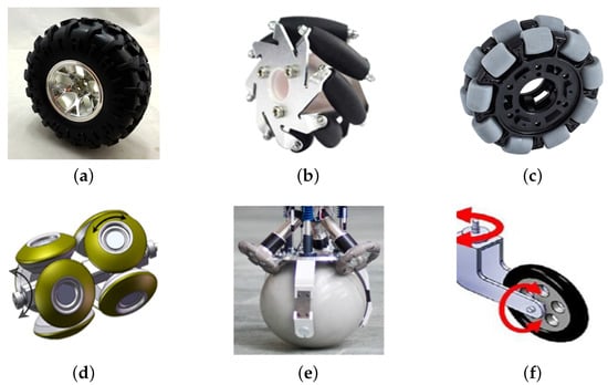
Figure 1.
Varieties of wheel constructions. (a) Differential wheel. (b) Mecanum wheel. (c) Orthogonal wheel. (e) Spherical wheel. (f) Caster wheel.
As an alternative, the structure of orthogonal wheels (Figure 1d), which have two spherical-segment wheels, can ensure continuous contact with the ground and realize omnidirectional driving at the same time [7]. However, the gap between the spherical crowns is large, and the rotation axis is easy to be interfered with by debris. In addition, the spherical wheel (Figure 1e) can also realize omnidirectional movement, but robots with a single spherical wheel structure are statically unbalanced robots [8], which decreases the control of the robot. In addition, the multi-ball wheel structure is extremely complex [9], leading to a low reliability and a low practical value. The caster wheel (Figure 1f) has been proposed to solve the structural problems caused by the above unique wheels [10]. A caster wheel can achieve the steering of the driving wheel itself by adding an offset rotary joint above the rotation axis of the ordinary driving wheel. However, omnidirectional mobile robots using caster wheels may have shock and motion uncertainty, since the motion direction changes too fast [11].
As none of the above wheels can meet the movement requirements of life support robotics in an indoor unstructured environment, to solve this problem, a novel omnidirectional mobile chassis structure is proposed in this paper. The omnidirectional mobile chassis is mainly composed of three modular wheel sets, mounting plates, a control unit, etc. Based on the non-offset caster wheel and a modular design, each wheel set can drive and steer independently, which eliminates the vibration caused by Mecanum wheels or omni wheels, and the structure is more compact than that of orthogonal wheels. Moreover, compared with ordinary caster wheels, the stability during the process of sharp steering is guaranteed because the motion pattern can be smoothly changed by the non-offset design. Meanwhile, the steering of each driving wheel is realized by a worm gear drive. The self-locking property of its drive can prevent the movement direction from being deviated by lateral force as it works, and the modular design is convenient for subsequent disassembly and debugging.
Trajectory tracking is the core of robot motion control. The achievement of efficient trajectory tracking can directly determine the degree of robot intelligence. The main control methods of robot trajectory tracking include the backstepping technique [12], adaptive control [13], sliding mode control [14], neural network control [15], etc. The goal of trajectory tracking control is to derive a suitable control law so that the error between the reference path and the current pose of robots converges to the origin asymptotically.
In general, the trajectory tracking control approaches realizes the motion control of the robot by updating the control law periodically, which takes a small sampled interval to guarantee a high-class tracking performance. Nevertheless, for network control systems, frequent updating of the control law may increase energy consumption and waste the limited communication resources.
To solve this problem, event-triggered control (ETC) methods have been broadly developed in [16,17,18,19,20,21,22,23,24,25,26,27,28]. The core idea of ETC is that only when a certain index of the system meets the preset conditions can data be transmitted, which ensures that the system can simultaneously meet the desired performance and reduce the occupation of computing and communication resources [16,17,18,19]. For linear systems, Ref [20] introduced an event-triggered mechanism (ETM) to save the communication between the controller and the actuator for optimal control of linear systems. An event-triggered strategy was proposed to address the robust output regulation problem for linear systems in [21]. For nonlinear systems, to make better use of the communication resources, the controller and parameter estimator were both under an ETM in [22]. In [23], based on an ETM, the problem of continuous-time dynamic sliding mode control for T-S fuzzy nonlinear systems was solved. As for multiagent systems, Ref. [24] proposed an ETC strategy for cooperative manipulation tasks. The system nonlinearities were solved by an event-triggered sliding mode tracking protocol in [25]. The common problem of linear multiagent systems on directed graphs was addressed by adaptive event-triggered protocols in [26]. Ref [27] combined ETM and input quantization to reduce the action frequency of a controller. In order to alleviate the burden of network communication, Ref [28] presented an event-triggered fixed-time distributed observer and a fixed-time controller. Although some works have been reported on the theoretical and practical aspects of ETC, little research exists focusing on solving the trajectory tracking control problem of wheeled mobile robots under an ETM.
Aiming at the application of life support robotics in different scenarios, and combining Lyapunov theory with ETM, this paper proposes a periodic trajectory tracking control method applied to the independent operation of life support robots and an event-triggered trajectory tracking control method under network control in order to meet different control performance requirements.
2. Novel Omnidirectional Mobile Chassis
The research of this paper is based on a modular three-wheeled omnidirectional mobile chassis of a life support robot. The chassis, which has been independently developed and designed by our team, can move flexibly in an indoor unstructured environment and achieve zero radius steering in a narrow space. This section analyzes the principles of omnidirectional chassis movement and proposes the mechanical structure of the novel omnidirectional chassis based on these principle.
2.1. Principle Analysis of Omnidirectional Movement
In this part, the motion constraint conditions of common wheeled robots are analyzed, and the motion principle of the omnidirectional mobile chassis designed in this paper is presented.
In order to discuss omnidirectional movement conditions, the global reference frame , the robot reference frame and the wheel reference frame of a common wheeled mobile robot are shown in Figure 2a. The pose of the robot in the global reference frame is represented by the vector , the velocity of the robot reference frame is represented by the vector and the conversion formula between the two is represented as follows:
where is the angle between and and is the rotation matrix that transforms the vector in the global reference frame to the vector in the robot reference frame, where
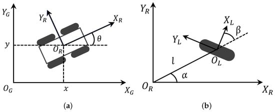
Figure 2.
A wheeled mobile robot reference frame. (a) The pose of the robot in the global reference frame. (b) The pose of the wheel in the robot reference frame.
The position of the wheel is shown in Figure 2b. The distance from the center of the wheel, , to the origin, , is l, and the , called the mounting line, is at an angle from . The axis of the wheel is at an angle of from the mounting line. Thus, by projecting the velocity of the robot reference frame in the wheel forward direction and the wheel axis direction, respectively [10], the constraints of one wheel are as follows:
- Along the wheel forward direction:
- Along the wheel axis direction:
As shown above, when the wheel is a differential wheel, substituting into (4) means that (4) is a nonholonomic constraint, and a robot with nonholonomic constraint cannot realize omnidirectional movement. For the rest of the wheels, in contrast, and in (3) and (4) have fixed expressions separately, which means that and can take any value within a certain range, i.e., the robot is under holonomic constraints and can use multiple wheels to realize omnidirectional movement. In particular, when the wheel is a caster wheel and , (4) also becomes a nonholonomic constraint. Unlike the differential wheel, in this case, is not a constant but a variable. Therefore, a robot with non-offset caster wheels can still move in any direction in the plane without a turning radius by changing the value of .
Thus, based on the motion principle of a non-offset caster wheel, an innovative omnidirectional mobile chassis suitable for life support robots in an indoor unstructured environment is designed in this paper.
2.2. Structure of Omnidirectional Mobile Chassis
Here, based on the above analysis of the omnidirectional movement principle, a novel modular three-wheeled omnidirectional mobile chassis is proposed in this subsection. As shown in Figure 3a, the omnidirectional mobile chassis was mainly composed of three modular wheel sets and mounting plates. The three pairs of wheel sets were fixed on the mounting plate at an angle of to each other. Each pair of wheel sets was mainly composed of a steering motor, a hub motor, a transmission assembly, mounting plates, etc., which could drive and steer independently (Figure 3b).
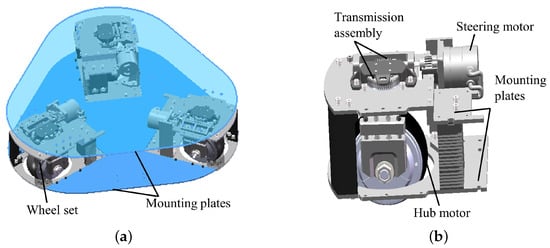
Figure 3.
Construction of a modular omnidirectional mobile chassis. (a) Overall structure. (b) Mechanism of a single wheel set.
On the one hand, because the steering of the hub motor is realized by a worm gear drive, the self-locking of its drive means that the value of is unaffected by external force, which ensures the speed stability of the chassis when static or moving. On the other hand, when the chassis is at rest, the wheel plane of each driving wheel has a common intersection line, which means that the chassis will not be influenced by the rolling friction due to external force in the parking state, and has static self-locking ability to a certain extent.
Then, in order to discuss the motion ability of the chassis proposed in this paper, the motion modes of the chassis are divided into four types according to the motion requirements of the robot including parking, turning in situ, straight driving (no steering) and meandering path driving. Certainly, different motion modes have different hub motor layouts. For the parking model, the wheel plane of each driving wheel has a common intersection line (Figure 4a), i.e., . For the turning in situ model (Figure 4b), the wheel plane of each driving wheel is perpendicular to the mounting line, corresponding to . As shown in Figure 4c, when the chassis is driving in a straight line, the direction of each hub motor is consistent with the movement direction of the chassis. As opposed to driving straight, when the chassis is moving in a meandering path, is not fixed but varies with time (Figure 4d).
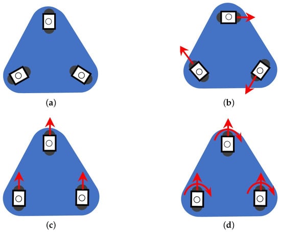
Figure 4.
Motion models of the omnidirectional chassis. (a) Parking. (b) Turning in situ. (c) Driving in a straight line (no steering). (d) Meandering path driving.
3. Kinematics Analysis
In order to derive the kinematics formulas, the reference frame of the proposed chassis is established in Figure 5a. A wheel set with a mounting line collinear with of the reference frame is assigned as wheel set 1, and the others as wheel sets 2 and 3 counter-clockwise.
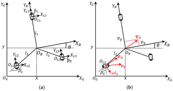
Figure 5.
Kinematics reference frame. (a) Three-wheeled omnidirectional mobile chassis reference frame. (b) The velocity of wheel set 2.
First, based on the vector v obtained by (1), let , then the velocity of the wheel set i can be expressed as
where is the velocity of wheel set i, is the velocity of the centroid of the chassis, is the angular velocity with which the chassis rotates around the centroid and is the radius vector. That is, the speed of each hub motor is and the orientation is consistent with . Take wheel set 2 as an example, shown in Figure 5b. Then, combining the geometric characteristics of the chassis and the conditions (3) and (4), the constraint conditions of wheel set i can be represented as follows:
Next, the following equation is obtained from (6) and (7).
Therefore, the forward kinematics of the omnidirectional chassis proposed is represented by
Here, , , and are constants and . is variable, with initial values , and .
4. Tracking Controller Design
4.1. Design of Control Law
In this section, the objective is to design the control law, so that the tracking error converges to the origin asymptotically. The tracking error system of the robot reference frame is first established. The velocity in (1) is used as the virtual input variable of the system, and the actual input variable is . The conversion of these two variables is realized by (5).
In the global reference frame, the actual pose of the robot is defined as and the reference pose is . Taking as the tracking error in the robot reference frame, the error equations of trajectory tracking in the robot reference frame are established as follows:
From (1), we can obtain that
where is the reference velocity of the robot in the robot reference frame. Then, by differentiating (10) and substituting (11) and (12), the tracking error dynamics can be represented by the following equation:
Inspired by [30], the trajectory tracking control law can be derived as:
where , and are positive constants.
Based on the Lyapunov stability theory, the asymptotic stability condition for the tracking error dynamics in (13) is proposed in Theorem 1.
Theorem 1.
Proof of Theorem 1.
The Lyapunov function can be selected as:
The derivative of (16) is given by
According to (16) and (18), it can be easily confirmed that and . Based on this, V is the lower bound because and the upper bound of V is determined by . Thus, we can deduce that V is bound. From (16), it is easy to conclude that e is bound. In addition, is certainly bound and is bound since and are positive constants in (14). Moreover, using (13), is also bound.
Then, by differentiating (18), we obtain
That is bound is guaranteed since e and are bound. Therefore, is uniformly continuous. According to Barbalat’s lemma in [13], we obtain
The validity of (20) implies
Thus, the tracking error e is asymptotically stable. The proof is complete. □
Remark 1.
The means of deriving control law (14) is a Lyapunov direct method [30]; that is, by appropriately choosing the Lyapunov candidate function to make the derivative of the corresponding candidate function along the system solution be negative definite or semi-negative definite, so that a stable control law can be given. On the one hand, the tracking performance can be guaranteed by the control law from the direct Lyapunov method. On the other hand, the control law can make the derivative of Lyapunov function for tracking error systems become orderly as well, which may simplify the design of subsequent ETM.
4.2. Trajectory Tracking Control Based on ETM
When a life support robot works in a hospital, nursing home or other large-scale environments, in order to satisfy the requirements for long-term continuous work and the reasonable utilization of system resources, the upper-level control system of the robot will be shut down. Meanwhile, only the embedded system and the sensor work normally, so the object will be controlled via a remote network control method. At this time, the traditional period control will cause high-frequency updating of the control law, which will not only occupy a lot of computing and communication resources, but also accelerate the ageing of the actuator. In fact, when the system becomes stable, the certainty index can be maintained even without updating the control law [20]. Therefore, to save the limited communication resources in the case of network control, an event-triggered strategy for trajectory tracking control is proposed in this section.
In ETC (Figure 6), the control law is updated only at discrete time instants and , where is the initial sampling instant and is event-triggering instant satisfying . Suppose is already known and the task is to design suitable triggering conditions to determine [22]. To this end, in the time period , the control inputs are , and , respectively. As a result, the tracking error system (13) becomes
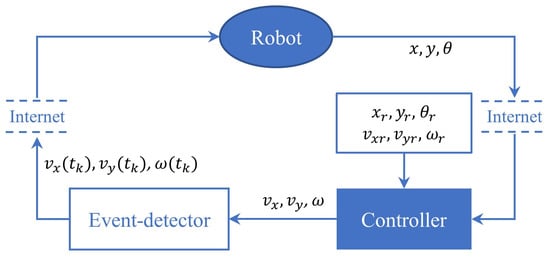
Figure 6.
ETC frame of the life support robotic.
Next, the control variables are defined as , and , and by substituting them into (22), we obtain
For system (23), the following ETM can be designed:
where and are constants that satisfy and .
We now analyze the designed ETM and establish the stability of the tracking error system (23). The result is stated in the following theorem.
Theorem 2.
Proof of Theorem 2.
From (25), satisfies
Therefore, the asymptotic stability of the system (24) is guaranteed. This completes the proof. □
Remark 2.
Since the local high-frequency sampling and Zeno behavior can be avoided with maximum function [31], the ETM (24) is modified as follows:
where and are constants that satisfy and .
5. Simulation
In order to verify the motion performance of the omnidirectional mobile chassis and the availability of the trajectory tracking control method proposed in this paper, a numerical simulation experiment was carried out first. The reference trajectory equation is as follows:
The parameters were set as follows: the initial pose of the robot was set as . Secondly, due to the demand of safety for the life support robot, the maximum speed of each hub motor was limited to and its steering speed was . Then, and determine the weight of the , and in calculating the control inputs, respectively, so they were chosen as , and . In ETC, and should be selected for a tradeoff between trajectory performance and event-triggered frequency, and they were chosen through trial and error as , , and .
Simulation Results
The numerical simulation experiment was carried out based on the above settings, and the results are shown in Figure 7.
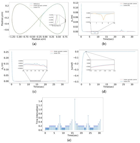
Figure 7.
Simulation results by different control methods. (a) Trajectory tracking status. (b) Pose error, . (c) Pose error, . (d) Pose error, . (e) Triggering frequency.
As can be seen from the simulation results, the periodic control method could ensure an accurate tracking path (Figure 7a), the tracking error could converge to zero rapidly and the error curve was stable (Figure 7b–d). When the network control was adopted, the robot could approximately catch up with the reference trajectory after the ETM was introduced (Figure 7a) and the tracking error curve eventually approached near zero (Figure 7b–d).
However, it can be seen from Figure 7b that the curve about under ETC has obvious local oscillations and sharp peaks, which deviate from the origin locally. On the one hand, the time intervals of local deviations correspond to large triggering intervals in Figure 7e, indicating that the triggering frequencies in these periods are low. On the other hand, from the ETM (27), it can be seen that the control law will be updated only when both and meet the trigger conditions. However, when the curve of has a peak period, the corresponding curve of in Figure 7c fluctuates only a little, so the position error cannot be corrected in time during this period.
To further improve the tracking efficiency, by combining the characteristics of periodic control, a self-triggering mechanism (STM) was developed under the premise of (27), which specifies the maximum event-triggering interval. Numerical simulation results are shown in Figure 8.
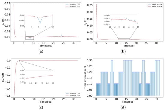
Figure 8.
Simulation results with STM. (a) Pose error, . (b) Pose error, . (c) Pose error, . (d) Triggering frequency.
It is observed that under the action of the STM, the convergence state of and can be significantly improved compared with the ETM in Figure 8a,b. The curve of is almost coincident with its counterpart in ETC in Figure 8c. In addition, the STM can also reduce the trigger frequency of the system, as shown in Figure 8d. These results show that compared with the ETM proposed above, the STM can further improve the trajectory tracking accuracy while guaranteeing a similar trigger frequency.
To sum up, compared to the periodic control method, the ETC leads to approximate trajectory tracking rather than accurate trajectory tracking. However, the ETC significantly lowers the updating frequency of the control law, which can observably reduce the burden of the system communication. Moreover, the error of the pose converges quickly, regardless of whether it is controlled by the period time-based control or the ETC, which also verifies the flexibility of the chassis structure proposed in this paper, since it can rapidly change the direction of motion.
6. Conclusions
This paper has investigated the structure design and trajectory tracking control of a chassis for life support robots. Firstly, considering the characteristics of life support robots working in an indoor unstructured environment, this paper designed a modular three-wheeled omnidirectional mobile chassis, which has the merits of flexible movement, low movement noise, strong bearing capacity, long working life and so on. Then, the kinematics of the omnidirectional mobile chassis were analyzed, and the trajectory tracking control method based on the time-triggered mechanism and ETM were proposed for different working scenarios of the life support robot. Finally, the advantages of the proposed chassis structure and the effectiveness of the trajectory tracking method were verified by simulation experiments. The universality of the trajectory tracking control method for life support robots in realistic complex paths will be part of our future work.
Author Contributions
Conceptualization, W.A. and L.Z.; methodology, H.Z.; software, Z.L.; validation, W.A., L.Z. and H.Z.; formal analysis, Z.L. and G.H; investigation, W.A.; resources, W.A.; data curation, G.H.; writing—original draft preparation, L.Z.; writing—review and editing, L.Z. and H.Z.; visualization, G.H.; supervision, H.Z.; project administration, Z.L.; funding acquisition, W.A. All authors have read and agreed to the published version of the manuscript.
Funding
This research was funded by the National Key R&D Program of China under grant no. 2022YFE0107300, in part by the National Natural Science Foundation of China under grant 62003062, in part by the Chongqing Technology Innovation and Application Development Project under grant no. CSTB2022TIAD-KPX0162, in part by the Chongqing Natural Science Foundation under grant no. cstc2020jcyj-msxmX0067 and in part by the Scientific and Technological Research Program of Chongqing Municipal Education Commission under grant no. KJQN202000821.
Institutional Review Board Statement
Not applicable.
Informed Consent Statement
Not applicable.
Data Availability Statement
Not applicable.
Conflicts of Interest
The authors declare no conflict of interest.
Abbreviations
The following abbreviations are used in this manuscript:
| ETC | Event-triggered control |
| ETM | Event-triggered mechanism |
| STM | Self-triggering mechanism |
References
- Yang, G.; Wang, S.Y.; Yang, J.Y. Hybrid knowledge base for care robots. Int. J. Innov. Comp. Inf. Control 2021, 17, 335–343. [Google Scholar]
- Kassaeiyan, P.; Alipour, K.; Tarvirdizadeh, B. A full-state trajectory tracking controller for tractor-trailer wheeled mobile robots. Mech. Mach. Theory 2020, 150, 103872. [Google Scholar] [CrossRef]
- Hamaguchi, M. Damping and transfer control system with parallel linkage mechanism-based active vibration reducer for Omnidirectional Wheeled Robots. IEEE/ASME Trans. Mechatron. 2018, 23, 2424–2435. [Google Scholar] [CrossRef]
- Watson, M.T.; Gladwin, D.T.; Prescott, T.J. Dual-mode model predictive control of an omnidirectional wheeled inverted pendulum. IEEE/ASME Trans. Mechatron. 2019, 24, 2964–2975. [Google Scholar] [CrossRef]
- Watson, M.T.; Gladwin, D.T.; Prescott, T.J. Collinear mecanum drive: Modeling, analysis, partial feedback linearization, and nonlinear control. IEEE/ASME Trans. Robot. 2021, 37, 642–658. [Google Scholar] [CrossRef]
- Long, S.; Terakawa, T.; Komori, M. Effect of double-row active omni wheel on stability of single-track vehicle in roll direction. Mech. Mach. Theory 2021, 163, 104374. [Google Scholar] [CrossRef]
- Yu, S.; Ye, C.; Liu, H. Development of an omnidirectional automated guided vehicle with MY3 wheels. Perspect. Sci. 2016, 7, 364–368. [Google Scholar] [CrossRef]
- Lee, S.M.; Son, H. Improvement of design and motion control for motion platform based on spherical wheels. IEEE/ASME Trans. Mechatron. 2019, 24, 2427–2433. [Google Scholar] [CrossRef]
- Taheri, H.; Zhao, C.X. Omnidirectional mobile robots, mechanisms and navigation approaches. Mech. Mach. Theory 2020, 153, 103958. [Google Scholar] [CrossRef]
- Yang, L.; Liu, Z.M.; Chen, Q.Y. Decoupling active caster omnidirectional mobile robot tracking control considering slip interferences. China Mech. Eng. 2020, 31, 2247–2253. [Google Scholar]
- Terakawa, T.; Komori, M.; Matsuda, K. A novel omnidirectional mobile robot with wheels connected by passive sliding joints. IEEE/ASME Trans. Mechatron. 2018, 23, 1716–1727. [Google Scholar] [CrossRef]
- Fu, J.; Tian, F.; Chai, T. Motion Tracking Control Design for a Class of Nonholonomic Mobile Robot Systems. IEEE Trans. Syst. Man Cybern. Syst. 2020, 50, 2150–2156. [Google Scholar] [CrossRef]
- Li, L.; Liu, Y.H.; Jiang, T. Adaptive trajectory tracking of nonholonomic mobile robots using vision-based position and velocity estimation. IEEE Trans. Cybern. 2018, 48, 571–582. [Google Scholar] [CrossRef]
- Yu, Y.; Liu, X. Model-free fractional-order sliding mode control of electric drive system based on nonlinear disturbance observer. Fractal Fract. 2022, 6, 603. [Google Scholar] [CrossRef]
- Chen, Z.; Liu, Y.; He, W. Adaptive-neural-network-based trajectory tracking control for a nonholonomic wheeled mobile robot with velocity constraints. IEEE Trans. Ind. Electron. 2021, 68, 5057–5067. [Google Scholar] [CrossRef]
- Ding, L.; Han, Q.L.; Ge, X. An overview of recent advances in event-triggered consensus of multiagent systems. IEEE Trans. Cybern. 2018, 48, 1110–1123. [Google Scholar] [CrossRef]
- Liu, X.; Su, X.; Shi, P. Event-triggered sliding mode control of nonlinear dynamic systems. Automatica 2020, 112, 108738. [Google Scholar] [CrossRef]
- Sun, X.L.; Song, X.N. Dissipative analysis and event-triggered exponential synchronization for fractional-Order complex-valued reaction-diffusion neural networks. Int. J. Innov. Comp. Inf. Control 2022, 18, 1519–1536. [Google Scholar]
- Wang, Y.; Zhang, J.; Wu, H. Distributed adaptive mittag–Leffler formation control for second-order fractional multi-agent systems via event-triggered control strategy. Fractal Fract. 2022, 6, 380. [Google Scholar] [CrossRef]
- Demirel, B.; Ghadimi, E.; Quevedo, D.E. Optimal control of linear systems with limited control actions: Threshold-based event-triggered control. IEEE Trans. Control. Netw. Syst. 2018, 5, 1275–1286. [Google Scholar] [CrossRef]
- Qian, Y.Y.; Liu, L.; Feng, G. Event-triggered robust output regulation of uncertain linear systems with unknown exosystems. IEEE Trans. Syst. Man Cybern. Syst. 2021, 51, 4139–4148. [Google Scholar] [CrossRef]
- Huang, J.; Wang, W.; Wen, C. Adaptive event-triggered control of nonlinear systems with controller and parameter estimator triggering. IEEE Trans. Autom. Control 2020, 65, 318–324. [Google Scholar] [CrossRef]
- Su, X.; Wen, Y.; Shi, P. Event-triggered fuzzy control for nonlinear systems via sliding mode approach. IEEE Trans. Fuzzy Syst. 2021, 29, 336–344. [Google Scholar] [CrossRef]
- Dohmann, P.B.g.; Hirche, S. Distributed control for cooperative manipulation with event-triggered communication. IEEE Trans. Robot. 2020, 36, 1038–1052. [Google Scholar] [CrossRef]
- Yao, D.; Li, H.; Lu, R. Distributed sliding-mode tracking control of second-order nonlinear multiagent systems: An event-triggered approach. IEEE Trans. Cybern. 2020, 50, 3892–3902. [Google Scholar] [CrossRef]
- Li, X.; Sun, Z.; Tang, Y. Adaptive event-triggered consensus of multiagent systems on directed graphs. IEEE Trans. Autom. Control 2021, 66, 1670–1685. [Google Scholar] [CrossRef]
- Yuan, J.; Chen, T. Switched fractional order multiagent systems containment control with event-triggered mechanism and input quantization. Fractal Fract. 2022, 6, 77. [Google Scholar] [CrossRef]
- Ni, J.; Shi, P.; Zhao, Y. Fixed-time event-triggered output consensus tracking of high-order multiagent systems under directed interaction graphs. IEEE Trans. Cybern. 2022, 52, 6391–6405. [Google Scholar] [CrossRef]
- Campion, G.; Bastin, G.; Dandrea-Novel, B. Structural properties and classification of kinematic and dynamic models of wheeled mobile robots. IEEE Trans. Robot. Autom. 1996, 12, 47–62. [Google Scholar] [CrossRef]
- Jiangdagger, Z.P.; Nijmeijer, H. Tracking control of mobile robots: A case study in backstepping. Automatica 1997, 33, 1393–1399. [Google Scholar] [CrossRef]
- Wan, S.J.; Zhang, Y.Y.; He, Z.Y.; Chen, L. Periodic event-triggered tracking control for nonholonomic wheeled mobile robots. Int. J. Innov. Comp. Inf. Control 2022, 18, 1507–1517. [Google Scholar]
Disclaimer/Publisher’s Note: The statements, opinions and data contained in all publications are solely those of the individual author(s) and contributor(s) and not of MDPI and/or the editor(s). MDPI and/or the editor(s) disclaim responsibility for any injury to people or property resulting from any ideas, methods, instructions or products referred to in the content. |
© 2023 by the authors. Licensee MDPI, Basel, Switzerland. This article is an open access article distributed under the terms and conditions of the Creative Commons Attribution (CC BY) license (https://creativecommons.org/licenses/by/4.0/).