1. Introduction
The concept of smart infrastructure is derived from the concept of smart city, and a smart city is described as a comprehensive system with different elements such as the people, governance, environment, economy, mobility and the living conditions within a given geographical space that efficiently apply ICT to promote a smart sustainable environment [
1].
Applications of the smart concept in smart infrastructure include the use of real-time information and the integrated evolution of urban form. Additionally, multi-modal transport networks that are cost-effective, efficient, adequate and equitable for movement of the people, goods, and services in a more socially, environmentally, and physically sustainable area over a long period of time are also a key component [
2].
In this context a smart infrastructure is developed through the combination of physical and digital infrastructures, providing more information to make management decisions [
3].
The specification for information management for the capital/delivery phase of construction projects using building information modeling [
4] defines Building Information Modeling (BIM) as “the process of designing, constructing, or operating a building or infrastructure asset using electronic object-orientated information”.
Although infrastructure projects possess intrinsic characteristics that demand different modeling methodologies, the base of BIM application in terms of data management and exchange remains the same [
5].
The European Commission (hereafter EC) has thus supported, promoted, and developed several policies and initiatives aiming to foster the digitalization in the construction sector [
6].
These include inter alia the Strategy for the sustainable competitiveness of the construction sector and its enterprises [
7], the EU BIM Task Group [
8] and the EU Digital Construction platform [
9].
The digitalization of the construction sector is also integrated into other policy areas such as the EU directive on Public Procurement [
10], which promotes the implementation of BIM in public work contracts and design competitions as a basis for requesting the use of electronic simulation tools for informational data.
As a result, the construction industry in EU Member States has gradually adopted digital innovations, with BIM being a frontrunner. However, progress in the EU has been heterogeneous, with some countries advancing in the digitalization process faster than others [
11].
While is some countries such as Poland, Germany, and Spain, BIM adoption is at an early stage, in others is well established. Denmark has introduced BIM requirements in its public procurement legislation since 2007, with over a decade of experience, it has become one of the European leaders in terms of implementing BIM [
11]. Finland is an emblematic case for the digitization of the construction industry within the European panorama. Although there is no official plan or national strategy (as in the UK, France, Denmark, Germany, etc.), the Finnish construction industry has reached a very high level of efficiency thanks to digital innovation and interoperability construction/design processes [
12].
Since 2011, the United Kingdom has become the leading country of BIM processes in Europe and it represents a world reference for the use of this work methodology. There is a collaboration between the UK, Ireland, and the USA to deliver standard improvement. This contribution, combined with the efforts of other BuildingSMART member nations, will help us to grow the content of the National Building Information Modelling Standard–United States exponentially in a much shorter period than we could do ourselves [
13].
On the base of UK 1192 standards for information management using building information modeling, namely BS 1192:2007 + A2:2016 [
14] and PAS 1192-2:2013 [
15], the current international standard ISO 19650 [
16,
17] were founded in 2018, superseding the previous mentioned, for managing information over the whole life cycle of a built asset using building information modeling (BIM).
Starting from 2017, in Italy were introduced a series of regulations as the UNI 11337 standards—Building and civil engineering works—Digital management of construction information processes [
18] and the BIM Decree [
19] that makes the use of BIM mandatory for all new public buildings and large-scale infrastructure projects. The decree provides for the progressive adoption of BIM, which is already mandatory from 1 January 2019 for construction works with an amount equal to or greater than 100 million euros, while it will gradually apply to amounts less than 1 million euros after 2019. The mandate will be further extended in 2025 when all new projects, regardless of cost, will require the use of BIM.
Thus, all the design phases must be thought of in the context of BIM methods, and all specialists involved in the project must know how to apply and manage BIM technology to achieve the best benefits [
20].
Lack of BIM usage is evident due to the unavailability of skilled personnel and insufficient BIM education and training. Due to these facts, not all project participants are willing nor able to utilize BIM in the construction process [
21].
In this context, BIM is essential to develop intelligent models for the design, construction, planning, and management of the infrastructure. BIM modeling enables the realization of an intelligent infrastructure since it is possible to insert information about materials, certifications, maintenance procedures, structural, and functional parameters within the models [
22,
23,
24,
25,
26,
27].
Increasing the use of BIM will enhance collaboration and reduce fragmentation in the AEC industry and eventually lead to improved performance and reduced project costs [
28].
Today the level of sophistication of BIM also varies from 2D BIM (drawing) to 3D BIM (includes information sharing and the creation of graphical and non-graphical information), 4D BIM (includes time management); 5D BIM (includes cost analysis), 6D BIM (includes sustainability assessment), and finally 7D BIM (management phase of what has been achieved).
Having a comprehensive understanding about this technology, applications, advantages, and disadvantages, as well as advancements and limitations can help owners, designers, and other transportation authorities to have better knowledge to select the best set of automated and strategic plans for enhanced management of the infrastructure network through its whole life cycle [
29,
30].
2. Aims and Methods
The case study concerns the under-construction project of the Departures Area Expansion of Naples Capodichino International Airport, IV Bridge, which becomes necessary for traffic increasing. The GE.S.A.C. S.p.A. (Gestione Servizi Aeroporti Campani) commissioned project, amounting to € 1,018,477.42, was carried out using traditional CAD methods which are nothing more than drawing a project in a digital form where to make a change in the design, it requires manual intervention in each drawing separately, which prolongs the time of documentation preparation with a significant amount of paper waste.
As mentioned previously, BIM Decree [
19] introduced the obligation to use electronic modeling methods and tools during the design phase for public procurement projects. Though this constraint for works worth more than 1 million euros, such as the one understudy, is set to begin in 2023, the authors want to demonstrate the effectiveness and benefits that can be obtained by implementing the BIM methodology at present time.
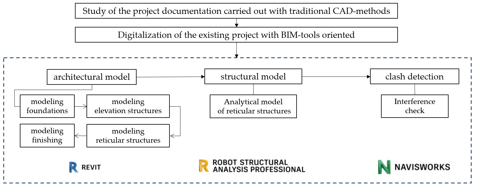
In
Figure 1, the process methodology is shown. Starting from a deepened study of the project documentation provided by GE.S.A.C. S.p.A., the IV Bridge was digitalized using Autodesk
® software; in particular, Revit
® was used for the architectural-structural model, Robot Structural Analysis
® (RSA) for the analytical verification and Naviswork
® (NW) for clash avoidance to identify if—and where or how—two parts of the building are interfering with one another. Based on the results, the final discussion and considerations were carried out.
3. Case Study
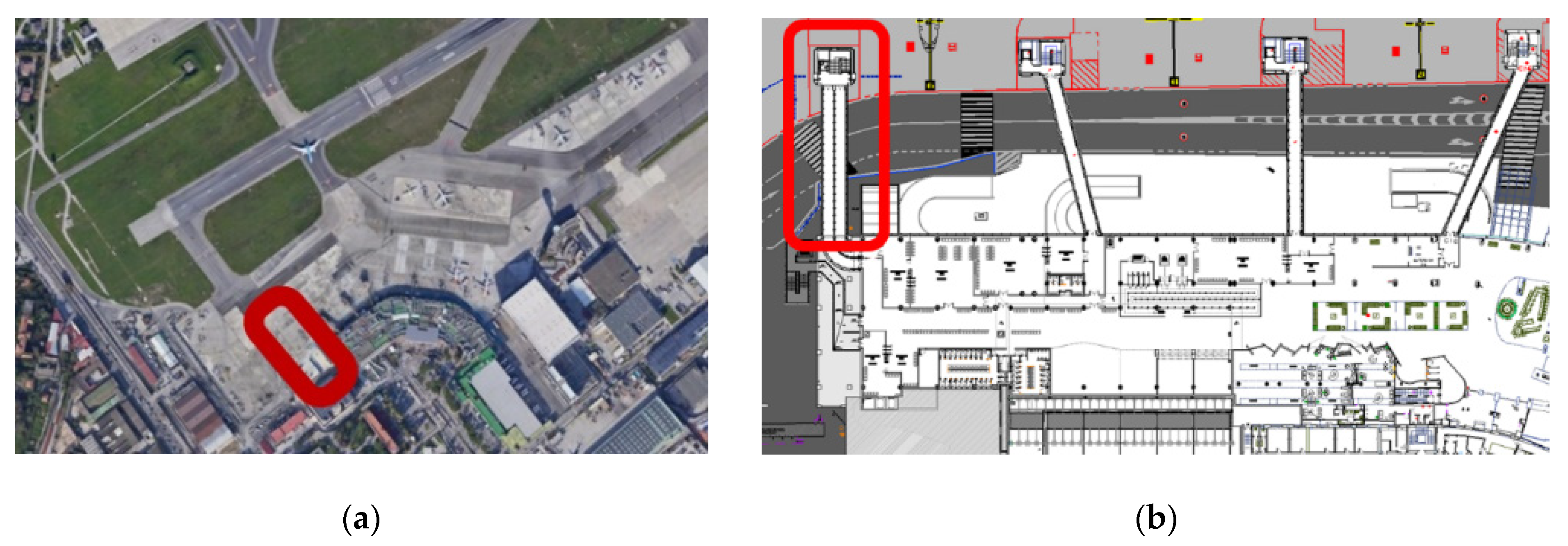
According to 2019 data, Naples Capodichino International Airport is the fifth-busiest airport in Italy and the busiest in Southern Italy [
31]. The airport is ranked class 4D based on the International Civil Aviation Organization (ICAO) requirements, and it is classified as a military airport opened to commercial air traffic 24 h/day.
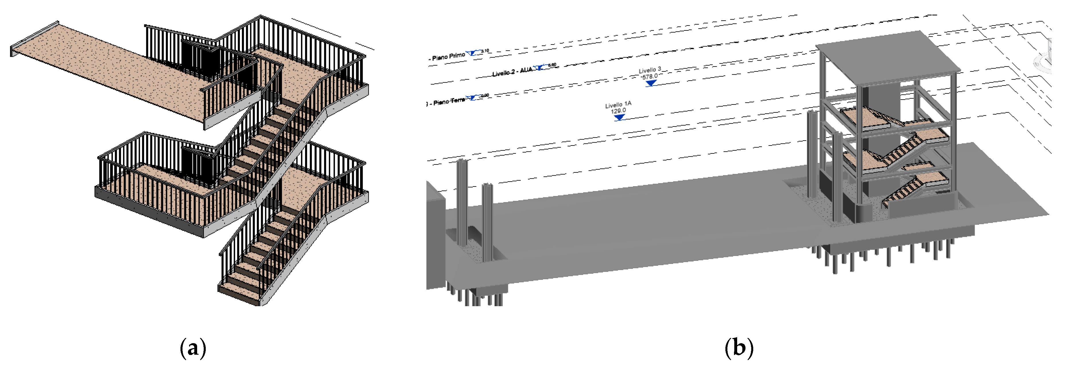
One of the interventions concerns the expansion project of the Departure Hall, part of which involves the modeling of the IV Bridge shown in
Figure 2. The bridge (first substructure) connects the existing terminal to the stairway core (second substructure).
3.1. Architectural Model
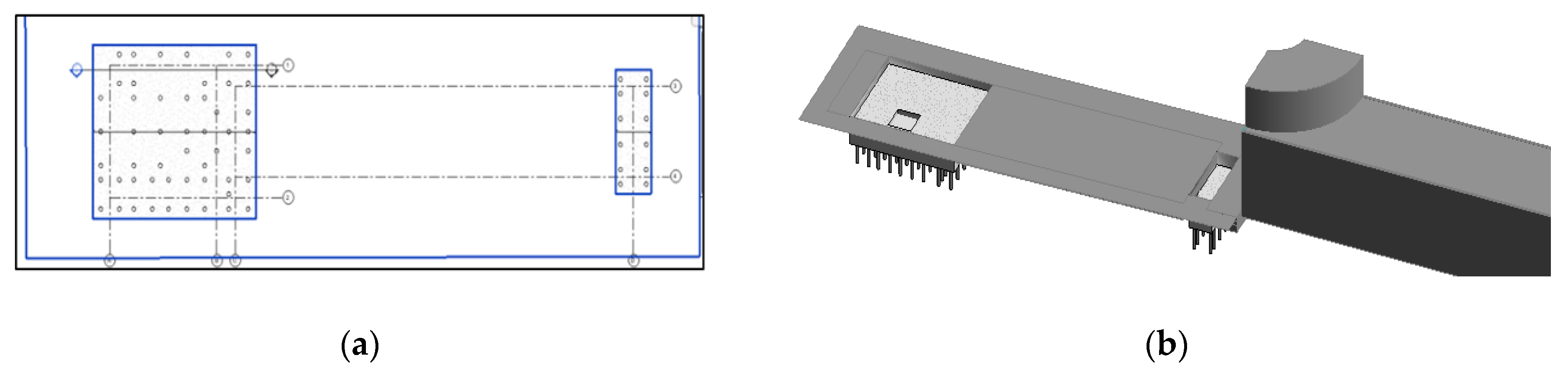
3.1.1. Modeling Foundations
Considering the sandy nature of the soil, a deep foundation was chosen with the creation of a base plinth on micropiles. The choice of micropiles was based on reducing the overall dimensions of the construction site areas since the area affected by the work is essential to guarantee the functionality of the airport and passenger service during construction. Additionally, the technology of micropiles allows contractors to limit inconvenience to airport activities as they induce minimal vibrations with minimal soil removal.
The foundation structure of the stairwell consists of reinforced concrete plinths, with plan dimensions of about 10.15 m × 9.00 m with thickness 1.40 m on micropiles with 0.25 m diameter and 15.00 m length. The pillar’s foundation structure on the right side of the bridge is made up of reinforced concrete plinths, 2.20 m × 6.43 m in size and 1.40 m thick, on micropiles with a 0.25 m diameter and 17.00 m length.
The topographic surface of the airport apron was modeled, and the materials defined. The “grids” and “levels,” where the metal carpentry will be placed, have been inserted. Subsequently, the “building platform” was inserted to level the ground, and finally the foundations in micropiles (see
Figure 3).
3.1.2. Modeling Elevation Structures
The stairwell (second substructure) connects the bridge (first substructure) to the runway. It is a compartment 6.50 m × 4.50 m inside which there is a flight of stairs, with a net width of 1.70 m.
The supporting structure consists of HEB300 beams with a steps slab with a minimum thickness of 0.10 m made of reinforced concrete and with landings made of reinforced concrete 0.18 m thick.
The only landing at bridge height is made of corrugated sheet metal in analogy to that of the footfall of the bridge itself. Inside the stairwell, there is a reinforced concrete lift core with a plan size of 2.20 m × 2.35 m, consisting of 0.20 m thick vertical walls and a 0.20 m thick roof slab.
The pillars are made of steel elements of section HEB300 reinforced with plates, while the beams have a section HEB260. The secondary frame, on which the corrugated sheet floor rests, consists of HEB300 beams.
Beams and pillars have been linked to the previously created grids and levels. The result is shown in
Figure 4.
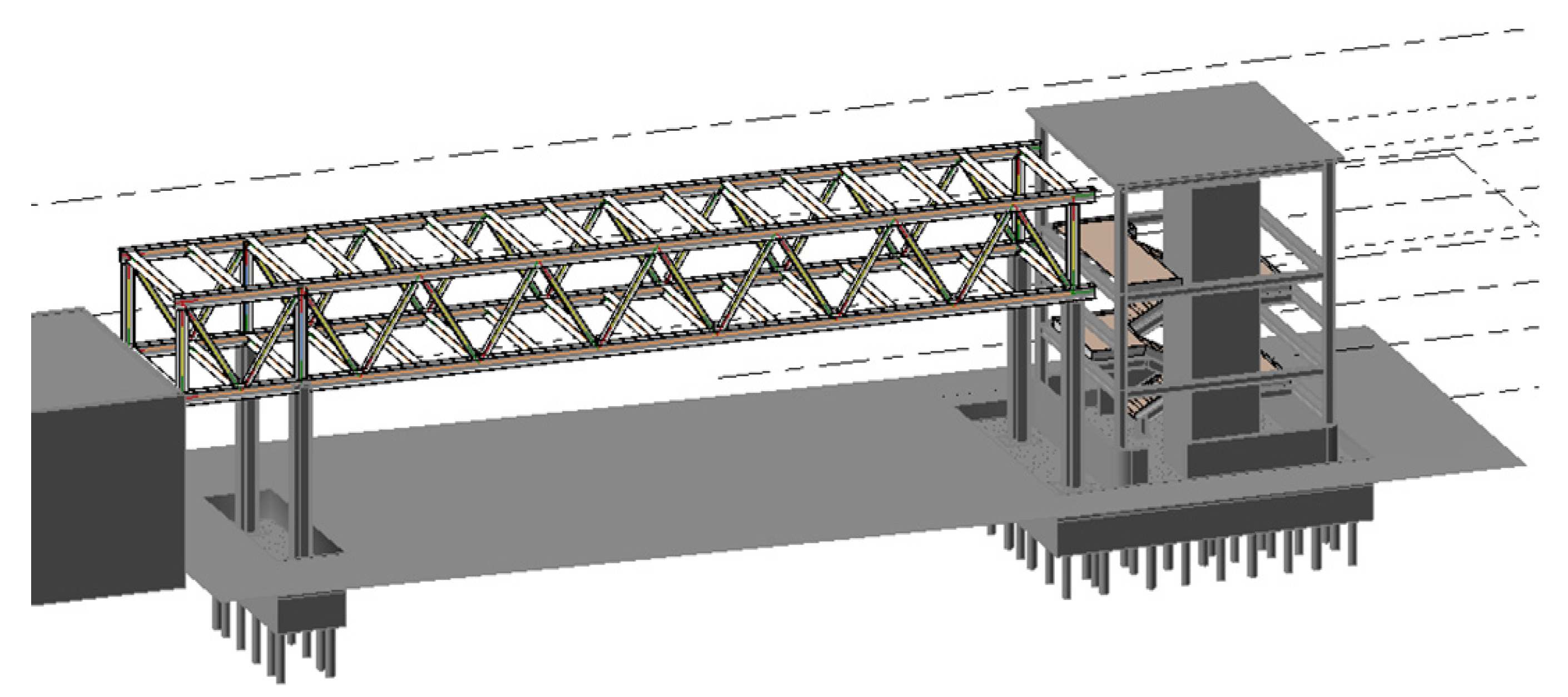
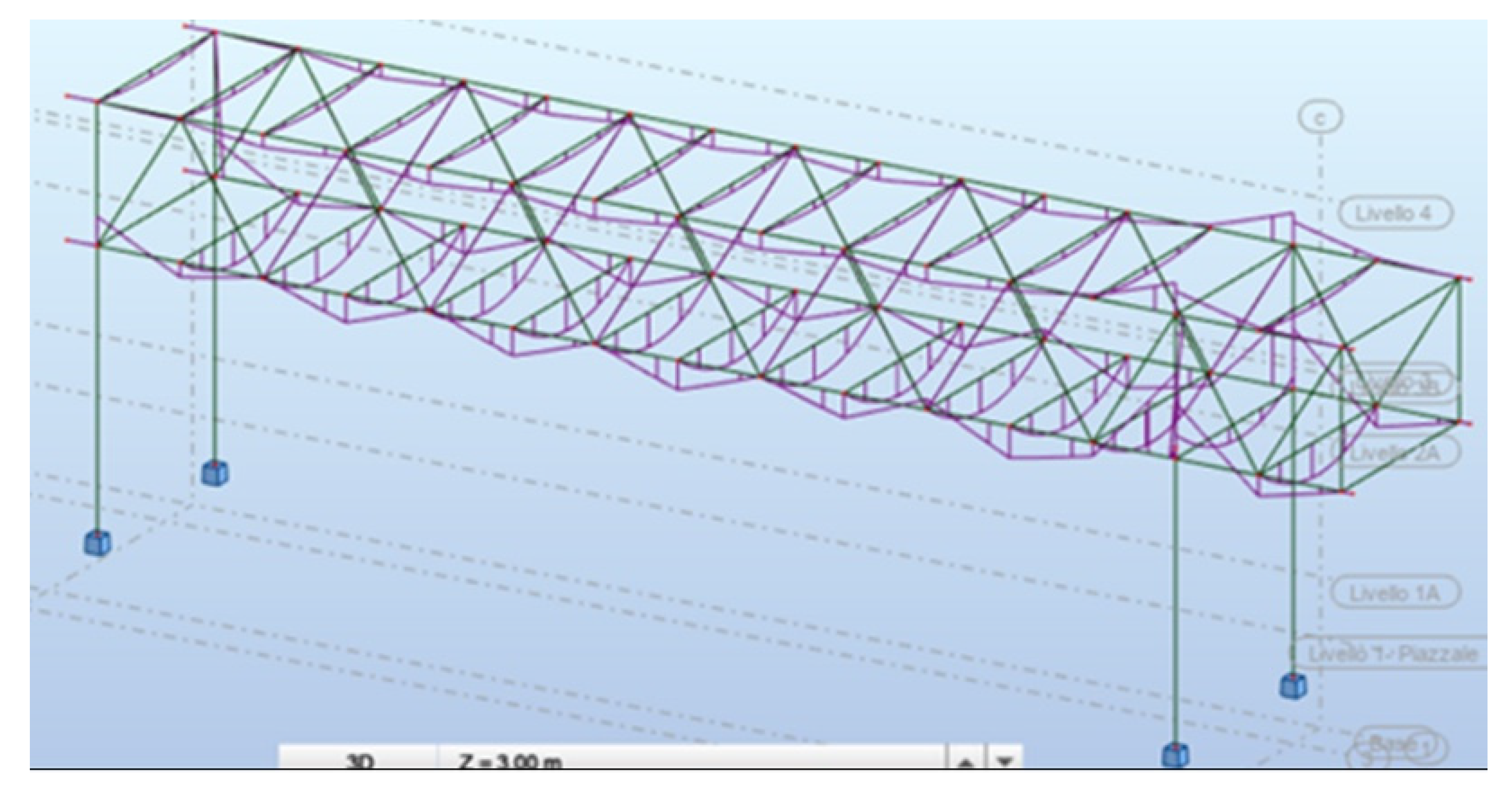
3.1.3. Modeling Reticular Structure
The bridge is a reticular metal structure consisting of a double longitudinal beam HEB400 connected by bracing consisting of HEB200. The secondary frame, on which the corrugated sheet ceiling HI-BOND A55/P 600 rests, consists of HEB300 beams.
The pillars consist of a profile consisting of a double HEM600 welded crosswise. It is a reticular metal structure consisting of a double longitudinal beam HEB400 connected by HEB200 braces.
The slab is cast on-site on corrugated sheet metal with a total thickness of 0.12 m. The reticular structure model is shown in
Figure 5.
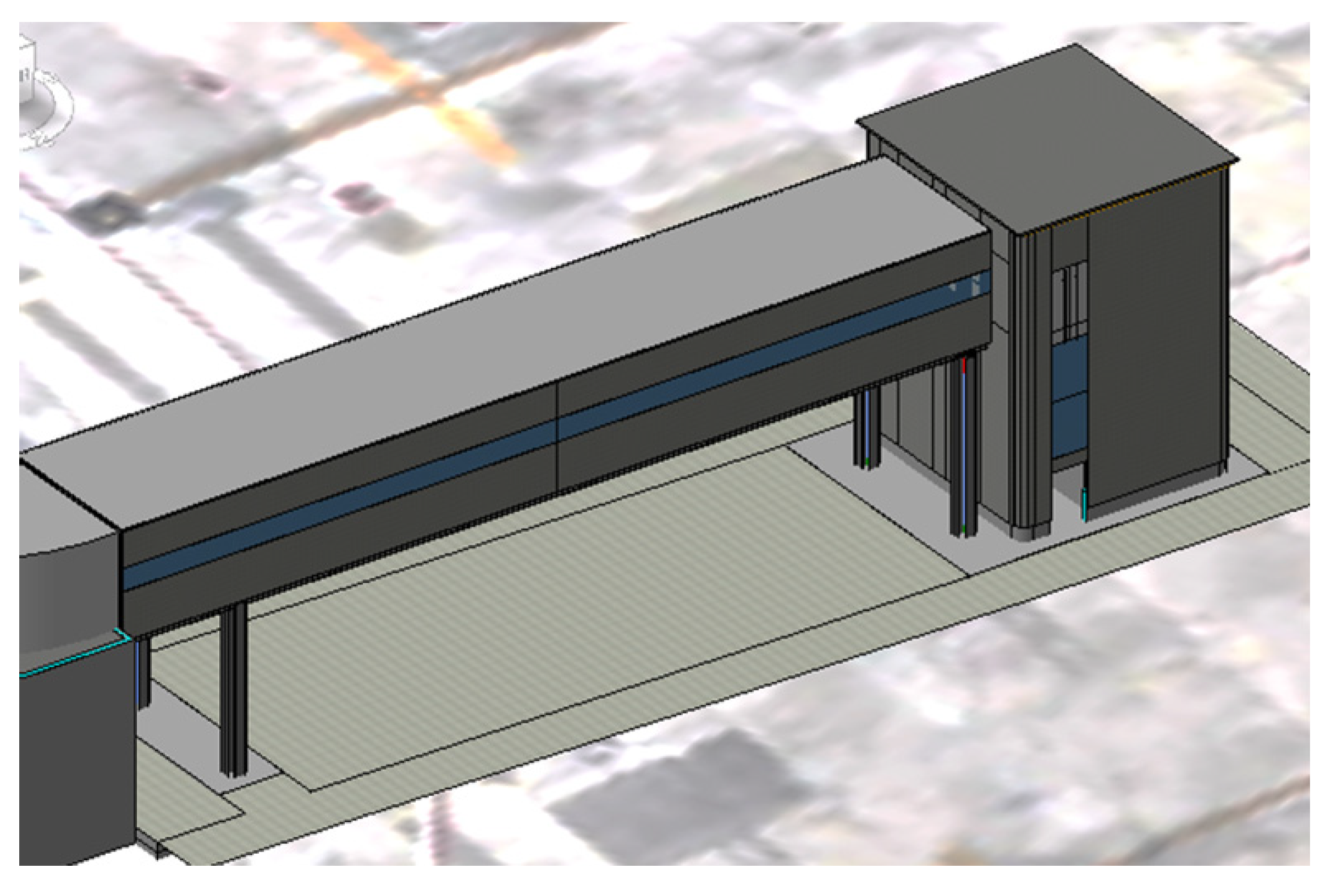
3.1.4. Modeling Architectural Finishing
The external finishes, such as paneling, windows, and doors have been modeled as shown in
Figure 6.
3.2. Structural Model
The analytical model is the representation of the physical structural model of the project, and it is made up of analytical elements characterized by a certain geometry, material properties, and loads. It is automatically generated during the creation of the physical model. The following structural elements are associated with the analytical model: structural pillars, elements of the structural frame such as beams and braces, structural floors, structural walls, and elements of the structural foundation.
The analytical model of a single structural element includes instance parameters, physical properties of materials, default position relative to the structural element, the position with respect to the projection plane at the time of insertion or adjustment.
As an example, the analytical model was built only for the reticular structure, exporting the 3D parametric model created in REVIT in the RSA calculation code. The vertical design loads were distributed over the reticular structure, calculating the moment diagram net of seismic actions as shown in
Figure 7. The accuracy of the results was confirmed by comparing them with those calculated in the design phase with traditional methods.
3.3. Clash Detection
NW software was used for cost and time analysis.
Cost planning is the most important phase to be implemented within a project, and it is contractually agreed upon in the estimated metric computation (EMC). In accordance with Italian Standards [
32], the EMC is a mandatory draft of the final and executive projects in the field of public works.
Specifically, the EMC was carried out in accordance with the following phases: classification of processes, measurement of processes, and an estimate of unit prices.
The first phase involves the “classification of processes” into homogeneous categories of work. The aim is to univocally associate the qualitative description of the process with its precise quantification (measurement) and its unit price (price list).
The second phase involves the “measurement of the processes” and it consists of assessing the exact quantity of each process necessary for the execution of the project. The third phase is the “estimate of unit prices” and it consists of attributing a unit price to each process as described and measured.
For each planned bit of work, the corresponding construction scheduled time was properly associated. In this way, it is possible for real-time navigation and accurate simulation of the work, as well as checking for interference.
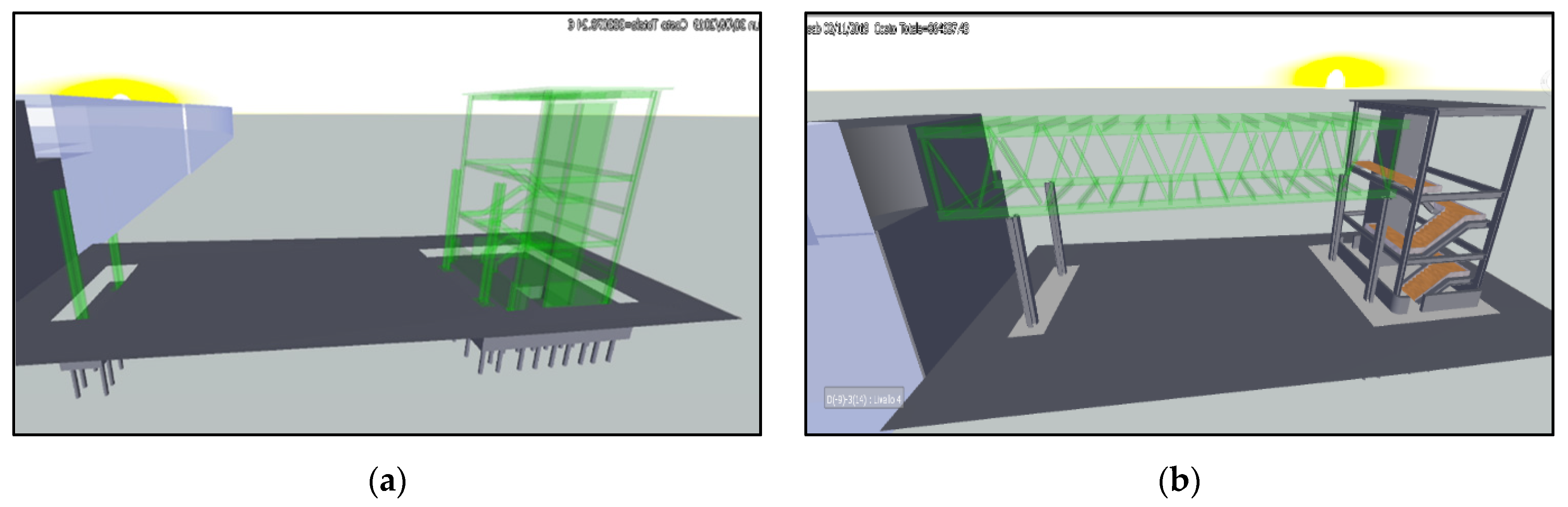
Through the “Clash Detection” tool, two types of interference were detected.
Figure 8a shows a detected interference due to the intersection between the beam and the stairwell caused by modeling errors.
Figure 8b shows interference in the form of a design error not identified in the existing executive project carried out using the traditional methods that were ultimately due to overlapping between an external wall and a base plate.
From the example, one can see that, without the use of BIM methodology, the errors would have only been recognized in the construction phase.
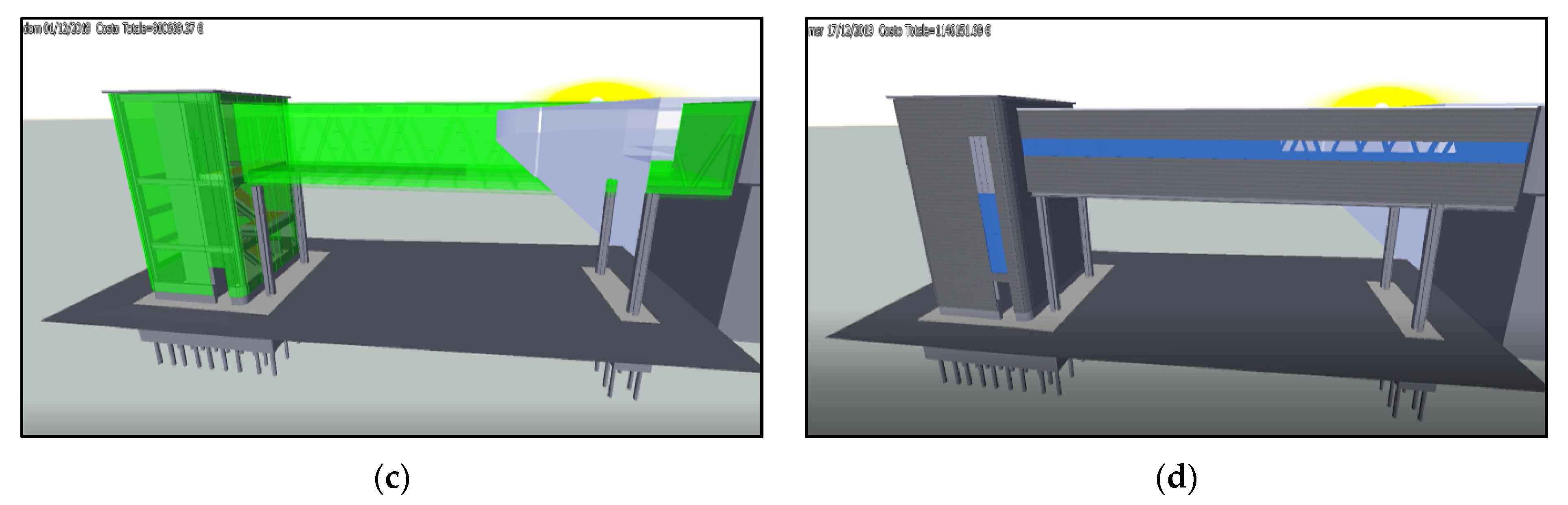
Figure 9 shows the output of the simulation at different periods within the timeline of work progress.
4. Discussion
4.1. Design Project Evolution
BIM allows one to overcome the inefficiencies typical of the traditional design method of conventional professional practices, allowing for the first time in the history of construction to achieve full integration between the design and the executive phase.
In a traditional CAD application, there are only lines and geometric figures that do not contain any type of information or relationship; the changes and variations must be made several times, and above all updated in each table. In BIM, on the other hand, drawing always remains at the center of the design process.
Each object is associated not only with geometric and dimensional values but also with all the necessary data and parametric constraints.
The use of a standard protocol allows one to interface this information with additional data—structural, plant engineering—and technical/management, calculations, estimates, work planning, cost/budget analysis, etc.—creating an organic view of the project in all its conceptual, executive, and management phases.
4.2. Cost and Time Saving
The advantages of Building Information Modeling compared to traditional project management methods are evident both in terms of optimizing operating flows and productivity.
BIM does not just expand the database contained in the three-dimensional models of the project and the possibilities for sharing them; it is precisely these advantages that have important consequences also in terms of cost optimization. Alongside the obvious time savings, the total elimination of errors, duplications, and interferences is equally important, thanks to the real-time updating of all the project tables according to the variants made, and the consequent reduction of errors and subsequent corrections.
According to the Italian Regulation on Public Works [
33], the compensation due to the executor in the event of total or partial suspension of the works is quantified based on the following criteria: a) the higher charges for non-interest bearing general expenses are obtained by subtracting the profit of the company to the extent of 10 percent and general expenses to the extent of 15 percent and calculating the percentage of 6.5 percent on the result. This result must be divided by the contractual time and multiplied by the days of suspension and constitutes the maximum limit for the compensation quantified based on the criterion set out in this letter; b) the damage to the profit is recognized to coincide with the delayed perception of the company profit, to the extent equal to the legal interest for late payment calculated on the percentage of ten percent, compared to the duration of the illegitimate suspension; c) the non-depreciation and the unnecessarily paid remuneration refer respectively to the real value, at the time of the suspension, of the existing machinery on-site and the consistency of the workforce ascertained by the works manager; d) the amortization is calculated based on the annual coefficients set by the current tax regulations.
The partial suspension of the works also determines the deferral of the contractual terms equal to several days determined by the product of the days of suspension for the ratio between the amount of the works not carried out due to the partial suspension and the total amount of the works expected in the same period according to the schedule.
As soon as the causes of the suspension have ceased, the construction manager informs the Head Project Manage so that the latter orders the resumption of the works and indicates the new contractual term.
For this reason, the possibility of identifying possible interferences already in the design phase that would occur, as it happened in the case study, are evident for considerable cost/time savings.
However, clash detection is the second best. Well managed BIM will major in clash avoidance. Clash detection is a reactive process (after-the-fact) and checks for collisions and coordination only after design decisions have been taken, while clash avoidance is a proactive process and ensures that design decisions and outcomes are agreed to collaboratively through joint design promoted with collaboration amongst the construction team [
34].
4.3. Teamwork Collaboration
Building information modeling is taking a center stage in the digital transformation of the construction industry.
However, there are significant barriers and obstacles to using BIM. The greatest resistance came from the unwillingness of practitioners to change traditional working practices [
35,
36,
37].
BIM would serve as the focal software platform for integrated design, modeling, planning, and collaboration, thereby “providing all stakeholders with a digital representation of the characteristics of a building in its whole lifecycle.” By supporting a transparent and seamless flow of information between all stakeholders (thus cutting information loss), BIM facilitates their collaboration throughout the different project phases. BIM in the EU construction sector.
Design and construction of a building involving various technical roles each operating within their area of competence. This leads to the strategic importance for the various participants to exchange information to effectively collaborate in the realization and management of a shared project.
And this is the main reason why the need to exchange a multidisciplinary data model arises using a standard file format, allowing secure interoperability and interchange of data without introducing errors and/or loss of information. To be able to work collaboratively, the different actors need more than just the ability to transfer information, they need to have the ability to transfer meaning when referring to a common information exchange reference model. This is the true purpose of having the Industry Foundation Classes (IFC) data format.
Working with a BIM on the virtual model makes a shared and collaborative approach among all the professionals involved more convenient, compared to the more traditional “sequential” process characterized by additions and corrections, both in the design and construction phases.
The design effort concentrated in the initial stages of the design (typical of an integrated approach) has a positive impact in terms of costs (reduction), compared to what we usually see in reality, where the traditional process sees completion and the improvement of the project in more advanced stages with much higher costs [
38].
It is not a question, as is evident, of reducing the project “efforts,” as the commitment can only be commensurate with the quality of what is intended to be achieved (the maximum points of the two representative curves of the BIM-oriented and traditional processes they are almost identical), but to anticipate these efforts over time.
Therefore, a new way of approaching design comes to life, the result of its “technical practicability” made possible by the availability of the virtual model of the building, but above all the economic convenience resulting from its implementation. The convenience is clear by analyzing the trend of the curve relating to the costs of the design changes, which are gradually lower when the corrections and additions are anticipated.
Starting, therefore, from the prototype, new collaborative processes are taking shape thanks to the BIM methodology, which requires the co-presence of all the actors in the design and, hopefully, also in the implementation, right from the earliest stages of the design of the building intervention.
4.4. BIM Golden Thread
The use of BIM during the asset lifecycle including on-site activities, facility management, and EOL management would enable the valuation of blue-collar professions and establish continuity in the use of new technologies. All the stakeholders involved in the asset lifecycle will be able to enter the revolution brought by BIM in the construction sector. Blue-collar professions would become more attractive, and then the shortage of workers could be fixed [
39].
The Building Information Model is critical to the golden thread—a digital model that all people involved in the project can work on, from the architect to the client. It is the digital description of every aspect of the built asset. The model draws on information assembled collaboratively and updated at key stages of the project. While the model is a visual representation of the building, there are other assets linked to it, such as technical specifications, construction, and asset management information. This is all hosted in what is called the Common Data Environment (CDE): the place which collects, manages, and disseminates documents. It is where the graphical model and all associated written data (such as spec, installation, maintenance information) is stored. There are currently gaps around handover, running/maintaining, renovating, and demolishing the building. There are usually no records at these phases, or if there are, they are not joined-up.
Government intervention around the golden thread will accelerate things further. The Government has new building safety measures proposed which includes achieving the golden thread, in part through the implementation of BIM.
The government expects that the golden thread will require the use of a common data environment that will allow different parties to work collaboratively on developing and maintaining the information.
4.5. Social Changing Process
Whereas it is a technological innovation, BIM has been linked not only to the coordination of technological artifacts, but also to the coordination of complex sociotechnical processes to align heterogeneous actors and information [
40,
41] across projects, networks, and markets.
Various governments throughout the world have adopted strategies aimed at increasing local BIM take-up in the industry.
As an example, the UK government adopted a “Push-Pull” strategy. The government “pulls” the industry towards BIM adoption by requiring that all public projects be delivered through BIM, enabling access to the design, costs, and performance of the asset throughout its lifecycle. The “push” element, on the other hand, is expected to be carried out by the industry. The industry is to be responsible for the adoption and utilization of BIM by providing standardization, information, training, development, and infrastructure. This leaves the free market to be able to determine BIM best practices and have the freedom to constantly develop new solutions [
42].
In the same way, in Italy, the government [
18] “pulls” the use of BIM as a mandatory in the huge projects and gradually will extend its use to all the projects regardless of its relevance.
Rather than creating new jobs, there is an evolution of the world of work linked to construction and the conversion of many existing jobs with the introduction of new managerial figures [
18]:
BIM Specialist: that is the one who uses the software for the realization of a BIM project;
BIM Coordinator: which manages and coordinates BIM projects on one or more specific disciplines (for example architecture, structures, plants, etc.);
BIM Manager: who not only manages and coordinates BIM projects but is also responsible for managing and coordinating information for suppliers involved in the design, construction, and management of the work.
The search by companies for professional figures with skills able to align with current and future scenarios is the sign of a strong change taking place. To not to miss the challenge, the companies themselves will have to acquire the know-how necessary to make the most of the many opportunities that BIM is offering.
In this scenario, the collaboration between Industry Sector and University are commonplace establishing joined program such as Second Level Master’s degree, Training course, Job opportunities for students to train the current/future generations in using BIM properly.
It is also important to investigate how to reduce the gap between EU countries in BIM implementation to open new market opportunities across the EU working to the same standards so that all companies can engage and work effectively with partners within the EU without any problem [
43].
5. Conclusions
In this case study, the potential benefits from using a single, integrated model of the various professional disciplines and the ease of updating the project tables in real-time according to the changes made, were evaluated.
Creating projects supported by BIM tools brings many benefits. Thanks to the parameterization, the number of variants of the solution can be increased by reducing the design time. Thus, choosing the most optimized solution.
The analysis of the interferences allowed designers to identify an error present in the executive project with traditional methods, due to the overlap of an external wall with a base plate of a pillar. The preventive identification of the interference would allow a considerable saving of both the time and costs of carrying out the work. Therefore, BIM can help overcome the typical inefficiencies of the traditional design method and conventional professional practices, allowing more full integration between the design and the execution phases.
BIM overcomes these shortcomings by embracing information mobility and making everyone use the same set of standards and processes. As a result, asset knowledge consistently increases over the lifecycle of the project. Implementing BIM enables architects/engineers to make informed design choices, and it allows constructors to minimize waste and complete their projects on time, saving on expenses incurred due to avoidable delays.
With BIM-tools it can be analyzed and verified all the design aspects of a building with a consequent time needed to make changes to the project drastically reduced. Every modification made to the model affects every aspect of the design and the collaboration between different professional figures (engineer, designer of systems, structures, architectural, energy) becomes very easy sharing the same way of processing information.
Furthermore, regarding future developments, the implementation of the “BIM” method with an integrated model of the plant design and 6D and 7D BIM models will allow optimal management of the infrastructure assets.

 ,
, 


