Abstract
In this paper, experimental and numerical results of a research project about the structural behavior of strengthened masonry are presented and discussed. The aim of the research is to study the in-plane shear behavior of an old masonry wall with an opening in the arch form, reinforced with a pioneering system of 3D pre-tensioned stainless steel ties. The masonry wall was in-plane loaded until first cracking appeared, then it was reinforced and re-loaded until failure. The experimental results have highlighted the benefits of the reinforcing method adopted, especially to provide an increasing in terms of both strength and ductility. Numerical modeling of the masonry wall behavior was accomplished by using non-linear finite-element methods generally adopted for reinforced concrete elements.
1. Introduction
Existing unreinforced masonry (URM) structures are commonly characterized by poor mechanical properties of both stones and mortar. Therefore, their maintenance condition is usually precarious and, consequently, their seismic performance is unsatisfactory. Generally, brittle failure is expected [1].
Because many masonry buildings are part of built heritage, especially in the Mediterranean area (Italy, Spain, Portugal, and Greece), there is a comprehensive interest in and attention to investigating new strengthening and repairing techniques, aimed at improving the response behavior of URM elements against seismic actions [2,3,4,5].
For the retrofitting of URM buildings, several methods are used in different countries. Some of these are also prevalent in others, for example the use of concrete or mortar stratum on the masonry surface, or using a plastic or steel mesh [6]. In this case, the resistance capacity of the masonry is enhanced, but also the thickness is enlarged, and as a consequence the stiffness variation should be a focus of attention.
More recently, this weakness of the reinforcement method has been overcome by using different materials with high constitutive properties. Therefore, under the same conditions, the thickness of the reinforcement is strongly reduced. In this research field, several alternatives have been investigated, such as the use of steel fibers in the concrete or the mortar mixture to obtain an equivalent material with large strength in tension [7]; contextually, the use of fiber-reinforced polymers (FRP) or of fiber-reinforced cementitious matrix (FRCM) differs from the matrix-embedding material (resin or mortar) [8,9,10,11]. These approaches allow the obtaining of a reinforcement material with excellent mechanical properties.
However, these reinforcement techniques may have some drawbacks, such as poor fire resistance and delamination vulnerability [12]. In addition, for masonry with very poor mechanical properties, the use of FRP cannot provide enough increase in terms of strength and, especially, deformation capacity to satisfy the requested design performance [3].
Therefore, a different methodology of reinforcement has been proposed based on the use of stainless steel as external reinforcement [3,13].
Stainless steel ties wrap the masonry in a three-dimensional “package”. This provides a high confinement of the Reinforced Masonry (RM), improving both flexural and shear strength. In this case, the main drawbacks are the mechanical properties and the durability of the stainless steel, and the technology of the mutual connection of ties [14,15].
To overcome these issues, an experiments have been carried out to study the capacity of a reinforcement system, namely Active Confinement of Masonry or Manufacts (CAM), to improve the low performance of URM and reinforced concrete (RC) structural elements. The use of stainless steel avoids any durability concerns at the time. Moreover, the ties are pre-tensioned to induce a confinement effect on the masonry. A special joint device allows the realizing of a continuous tying system, wrapped all around the masonry element [16,17,18].
Among the tests carried out in situ, a full-scale wall was obtained from an existing building, and tested to study the cracking behavior of the URM. Then, the wall was reinforced with CAM. At that point, the wall was re-tested to estimate the effect of the reinforcement system on the wall response behavior [18].
As observed, the analyzed reinforcement technique has been helpful in improving out-of-plane connections between masonry layers, and in increasing the in-plane strength and ductility.
Another issue regards the modeling of the non-linear response behavior of masonry structure subjected to in-plane horizontal load. Several analytical procedures have been proposed in the literature to reproduce the response behavior of RC walls. Among these, the Finite-Element Model (FEM) based on a smeared approach, namely Disturbed Stress Field Model (DSFM), has been suitably adapted to the URM and RM wall. The predicted results are analyzed and verified against the experimental ones.
2. Test Setup
The masonry wall under test was part of an old building scheduled to be demolished. As it is a real wall, and not a laboratory sample, the geometric shape was not really ordered. The wall was almost an elevation square—4450 × 4600 mm—and the average thickness was 700 mm. The piers were of tetragonal shape: the left one had width of 950 mm; the right was 1200 mm; the base of the arch-shaped opening was 2300 mm wide. Also, the wall was characterized by poor-quality masonry with different-sized stones and mortar of friable lime (Figure 1a).
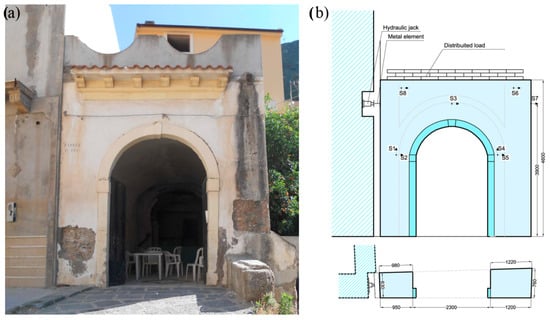
Figure 1.
(a) URM wall and (b) test setup [18].
To prepare the wall for test, the following steps were followed: (1) the external surface of the wall was manually scratched to eliminate the old plaster; (2) the balustrade at the top was demolished; (3) the wall was cut from the rest of the structure by a band saw; and (4) the wall was layered with external plaster (less than 5 mm), with a resistance to average compression of 5 MPa.
To obtain a stationary reference for the measurements, a steel frame was built close to the wall, and eight linear variable displacement transducers (LVDTs: S1–S8) were used (Figure 1b).
At the second test step, the same wall was reinforced using two-stripe mesh stainless steel.
The pseudo-static lateral load (P) was applied using a hydraulic jack and constrained against an adjacent building with higher mass and stiffness than the tested wall.
A hydraulic jack was used for the first test on the URM wall with capacity 200 kN and an available displacement of 50 mm. For testing the RM wall, a hydraulic jack with a capacity of 1000 kN and an available displacement of 100 mm was used.
Furthermore, a constant compression (N) equal to 7 kN/m was applied. This distributed load has been applied to partially reproduce the compression stress due to the vertical loads.
3. Materials Properties
3.1. Stainless Steel
The CAM system is mainly composed of stainless steel ribbons. Their mechanical characterization is needed.
The adopted stainless steel tie was 0.9–1 mm thick and 19 mm wide, with yielding (fys) and ultimate (fts) strength in the range between 220–500 and 540–850 MPa, respectively. The variation in the mechanical properties is due to the different types of stainless steel that can be used. In this case, the average experimental yield strength and elastic modulus were equal to 316 MPa and 221 GPa, respectively.
Moreover, the connection devices were 125 × 125 × 4 mm in size.
In Figure 2, a typical arrangement for a masonry wall is shown. It is worth highlighting the need of carry out a special joint devices to realize a continuous tying system, running all around the masonry wall. For this aim, a specific pneumatic device is used, which is also able to provide a slight pre-tension of the tie.
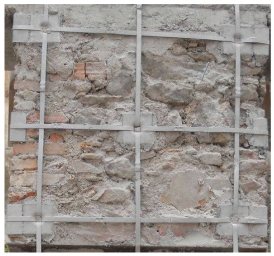
Figure 2.
Stainless steel ties arrangement in a masonry wall [18].
3.2. Masonry
To achieve information about the mechanical characteristics of the masonry in compression, a double flat-jack test was carried out.
The use of the flat-jack is valid for brick or regular stone masonry in general. In the case of rubble stone masonry, data must be extrapolated.
For the double flat-jack test, a wall of the same building was chosen and the test was carried out without stopping the flat-jack loading.
As shown by the black curve in Figure 3, the test results provided a maximum compression strength (fmm) of 1.90 MPa, and the first crack appeared at a stress of about 1.30 MPa.
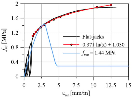
Figure 3.
Experimental and numerical stress–strain curves for masonry in compression.
Generally, the compressive strength of the masonry can be estimated as the stress reached the strain level of 3 mm/m, then a logarithmic curve (the red line in Figure 3) was adopted to fit the non-linear region of the envelope loading cycles, as suggested by Lombillo et al. [19]. Then, the maximum stress of 1.44 MPa was calculated and used in the numerical analyses.
4. Experimental Results
4.1. URM Wall
Since this is an experimental campaign in situ, on an existing building, it was possible to perform tests only on a single available wall. Therefore, the first test was performed on the URM wall to obtain valuable information on the cracking load.
Moreover, maintaining the element in a substantially elastic field has avoided inducing states of stress or strains that affect the next test.
Several load cycles were applied and augmented until the first crack. The first cracks were observed: (a) on the left side of the wall; (b) near the top of the wall; and (c) near the loading point.
The experimental cracking load was 50.6 kN, and was reached at a horizontal displacement (S7) of 5.4 mm with a trend of quasi-linear load–displacement curve. The left side of the wall was in tension, while the right side was in compression, as predicted (Figure 4).

Figure 4.
URM wall cracking: (a) left pier above the opening; (b) horizontal spandrel on the top; and (c) near the loading point.
During all load cycles, the cracks closed again. However, the load increase was interrupted to avoid a premature failure of the wall.
4.2. RM Wall
Two overlapping stainless steel ties were used to obtain the arrangement shown in Figure 5. The design of CAM was performed by a linear analysis on an equivalent frame model, assuming both vertical and horizontal loads [20].
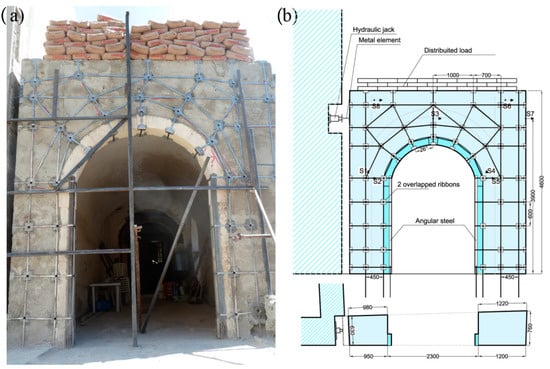
Figure 5.
RM wall: (a) original condition; (b) geometry and LVDTs position [11].
First, the seismic weight of the structure was estimated as 167.5 kN. Then, the dimensionless seismic acceleration at Ultimate Limit State (ULS) was assumed to be equal to 0.340 [21], then the pseudo-static load was PE = 57 kN.
The layout of the tapes along the piers followed a regular pattern, while a radial arrangement was adopted for the spandrel zone. The radial ties were placed orthogonally to the arch opening to surround the masonry along the directions in the plane and out of plane when subjected to horizontal loading. Furthermore, four steel corner pieces (40 × 40 × 4 mm) were used to reinforce the inner edges of each piers improving its bending capacity (Figure 5). The anchorage at the base of the wall was carried out by inserting part of tie into the ground and folding into a noose by using a high-strength mortar.
The load (Pm) of 111.1 kN was recorded, and the lateral displacement (δm) was about 50 mm. The displacement of the RM wall was higher than the capacity of the hydraulic jack, such as shown in Figure 6a; however, failure of the wall was not achieved. With the goal of evaluating the strength of the RM wall, the structure was un-loaded and then a new hydraulic jack with a wider stroke was used. Therefore, a new part of the load–displacement curve (P-δ) was performed, reaching a maximum displacement of 70 mm, but without the collapse of the wall. The load remained almost constant for different load cycles until cracks were determined to have a negative stiffness during the last load cycles.
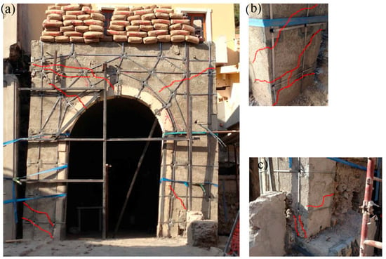
Figure 6.
RM wall: (a) crack pattern; (b) left; and (c) right pier.
At maximum load, both lower parts of the left and right masonry piers were in traction and with wide cracks, producing plastic hinges and allowing a wide horizontal displacement of the upper part of wall (Figure 6b,c). Different cracks appeared on the upper part of the wall and extensive cracking was observed on the whole wall.
This is thanks to the ability of CAM to confine masonry, allowing the stress bridging through the crack sides and the spread of stresses over the whole the wall.
5. Numerical Analysis
Several theoretical works about the response modeling of masonry structures subjected to different load conditions have been presented in the literature. The simplest models are based on elasticity assumption and, when studying the behavior of the masonry subject to load levels up to 30–50% of the collapse load, its use provides good results.
On the contrary, to get valuable information on ULS behavior, non-linear modeling is needed, and the cracking phase must necessarily be considered.
In this situation, FEMs could be useful. In fact, the masonry is generally composed of stone units and mortar, so numerical modeling is certainly a challenge.
There are several methods proposed and based on macro-element discretization; see Magenes [22], Chen et al. [23], Yi et al. [24]. In this study, each part of the structure, piers and spandrel, is modeled by using a truss or beam.
These finite elements are certainly suitable for the design phase and for the evaluation of masonry structures thanks to their straightforwardness of use and the accurateness demonstrated in several contexts.
A different way to reproduce the response behavior of the masonry is the use of FEM, capable of modeling the stress field considering the mechanical properties of materials. Recently, Mojsilovic et al. [25] have put forward a way of modeling based on stress field based on the theory of plasticity, using elasto-plastic constitutive laws, and demonstrating a good efficiency and reliability in the case of RM. However, the proposal of Mojsilovic et al. [18] neglects the tensile strength of the masonry, therefore it does not reproduce with enough accuracy the response behavior in the case of URM wall.
To overcome this drawback, a different theoretical model was used in this work, originally developed for RC elements [26,27] and implemented in VecTor2 software [28]. The Modified Compression Field Theory (MCFT) considers the constitutive behavior of the different materials along the principal directions.
As described above, the wall was of masonry with low mechanical properties, both for its consistency and for the bad quality of the mortar.
Therefore, strength and stiffness of the resulting material were rather homogeneous, thus it was decided to directly use the mechanical formulation of the MCFT for RC elements, in order to duplicate the experimental behavior of the masonry wall, both without and with reinforcement.
5.1. Theoretical Constitutive Laws and Confinement Effect
The tension–strain laws in compression for the masonry are comparable to those for concrete and can be modeled by analogous equations. As suggested by Facconi et al. [29], the formulation proposed by Hoshikuma et al. [30] can be used.
The average compressive strength (fmm) was assumed to be 1.44 MPa, as obtained from testing with a double flat-jack carried out on a wall of the same structure. The constitutive behavior of traction masonry is described by an initial linear-elastic phase until the main stress (fm1) is equal to the tensile strength (fmt). It was assumed that tensile strength of the masonry was 1/30 (fmt = 0.048 MPa) of the average compressive strength [31].
The constitutive behavior of stainless steel was reproduced with a bilinear function. It is described by a linear-elastic ascending phase up to the yield (fsy), then a second linear hardening branch is typical of the tensile behavior of stainless steel up to failure (fst). As described above, the stainless steel ties can provide a masonry confinement only in the case of tensile stress; then, in compression, the reinforcement stress is zero. The yield strength and elastic modulus in the numerical analysis were assumed equal to the obtained experimental values: 316 MPa and 221 GPa, respectively.
The tri-axial stress state was considered in computing the strength enhancement effects due to confinement.
The stress (fsz) in the out-of-plane reinforcement was determined as follows:
fsz = Es εmz ≤ fsy
The out-of-plane masonry compressive stress (fmz) was estimated from equilibrium equation:
fmz = −ρsz fsz
5.2. Results
The mesh used for the masonry wall consisted of quadrangular and triangular elements having nodes with two degrees of freedom and uniform thickness (t = 700 mm). The stainless steel ribbons were modeled by homogenizing strength and stiffness with masonry. Furthermore, the mesh was divided into regions according to the geometrical percentage (ρ) and inclination of the reinforcement [20].
Following the experimental setup, the supports were assumed able to prevent any translations.
Numerical analyses were performed by assigning two different load cases: a static self-weight on all the masonry elements; and a monotonic displacement, coaxial with the lateral load. The experimental test was carried out by loading and unloading the specimen, but for numerical modeling only the monotonically behavior was considered. It is a simplification of the response behavior to check the reliability of the used model. In further research, a load–unload pattern, coupled with a damage model for the masonry, could be used to achieve a better prediction of the experimental test results.
The total load was calculated as the reaction force of horizontal constraints.
Figure 7 shows the experimental and numerical curves of load–displacement in the conditions of without (a) and with (b) reinforcement. The comparison between the curves highlights the capability of the theoretical model to reproduce the experimental response. In Figure 7a the load–displacement curve up to the first crack for the URM wall is plotted. The analytical model estimates a cracking load value similar to the experimental one. The percentage error is 5% and 15%, respectively, for the load and the displacement of first cracking.
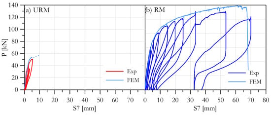
Figure 7.
Experimental and numerical curves for the (a) URM and (b) RM wall.
The first cracks appeared at the left side of the wall, as observed experimentally.
Figure 7b shows the load–displacement curves for the wall reinforced with CAM. The results of the numerical analysis are satisfactory both in terms of final load and last displacement. The numerical curve matches the envelope of the experimental one with enough precision.
Unlike the experimental curve, the analytical curve shows a growing trend. The cause of this can be associated with analytical constitutive law used for stainless steel reinforcement.
The cracked regions of the RM, as obtained from the numerical model, correspond to those observed experimentally. All numerical curves show the capacity of the model to capture the experimental stiffness and to estimate the bearing load and the last displacement.
In Figure 8 and Figure 9, the analytical crack pattern of URM and RM wall, respectively, is shown. The first cracks are expected in the correspondence of the left side of the wall and at the base of the pier, as experimentally detected. The masonry is cracked at both piers and all over the wall. The analytical curves highlight the capability of the model to provide the load capacity and the ultimate displacement due to CAM.
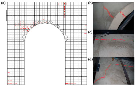
Figure 8.
First cracks on URM wall: (a) numerical crack patterns; (b) left haunch of the arch opening; (c) long horizontal crack close to the top left of the wall; and (d) crack close to the point load.
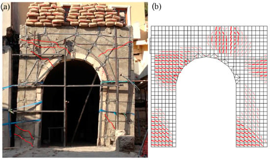
Figure 9.
(a) Experimental and (b) numerical crack patterns for the RM wall.
6. Conclusions
In this paper, part of the results of an experimental campaign were presented and discussed regarding the reinforcement of ancient walls in Messina (Italy) via CAM system.
A wall was cut from an existing masonry structure to carry out shear-compression tests. Furthermore, analytical analyses were used to predict the experimental responses of URM and RM walls.
By the results of tests and analytical studies, it is possible to draw the following conclusions:
- Higher strength and ductility were observed due to reinforcement.
- CAM helps to improve the connection between the layers of masonry and upturns the resistance and ductility in the plan, as well as the quality of connections between adjacent walls.
- The elements that make up the reinforcement system are easy to install and they can be integrated well into the general context; however this reinforcement method is based on a minimally invasive technology, hence its use on historic buildings must be assessed case by case.
- FEM analyses gave a good prediction of behavior of the wall subject to horizontal and vertical actions, displaying the capacity of the numerical model to reproduce well both the ductile and brittle failure mode of the wall. The crack patterns were carefully reproduced.
The experimental results have highlighted how CAM needs an optimization to obtain the ductility and the ultimate design load. For this purpose, the numerical procedure adopted herein should first be improved to take into account the cyclic nature of load, and then it could be used by changing the parameters and the geometric characteristics of CAM, for the purpose of analytically evaluating the ribbon arrangement which provides better performance.
Author Contributions
These authors contributed equally to this work. All authors have read and agreed to the published version of the manuscript.
Funding
The financial support from the Italian Ministry of Education, University and Research (PRIN Grant 2015HZ24KH—“Failure mechanisms caused by corrosive degrade and by lack of constructive details in the existing structures in reinforced concrete”) is gratefully acknowledged. The corresponding author wishes to express his personal gratitude to this research fund and also to the PRIN Grant 2015HZ24KH, through which a research fellow scholarship was awarded.
Conflicts of Interest
The authors declare no conflict of interest.
References
- Recupero, A.; Spinella, N. Strengthening of a Masonry Wall in Seismic Prone Area with the CAM System: Experimental and Numerical Results. In Proceedings of the 8th Euro-American Congress REHABEND, Granada, Spain, 24–27 March 2020. [Google Scholar]
- Todisco, L.; Stocks, E.; León, J.; Corres, H. Enhancing the Structural Performance of Masonry Structures by Post-Tensioning. Nexus Netw. J. 2018, 1–21. [Google Scholar] [CrossRef]
- Corradi, M.; Di Schino, A.; Borri, A.; Rufini, R. A review of the use of stainless steel for masonry repair and reinforcement. Constr. Build. Mater. 2018, 181, 335–346. [Google Scholar] [CrossRef]
- Orduña, A. Non-linear static analysis of rigid block models for structural assessment of ancient masonry constructions. Int. J. Solids Struct. 2017, 128, 23–35. [Google Scholar] [CrossRef]
- Preciado, A.; Sperbeck, S.T. Failure analysis and performance of compact and slender carved stone walls under compression and seismic loading by the FEM approach. Eng. Fail. Anal. 2019, 96, 508–524. [Google Scholar] [CrossRef]
- Shabdin, M.; Attari, N.K.A.; Zargaran, M. Experimental study on seismic behavior of Un-Reinforced Masonry (URM) brick walls strengthened with shotcrete. Bull. Earthq. Eng. 2018, 1–26. [Google Scholar] [CrossRef]
- Facconi, L.; Conforti, A.; Minelli, F.; Plizzari, G.A. Improving shear strength of unreinforced masonry walls by nano-reinforced fibrous mortar coating. Mater. Struct. Constr. 2015, 48, 2557–2574. [Google Scholar] [CrossRef]
- Borri, A.; Castori, G.; Corradi, M. Intrados strengthening of brick masonry arches with composite materials. Compos. Part B Eng. 2011, 42, 1164–1172. [Google Scholar] [CrossRef]
- Corradi, M.; Borri, A.; Castori, G.; Sisti, R. Shear strengthening of wall panels through jacketing with cement mortar reinforced by GFRP grids. Compos. Part B Eng. 2014, 64, 33–42. [Google Scholar] [CrossRef]
- Colajanni, P.; La Mendola, L.; Recupero, A.; Spinella, N. Stress field model for strengthening of shear-flexure critical RC beams. J. Compos. Constr. 2017, 21. [Google Scholar] [CrossRef]
- Spinella, N. Modeling of Shear Behavior of Reinforced Concrete Beams Strengthened with FRP. Compos. Struct. 2019. [Google Scholar] [CrossRef]
- Urso, S.; Recupero, A.; Spinella, N. Investigation of the environmental conditions effect on bond behaviour of FRP applied on concrete substrate. In Proceedings of the 1° Fib Italy YMG Symposium on Concrete and Concrete Structures; Del Zoppo, M., Colombo, I.G., Vecchi, F., Eds.; Fédération Internationale du Béton (FIB): Parma, Italy, 2019; pp. 131–138. [Google Scholar]
- Bartoli, G.; Betti, M.; Stavroulakis, G.; Stavroulaki, M. Strengthening of masonry using metal reinforcement: A parametric numerical investigation. In Proceedings of the International Conference on Protection of Historical Buildings (PROHITECH), Rome, Italy, 21–24 June 2009. [Google Scholar]
- Dolce, M.; Nigro, D.; Ponzo, F.; Marnetto, R. The CAM System for the Retrofit of Masonry Structures. In Proceedings of the 7th International Seminar on Seismic Isolation, Passive Energy Dissipation and Active Control of Vibrations of Structures, Assisi, Italy, 2–5 October 2001. [Google Scholar]
- Dolce, M.; Cacosso, A.; Ponzo, F.C.; Marnetto, R. New Technologies for the Structural Rehabilitation of Masonry Constructions: Concept, Experimental Validation and Application of the Cam. In Proceedings of the Intervention On Built Heritage: Conservation and Rehabilitation Practices, Porto, Portugal, 2–4 October 2002. [Google Scholar]
- Colajanni, P.; Recupero, A.; Spinella, N. Increasing the flexural capacity of RC beams using steel angles and pre-tensioned stainless steel ribbons. Struct. Concr. 2016, 17, 848–857. [Google Scholar] [CrossRef]
- Colajanni, P.; Recupero, A.; Spinella, N. Increasing the shear capacity of reinforced concrete beams using pretensioned stainless steel ribbons. Struct. Concr. 2017, 18, 444–453. [Google Scholar] [CrossRef]
- Spinella, N.; Colajanni, P.; Recupero, A. Experimental in situ behaviour of unreinforced masonry elements retrofitted by pre-tensioned stainless steel ribbons. Constr. Build. Mater. 2014, 73, 740–753. [Google Scholar] [CrossRef]
- Lombillo, I.; Thomas, C.; Villegas, L.; Fernández-Álvarez, J.P.; Norambuena-Contreras, J. Mechanical characterization of rubble stone masonry walls using non and minor destructive tests. Constr. Build. Mater. 2013, 43, 266–277. [Google Scholar] [CrossRef]
- Spinella, N. Push-over analysis of a rubble full-scale masonry wall reinforced with stainless steel ribbons. Bull. Earthq. Eng. 2019, 17. [Google Scholar] [CrossRef]
- Italian MIT, D.M. Nuove Norme Tecniche per le Costruzioni. Gazzetta Ufficiale, vol. 29 [in Italian]. 14 January 2008. Available online: http://www.geologi.it/leggi/dm_14-01-2008.htm (accessed on 2 December 2020).
- Magenes, G. A method for pushover analysis in seismic assessment of masonry buildings. In Proceedings of the 12th World Conference on Earthquake Engineering, Auckland, New Zealand, 30 January–4 February 2000. Paper No.1866. [Google Scholar]
- Chen, S.-Y.; Moon, F.L.; Yi, T. A macroelement for the nonlinear analysis of in-plane unreinforced masonry piers. Eng. Struct. 2008, 30, 2242–2252. [Google Scholar] [CrossRef]
- Yi, T.; Moon, F.L.; Leon, R.T.; Kahn, L.F. Lateral Load Tests on a Two-Story Unreinforced Masonry Building. J. Struct. Eng. 2006, 132, 643–652. [Google Scholar] [CrossRef]
- Mojsilović, N.; Kostić, N.; Schwartz, J. Modelling of the behaviour of seismically strengthened masonry walls subjected to cyclic in-plane shear. Eng. Struct. 2013, 56, 1117–1129. [Google Scholar] [CrossRef]
- Vecchio, F.J.; Collins, M.P. The Modified Compression-Field Theory for Reinforced Concrete Elements Subjected to Shear. ACI J. Proc. 1986, 83, 219–231. [Google Scholar] [CrossRef]
- Spinella, N.; Colajanni, P.; La Mendola, L. Nonlinear analysis of beams reinforced in shear with stirrups and steel fibers. ACI Struct. J. 2012, 109, 53–64. [Google Scholar]
- Wong, P.S.; Vecchio, F.J.; Trommels, H. Vector2 and Formworks User’s Manual Second Edition; University of Toronto: Toronto, Canada, 2013. [Google Scholar]
- Facconi, L.; Plizzari, G.; Vecchio, F. Disturbed stress field model for unreinforced masonry. J. Struct. Eng. (United States) 2014, 140. [Google Scholar] [CrossRef]
- Hoshikuma, J.; Kawashima, K.; Nagaya, K.; Taylor, A.W. Stress-Strain Model for Confined Reinforced Concrete in Bridge Piers. J. Struct. Eng. 1997, 123, 624–633. [Google Scholar] [CrossRef]
- Sahlin, S. Structural Masonry; Prentice-Hall: Upper Saddle River, NJ, USA, 1971; ISBN 0138539375. [Google Scholar]
Publisher’s Note: MDPI stays neutral with regard to jurisdictional claims in published maps and institutional affiliations. |
© 2020 by the authors. Licensee MDPI, Basel, Switzerland. This article is an open access article distributed under the terms and conditions of the Creative Commons Attribution (CC BY) license (http://creativecommons.org/licenses/by/4.0/).