Article

Strengthening of Low-Strength Concrete Columns with Fibre Reinforced Polymers. Full-Scale Tests

Eduardo Torroja Institute for Construction Science, 28033 Madrid, Spain
*
Author to whom correspondence should be addressed.
Infrastructures 2020, 5(11), 91; https://doi.org/10.3390/infrastructures5110091
Submission received: 20 July 2020 / Revised: 22 October 2020 / Accepted: 23 October 2020 / Published: 31 October 2020
(This article belongs to the Special Issue Selected Papers from the REHABEND 2020 Congress)

Abstract

:
Confinement of columns with externally bonded fibre reinforced polymers (FRP) sheets is an easy and effective way of enhancing the load carrying and strain capacity of reinforced concrete (RC) columns. Many experimental studies have been conducted on cylindrical small-scale un-reinforced concrete specimens externally confined with FRP. It is widely accepted that confinement of square or rectangular columns is less efficient than the confinement of circular columns. The theoretical models for rectangular sections are mostly based on approaches for circular columns modified by a shape factor, but the different models do not give similar results. This paper presents an experimental program on large-scale square and rectangular RC columns externally strengthened with carbon FRP sheets and subjected to axial load. The main variables were the side-aspect ratio of the cross-section, the radius of curvature of the corners and the amount of FRP reinforcement. The results show that the FRP confinement can increase the strength and strain capacity of rectangular concrete columns with low strength concrete. The FRP hoop ultimate strain was much lower than the material ultimate tensile strain obtained from flat coupon tests and the strain efficiency factor achieved in the tests was less than the value usually recommended by design guides.

1. Introduction

The use of fibre reinforced polymer (FRP) jackets for the strengthening of reinforced concrete (RC) structures has proven to be a very effective technique to improve the resistance and the concrete strain capacity of members subjected to compression [1,2]. Early investigations on FRP confinement tried to use analytical models previously developed for confinement by steel, but soon it was found that inadequate results were obtained, as FRP materials have an elastic behaviour until failure.
Since 1992, many researchers have conducted exhaustive studies on FRP-confined concrete through axial compression testing of FRP-confined plain concrete cylinders [3,4,5,6,7,8,9,10]. At the same time, it has been demonstrated in numerous studies that this mechanism when used in rectangular cross-section elements loses effectiveness compared to circular columns [11,12,13,14]. Therefore, to reduce the cutting-edge effect of the FRP sheets, it is common to round the corners of the columns.
To date, there have been many more studies on square and rectangular columns reinforced with CFRP (carbon fibre reinforced polymers) carried out testing small-scale specimens [15,16,17,18,19] compared with those that include large-scale tests. One of the large-size column studies is the research of Silvia Rocca [20] with a total of 22 tests, where only five of them were carried out under centred axial compression. This study concluded that the confinement effectiveness for specimens with different cross-sectional shape featuring, but the same cross-sectional area size and similar FRP volumetric ratio, decreases as the side-aspect ratio increases.
Later, in 2010 H. Toutanji [21] published the results of two larger size columns (height of 2000 mm) of 355 × 355 mm with different radius of curvature of the corners and another column of 250 × 500 mm with the same radius as one of the square samples, all confined with two layers external CFRP wrapping reinforcement. This study concluded that the confinement compressive strength increases as the corner radius increases.
Another study carried out by Zeng, J.J. [22] in 2018 includes tests of eight columns (height 1300 mm) reinforced with CFRP proved that the stress–strain curves of FRP confined concrete in large-scale FRP confined rectangular RC columns, generally have a typical bilinear shape.
As a result, from these studies and those obtained from circular columns, theoretical models modified by a shape factor were formulated [16,23,24] and incorporated into guidelines and design recommendations published in recent years in several countries [25,26,27,28]. However, there is still a gap with respect to the calibration of the models and their applicability to FRP-confined large-scale rectangular RC columns.
One of the most widely used models is that proposed by Lam and Teng [1], where the effective confinement area is taken as the area enclosed by four parabolas that intersect the flat sides at an angle equal to that of the adjacent diagonal of the rectangular section. Other stress–strain models propose exponential equations for the ultimate axial stress and the ultimate axial strain, such as Wei and Wu’s model [29]. This model is not directly related to the corresponding equations for circular columns but is based on small-scale tests.
Some studies have shown the variability of the behaviour between rectangular columns of small and large scale [11,20,30]. For this reason, there is significant uncertainty when applying to rectangular columns the existing stress–strain models for FRP-confined concrete based on studies with small-scale specimens.
The tests presented in this paper are part of a more extensive experimental program that belongs to the research project BIA 2016-80310-P, funded by AEI (Research State Agency of Spanish Ministry of Science and Innovation) and FEDER (European Regional Development Fund). This project aims to contribute to the research on the behaviour of large scale FRP confined reinforced concrete columns with square and rectangular cross sections [31].

2. Experimental Program

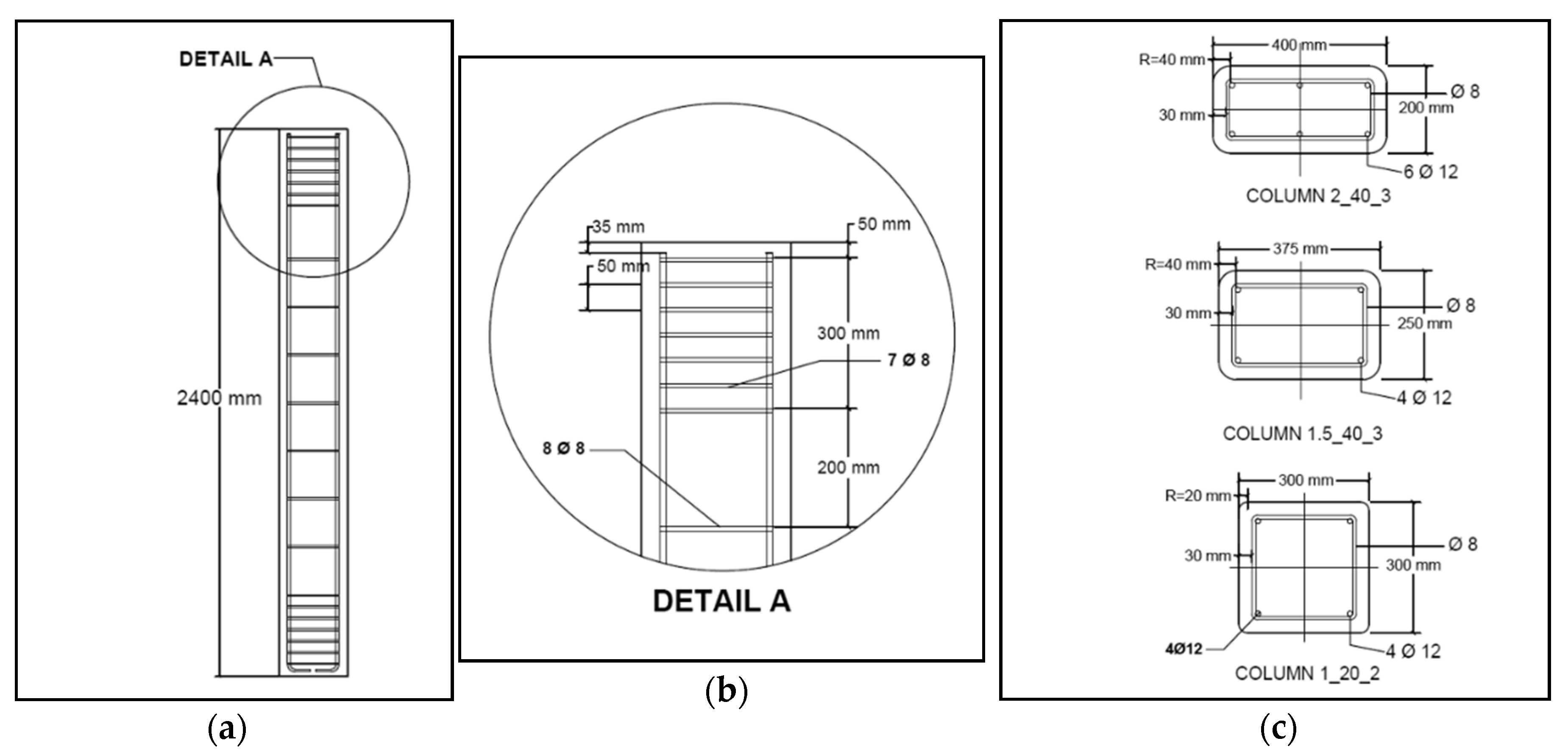
2.1. Main Parameters of Experimental Program

One of the main aims of the study is to research the effectiveness of FRP confinement in relation to the shape of the cross section, specially for square and rectangular sections with rounded corners. The experimental program includes centred compression tests performed on large-scale concrete prismatic specimens trying to approach real size building RC columns. The length of the full-scale specimens is 2400 mm.
The main variables of the experimental program are as follows:
  • The side-aspect ratio of the cross section or ratio to the sides of the concrete section (b/d). Specimens with a square section (b/d = 1) and a rectangular one (b/d = 1.5 and b/d = 2) were tested. Specifically, three sections were used: 300 × 300 mm2 (square section), 250 × 375 mm2 (rectangular, b/d = 1.5), and 200 × 400 mm2 (rectangular, b/d = 2).
  • The radius of curvature of the corners (Rc). The corners of the rectangular columns must be rounded before applying strengthening to avoid premature failure of the FRP jacket. For this study, two radii of curvature were used: 20 and 40 mm.
  • The amount of FRP reinforcement. Specimens were strengthened with 2 or 3 layers of CFRP (polymer reinforced with carbon fibres). The material has a nominal fibre thickness of 0.129 mm and its properties are described in Section 2.3 of this paper.
According to these parameters, the specimens were named as follows: first the cross section side-aspect ratio (b/d) is indicated, followed by the radius of curvature of the corners (Rc) in mm, and finally the number of layers of the CFRP strengthening.
In this paper, the results of four large-scale tests are presented. Three of them were externally strengthened with CFRP (carbon fibre reinforced polymers) and one tested without reinforcement as a reference. Table 1 shows the main parameters of these four specimens.

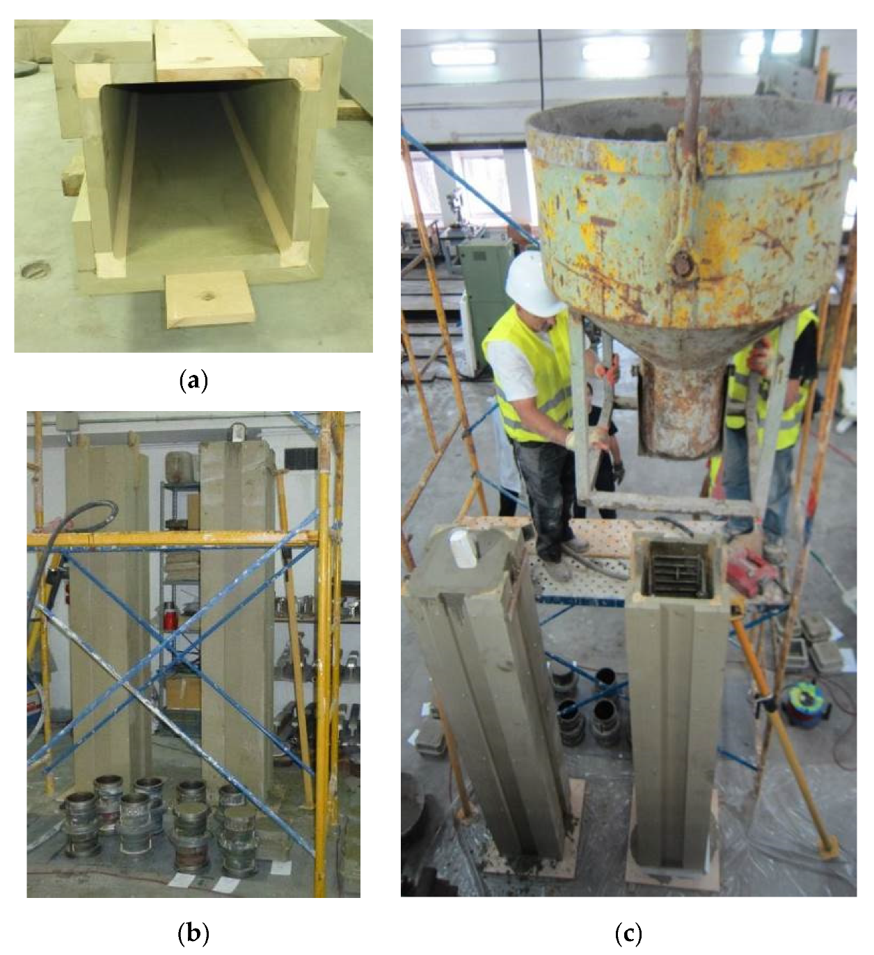
2.2. Specimen Preparation

The specimens were designed with minimum internal steel reinforcement in order to reproduce the situation of RC columns in old buildings, generally with little reinforcement and low compression strength concrete.
Figure 1 shows the reinforcement layouts of the prototypes. The longitudinal reinforcement was made of 12 mm diameter bars (four or six depending on the dimensions of the specimen cross section). The transverse reinforcement was made of 8 mm diameter stirrups spaced at 200 mm, except at the upper and lower ends of the column where they were arranged at 50 mm to avoid failure in these areas. The material of the reinforcement was B 500 S steel (steel yield stress of 500 N/mm2).
The concrete prismatic specimens were formed with a length of 2400 mm and the three different types of section indicated above. To obtain the planned radius of curvature of the corners (Rc), wooden formworks with rounded corners were used.
After the hardening of the concrete specimens, the corners were viewed and the irregular areas were repaired with mortar to ensure the intended radius of curvature. Figure 2 shows the wooden formwork and the cast of the specimens, which is done vertically.
The value of the concrete compressive strength (fco) was obtained by testing cylindrical normalized specimens (150 mm diameter and 300 mm height) at 28 days after casting. The concrete compressive strength (fco) of the 4 tested columns was low (between 15.8 N/mm2 and 20.1 N/mm2).
It should be noted that the use of concrete with low strength was common in older structures and it can often be found in rehabilitation works.

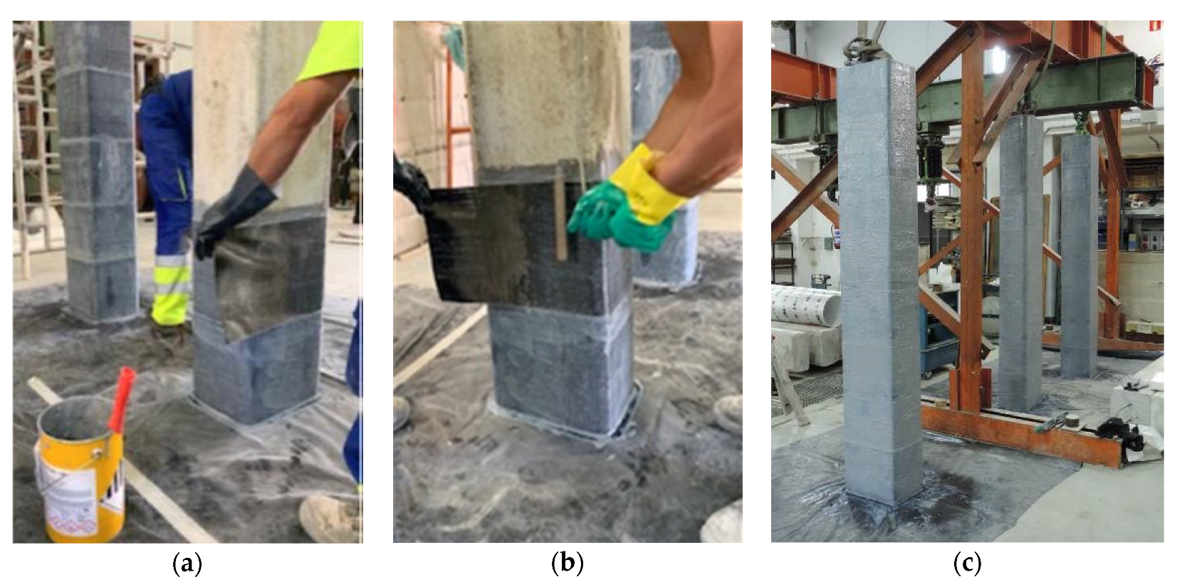
2.3. FRP Strengthening

The FRP material used for the strengthening is formed by unidirectional carbon fibre sheets with epoxy resin. The net fibre thickness is 0.129 mm for each reinforcement layer. Tensile testing of FRP flat coupons was carried out according to ISO 527-4 1997 [32]. A mean value of tensile strength of 4161 N/mm2 was obtained and a modulus of elasticity equal to 23.6918 N/mm2 (both properties refer to the net section of fibre). The mean value of the ultimate strain was equal to 0.017.
The FRP was applied by the hand lay-up technique or wrapping (Figure 3) which is the most common strengthening method.
This method consists of applying the unidirectional carbon fibre fabric and the resin to the specimen, forming the composite material on the concrete substrate when the resin is cured. All the fibres were oriented in a direction perpendicular to the axis of the pillar with a minimum overlap length of 200 mm. There was no FRP overlapping in the axial direction.
The specimens were reinforced along their full length with different numbers of layers of fibre, according to the test plan. Also, in order to avoid local failures in the heads, additional sheets formed by two layers of fibres were applied at the top and the bottom of the column (along a length of 300 mm). With this strengthening scheme, any failure is bound to happen at the central zone.

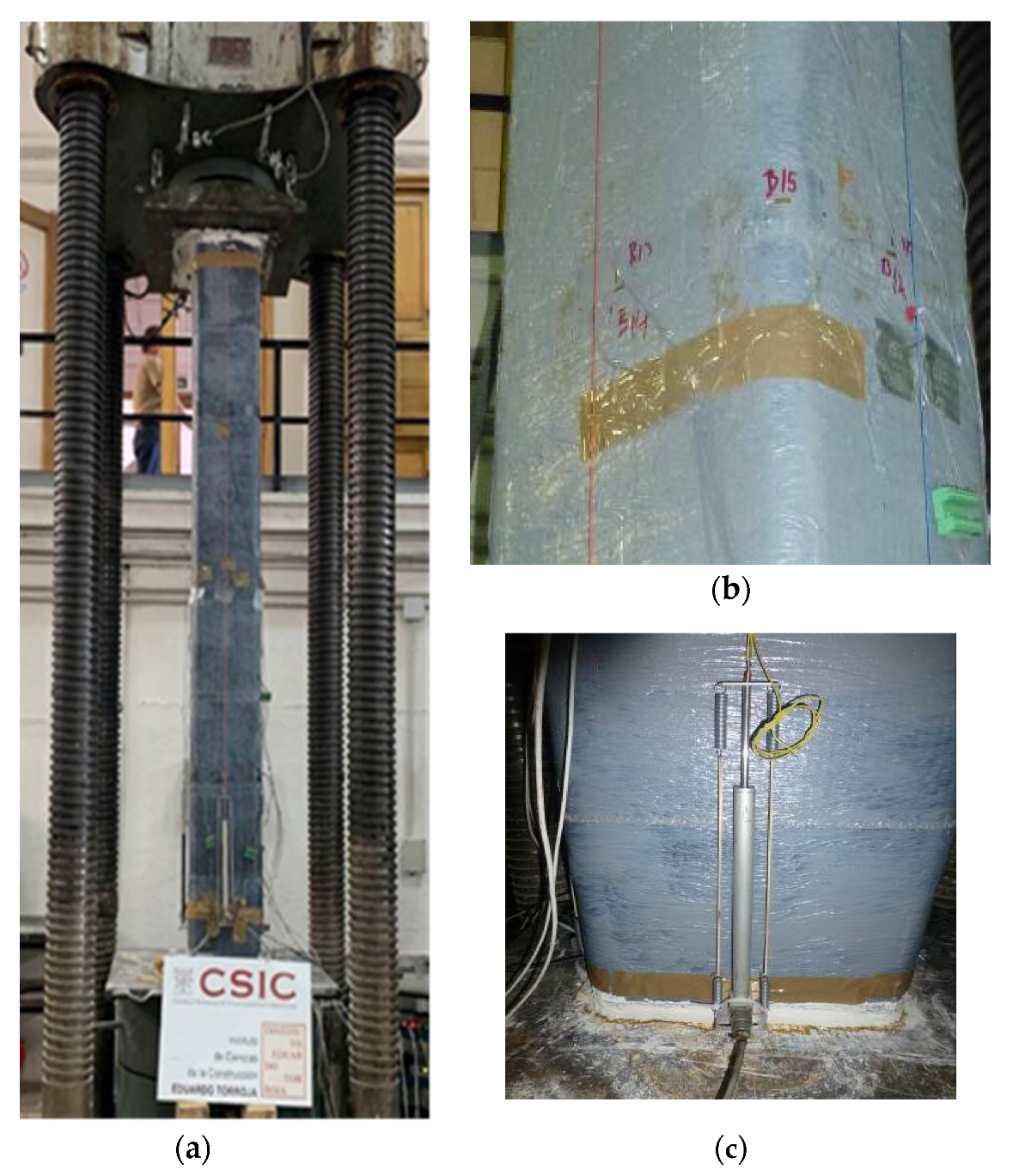
2.4. Test Set-Up and Instrumentation

The specimens were instrumented in order to know their stress–strain behaviour.
It is known that in rectangular sections the confining pressure exerted by the FRP jacket is not distributed evenly over the entire section but tends to be concentrated on the corners. For this reason, eight electrical strain gauges were glued onto the FRP jacket in transversal direction at half the height of the specimen: one strain gauge at the centre of each side and one at the central point of each rounded corner. The electrical strain gauges used were type BFLA-5-5 of TML 5 mm long.
The longitudinal strain was measured by four displacement sensors (Model LP803-10 with 250 mm range, Omega brand) which were placed on each column side, Figure 4. The shortening recorded by each sensor divided by the measured length (around 2300 mm) gave the longitudinal strain in the centre of each column face.
In addition, four electrical strain gauges were placed at mid-height of the column in the axial direction (one strain gauge at the centre of each side). These gauges were used to verify the displacement sensors readings.
The specimens were tested with compression load by means of a hydraulic actuator (class 2, UNE EN 7500-1), Icon 10.000 kN capacity.
The columns were carefully plumb and centred with respect to the load application device in order to carry out centred compression tests.
During the test, the applied load was increased with an initial speed of 2 kN/s until reaching 75% of the ultimate load of the reference prototype (column without FRP jacket). From this load, around 1200 kN, the test speed was half of the previous one, 1 kN/s until failure.

3. Experimental Results

The experimental results of the four specimen tests are summarized in Table 2, indicating for each one the following:
  • The unconfined concrete compressive strength (fco) obtained by testing of cylindrical standard samples.
  • The peak axial load (Qmax) or maximum load applied in the test.
  • The confined concrete strength (fcc) or concrete axial stress at peak load. This value is computed as the difference between the peak load (Qmax) and the load carried by the longitudinal steel reinforcement, divided by the net area of concrete. The load carried by longitudinal steel bars is given as its total area multiplied by the steel yield stress.
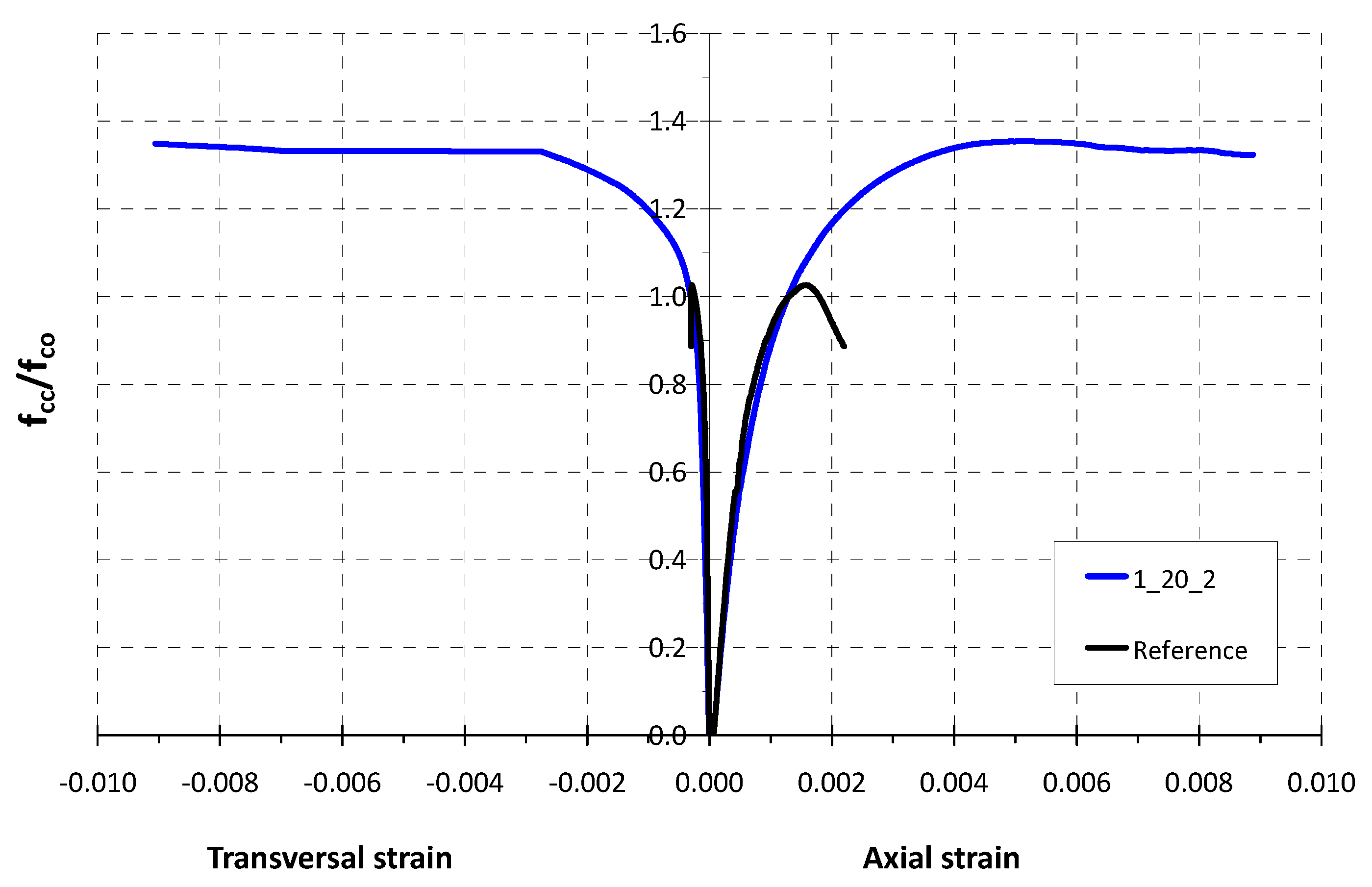
  • The rate of confined and unconfined concrete strength (fcc/fco) or strength enhancement ratio. It must be noted that the contribution of existing steel stirrups was neglected in this preliminary analysis.
  • The ultimate axial strain (εcc). The axial strains are obtained as the average of measurements from the displacement sensors.
  • The ultimate transversal strain, also called FRP effective strain (εf,eff). The transversal deformations are obtained as the average of measurements from the four side transversal measurements.
  • The relationship between the FRP effective strain (εf,eff) and the ultimate strain of the fibre obtained by standard tensile tests of flat coupons (εf). This rate (εf,efff) is commonly called the strain efficiency factor.
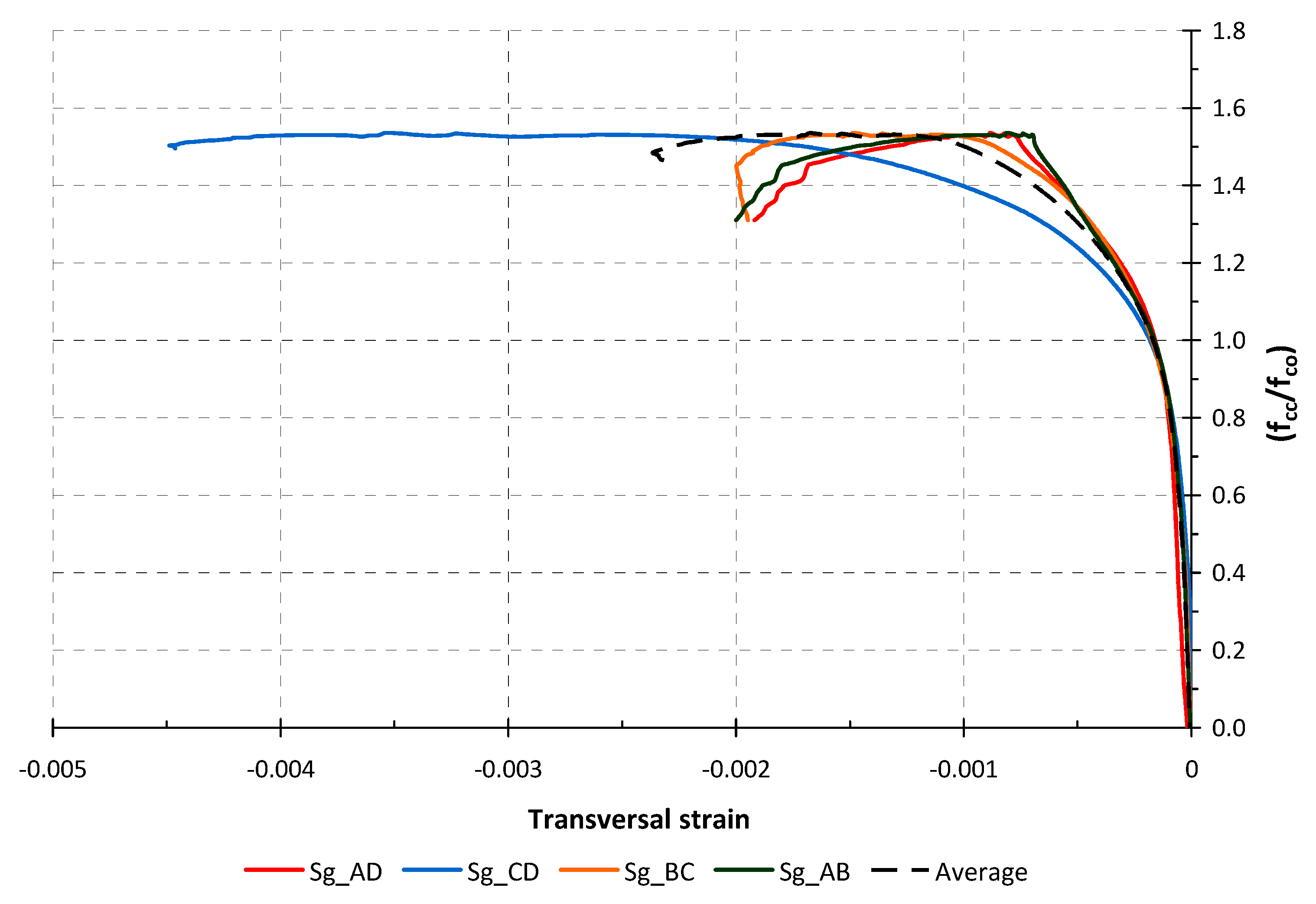
  • The maximum transversal strain (εfmax) measured by any of the transversal strain gauges located at the centre of the four faces.
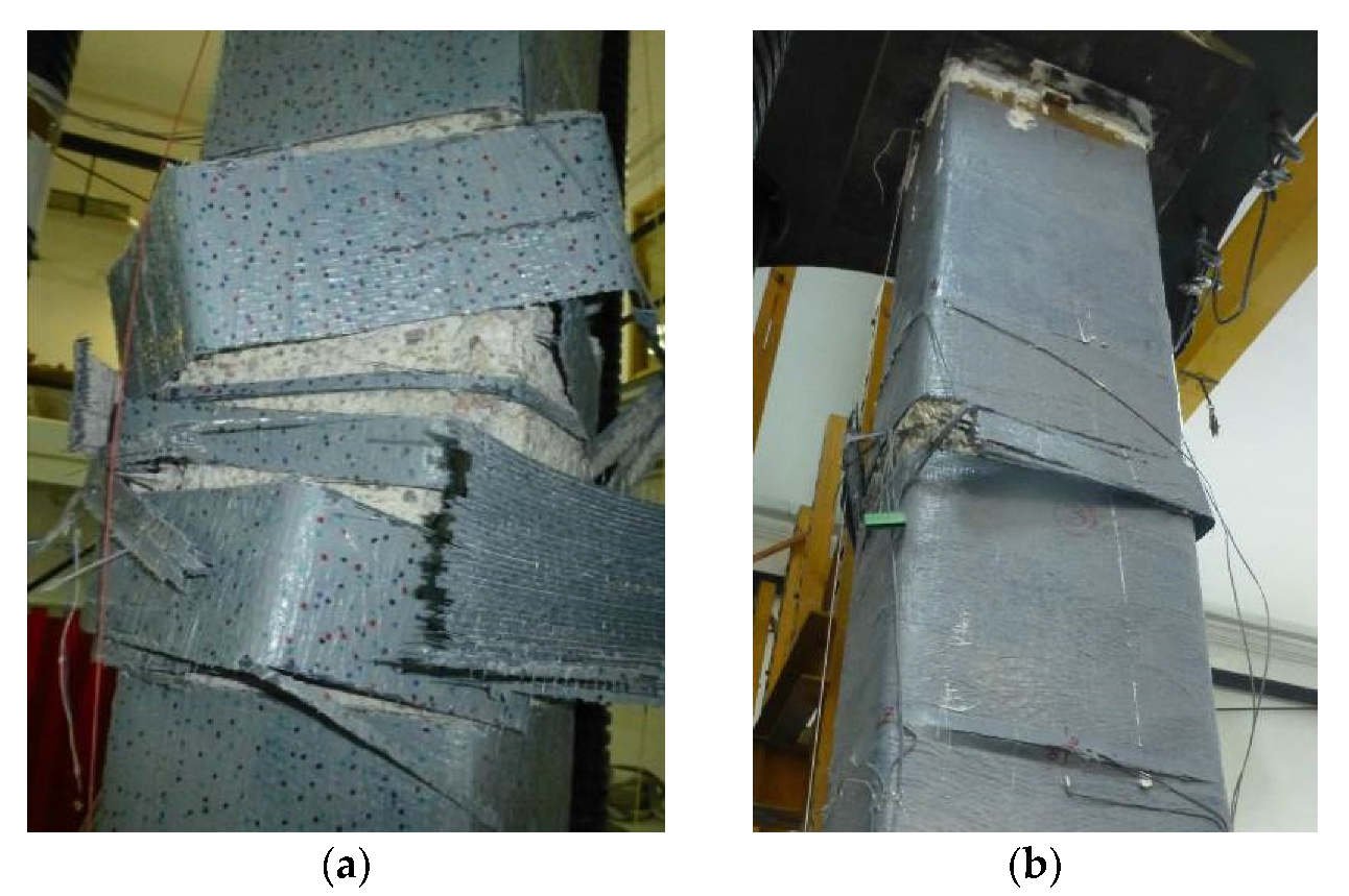
3.1. Failure Modes

The failure of the reference specimen (tested without FRP strengthening) was the typical one for RC columns, with vertical cracks and splitting of the concrete cover in the central area.
The main cause of failure of the FRP confined specimens was jacket rupture, usually next to a corner (Figure 5). Generally, no damage was observed in the specimen up to a load level close to failure. At the end of the test, some horizontal wrinkles began to be visible along the jacket, probably due to the significant axial shortening suffered by the column. Moments before the failure, some small noises could be heard, presumably because of the rupture of some FRP fibres. This was followed by an explosive failure, occurring with rupture of the FRP jacket in the central area where the internal concrete was completely disintegrated.

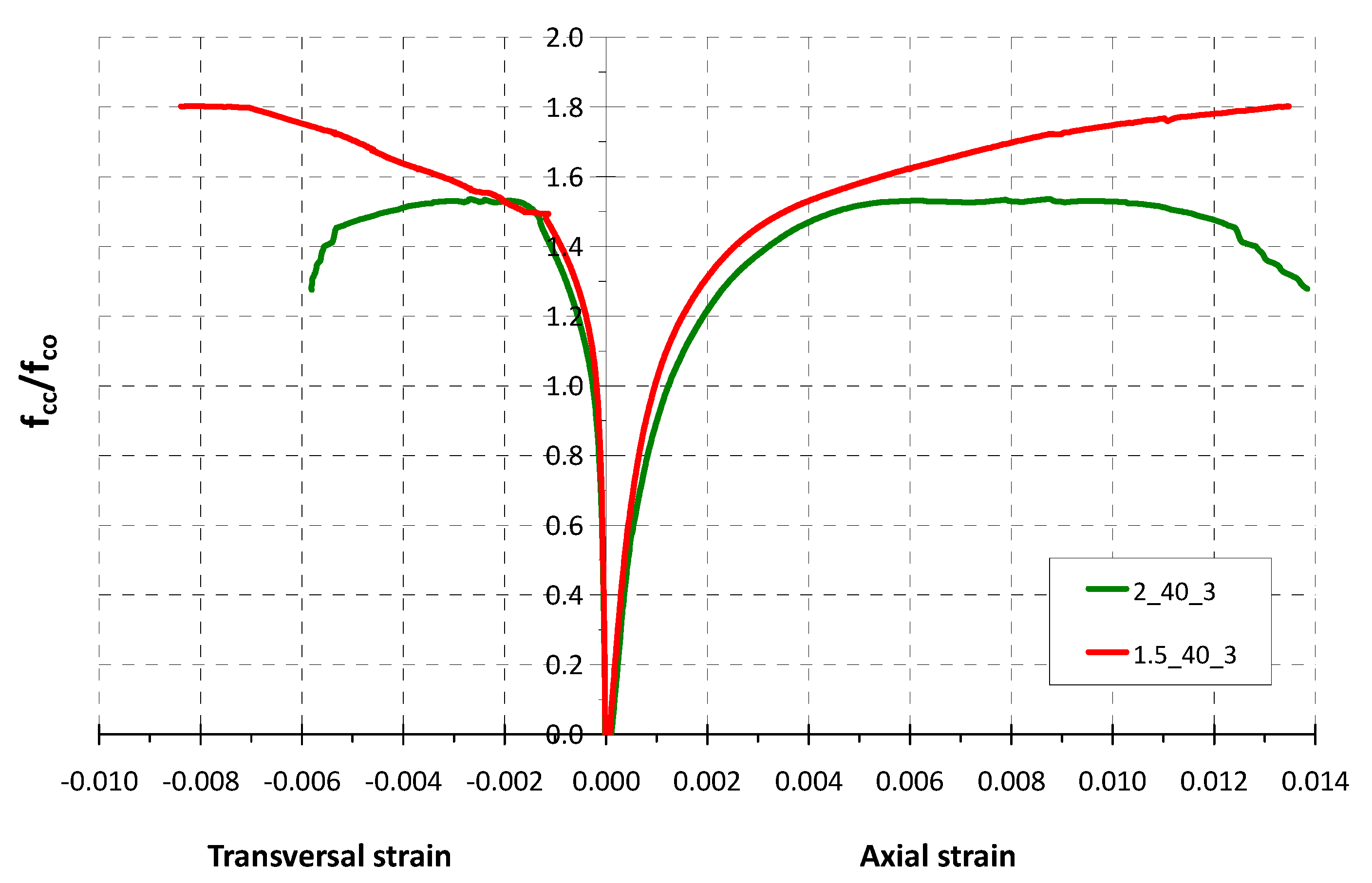
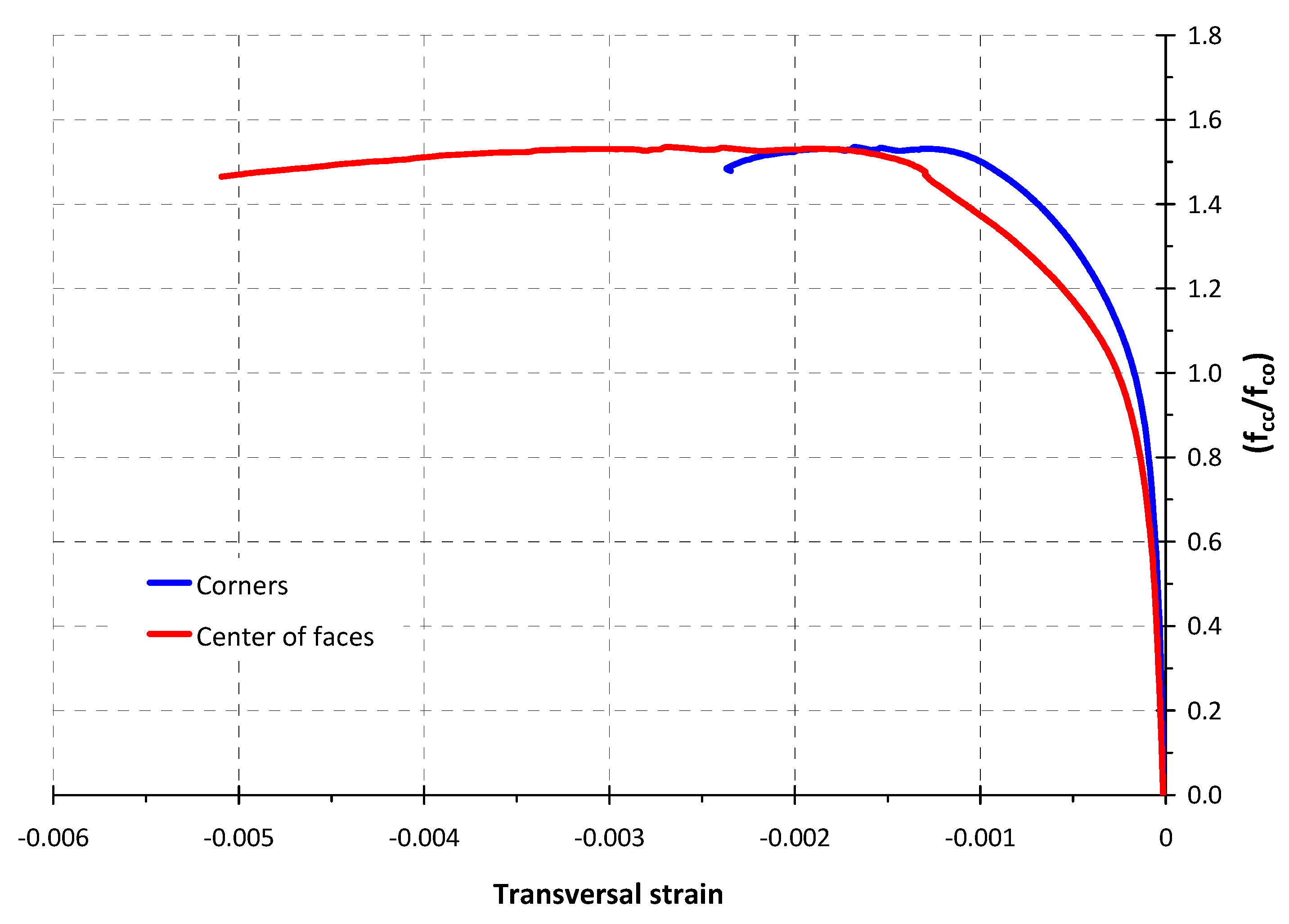
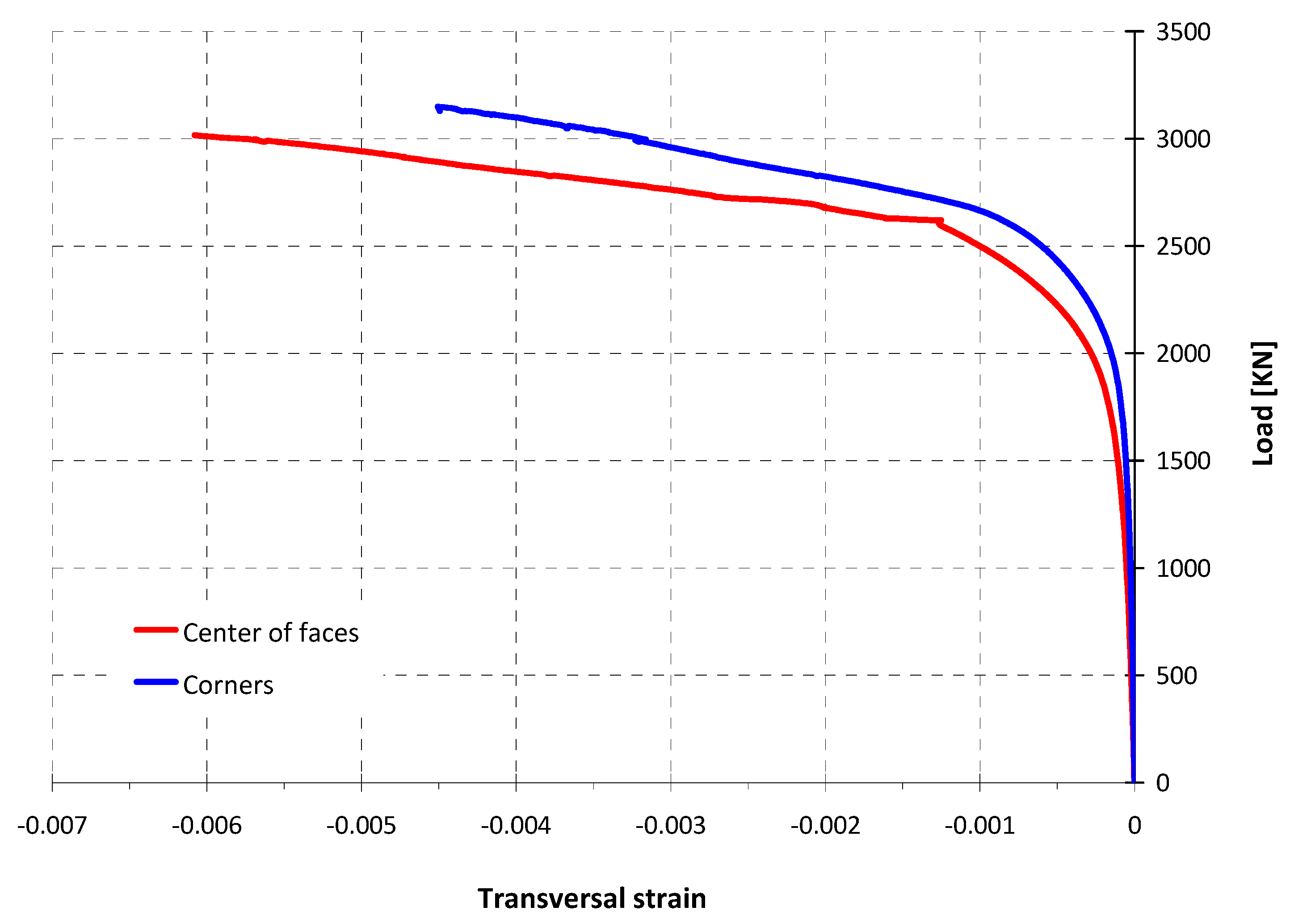
3.2. Strain-Stress Behaviour

The strain–stress curves of the tests are drawn in Figure 6 and Figure 7. In the X-axis of the graphics, the axial strains are represented as positive values and the transversal strains as negative ones in order to represent both curves simultaneously. The rate of confined and unconfined concrete strength (fcc/fco), or strength enhancement ratio, is plotted on the Y-axis.
Figure 6 shows the stress–strain behaviour of the two square section specimens, the reference one (unreinforced) and one column reinforced with two CFRP layers (specimen 1_20_2).
As can be observed, there is a first stage of the curves in which the behaviour of both columns is similar. This is due to the transversal strain being very small for low loads while the FRP wrapping exerts a very limited confinement pressure at the beginning of the test. When unconfined concrete strength is achieved, the concrete starts to crack and the transversal strain increases, thus the FRP confinement action is activated by restricting the lateral expansion of the concrete.
The peak load of the reference specimen test was reached when the axial concrete strain was around 0.0016 (0.16%) and the ultimate concrete strain was 0.0022 (0.22%). The maximum value of the normalized axial concrete stress (fc/fco) for this reference column was around 1.
On the other hand, in the test of the specimen 1_20_2, the peak load was reached when the axial strain was around 0.005 (0.5%) and the ultimate concrete strain was 0.0089 (around 0.9%). This means an enhancement of strain capacity of three and four times, respectively, regarding the reference column. As can be seen in Figure 6, once the maximum load is reached, it remains practically constant until failure. The ultimate load is slightly lower than the peak load.
In this specimen 1_20_2, the CFRP reinforcement increases the concrete strength up to 26.9 N/mm2 from an unconfined concrete strength (fco) near to 20 N/mm2, resulting in a strength enhancement ratio (fcc /fco) equal to 1.35 (strength capacity improvement of 35%).
The ultimate transversal strain value or FRP effective strain (εf,eff) is 0.9%. This value is considerably lower than the ultimate strain of the FRP material obtained in flat coupon tensile tests (1.7%). The ratio of these two strain values, often called the strain efficiency factor, would be 0.53.
Figure 7 shows the stress–strain behaviour of two FRP confined columns with rectangular cross-section and a side-aspect ratio (b/d) equal to 1.5 and 2. Both specimens have rounded corners with a radius of 40 mm and have been reinforced with three carbon FRP layers.
The ascending second branch of the stress–strain curve of specimen 1.5_40_3 is typical for well confined FRP concrete elements. For this specimen, the maximum load was reached at the end of the test. The confined concrete strength of the specimen (fcc) reached a value of 31.4 N/mm2 from an unconfined concrete strength (fco) equal to 17.4 N/mm2, resulting in a strength enhancement ratio (fcc/fco) equal to 1.80 (strength capacity improvement of 80%). The ultimate axial concrete strain was 0.0135 (1.35%).
In the test of the specimen 2_40_3, the second branch of the stress–strain curve is almost horizontal, although the applied load drops at the end of the test. The ultimate axial concrete strain was 0.0138 (1.38%).
In this specimen 2_40_3, the CFRP reinforcement increases the concrete strength up to 30.8 N/mm2 from an unconfined concrete strength (fco) near to 20 N/mm2, resulting in a strength enhancement ratio (fcc/fco) of 1.54. This strength capacity improvement of 54% is lower than the specimen 1.5_40_3 (80%) but can be considered significant.
As expected, less effectiveness of confinement is observed as the side-aspect ratio (b/d) increases. For the specimen 1.5_40_3 the strength enhancement ratio is greater, and the typical stress–strain behaviour with ascending second branch is observed. The FRP ultimate transversal strain is also lower than the ultimate strain of the FRP material obtained by standard tensile tests of flat coupons, with a strain efficiency factor equal to 0.49 for the specimen 1.5_40_3 and 0.34 for the column 2_40_3.
It should be noted that the ultimate axial strain (εcc) of both FRP confined rectangular specimens increases noticeably, reaching values near to 1.4%.
However, high values of concrete axial strains should be avoided, because, even if the FRP jacket is far from failure, the internal concrete will be very cracked and the column would not be able to withstand transversal forces. Some design guides (ACI, TR55) recommend considering a maximum value of the ultimate concrete strain of 0.01. For practical applications, the incidence of the strain capacity of the FRP-confined RC pillar on adjacent structural elements should be evaluated.

3.3. FRP Jacket Strains Obtained by Testing

For the study of the phenomenon of confinement by the FRP jacket, it is of special interest to know, in addition to axial deformations, the distribution of the transversal strains in the central section of rectangular columns. For this reason, eight electrical gauges were arranged in the cross section at the middle of the specimen. The strain gauges were named as “Sg” followed by a letter (A to D) that indicated the face where they were placed. The gauges glued on the corners were named using two letters, one from each side of the corner.
For centred compression tests, the readings of the axial deformations on the different faces must be similar. Figure 8 shows the axial strain to strength enhancement ratio (fcc/fco) in the specimen 2_40_3, representing the deformations obtained from each of the displacement sensors and the average trend. Figure 9 plots the strains of the same specimen from the four electrical gauges placed transversally on the middle of the face and its average trend. The faces B and D are the longer sides of this specimen 2_40_3.
The readings of the transversal gauges located on the corners of the mid-height cross section of Specimen 2_40_3, are also given in Figure 10. As can be seen in Figure 11, the average of the strain readings of the gauges installed on the corners are slightly smaller than the average of the strains at the middle of the side face. The same situation occurs in the test of specimen 1.5_40_3, as shown in Figure 12. This fact has been documented by other authors [20,22]. It could be caused by tensile strain due to confinement effect or a flexural strain due to the non-uniform concrete dilation inducing a lateral pressure on the jacket. The fact that the FRP jacket failure usually occurs next to corners is probably due to the high FRP strains of this area as well as the geometrical discontinuity of the concrete support on the corners.
The values of the FRP hoop rupture strain, or effective ultimate strain (εf,eff), estimated from tests are included in Table 2. These values are the mean of the readings of the transversal gauges located in the middle of each face, which resulted in being slightly higher than those glued on the corners. As can be seen in Table 2, the strain efficiency factor (εf,efff) of the columns tested decreases with increasing side-aspect ratio ranging from 0.34 for b/d = 2 to 0.53 for b/d = 1.
However, it must be noted that higher values than the effective ultimate strain (εf,eff) were registered during the tests. The value of the maximum transversal strain (εf,max) registered by any strain gauge located in the centre of the faces is also given in Table 2. In the tests of the columns 1_20_2 and 1.5_40_3, the maxima of the transversal strains (εf,max) were 0.01681 and 0.01642, these values are close to the deformation from tensile coupon tests (0.017).

4. Comparison of Experimental Results with Recommendations of the Design Guides

The experimental results of the confined concrete strength (fcc) of the columns were compared to the values obtained through the design recommendations proposed in ACI-440.2R-17 (2017), Concrete Society TR55 (2012) and CNR-DT 200 R1/2013 (2013). In order to know which formulation best fits the experimental results, in this study no safety factors for materials were used.
Table 3 shows the formulations of the guidelines considered.
The first column of Table 3 indicates the acronym of each guide and the second column shows the mathematical expressions to obtain the theoretical compressive strength of the confined concrete (f’cc).
The recommendations of the ACI and Concrete Society guidelines propose, for confined concrete, the stress-deformation model developed by Lam and Teng [16].
The ACI guide considers a value of 0.55 for the strain efficiency factor (kε) and the confinement ratio (fl/f’c) has to be at least 0.08 according to the research by Lam and Teng et al. [16]. This is the minimum level of confinement required to ensure a second non-declining branch in the stress–strain model. The model includes two reducing factors, ka and kb, which depend on two parameters: the cross-sectional area of the effectively confined concrete (Ae) and the ratio of sides (h/b).
On the other hand, the Concrete Society guide, although adopting the Lam and Teng stress–strain model, proposes one different expression in order to calculate the strength of confined concrete. This guide uses two factors related to the confined behaviour: the confinement ultimate strain capacity (ρε) and the confinement stiffness (ρk). Regarding the deformation efficiency factor (kε) proposes values between 0.25 and 0.4 depending on the geometry of the cross section.
Meanwhile the guide published in Italy CNR-DT 200 R1/2013 proposes calculation formulae agreed upon by a technical committee whose model describes a bilinear strain behaviour like the one proposed by Lam and Teng.
To obtain the theoretical capacity of the columns, the value of FRP strain efficiency factor is calculated following the formulation and indication of each guide. The results are shown in Table 4.
In the case of the square column 1_20_2 it was observed that the theoretical concrete confined strength (fcc) obtained from these guides is similar to the experimental results. However, for rectangular sections, it was observed that the experimental confined strength was significantly higher than the predicted value by using ACI and CNR-DT recommendations, and there were differences between the predicted values by the different guidelines. The approach by the Concrete Society TR55 2012 better fits the experimental results.
Regulations appear to be conservative with respect to an aspect ratio of the concrete section (b/d) greater than 1.5. However, it is to be noted that in the test of the column 2_40_3 the confined concrete strength (fcc) yielded a value 53% greater than the initial strength (fco). Regarding this observation, it should be considered that the columns of this experimental study were cast with low strength concrete (around 20 MPa), and confinement efficiency strongly depends on the unconfined concrete strength.
The predictions of the ultimate stress obtained using the TR55 guide fit better the experimental results. The reason for this, in the absence of further verification, may be that the TR55 model includes separately the FRP jacket ultimate strain and the effect of confinement stiffness, while the ACI and CNR formulations are more simplified, based solely on the confinement ratio. Further research is needed in order to obtain a shape factor and an accurate estimation of the FRP effective strain for rectangular columns.
Regarding the stress–strain curves, the different design guides have adopted simple models. These consist of a first parabolic part (phase of behaviour similar to unconfined concrete) and a second linear one (contribution of the FRP jacket). The suitability of this second branch depends on whether the theoretical prediction of the ultimate stress and strain values are adequate. The weakest point is the prediction of the ultimate concrete strain, an issue in which the dispersion observed in the experimental results of the literature is extremely wide.

5. Conclusions

In this paper, the results of axial compression tests of FRP wrapping RC columns were presented. The tests shown were four large-scale RC columns of non-circular section (three with CFRP jacket and one control column without external reinforcement). The specimens were made of concrete with low compression strength, common in older structures that can often be found in rehabilitation works.
The results obtained allow the following conclusions to be drawn:
  • In the case of low strength concrete, the FRP confinement can significantly improve not only the strain capacity but also the strength of rectangular section RC columns with rounded corners. A strength improvement of 80% was obtained for a rectangular section specimen with a side-aspect rate (b/d) of 1.5 and 54% for a column with a side-aspect rate (b/d) of 2, both were reinforced with three layers of CFRP.
  • The ultimate axial strain of concrete increased noticeably due to FRP confinement action, reaching values between 0.009 (0.9%) and 0.014 (1.4%) in the performed tests. For practical applications, high values of axial strains must be avoided. In this sense, some design guides (ACI, TR55) limit the ultimate concrete strain to 0.01.
  • The failure usually occurs suddenly and explosively by tensile rupture of the jacket fibres to a strain value much lower than that obtained by tensile testing of FRP coupons.
  • The strain efficiency factor (εf,efff) is a key parameter for the calculation of FRP wrappings. The values obtained in the tests presented are lower than those usually recommended by the design guides (around 0.55–0.60). The strain efficiency factors (εf, efff) from the tests were between 0.34 and 0.53 with an average value of 0.44.
  • The results obtained so far in this experimental program show that the strain efficiency factor (εf,efff) decreases with increasing cross section side-aspect ratio (b/d) although more tests are needed to support this finding.
  • The predictions of the theoretical capacity of the FRP-confined columns using the formulation of three existing codes (without applying the safety factors for materials) show that these regulations appear to be conservative for low-strength concrete columns with a side-aspect ratio of the concrete section (b/d) greater than 1.5.
  • The predictions obtained using the TR55 guide fit better the experimental results. The approach by the Concrete Society TR55 2012, whose formulation includes separately the FRP jacket ultimate strain and the effect of confinement stiffness, seems to be a valuable contribution, but further research is needed.
The above conclusions should be considered within the scope of the studied parameters, and with the limitations derived from the small number of tests carried out so far. The presented work is part of a more extensive test program.

Author Contributions

Data curation: A.d.D., V.J.C.; Formal analysis: S.M., A.d.D., V.J.C., J.P.G.; Conceptualization, Supervision: J.P.G.; Investigation: F.J.B., G.R., R.P.S.; Methodology: S.M., A.d.D., V.J.C., L.E. and J.P.G.; Writing—original draft and writing—review and editing: S.M., A.d.D., V.J.C., L.E. All authors have read and agreed to the published version of the manuscript.

Funding

This work was supported by research project BIA2016-80310-P, funded by AEI (Research State Agency of the Spanish Ministry of Science and Innovation) and the FEDER (European Regional Development Fund).

Acknowledgments

The authors acknowledge BETAZUL S.A. and SIKA S.A.U. for performing the strengthening work and providing FRP materials. V. J. Castro acknowledges the financial support (FPI grant BES2017-080647) of the Spanish MICINN and the European Social Fund.

Conflicts of Interest

The authors declare no conflict of interest. The funders had no role in the design of the study; in the collection, analyses, or interpretation of data; in the writing of the manuscript, or in the decision to publish the results.

References

  1. Lam, L.; Teng, J.G. Behaviour and modelling of fiber reinforced polymer-confined concrete. J. Struct. Eng. 2004, 130, 1713–1723. [Google Scholar]
  2. Ozbakkaloglu, T.; Lim, J.C.; Vincent, T. FRP-confined concrete in circular sections: Review and assessment of stress–strain models. Eng. Struct. 2013, 49, 1068–1088. [Google Scholar] [CrossRef]
  3. Mirmiran, A.; Shahawy, M.; Samaan, M.; El Echary, H.; Mastrapa, J.C.; Pico, O. Effect of Column Parameters on FRP-Confined Concrete. J. Compos. Constr. 1998, 2, 175–185. [Google Scholar] [CrossRef]
  4. Pessiki, S.; Harries, K.A.; Kestner, J.; Sause, R.; Ricles, J.M. The axial behaviour of concrete confined with fiber reinforced composite jackets. J. Compos. Constr. 2001, 5, 237–245. [Google Scholar] [CrossRef]
  5. Moran, D.A.; Pantelides, C.P. Stress-Strain Model for Fiber-Reinforced Polymer-Confined Concrete. J. Compos. Constr. 2002, 6, 233–240. [Google Scholar] [CrossRef]
  6. Wang, L.-M.; Wu, Y.-F. Effect of corner radius on the performance of CFRP-confined square concrete columns: Test. Eng. Struct. 2008, 30, 493–505. [Google Scholar] [CrossRef]
  7. Wu, Y.-F.; Wei, Y.-Y. Effect of cross-sectional aspect ratio on the strength of CFRP-confined rectangular concrete columns. Eng. Struct. 2010, 32, 32–45. [Google Scholar] [CrossRef]
  8. Vincent, T.; Ozbakkaloglu, T. Influence of fiber orientation and specimen end condition on axial compressive behaviour of FRP-confined concrete. Constr. Build. Mater. 2013, 47, 814–826. [Google Scholar] [CrossRef]
  9. Wu, Y.-F.; Jiang, J.-F. Effective strain of FRP for confined circular concrete columns. Compos. Struct. 2013, 95, 479–491. [Google Scholar] [CrossRef]
  10. Eid, R.; Paultre, P. Compressive behavior of FRP-confined reinforced concrete columns. Eng. Struct. 2017, 132, 518–530. [Google Scholar] [CrossRef]
  11. De Luca, A.; Nardone, F.; Matta, F.; Nanni, A.; Lignola, G.P.; Prota, A. Structural Evaluation of Full-Scale FRP-Confined Reinforced Concrete Columns. J. Compos. Constr. 2011, 15, 112–123. [Google Scholar] [CrossRef]
  12. Lam, L.; Teng, J. Design-oriented stress–strain model for FRP-confined concrete. Constr. Build. Mater. 2003, 17, 471–489. [Google Scholar] [CrossRef]
  13. Nisticò, N.; Monti, G. RC square sections confined by FRP: Analytical prediction of peak strength. Compos. Part. B Eng. 2013, 45, 127–137. [Google Scholar] [CrossRef]
  14. De Diego, A.; Arteaga, Á.; Fernández, J. Strengthening of square concrete columns with composite materials. Investigation on the FRP jacket ultimate strain. Compos. Part B Eng. 2019, 162, 454–460. [Google Scholar] [CrossRef]
  15. Chaallal, O.; Hassan, M.; Shahawy, M. Performance of axially loaded short columns strengthened with CFRP wrapping. J. Compos. Constr. ASCE 2003, 7, 200–208. [Google Scholar] [CrossRef]
  16. Lam, L.; Teng, J.G. Design-Oriented Stress-Strain Model for FRP-Confined Concrete in Rectangular Columns. J. Reinf. Plast. Compos. 2003, 22, 1149–1186. [Google Scholar] [CrossRef]
  17. Maalej, M.; Tanwongsval, S.; Paramasivam, P. Modelling of rectangular RC columns strengthened with FRP. Cem. Concr. Compos. 2003, 25, 263–276. [Google Scholar] [CrossRef]
  18. Rochette, P.; Labossière, P. Axial Testing of Rectangular Column Models Confined with Composites. J. Compos. Constr. 2000, 4, 129–136. [Google Scholar] [CrossRef]
  19. Wang, Y.C.; Restrepo, J.I. Investigation of concentrically loaded reinforced concrete columns confined with glass fiber-reinforced polymer jackets. ACI Struct. J. 2001, 98, 377–385. [Google Scholar]
  20. Rocca, S. Experimental and Analytical Evaluation of FRP-Confined Large Size Reinforced Concrete Columns. Ph.D. Thesis, University of Missouri-Rolla, Rolla, MO, USA, 2007. [Google Scholar]
  21. Toutanji, H.; Han, M.; Gilbert, J.; Matthys, S. Behavior of Large-Scale Rectangular Columns Confined with FRP Composites. J. Compos. Constr. 2010, 14, 62–71. [Google Scholar] [CrossRef]
  22. Zeng, J.; Lin, G.; Teng, J.; Li, L. Behavior of large-scale FRP-confined rectangular RC columns under axial compression. Eng. Struct. 2018, 174, 629–645. [Google Scholar] [CrossRef]
  23. Pham, T.M.; Hadi, M.N.S. Stress Prediction Model for FRP Confined Rectangular Concrete Columns with Rounded Corners. J. Compos. Constr. 2014, 18, 04013019. [Google Scholar] [CrossRef] [Green Version]
  24. Wu, Y.-F.; Wei, Y. General Stress-Strain Model for Steel- and FRP-Confined Concrete. J. Compos. Constr. 2015, 19, 04014069. [Google Scholar] [CrossRef]
  25. ACI Committee 440 440.2R-17. Guide for the Design and Construction of Externally Bonded FRP Systems for Strengthening Concrete Structures; American Concrete Institute (ACI): Farmington Hills, MI, USA, 2017. [Google Scholar]
  26. National Research Council, Advisory Committee on Technical Recommendations for Construction. Guide for the Design and Construction of Externally Bonded FRP Systems for Strengthening Existing Structures, CNR-DT200_R1; National Research Council (CNR): Rome, Italy, 2013. [Google Scholar]
  27. Concrete Society. Technical Report. Design Guidance for Strengthening Concrete Structures Using Fibre Composite Materials, 3rd ed.; TR55; Concrete Society: Camberley, UK, 2012. [Google Scholar]
  28. Triantafillou, T.; Matthys, S.; Audenaert, K.; Balázs, G.; Blaschko, M.; Blontrock, H.; Czaderski, C.; David, E.; Di Tomasso, A.; Duckett, W.; et al. Fib Bulletin 14. Externally Bonded FRP Reinforcement for RC Structures; 2001; Available online: https://www.fib-international.org/publications/fib-bulletins/externally-bonded-frp-reinforcement-for-rc-structures-100-detail.html (accessed on 9 July 2020).
  29. Wei, Y.-Y.; Wu, Y.-F. Unified stress–strain model of concrete for FRP-confined columns. Constr. Build. Mater. 2012, 26, 381–392. [Google Scholar] [CrossRef]
  30. Masia, M.J.; Gale, T.N.; Shrive, N.G. Size effects in axially loaded square-section concrete prisms strengthened using carbon fibre reinforced polymer wrapping. Can. J. Civ. Eng. 2004, 31, 1–13. [Google Scholar] [CrossRef]
  31. Martínez, S.; Gutiérrez, J.P.; de Diego, A.; Castro, V.J.; Echevarría, L.; Barroso, F.J.; López, C. Strengthening of low-strength concrete columns with fibre reinforced polymers. Full-scale tests. In Proceedings of the Rehabend 2020, 8th Euro-American Congress, Construction Pathology, Rehabilitation Technology and Heritage Management, Granada, Spain, 24–27 March 2020. [Google Scholar]
  32. ISO 527-4 1997. Plastics—Determination of Tensile Properties—Part 4: Test Conditions for Isotropic and Orthotropic Fibre-Reinforced Plastic Composites; British Standards Institution: London, UK, 1997. [Google Scholar]
Figure 1. Reinforcement detailing and cross-section dimensions: (a) Specimen elevation; (b) Detail A; (c) Reinforcement and dimensions of the different cross-sections.
Infrastructures 05 00091 g001
Figure 2. Cast process of the specimens: (a) Detail of a wooden formwork with rounded corners; (b) General view of two wooden formwork and cylindrical normalized specimens; (c) Cast process.
Infrastructures 05 00091 g002
Figure 3. Fibre reinforced polymer (FRP) strengthening process: (a) Fibre application by the hand lay-up technique; (b) Pressing with a roller in the direction of the fibres (c) General view of specimens after strengthening.
Infrastructures 05 00091 g003
Figure 4. Test set-up and instrumentation: (a) Test set-up; (b) Axial and transversal strain gauges placed at the centre of each side and the corners at the middle of the column; (c) Displacement sensor.
Infrastructures 05 00091 g004
Figure 5. Failure of specimens: (a,b) Failure due to rupture of FRP fibres near the corners.
Infrastructures 05 00091 g005
Figure 6. Stress–strain behaviour of two square section specimens (Reference and 1_20_2).
Infrastructures 05 00091 g006
Figure 7. Stress–strain behaviour of two rectangular section specimens strengthened with 3 CFRP layers (2_40_3 and 1.5_40_3).
Infrastructures 05 00091 g007
Figure 8. Axial strain to strength enhancement ratio in the specimen 2_40_3.
Infrastructures 05 00091 g008
Figure 9. Transversal strain to strength enhancement ratio in the specimen 2_40_3 (readings on the middle of the face).
Infrastructures 05 00091 g009
Figure 10. Transversal strain to strength enhancement ratio in the specimen 2_40_3 (readings on the corners).
Infrastructures 05 00091 g010
Figure 11. Comparative transversal strain measurements in specimen 2_40_3.
Infrastructures 05 00091 g011
Figure 12. Comparative transversal strain measurements in specimen 1.5_40_3.
Infrastructures 05 00091 g012
Table 1. Main parameters of specimens.
SpecimenSection (mm2)b/dRc (mm)Number of CFRP Layers
Reference300 × 3001--
1_20_2300 × 3001202
1.5_40_3250 × 3751.5403
2_40_3200 × 4002403
Table 2. Experimental results.
Specimenfco (N/mm2)Qmax (kN)fcc (N/mm2)fcc/fcoεccεf,effεf,efffεf,max
Reference15.861660.43--0.00220---
1_20_219.852623.3026.871.350.008890.009060.530.01681
1.5_40_317.443115.4331.431.800.013500.008380.490.01642
2_40_320.092743.8030.851.540.013860.005810.340.00628
Table 3. Mathematical expressions to obtain the confined concrete strength (fcc) by different design guides.
GuideCompressive Strength of Confined Concrete
ACI-440.2R (2017)f′cc = f′c + ψf 3.3 ka fl
CONCRETE SOCIETY TR55 (2012)(f′cc / f′c) = 1 + 5.25 (kε ρk − 0.01) ρε
CNR-DT 200 (2013)(f′cc / f′c) = 1 + 2.6 (fl,eff /f′c) 2/3
Table 4. Comparison of the experimental confined concrete strength (fcc) to predictions by using different design guides.
Specimenfco (N/mm2)fcc
(N/mm2) Experimental
fcc
(N/mm2) ACI-440.2R
fcc
(N/mm2) TR55
fcc
(N/mm2) CNR-DT 200
1_20_219.8526.8724.1925.6324.48
1.5_40_317.4431.4320.9329.0822.47
2_40_320.0930.8522.1532.7923.91
Publisher’s Note: MDPI stays neutral with regard to jurisdictional claims in published maps and institutional affiliations.

