Abstract
Recent seismic events that hit the central part of Italy have highlighted again the high vulnerability of the historical and architectonical heritage of Italy and the importance of preserving it. However, the seismic assessment of monumental buildings is particularly complex because each historical construction is a singular case realized by specific techniques. Therefore, the first step should be the knowledge of the building even if it is a difficult task. In the present paper, the seismic behavior of an important nineteenth century astronomical observatory, constructed between 1816 and 1819, was investigated. The building, located in Naples, in the southern part of Italy, and classified by the Italian code as an area of medium seismic hazard, was analyzed in the elastic and inelastic range under seismic actions. In this study, the results of two different models were proposed and critically compared. The first one was implemented by shell elements for walls and vaults developing a linear dynamic analysis, while the second one simulates the building through “equivalent frames” applying a nonlinear static analysis.
1. Introduction
Monumental buildings have an inestimable value for our world cultural heritage. For this reason, continuous efforts are devoted to understanding their structural behavior [1]. In recent decades, due to the extensive damage caused to the Italian monumental heritage during earthquakes [2], increasing attention has been devoted specifically to the issue of the seismic vulnerability of monuments.
The latter is a complex task due to various reasons: the use of a variety of locally available technologies and materials, the limited knowledge of the mechanical properties of the materials, the relatively high flexibility of the floor diaphragms, the highly nonlinear behavior of the masonry and the complexity of the geometrical configuration.
However, there are two main critical issues in the seismic assessment of complex historical structures: (i) the definition of the best modeling choice and (ii) the lack of a standardized procedure to perform the seismic analysis and verification.
Regarding the first point, different models based on different theoretical approaches are available such as micromodels and macromodels [3].
The peculiarity of micromodels is the simulation of masonry elements as composed by bricks and mortar joints separately, also with an interface behavior; therefore, they can be employed for walls or small constructions due the high computational effort. Instead, the model based on the “macromodeling” approach considers the masonry material as a homogeneous equivalent one [4,5]. In the literature, several macromodels based on homogenization techniques, describing the masonry at the structural level with an equivalent material whose properties are evaluated at the cell level, can be found [6,7]. However in the field of macromodeling different solutions, that are more or less sophisticated, are available to take in account the real complexity of masonry. The latter is more difficult for the historical structures realized using not standard and sometimes not well known techniques and materials.
It is worth to highlight that among the macromodels, the “equivalent frame” method is also commonly adopted [8,9,10] to carry out a global analysis of the building taking into account the different failure mechanisms that can occur. In particular, the in-plane failure of the masonry panels is due to shear or flexure; in the first case, diagonal compression or sliding can be attained while in flexure the rocking phenomenon can happen. According to this approach, the masonry structure is modeled as an assembly of vertical pier and horizontal spandrel that are monodimensional elements interconnected by fully rigid regions whose extension simulate the overlapping of the horizontal and vertical bidimensional elements [11].
The different approaches can be implemented in finite element modeling (FEM), which assures an efficient optimal computational tool for the analysis of deformable structures considering the linear and non-linear behavior in the static and dynamic field.
In fact, to perform the seismic analysis at the ultimate limit state of a masonry building through finite element method (FEM), both linear and nonlinear analysis in the static and dynamic field could be employed [12,13]. The choice of the type of analysis depends on the aim of the study (capacity in strength or ductility) and the characteristics of the building (irregular in plan or height, ductile materials). The macromodeling by FE can be developed adopting discrete solid or shell elements that allow to reproduce the shapes of irregular masonry walls and curved surfaces (as the vaults); alternatively, special monodimensional macroelements can be used for the walls assessing an equivalent frame. In this last case, irregular shapes of the panels or curved elements cannot be modeled but can be introduced like masses. The use of 3D or 2D elements allows to evaluate the local concentrations of stresses or damage, conversely the equivalent frame only gives information about the global failure of the macroelements. In both approaches, the global behavior of the construction can be determined.
For both the approaches by FEM, the linear and nonlinear behavior can be considered. The nonlinear behavior is introduced by the constitutive relationship of the material in 3D and 2D approaches or by lumped plasticity. It is clear that the linear analysis is more significant for the 3D and 2D elements that allow to understand the location of the maximum stress concentration while the equivalent frame identifies the more stressed element but not the local damage, therefore it is necessary to introduce the nonlinear behavior with plastic hinges to consider the local weakness.
Furthermore, the nonlinear behavior allows to use the post-elastic resources of materials, that is an important concept of the performance-based seismic design [14]. In this latter approach the design requires to compare the seismic demand with the building capacity, both expressed in terms of displacements, therefore a nonlinear analysis, at least a push-over analysis, that consists in applying a distribution of increasing lateral loads up to failure is necessary [15,16,17,18,19,20,21].
Both Italian and European Codes [22,23] suggest using nonlinear static analysis but they are generally oriented to ordinary buildings, instead recommendations addressed to monumental assets [24] only give general principles and indications for possible methodologies of analysis.
In addition, especially for masonry churches, basilica-churches or monumental buildings with an irregular shape, the dynamic response of the structure could further complicate the seismic analysis, since the first vibration modes are not able to accurately describe it as in the case of regular buildings. In fact, the first modes don’t significantly contribute to the seismic response of the structure in the case of a building with irregular plan layout or with parts connected only in few points. Therefore, conventional analysis methods characterized by higher contribution of the first modes, as the push-over analysis could be, are not suitable for this kind of monumental buildings as underlined by [25,26].
For other types of historical constructions, such as a bell tower incorporated in a church, fortified constructions, monumental palaces, frequently grown up over time by subsequent erections of structural units, the seismic behavior is ruled by the structural response of the interacting units as specified by [27].
Considering the complexity and uniqueness of the historical buildings together with the various modeling approaches, the aim of this paper was to critically compare and discuss two different model strategies. The first one was the use of shell elements for walls and vaults developing a linear dynamic analysis, while the second one is the adoption of the “equivalent frames” method applying a nonlinear static analysis.
The comparison is developed through the application to the wonderful example of a nineteenth century astronomical observatory, built between 1816 and 1819 on a hill of the city of Naples. This building has been selected for the study because it introduces several typical aspects of masonry historical buildings as irregular layouts, vaults, masonry made of natural stone, a heavy stone façade that contributes to the seismic masses, allowing comments that can be generalized.
2. The Case Study
2.1. Building Description
The “Astronomical Observatory of Capodimonte”, one of the twelve Italian observatories constituting the National Institute of Astro-Physics (INAF), the main Italian company for astronomical and astrophysical research from land and space, is located on top of the hill “Miradoris” in the city of Naples. The research started with the analysis of historic data. The construction works of the original structure were promoted by Gioacchino Murat in 1812 but the structure was inaugurated thanks to Ferdinando I of Borbone in 1819. In 1935, the original structure was extended with two rooms at the two extreme sides in the longitudinal direction. The new parts were designed to be integrated in the same style of the original building but they can be distinguished by the presence of a coating and a cornice in mortar and not in natural stone, as for the ancient construction. Figure 1a shows the general view of the building.
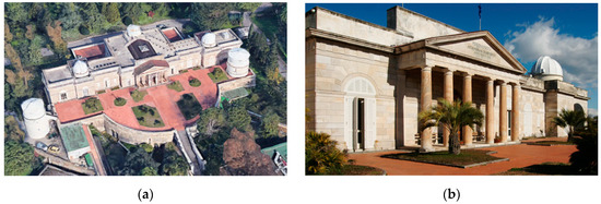
Figure 1.
(a) General overview; and (b) main entrance of the building
2.2. Geometrical and Material Data
As a preliminary step, the complexity of the building required to acquire a detailed knowledge of its geometry. Therefore, a complete in situ inspection was carried out for understanding the organization of the structure. The plan layout of the ground floor of the astronomical observatory is reported in Figure 2.
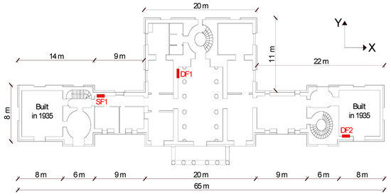
Figure 2.
Plan layout of the ground floor.
The building was realized using tuff masonry that is typical of Campania Region in the South of Italy where the building is located. It has an elongated rectangular shape and approximately its dimensions are 65 m × 20 m. It has two stories; both the underground floor and the ground floor are approximately 4.0 m high. The thickness of the walls varies between 1.00 and 1.55 m at the underground floor and 0.50 and 1.00 m at the ground floor. The peculiarity of this building is the presence of a heavy stone cladding whose thickness equal to 25 cm was measured by means of a hole. This aspect is particularly important and it will be considered in the following seismic analysis as it behaves as an additional mass.
The main entrance to the building is preceded by a pronaos surmounted by an architrave, the tympanum and other classical elements of the Greek temple architecture (see Figure 1b). In the building, it is possible to recognize three main blocks: a central square block and two rectangular lateral blocks. The main rectangular room (central atrium) is characterized by two lines of marble columns and it is covered by a barrel vault with a glass skylight. Additionally, the lateral zones adjacent to the central atrium were covered by barrel vaults or a hemispherical dome, except the last rooms at the two ends that were added in 1935 using the same stone for masonry while the floor was realized by iron beams and clay tiles.
Semi-destructive diagnostic tests ensuring a deeper level of knowledge of the structure were employed; in particular, three tests with flat jacks, whose position was been indicated in the figure with red marks, were carried out. A single flat jack test (SF1) was performed to ensure the determination of the actual compression stresses in the masonry walls, useful for validating the numerical model. The test was carried out by introducing a thin flat-jack into the mortar layer. A compression stress of approximately 0.25 MPa was obtained. Instead, two double flat jacks were performed to identify the mechanical characteristics, one (DF1) in the more ancient part of the building and one (DF2) at the extreme side rooms constructed in 1935 (see Figure 2). For the ancient part of the building, the Young modulus E and the Poisson ratio υ resulted equal to 905 MPa and 0.2 respectively whereas the volumetric weight ϒ was equal to 14 kN/m3 and the masonry average compressive strength fm was equal to 2 MPa. Instead, for the newer zones, the Young modulus E and the average compressive strength fm resulted equal to 450 and 1.5 MPa, respectively. It is worth noting that the values related to the old part of the building are in good agreement with the results from the laboratory tests on Neapolitan yellow tuff masonry [28] showing a mean compressive strength equal to 2.78 MP and an experimental Young’s modulus varying between 630 and 2943 MPa. Instead, the values related to the new part of the building are at least 50% lower than the previous ones. Finally, the results evidenced the higher quality of the material and hand-making of the more ancient part of the construction.
3. Finite Element Models
Two different models were considered. The first one was a linear model developed by software SAP2000 [29]. The geometry was based on the results of the in situ survey and the masonry walls were modeled using shell elements paying attention to reproduce their main geometric irregularities and all the openings of the building. The hypothesis of the thick-shell elements was considered for all the surface elements, defined using four nodes and six degrees of freedom for each node, corresponding to three translations, along the axes x, y and z, and three rotations of vectors, parallel to the same axes. Thickness between 0.50 m and 1.55 m were considered to simulate the structural elements. The mesh size was chosen to be approximately 50 cm in order to simulate well the real mass (inertial loads for dynamic analysis) distribution through the ideal concentration of masses at the nodes.
The columns of the central hall and the facade were modeled by beam elements. The connection between the soil and the structure was considered rigid.
For the simulation model, 17,679 nodes, 18,051 surface elements with an average dimension of 0.50 m and 36 beam elements were used.
The masses were directly associated with the structural elements according to the density and geometric dimensions; a uniform area mass was assigned to the floors according to their weight. To simulate the live load, a constant load of 0.5 kN/m2 was considered for the floor elements.
The elastic parameters like Young’s modulus E, Poisson’s coefficient ν, and weight per unit volume γ are reported in Table 1 and should be considered as homogenous in the structure. The SAP model of the monumental building is depicted in Figure 3a.

Table 1.
Characteristics of the masonry.
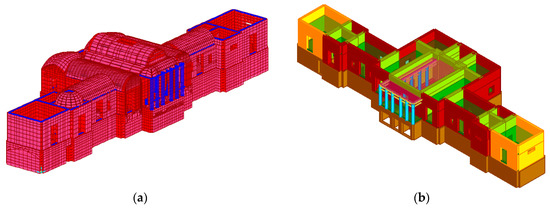
Figure 3.
(a)The SAP2000 and (b) TREMURI model of the case study building.
The second three-dimensional model of the building was developed by software TREMURI [11]. The method implemented in the software is based on the frame by macro elements (FME) approach. Therefore, the equivalent frame consists of vertical and horizontal macroelements, i.e., piers and spandrels, with 8 degrees of freedom to represent the bending rocking and the shear sliding mechanisms. The overlapping areas between horizontal and vertical elements, that are considered as undamaged masonry portions, are modeled as rigid for taking in account the real dimensions of the masonry components [30]. In this case, a nonlinear analysis was performed assuming an elastic-perfectly plastic with initial cracked elastic stiffness behavior for masonry piers. The formulation of the strength criteria for the three possible failure modes considered, that are flexure-rocking, sliding shear and shear-diagonal cracking, agrees with the Italian and European seismic codes recommendations [22,23].
Vaults and floors with steel beams and hollow tile are detected in the building as horizontal elements. Membrane finite elements with equivalent stiffness properties are employed to take into account the floor effect in the plane. In particular, for the floor with steel beams and hollow tiles, the equivalent horizontal stiffness was defined through the geometrical configuration and thickness.
Figure 3b shows the extruded view of the model developed with TREMURI software.
4. Analysis of Stresses under Gravity Loading
As a first step, the case study was analyzed for gravity loads in order to examine the level of stress within the walls of the building. The considered loads in this case are the building self-weights and the live loads. In Figure 4, the vertical compressive stresses reached at one of the surface of the shell elements are reported; it should be noted that the maximum value of stress, localized at the lower level, is equal to 0.39 MPa, while the mean value is about 0.20 MPa. High concentrations of stress can also be found at the corners, windows or openings. It is worth to underline that the color map in Figure 4 has been drawn taking 0.74 MPa, that is the design value of the compressive masonry strength obtained using a confidence factor (FC) equal to 1.35 and a partial safety factor (γM) equal to 2, as the highest absolute value in the color scale. As seen from Figure 4, most part of the structure remains under compression within permissible limits.
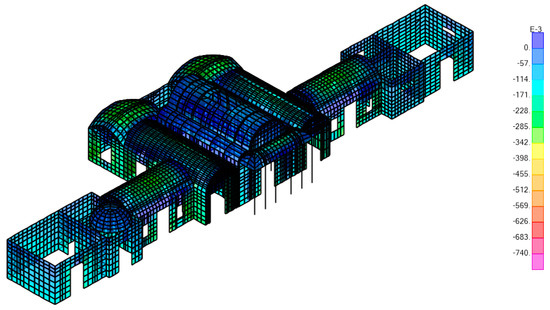
Figure 4.
Maximum normal compression stresses in the main walls of the building (N/mm2).
The comparison between experimental data and the stress distributions obtained from linear analyses under gravity loads has been employed to verify the reliability of both the values adopted for the unit weight and the geometrical layout. In this case, the experimental value of 0.25 MPa obtained from the single flat-jack is in good agreement with the value of 0.22 MPa obtained by the numerical model.
5. The Seismic Analysis
5.1. Methodology
The present paper focuses on the seismic assessment of a masonry historical building selected as a case study. It is well known that both linear and nonlinear analysis methods can be adopted for the ultimate limit state verification of masonry buildings, but sometimes it is not completely clear what significance of the results in the two cases is, or what their utility is for an upgrade design. Linear elastic methods include both equivalent static and modal analysis. The first one can be adopted in few cases for regular buildings and when the higher modes are not dominant in the response, that is unusual in historical constructions. Otherwise the linear dynamic approach by modal analysis is more general because it includes all significant modes introducing in the analysis the effect the dynamic response also for irregular constructions. The effect of the modes on the internal forces and deformations could be obtained with the combination rule of the square root of the sum of squares of modal quantities when the modes differ significantly with each other or using the complete quadratic combination rule in the case of closely coupled modes. The linear dynamic analysis leads to a high reliability of the results because the linear modeling of materials is based on a few parameters and the verifications refer to the strength performance using consolidated formulations. In case of an existing structure, the parameters that govern the linear behavior can be estimated for the specific case by in situ tests and surveys with a good reliability. The ductility performance can be considered only introducing the behavior factor, q, in the design spectrum, and contains all the uncertainties of the non-linear behavior of the structure, therefore the values of q suggested by the codes are only reliable for typical buildings but not for historical constructions that do not have a statistic significance.
Thus, a nonlinear approach can be an alternative to the linear analysis if the plastic reserve of the structure could be relevant. Currently, a quite consolidated methodology for the assessment of existing buildings is the nonlinear static analysis method. At the first stage of the analysis, the structure is subjected to vertical loads and then horizontal loads, with a prefixed shape, are applied with increasing magnitudes (push-over analysis). The result is the capacity curve of the entire structure, i.e., the base shear-displacement response curve constructed introducing the damage evolution in each element through the adequate modeling of the nonlinear behavior of the material or the elements, as already explained in the introduction. According to the recommendations of European and Italian building code [21,22] the analyses should be performed considering two load patterns in each main direction (X and Y). Usually, a first distribution proportional to the masses and a second one proportional to the product of the masses by the displacements of the corresponding first modal shape are adopted. These two distributions could be considered as representative of two limit states for the capacity of the building. Anyway more complex procedures are available for push-over analyses for taking into account the effect of higher modes if it is necessary [31]. The aim of the paper is to compare the results from a linear dynamic and a nonlinear static analysis applied to the case study, an historical and complex masonry building. The linear analysis was developed by a FE model with shell elements for walls and vaults. The results are in terms of stresses and strains in the material, providing very interesting information on damage concentration, importance of the walls and vaults connections, dynamic behavior. The nonlinear analysis was implemented by the equivalent frames method, which uses macroelements with lumped plasticity, considers the vaults only as masses and deformable floor connection for the walls. This last approach was widely used by engineers because the results of the model are simple to understand the global response of the structures and the walls that govern the ultimate state, correctly addressing the interventions.
The FE model with shell elements was developed with the software SAP2000, and a modal analysis was carried out to obtain the dynamic properties of the structure, i.e., periods of vibration, modal shapes, and modal participating mass ratios. Then, a linear dynamic analysis with response spectra was performed. The verification of the masonry panels was developed evaluating the capacity/demand (C/D) ratio with respect to the shear and bending moment.
The push-over analysis, with prefixed shapes of the horizontal forces, was performed adopting the equivalent frames model developed with the software TREMURI, which uses special monodimensional macroelements.
In order to compare the results of these different analyses a global index, the ratio between the maximum acceleration and the peak acceleration at the ground (PGA), adopted by the Italian building code for evaluating the seismic risk of existing structures, was calculated.
5.2. The Linear Dynamic Behavior
The dynamic properties of the structure, i.e., periods of vibration, modal shapes, and modal participating mass ratio (Mp), which is the ratio between the mass involved in each vibration mode and the total mass of the structure, were obtained through a modal analysis of the case study by software SAP2000.
Table 2 reports the first three vibration modes; it is possible to note that small participating mass ratios, that are 27%, 52% and 42%, respectively for the translational mode in Y direction, the translational mode in X direction and torsional mode, are involved.

Table 2.
Periods and modal participating mass ratios of the case study.
In the graphs of Figure 6a, the partial sum of Mp is drawn for the first 100 longitudinal and transversal modes. It can be noted that a total participating mass of 80–85% of the total mass is reached, but it is also remarkable that each mode gives a small contribution. Moreover, as 60% of the total mass is reached by the first eight modes, the increments become extremely small and lower than 1%. These finding are consistent with the mode shapes depicted in Figure 5. It is clear that macroelements of the monumental building move according to different local modes due to connections between large and small parts of the building in few points.
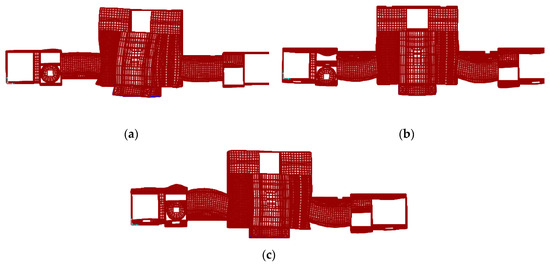
Figure 5.
Mode shapes of the case study: (a) Mode 1; (b) Mode 2; (c) Mode 3.
In the graph of Figure 6b, the participating mass ratios (Mp) associated to each vibration period, taking into account 100 modes, were reported. The distribution of Mp is compared with the elastic spectrum provided by the Italian Building code for Naples, for a returned period TR = 712 years and soil type B. In this case, the Mp is generally less than 5%. Eurocode 8 and the Italian Building Code [5,6] suggest to consider all vibration modes having a modal participating mass ratio higher than 5%; therefore, in this case, the total participating mass ratio was computed considering a subset of eight vibration modes. The results provide quite low values: in particular, in the longitudinal and transversal direction, the sum of Mp 5% is equal to 64.9% and 58%, respectively, as reported on the right side of Figure 6b. Thus, it can be highlighted that this subset is not fully significant to describe the behavior of the building.
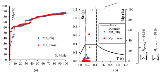
Figure 6.
(a) Distribution of the modal participating mass ratio; (b) participating mass ratios associated to vibration periods.
To compare the response with the elastic spectrum, it is divided into three ranges: the increasing branch, the plateau and the decreasing branch. The total participating mass ratio was computed for each range and reported on the top side of the graph in Figure 6b. It is possible to note that in this case, almost the total participating mass corresponds to the plateau.
5.3. The Response Spectrum Analysis
As highlighted in the previous section, the seismic response of the structure is strongly influenced by the irregular dynamic behavior, evidencing a probable failure of the building in macroelements which needs adequate procedures to consider the effective performance of the structure. Surely, a linear analysis is safe for the building because a local failure does not necessarily correspond to the ultimate limit state of the entire structure but it is individuated by the stress concentration. Nevertheless, the linear model was used to check the performance of the structure at the ultimate limit state.
The seismic action is evaluated by the elastic response spectrum provided by the Italian building code, for a returned period TR equal to 712 years and soil type B, as reported in Figure 7. An importance coefficient Cu equal to 1.5 corresponding to a building class III was considered since it was assumed a high occupancy for the building. The well known parameters used for the determination of the elastic acceleration spectrum are the following:
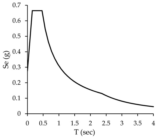
Figure 7.
Elastic response spectrum adopted for the case study.
- Hazard parameters: ag = 0.192 g; F0 = 2.41;
- Soil parameters: SS = 1.20; CC = 1.37; ST = 1.00; S = 1.20;
- Significant points of the spectrum: T*c = 0.34; TB = 0.155 s; TC = 0.464 s; TD = 2.37 s.
Moreover, an equivalent viscous damping factor ξeq equal to 5% and a behavior factor q equal to 2.25 were assumed.
The seismic action was applied combining the effect along the two main directions. The verification of the masonry panels was developed evaluating the capacity/demand (C/D) ratio with respect to the shear and bending moment. The capacity in shear is evaluated according to Equation (1):
where Vt and vs. are the horizontal strengths corresponding to the sliding and diagonal cracking of the panel, respectively. In particular, they are calculated as reported in Equations (2) and (3):
VRd = min (Vt;Vs),
Vt = l·t∙(1.5·τ0d)/b∙√(1 + σ0/(1.5·τ0d)),
Vs = l′·t·fvd,
In the previous equations l, t and l′ are, respectively, the width, the thickness and the length of the compresses zone of the panel while b is a coefficient, usually equal to 1.5, related to the panel slenderness. For the evaluation of the sliding horizontal strength, the masonry reference shear strength τ0d and the average vertical compressive stress σ0 were adopted. The first one (τ0d) was evaluated as in Equation (4) starting from the average masonry shear strength τ0 and adopting a partial safety factor of the masonry γm and a confidence factor FC equal to 2 and 1.35, respectively, since in this case a knowledge level 1 is considered. The latter has been defined as in Equation (5) where N is the normal action.
τ0d = τ0/γm∙FC,
σ0 = N/l·t,
Instead, for the evaluation of the diagonal cracking, horizontal strength and the design masonry shear strength fvd were adopted as reported in Equation (6):
where σn is the average compressive stress action on l′ (i.e., σn = N/l′·t).
fvd = (τ0 + 0.4σn)/γm∙FC,
The capacity in flexure for rocking failure can be evaluated as reported in Equation (7):
where fd = fm/γm∙FC, with fm being the masonry average compressive strength.
MRd = ((l2∙t∙σ0)/2)∙(1 − σ0/(0.85∙fd)),
The results provide that the Y direction is the weakest one. In Figure 8, the most critical panels for which the minimum safety factor is approximately 0.2 are circled and the corresponding results are briefly presented. It can be observed that the shear strength is the most lacking.
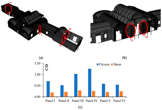
Figure 8.
Most vulnerable panels in Y (a) and X (b) direction; (c) C/D ratio for the most vulnerable panels.
For existing structures, the seismic risk of the building can be evaluated as the ratio between the maximum acceleration and the peak acceleration at the ground (PGA); in this case of ultimate limit state, this index results 0.23.
5.4. The Nonlinear Analysis
The seismic vulnerability evaluation of the case study was carried out also performing nonlinear static analyses by TREMURI software [11]. The FE model was loaded by gravity loads and then by monotonically increasing horizontal forces. It is worth underlining that a conventional pushover analysis, where the horizontal loads did not change with the analysis, was adopted.
The pushover analysis was implemented considering two distributions of horizontal forces, i.e., proportional to the masses and proportional to the first vibration mode, applied at the level of floors along the two main orthogonal directions X and Y. Taking into account the two verses and the accidental eccentricities (Ecc) of the mass center, a total of 24 load conditions of static forces were employed.
In Figure 9, the pushover curves corresponding to the worst load conditions in the two directions, respectively, are shown.
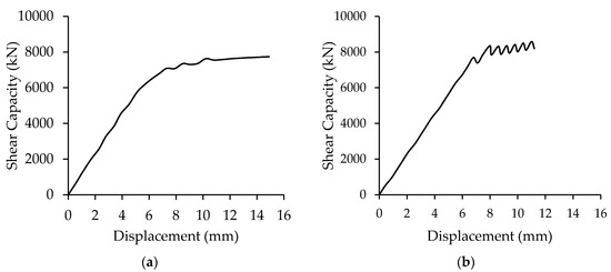
Figure 9.
Pushover curves for the worst load condition in the X (a) and Y (b) directions.
In Table 3, for the sake of brevity, only the results associated to the worst load conditions, respectively, for the X and Y directions are reported. In particular, it could be found the capacity displacement du and the demand diplacement dmax that are useful to perform the verification of the structure. The same result, i.e., the ratio between the capacity and the demand in terms of peak ground acceleration (PGA), is also reported through the parameter αu in order to develop a comparison with the results of the response spectrum analysis.

Table 3.
Results related to the worst load conditions deriving from pushover analysis.
From the results of the pushover analysis, it can be highlighted that the seismic check is not satisfied in both directions since the safety factors are less than one; however, the safety factor along the X direction (0.47) is slightly greater than the one in the Y direction (0.30). The latter suggests that the Y direction is the weaker one, as already underlined with the results of the response spectrum analysis.
The walls damaged by the earthquake in the numerical model (Figure 10) are the same as those obtained by the modal response spectrum analysis and also the same type of failure is detected. The global result of the nonlinear analysis gives an index of seismic risk higher than the one of the linear analysis confirming that the post elastic behavior can be an important contribution to the safety of the structure using the ductility and the consequent stress redistribution of the bearing elements.
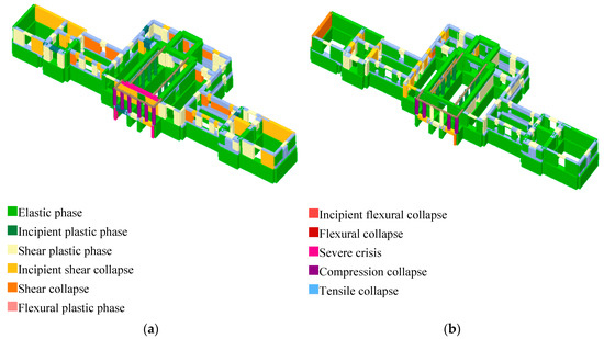
Figure 10.
Failure mode according to the worst condition in the X (a) and Y directions (b).
6. Conclusions
The complete understanding of the structural behavior and the seismic assessment of ancient monumental buildings is a difficult task. The study of “the astronomical observatory of Naples” presented in this paper highlighted many critical points in developing linear dynamic analysis using 2D FE elements or nonlinear static analysis with the equivalent frame macroelements, due to the type of analysis and models adopted. The following results can be summarized that give a general view of the results that can be typical of historical buildings:
- -
- The linear dynamic analysis underlines the importance of an irregular response of the structure due to its shape in plan or/and along the height, the presence of a deformable horizontal connection of the walls realized by the vaults;
- -
- The 2D model gives the results in terms of stresses allowing to understand the importance of a weakness in the connections between the walls and the role of openings;
- -
- The linear analysis gives reliable results also with a low level of knowledge and addresses an efficient design based only on the resistance resources of the structures, which could be more expensive but safe;
- -
- The nonlinear analysis allows to take into account the ductility of the elements using the post-elastic resources of the structure by an explicit evaluation; the failure of the structure is identified by a global parameter of its capacity that gives a more reliable evaluation of its safety level;
- -
- The static analysis does not allow to understand the role of the dynamic response and address the interventions only to improve strength or ductility but not global solutions for reducing the irregular response;
- -
- The macromodeling approach with equivalent frame gives nonlinear results more friendly to be analyzed with respect to nonlinear 3D or 2D FE elements but the uncertainties of the nonlinear response are concentrated in the model of the plastic hinges, and some elements like curved walls or vaults are excluded. The nonlinear analysis allows to use the post-elastic capacity of the elements, therefore it is not always an efficient instrument to address the interventions that improve the strength of the elements;
- -
- The comparison of the global index of the seismic risk C/D, that is the ratio between capacity and demand in terms of PGA, resulted as 0.23 from the linear analysis and 0.3 for the nonlinear one, pointing out that the nonlinear behavior allows to use more resources of the structure, giving a lower seismic risk.
Furthermore, the general comments provide some interesting results for the specific case which could be introduced. The results of the nonlinear static analysis give a lower level of seismic risk. However, they show a non-satisfactory behavior in both directions since the safety factors are less than one; in particular, the safety factor along the X direction (0.47) is slightly greater than the one in the Y direction (0.30), therefore the structure is globally not safe and needs an upgrading intervention, which is a typical result for so irregular a building made by old masonry, large vaults and a heavy stone facade. Therefore, strengthening measures are necessary and they can be better addressed using more than one type of model and analysis in the assessment procedure, because different results and information, all useful and often necessary in monumental buildings that are singular cases, are given by different approaches.
Author Contributions
Conceptualization, M.R.P. and A.D.A.; methodology, G.M.; software, A.D.A.; validation, A.D.A., M.R.P. and G.M.; formal analysis, A.D.A.; investigation, A.D.A.; writing—original draft preparation, A.D.A.; writing—review and editing, G.M.; supervision, M.R.P. All authors have read and agreed to the published version of the manuscript.
Funding
This research was carried out within the framework of the PON Research and Innovation 2014–2020, Axis I-Investments in Human Capital, MIUR notice AIM-“International Attraction and Mobility”-Line 1, Project: AIM 1823125-3—Cultural Heritage.
Acknowledgments
The authors acknowledge Arch. Liana De Filippis for her support in finding the historical information and realizing surveys and tests in situ.
Conflicts of Interest
The authors declare no conflict of interest.
References
- De Angelis, A.; Maddaloni, G.; Pecce, M.R. Seismic Vulnerability Assessment of a Monumental Masonry Building. In Proceedings of the 8th Euro-American Congress REHABEND, Granada, Spain, 24–27 March 2020. [Google Scholar]
- Brandonisio, G.; Lucibello, G.; Mele, E.; De Luca, A. Damage and performance evaluation of masonry churches in the 2009 L’Aquila earthquake. Eng. Fail. Anal. 2013, 34, 693–714. [Google Scholar] [CrossRef]
- Lourenço, P.B. Computations on historic masonry structures. Prog. Struct. Eng. Mater. 2002, 4, 301–319. [Google Scholar] [CrossRef]
- Braga, F.; Liberatore, D.; Spera, G. A computer program for the seismic analysis of complex masonry buildings. In Fourth International Symposium on Computer Methods in Structural Masonry; Pratolino, F., Pande, G.N., Middleton, J., Kralj, B., Eds.; EFN Spon: London, UK, 1997; pp. 309–316. [Google Scholar]
- Brencich, A.; Lagomarsino, S. A macro-elements dynamic model for masonry shear walls. In Fourth International Symposium on Computer Methods in Structural Masonry; Pratolino, F., Pande, G.N., Middleton, J., Kralj, B., Eds.; EFN Spon: London, UK, 1997; pp. 67–75. [Google Scholar]
- Casolo, S.; Milani, G. A simplified homogenization-discrete element model for the nonlinear static analysis of masonry walls out-of-plane loaded. Eng. Struct. 2010, 32, 2352–2366. [Google Scholar]
- Bertolesi, E.; Milani, G.; Lourenço, P.B. Implementation and validation of a total displacement non-linear homogenization approach for in-plane loaded masonry. Comput. Struct. 2016, 176, 13–33. [Google Scholar] [CrossRef]
- Roca, P.; Molins, C.; Marì, A.R. Strength Capacity of Masonry Wall Structures by the Equivalent Frame Method. J. Struct. Eng. 2005, 131, 1601–1610. [Google Scholar] [CrossRef]
- Rizzano, G.; Sabatino, R. Non-linear Static Analysis of Masonry Structures by means of Equivalent Frames Simplified Approach. In Proceedings of the 8th International Masonry Conference, Dresden, Germany, 4–7 July 2010. [Google Scholar]
- Pasticier, L.; Amadio, C.; Fragiacomo, M. Non-linear seismic analysis and vulnerability evaluation of a masonry building by means of the SAP2000 V. 10 code. Earthq. Eng. Struct. Dyn. 2008, 37, 467–485. [Google Scholar] [CrossRef]
- Lagomarsino, S.; Penna, A.; Galasco, A.; Cattari, S. TREMURI program: An equivalent frame model for the nonlinear seismic analysis of masonry buildings. Eng. Struct. 2013, 56, 1787–1799. [Google Scholar] [CrossRef]
- D’Altri, A.M.; Sarhosis, V.; Milani, G.; Rots, J.; Cattari, S.; Lagomarsino, S.; Sacco, E.; Tralli, A.; Castellazzi, G.; de Miranda, S. Modeling Strategies for the Computational Analysis of Unreinforced Masonry Structures: Review and Classification. Arch. Comput. Methods Eng. 2020, 27, 1153–1185. [Google Scholar] [CrossRef]
- Zeris, C.; Vintzileou, E. Seismic Analysis of Masonry Buildings: Numerical Modeling. In Encyclopedia of Earthquake Engineering; Springer: Berlin/Heidelberg, Germany, 2014. [Google Scholar]
- Lagomarsino, S.; Modaressi, H.; Pitilakis, K.; Bosjlikov, V.; Calderini, C.; D’Ayala, D.; Benouar, D.; Cattari, S. PERPETUATE project: The proposal of a performance-based approach to earthquake protection of cultural heritage. Adv. Mater. Res. 2010, 133–134, 1119–1124. [Google Scholar] [CrossRef]
- Magenes, G.; Della Fontana, A. Simplified non-linear seismic analysis of masonry buildings. In Proceedings of the 5th International Masonry Conference, London, UK, 12–14 October 1998; Volume 8, pp. 190–195. [Google Scholar]
- Penelis, G. An efficient approach for pushover analysis of unreinforced masonry (URM) structures. J. Earthq. Eng. 2006, 10, 359–379. [Google Scholar] [CrossRef]
- Clementi, F.; Gazzani, V.; Poiani, M.; Mezzapelle, P.A.; Lenci, S. Seismic Assessment of a Monumental Building through Nonlinear Analyses of a 3D Solid Model. J. Earthq. Eng. 2018, 22, 35–61. [Google Scholar] [CrossRef]
- Betti, M.; Vignoli, A. Modelling and analysis of a Romanesque church under earthquake loading: Assessment of seismic resistance. Eng. Struct. 2008, 30, 352–367. [Google Scholar] [CrossRef]
- Preciado, A. Seismic vulnerability and failure modes simulation of ancient masonry towers by validated virtual finite element models. Eng. Fail. Anal. 2015, 57, 72–87. [Google Scholar] [CrossRef]
- Preciado, A.; Sperbeck, S.T. Failure analysis and performance of compact and slender carved stone walls under compression and seismic loading by the FEM approach. Eng. Fail. Anal. 2019, 96, 508–524. [Google Scholar] [CrossRef]
- Lourenço, P.B.; Krakowiak, K.J.; Fernandes, F.M.; Ramos, L.F. Failure analysis of Monastery of Jeronimos, Lisbon: How to learn from sophisticated numerical models. Eng. Fail. Anal. 2007, 14, 280–300. [Google Scholar] [CrossRef]
- Ministerial Decree of Public Works (M.D.) (14/01/2008). New Technical Codes for Constructions; G.U. n. 29 (4/2/2008); Ministerial Decree: Rome, Italy, 2008. [Google Scholar]
- Eurocode 8—EN 1998-3. Design of structures for earthquake resistance. In Part 3: Assessment and Retrofitting of Buildings; CEN: Brussels, Belgium, 2005. [Google Scholar]
- Italian Building Code. Guidelines: Assessment and Mitigation of Seismic Risk of Cultural Heritage with Reference to the 2008 Italian Building Code [Linee Guida per la Valutazione del Rischio Sismico del Patrimonio Culturale Allineate alle Nuove norme Tecniche per le Costruzioni]; G.U. No. 47; Italian Building Code: Rome, Italy, 2011. (In Italian) [Google Scholar]
- Giordano, A.; Mele, E.; De Luca, A. Modelling of historical masonry structures: Comparison of different approaches through a case study. Eng. Struct. 2002, 24, 1057–1069. [Google Scholar] [CrossRef]
- Mele, E.; De Luca, A.; Giordano, A. Modelling and analysis of a Basilica under earthquake loading. J. Cult. Herit. 2003, 4, 355–367. [Google Scholar] [CrossRef]
- Degli Abbati, S.; D’Altri, A.; Ottonelli, D.; Castellazzi, G.; Cattari, S.; de Miranda, S.; Lagomarsino, S. Seismic assessment of interacting structural units in complex historic masonry constructions by nonlinear static analyses. Comput. Struct. 2019, 213, 51–71. [Google Scholar] [CrossRef]
- Marcari, G.; Fabbrocino, G.; Lourenço, P.B. Mechanical properties of tuff and calcarenite stone masonry panels under compression. In Proceedings of the Eight International Masonry Conference, International Masonry Society, Dresden, Germany, 4–7 July 2010; Technische Univesität Dresden: Dresden, Germany, 2010. [Google Scholar]
- Computers and Structures. SAP2000 Version 18; Computers and Structures: Walnut Creek, CA, USA, 2016. [Google Scholar]
- Formisano, A.; Marzo, A. Simplified and refined methods for seismic vulnerability assessment and retrofitting of an Italian cultural heritage masonry building. Comput. Struct. 2016, 180, 13–26. [Google Scholar] [CrossRef]
- Antoniou, S.; Pinho, R. Advantages and limitations of adaptive and non-adaptive force-based pushover procedures. J. Earthq. Eng. 2004, 8, 497–522. [Google Scholar] [CrossRef]
Publisher’s Note: MDPI stays neutral with regard to jurisdictional claims in published maps and institutional affiliations. |
© 2020 by the authors. Licensee MDPI, Basel, Switzerland. This article is an open access article distributed under the terms and conditions of the Creative Commons Attribution (CC BY) license (http://creativecommons.org/licenses/by/4.0/).