Article

Analytical Model for Air Flow into Cracked Concrete Structures for Super-Speed Tube Transport Systems

Department of Civil and Environmental Engineering, College of Engineering, Wonkwang University, Iksan 54538, Korea
*
Author to whom correspondence should be addressed.
Infrastructures 2019, 4(4), 76; https://doi.org/10.3390/infrastructures4040076
Submission received: 5 November 2019 / Revised: 12 December 2019 / Accepted: 13 December 2019 / Published: 17 December 2019
(This article belongs to the Special Issue Innovate, Research, and Maintain Transportation Infrastructure)

Abstract

:
The super-speed tube transport (SSTT) system, which enables high-speed transportation in a partially vacuumed tube by minimizing the air resistance, is drawing attention as a next-generation transportation system. To evaluate the applicability of concrete as a material for the system, the effect of cracks on the airtightness of the system needs to be considered. This study aims to establish an analytical relationship between the cracks induced on a concrete tube structure and the system airtightness. An analytical model for the leakage rate through the concrete cracks is first applied to establish a differential equation, which can help determine the air flow rate into the concrete tube structure through the cracks. A mathematical formula for predicting the internal pressure changes over time in the concrete tube structure is then derived. The effect of crack development on the system airtightness is assessed through parametric analysis and a crack index for describing the extent of crack development is proposed by investigating the correlation with the system airtightness. Finally, assuming that the cracks due to external loadings are closely related to the displacement, the correlation between displacements and the airtightness of concrete tube structures is demonstrated through a set of experimental tests. As a result, the necessity of crack analysis for evaluation of the airtightness performance is emphasized.

Graphical Abstract

1. Introduction

The super-speed tube transport (SSTT) system, which helps to minimize the air resistance of vehicles by keeping the pressure inside the tunnel or tube structure much lower than the atmospheric pressure (Figure 1), is drawing attention as a next-generation transportation system owing to its high efficiency and environmental friendliness [1,2,3,4]. In addition to general design requirements for the stiffness and strength with respect to the design loads, such as vehicle loads, the tube structure of an SSTT system should have the capability of maintaining the internal air pressure level, which is initially lowered. Materials with lower air permeability, such as steel, could be more effective for enhancing the air tightness performance level of tube structures. However, this study considers concrete as a more viable and relevant material for an SSTT system based on several reasons. The concrete can be poured and cast into any shape, which increases workability of concrete over steel. Concrete structures have fewer connection than steel structures, thereby exhibiting better airtightness performance. Moreover, concrete is the material that is often locally sourced and the construction cost associated with concrete is lower than the materials such as steel. These are major advantages associated with the vacuum tube transportation system, generally aiming for long-distance transportation.
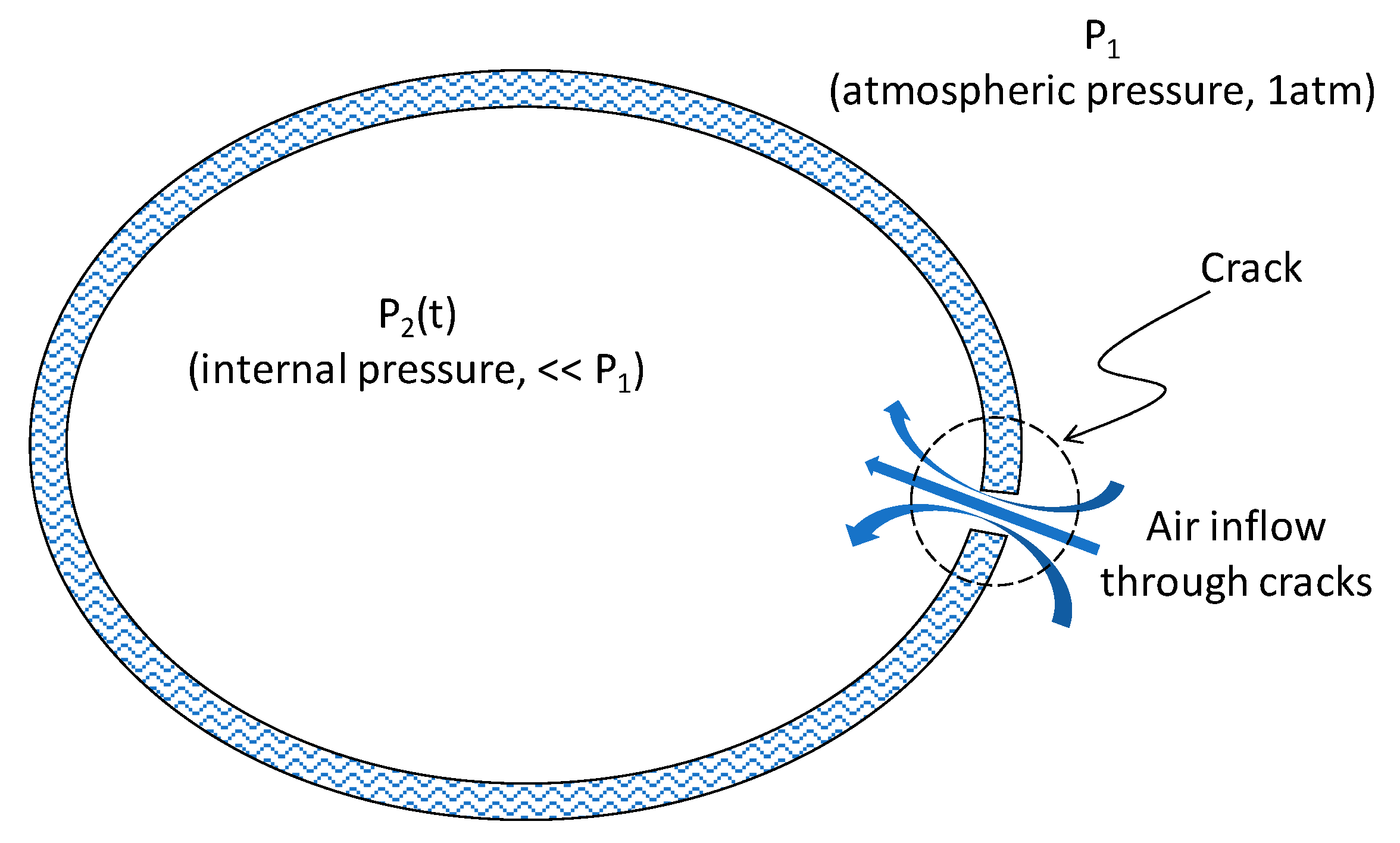
The suitability of concrete as a material for the SSTT system has been previously studied and can be found in the literature. Park et al. [2] developed a mathematical model for describing the air inflow behavior into a partially vacuumed tube structure and examined the effect of design variables such as material permeability, thickness, and diameter of the tube structure. In addition, they experimentally investigated the effects of joints and connections of the concrete tube structure on the system airtightness. Park et al. [4] conducted a probabilistic analysis for estimating the airtightness performance level of an SSTT system. However, these studies did not consider the effect of cracks that could occur on concrete structures. The occurrence of cracks on concrete structures can be due to many factors such as external loadings, shrinkage, uneven settlement, and/or heat of hydration [5]. The current design standard applied to concrete structures considers the generation of cracks on concrete under the service load [6]. The occurrence of cracks on the tube structure of an SSTT system may cause rapid inflow of outside air, which in turn can significantly affect the airtightness of the system (Figure 2). To design tube structures and to determine the resulting vacuum pump capacity, it is necessary to predict the changes in the pressure inside the tube due to the air inflow through the cracks. To this end, a quantitative relationship between the generated cracks and the resulting inflow rate needs to be determined.
This study aims to establish a relationship between the cracks developed on a concrete tube structure and the system airtightness. Following a review of models for predicting a gas leakage rate through concrete cracks, an analytical formula is derived to describe the internal pressure change of a SSTT system due to crack development. Using the model developed, the impact of a variation in the crack parameters on the system airtightness is investigated by performing parametric analyses. In the end, a comparison analysis is performed to establish a crack index that shows the most correlation with the system airtightness and could describe the degree of the developed cracks at the same time.

2. Development of Analytical Model for Air Inflow through Cracks

The flow of fluid due to the pressure difference between the inlet and outlet air flow through a gap with a certain area can be expressed using Bernoulli’s theorem [7]. However, this approach cannot be directly applied to the case of SSTT structures because several crucial variables that directly affect the air flow, such as friction, viscosity, and temperature [8], cannot be explicitly considered. In addition, the individual effects of several crack-related variables, such as the width, length, and number of cracks, cannot be considered in the model. This could lead to significant errors in calculating the rate of change of internal pressure.
Many studies have been conducted on gas leakage from cracks in concrete structures [9,10,11,12]. In these studies, formulae were developed to predict the leakage rate by theoretically establishing a basic formula and subsequently modifying it by conducting experimental tests. Soppe and Hutchinson [8] validated these formulae by performing experimental tests on the gas leakage rates for a series of concrete walls, on which cracks were forced to develop under uniaxial and biaxial loadings. Among the models investigated, the models proposed by Rizkalla et al. [9] and Suzuki et al. [10] were found to be the most accurate.
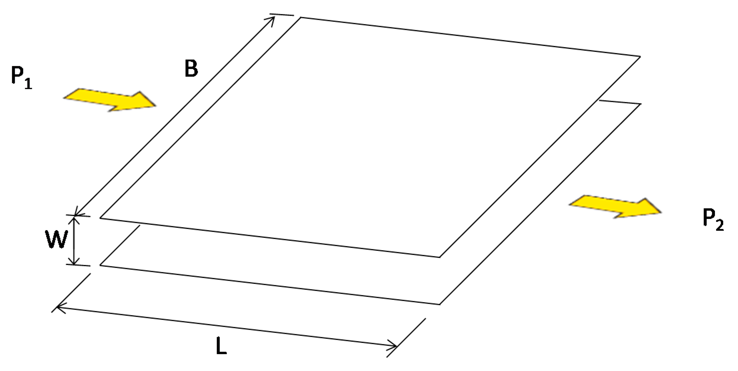
Suzuki et al. [10] proposed a formula for describing the gas flow through cracks, as shown in Figure 3. The gas flow rate due to the difference in the pressures P1 and P2 ( 0.8 × 10 5   Pa P 1   and   P 2 1.2 × 10 5   Pa ) at both ends of the two parallel plates with a gap W, length L, and breadth B can be given as follows.
Q = α · W 3 P 1 P 2 μ L
where μ is the dynamic viscosity associated with the gas flow, and α is a constant, which is experimentally determined. This formula cannot be applied to this study because the model is only valid for a particular range of pressure (i.e., 0.8 × 10 5   Pa P 1     and   P 2 1.2 × 10 5   Pa ) of the inlet and outlet air flow, as this study deals with the case wherein the internal pressure of the SSTT structure is as low as 0.1 atm.
Nevertheless, Rizkalla et al. [9] proposed a formula for estimating the flow rate for the case shown in Figure 3, as follows.
P = P 1 2 P 2 2 L = C 1 · | P 2 Q B | 2 n
where C1 and n are constants, determined by conducting experimental tests. If the above equation is applied to the case of cracks on concrete structures, B can be replaced with the length of the crack, W with the crack width, and L with the thickness of the structure on which the crack occurs. However, as multiple cracks can occur in a concrete structure, the constants in Equation (2) were experimentally determined as follows:
C 1 = ( k n 2 ) ( μ 2 ) n ( RT ) n 1 · 1 1.42 N · W avg 3
n = 0.195 ( N · W avg 3 ) 0.063 (   W avg   in   ft . )
k = 8.702 × 10 6 ( N · W avg 3 ) 0.367 (   W avg   in   ft . )
where R is the gas constant, and T is the absolute temperature. Note that the constants n and k in Equations (4) and (5), respectively, are determined based on experiments, and Wavg is measured in feet. Equation (2) can be applied if the pressure difference between the inlet and outlet air flow is constant regardless of the time. If this is expressed in terms of the air flow rate, the following equation can be written.
The above equation can be rewritten by substituting C 2 = B ( C 1 L ) 1 2 n , as follows:
Q = B P 2 ( P 1 2 P 2 2 C 1 L ) 1 2 n
Q = C 2 P 2 ( P 1 2 P 2 2 ) 1 2 n
For SSTT structures, the atmospheric pressure corresponding to P1 in Equation (7) is constant assuming that the temperature and latitude are constant. However, the internal pressure of an SSTT structure increases with time as the air flows into the structure through cracks, because the internal volume of the SSTT structure is limited. Therefore, P2 is a function of time, and Equation (7) can be expressed as follows:
Q ( t ) = C 2 P 2 ( t ) ( P 1 2 P 2 ( t ) 2 ) 1 2 n
Because the increase in the internal pressure is proportional to the air inflow, i.e., P 1 Q = dP 2 dt V 2 (where V2 denotes the internal volume of the SSTT structure), the following equation can be written:
P 1 C 2 V 2 · P 2 ( t ) ( P 1 2 P 2 ( t ) 2 ) 1 2 n = dP 2 dt
By substituting C 3 = P 1 C 2 V 2 and r = 1 2 n , Equation (9) becomes a differential equation as follows:
C 3 dt = P 2 ( t ) ( P 1 2 P 2 ( t ) 2 ) r · dP 2 ( t ) .  
On solving the differential equation by taking the integrals, the internal pressure at time t can be expressed as follows:
P 2 ( t ) = P 1 2 { 2 ( r 1 ) ( C 3 t + C ) } 1 1 r
With an initial condition that the initial internal pressure of the structure is Pi, the constant C in Equation (11) can be determined as follows:
C = ( P 1 2 P i 2 ) 1 r 2 ( r 1 )

3. Investigation of Crack Effect on the Air Inflow

Although no detailed design of an actual operational SSTT has been made, a prototype structure has been defined, as shown in Figure 4, to conduct the relevant research [13]. The prototype structure had a circular cross-section with a diameter of 4.0 m and a thickness of 0.25 m, determined under the assumption that the transport pod is carrying a single cargo container weighing 310 kN.
The system was to be constructed as a multi-span simply supported bridge-type structure, with span lengths of 30 m, 35 m, and 40 m. The target internal pressure for operation was defined as 0.1% of the atmospheric pressure.
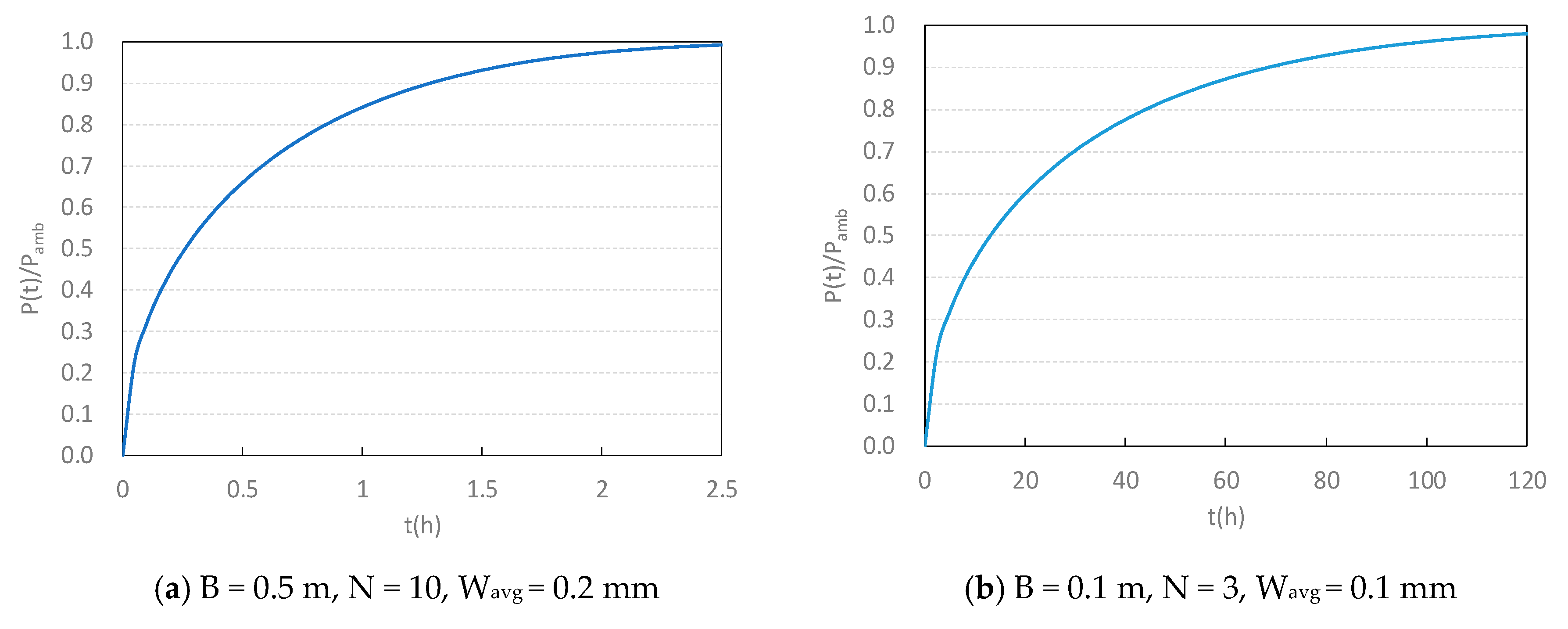
According to Equations (2)–(12), the air inflow behavior through the cracks was found to be closely related to three crack parameters: the average crack width (Wavg), crack length (B), and number of cracks (N). Figure 5a shows the change in the internal pressure over time, which was initially decreased to 0.001 atm, for the developed model for internal pressure prediction considering crack formation. Here, the total length of the cracks was 0.5 m; the number of cracks was 10; and the average crack width was 0.2 mm per unit length of the tube structure. A steep increase in the internal pressure was observed as it reached 0.8 atm within an hour.
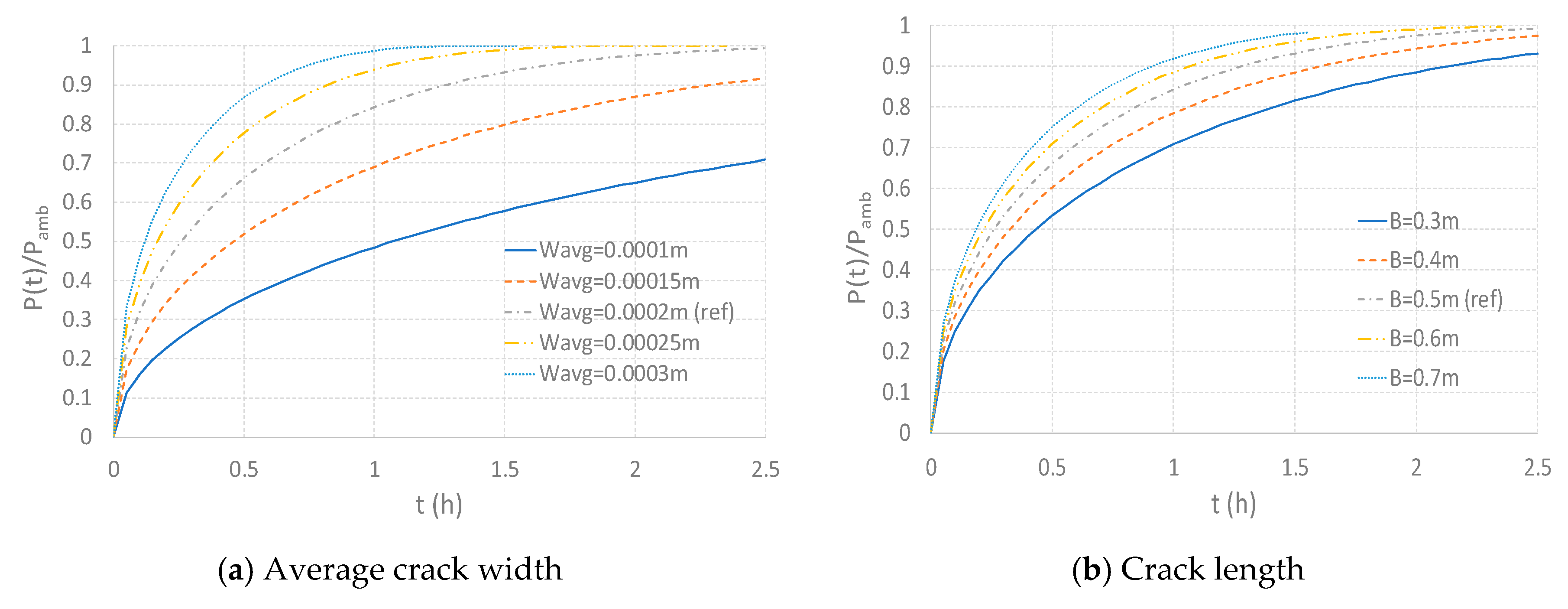
The increase tendency of the internal pressure of the SSTT structure depended on the degree of crack development. For example, Figure 5b shows the change in the internal pressure over time. Here, the total length of the cracks was 0.1 m; the number of cracks was three; and the average crack width was 0.1 mm per unit length of the tube structure. In this case, the time required for the internal pressure to increase to 0.8 atm was more than 40 times that shown in Figure 5a. It should be noted that the effect of the degree of crack development should be investigated because the internal-pressure-change curves differed depending on the values of the crack parameters. In practice, it was necessary to limit the number of possible cracks for a safe operation of the SSTT system. However, the focus of this study was on the investigation of the effect of cracks on the system airtightness. Therefore, a sensitivity analysis was performed to observe the effects of the crack parameters regardless of the target airtightness performance of the system. The baseline values of the crack parameters were determined for the sensitivity analysis as follows. The total length of the cracks was 0.5 m; the number of cracks was 10; and the average crack width was 0.2 mm per unit length of the tube. Each parameter was then independently varied over a specific range to investigate its effect on the system airtightness. It was assumed that both the ends of the tube structure were ideally sealed permitting no air inflow. Figure 6a shows the increase in the internal pressure for average crack widths ranging from 0.1 mm to 0.3 mm. A significant change in the system airtightness was observed depending on the crack width Wavg, as the time required for the internal pressure to increase to 0.5 atm was approximately 0.1 h for the case with Wavg= 0.3 mm, and 1.0 h for the case with Wavg = 0.1 mm. Figure 6b,c show the effects of the total crack length ranging from 0.3 m to 0.7 m and the number of cracks ranging from 6 to 14 on the system airtightness, respectively.
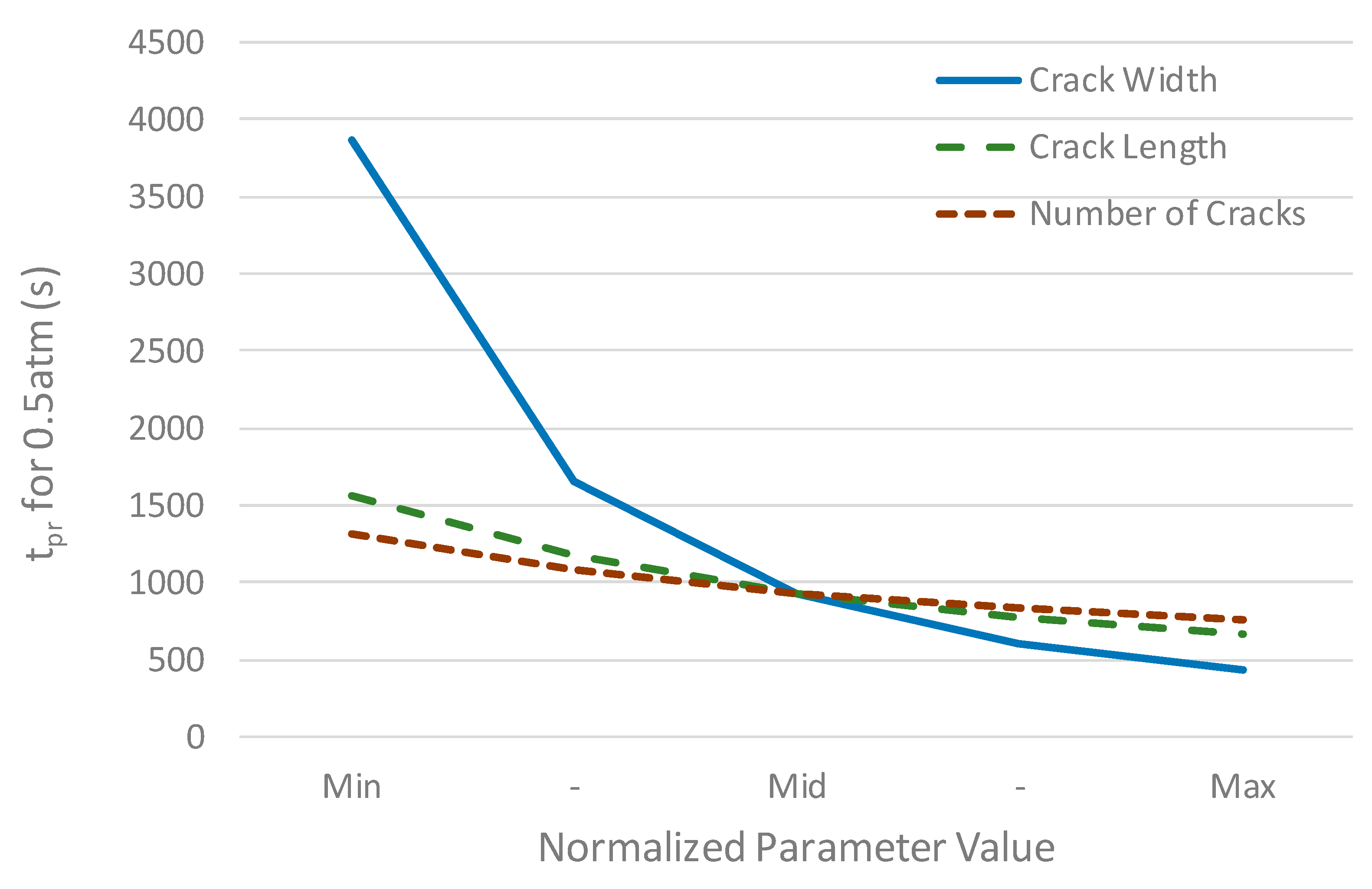
Among the three parameters, the average crack width was found to have the greatest effect on the airtightness, as it corresponded to the highest pressure increase rate. This trend was more apparent when comparing the time taken for the internal pressure to reach a certain level; this time was denoted as tpr. For practical purpose, tpr could be used as an indicator for system airtightness [2,4]. Figure 7 shows the time required for the internal pressure to increase to 0.5 atm with respect to the variations in the crack parameters, wherein the crack width exhibited the most rapid decrease within the normalized range of the parameters.
It should be noted that the ranges of the parameters in the sensitivity analysis performed in this study were determined by experience and intuitive judgement. In fact, the occurrence of cracks in concrete structures due to external loads was highly uncertain and measuring them was a very difficult task. Nevertheless, the system airtightness was believed to be highly sensitive to the degree of crack generation. Consequently, it was important to establish a crack index that can quantitatively express the generation of cracks in order to set the limit states for the cracks considering the target performance of the system.

4. Definition of Crack Index for Air-Tightness of Tube Structures

The parameters that help describe the status of the cracks in the Rizkalla leakage model are the average crack width, total crack length, and number of cracks. In the previous section, it is shown that the values of these parameters were inversely proportional to the system airtightness measured in terms of the time required for the internal pressure to reach a specified value. Although the three parameters may be defined independently as crack indices, defining a single crack index that can collectively consider all of them would facilitate the design and analysis of the SSTT system. Considering the input type of the parameters for the Rizkalla leakage model, it would be a rational approach to define the crack index as the product of the crack length, number of cracks, and cube of the average crack width. However, crack indices having different powers for the crack width were compared to investigate their applicability, as follows.
CI n = B · N · W avg n
where n = 1, 2, 3, or 4. Several combinations of the three parameters were chosen, and the airtightness corresponding to each combination was evaluated to investigate the correlation between the crack indices and the system airtightness. The system airtightness was measured corresponding to the time required for the internal pressure to reach a specified value, denoted as Ppr hereafter. Table 1 lists the ranges of each parameter.
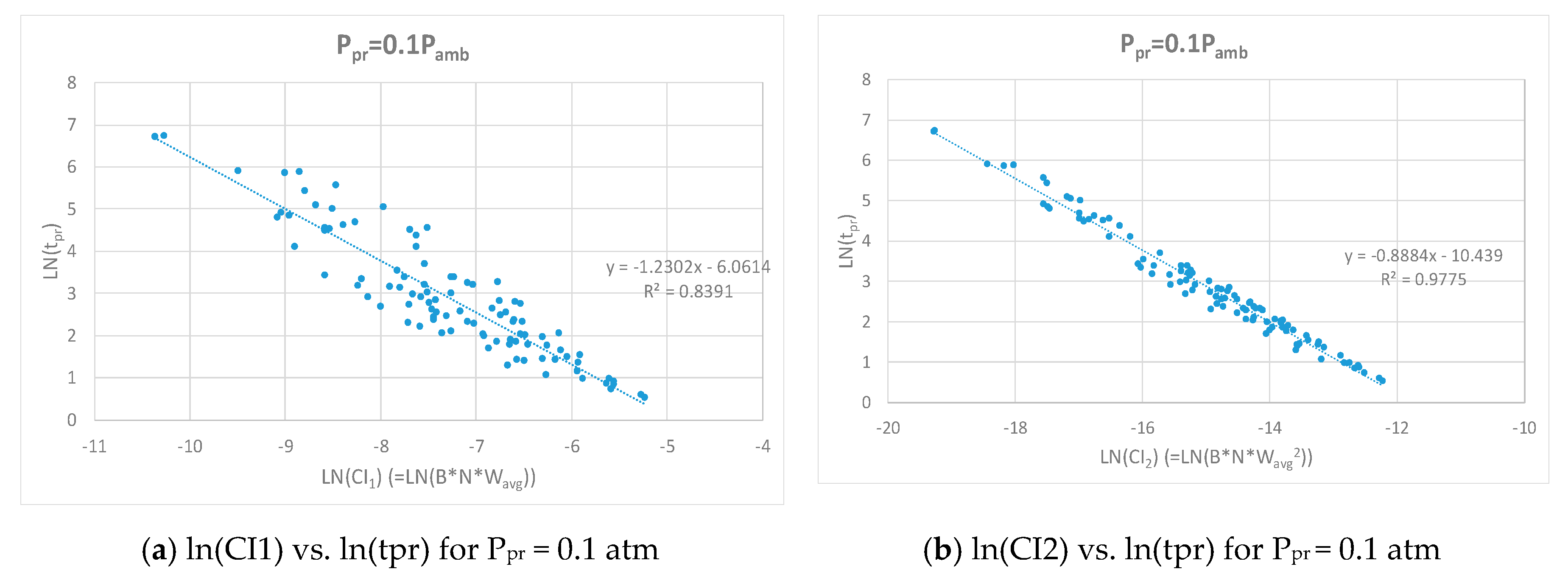
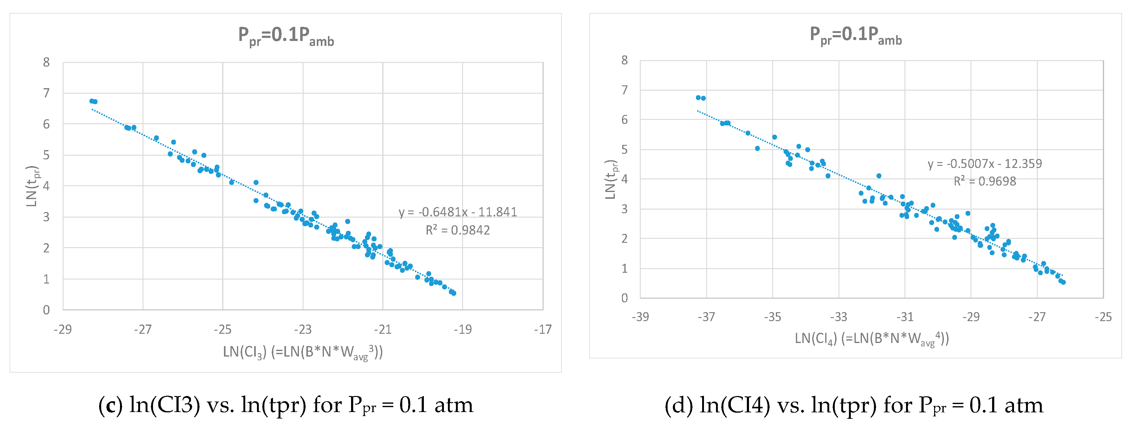
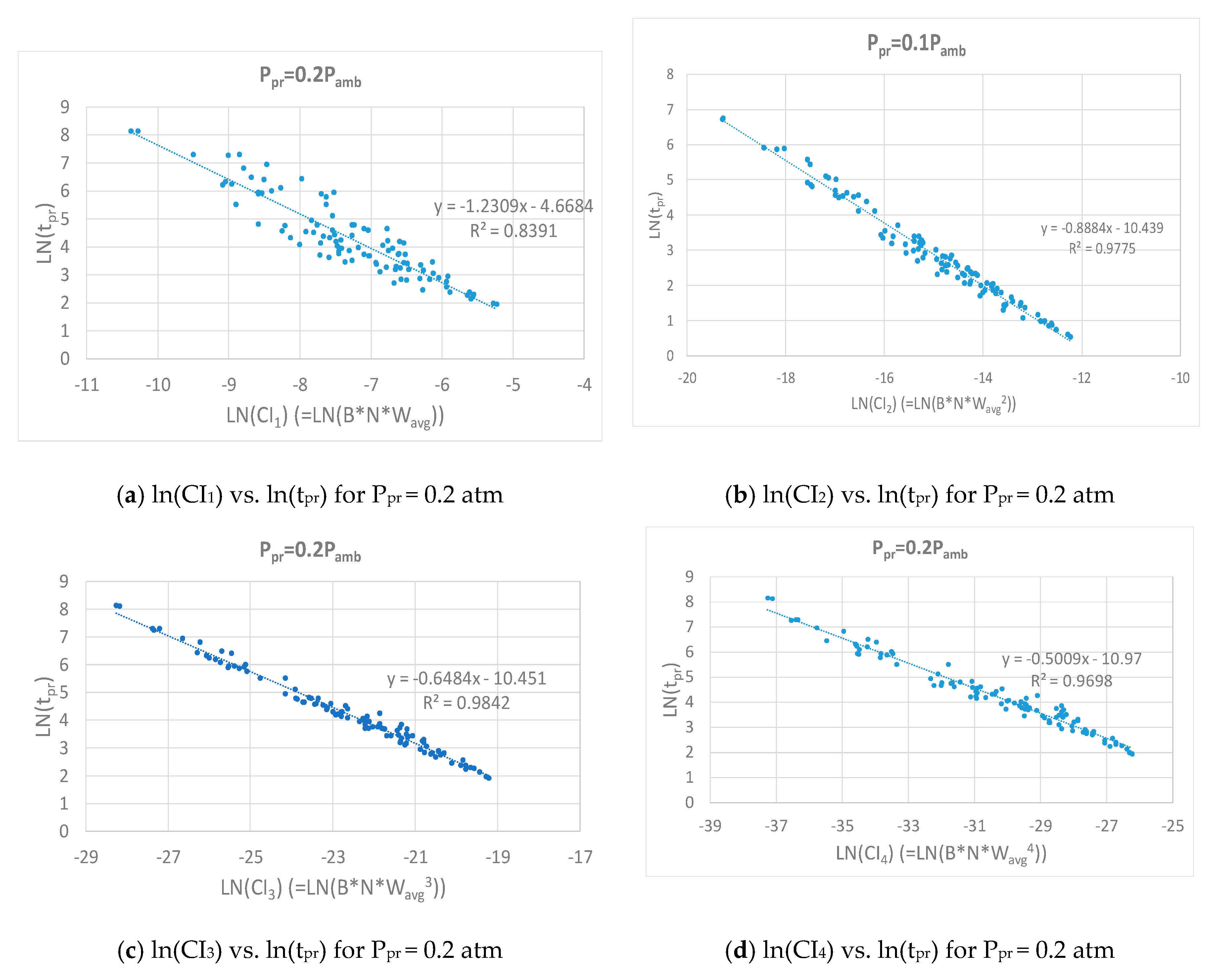
It was assumed that the total crack length was uniformly distributed in the range of 0.1–0.7 m per unit length of the tube structure; the number of cracks in the range of 1–10; and the average crack width in the range of 0.1–1.0 mm. A total of 100 combinations of the parameters were made, and the time for the internal pressure to reach a certain level, i.e., tpr, was determined for each combination. Figure 8 and Figure 9 show the logarithm distributions of tpr for CI1 to CI4, corresponding to target pressure levels of 0.1 atm and 0.2 atm, respectively. While all the indices showed an inverse proportionality with tpr, CI3 had a stronger correlation with tpr than other CIs. The coefficient of determination for the regression analysis corresponding to CI3 was found to be 0.9842, which was the highest among the four crack indices. This was consistent with the input format of the parameters for the Rizkalla leakage model. Therefore, it was concluded that defining CI3 as the crack index was the most reasonable choice for evaluating the airtightness of the SSTT system. The expression for the same is as follows:
CI = B · N · W avg 3
Unlike other typical concrete structures, the SSTT system made of concrete required consideration of the effect of cracks on the system airtightness at the design stage. The analysis results of this study show that it was essential to establish criteria for allowable cracks for the design of SSTT systems to ensure airtightness performance, because the system airtightness was found to be highly sensitive to the degree of crack development. The crack index proposed in this study can be effectively used to provide information required to set the limit states considering the target performance of the system.

5. Correlation between Cracks and Airtightness: Experimental Demonstration

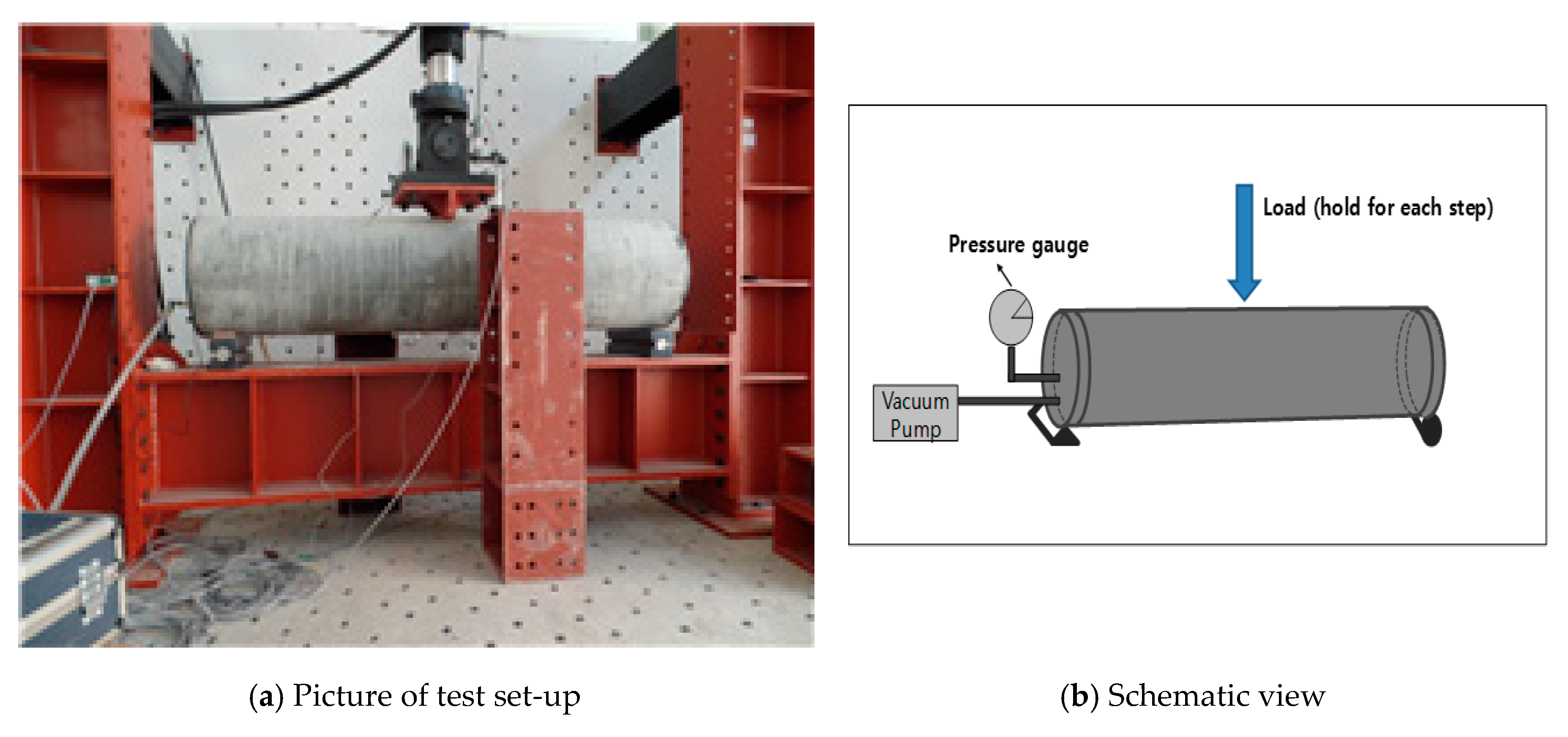
In order to establish the relationship between the cracks and the airtightness by experiment, it would be essential to obtain the values of crack parameters described above. However, it is very difficult to accurately measure the size and width of all cracks in a concrete structure. The displacement could be assumed as an indicator referring to the amount of cracks formed due to application of external loads. Likewise, airtightness performance could be described by the effective intrinsic air permeability (k). The concept that relates effective intrinsic air permeability with system airtightness is described by Park et al. [2]. Therefore, the correlation between cracks and airtightness is to be investigated indirectly by observing the relationship between the effective intrinsic permeability (k) and the displacement of concrete tube structures in this study. Four identical concrete tube structures with a circular tube cross section were prepared for the experimental test and named CIR01, CIR02, CIR03 and CIR04, respectively. The smaller dimension of the structure was used in our study because it would be very difficult to conduct an experimental study for a large tube structures as for the analysis and also we can scale up the dimension of the structure anytime if the trend of the airtightness was validated once. The size of each structure used in our study was 195 mm × 35mm × 2000mm (inner diameter × thickness × length). The compressive strength of the concrete used in the test structure was 40 MPa. Steel plates were attached to both ends of each structure to prevent air from entering in the longitudinal direction. A vacuum pump was then connected to the test structure to control the pressure inside the structure and a pressure gauge was also attached for monitoring the pressure inside the structure as shown in Figure 10.
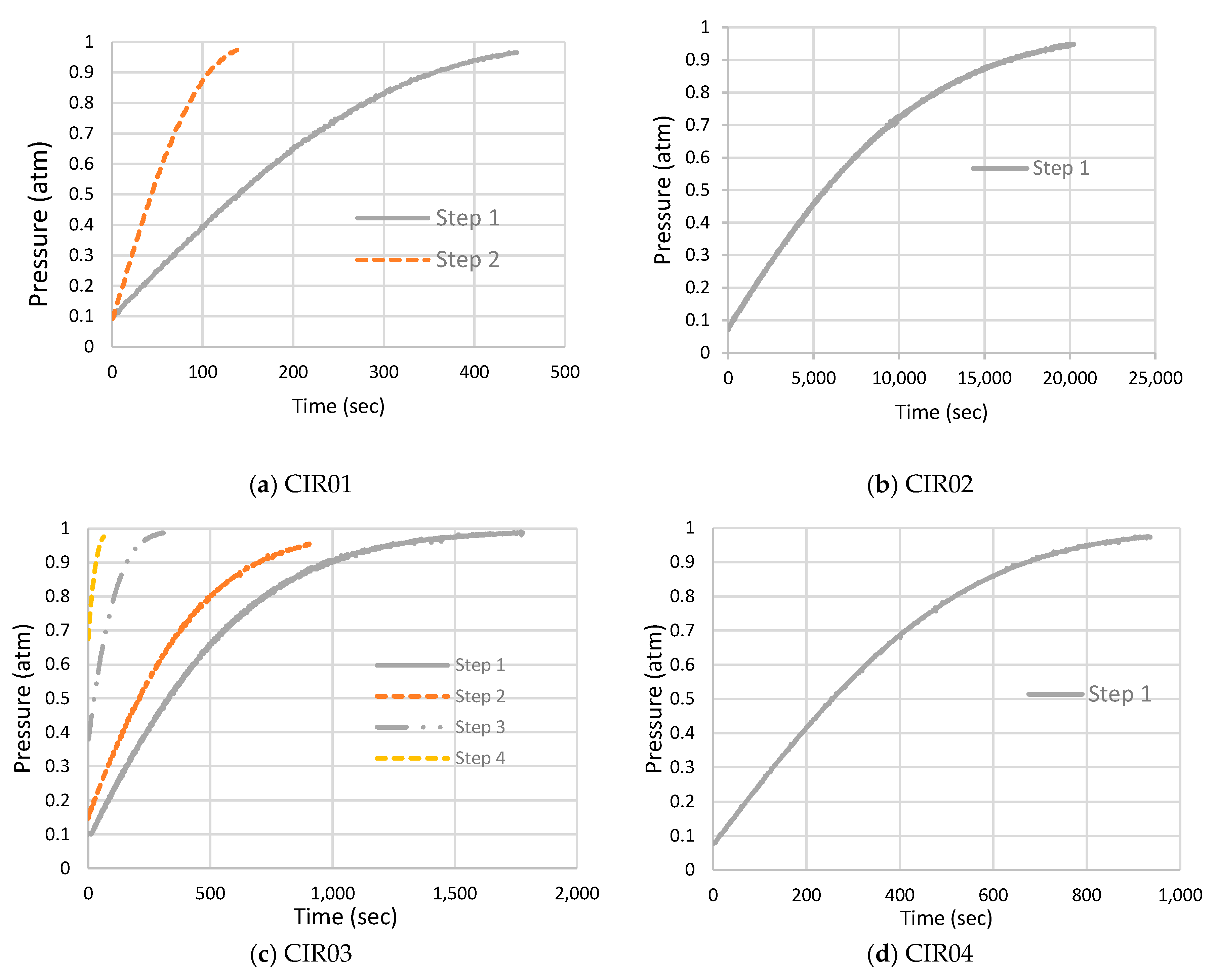
For evaluating the airtight performance of a structure with cracks, a vertical concentrated quasi-static loading was applied to the center of the tube, causing cracks in the structure. The gradually increasing load was stopped when noticeable cracks occurred in the structure and the vertical displacement of the top of the tube center was maintained. The airtightness test was then carried out in such a way that the pressure inside the tube was lowered until it reaches 0.1 atm, and the valve that was connected to the vacuum pump was closed. The pressure change inside the tube with time was then monitored using the pressure gauge attached to the tube. When this process was over, the loading was increased to cause additional displacement at the center and cracks in the structure, and the airtightness test was repeated. There were not many loading steps available in this test because in many cases a rapid decrease in the airtightness occurred due to sudden progress of the cracks. As a result, two loading steps were available for CIR01, one for CIR02, four for CIR03, and one for CIR04. Figure 11 shows the pressure change with time for the four test structures. Park et al. [2] presented a concept of effective intrinsic air permeability, which indicated the equivalent system airtightness of a structure with discontinuous region such as joints or cracks. In other words, the following expression [2] could be used to obtain the value of the effective intrinsic air permeability. The expression mentioned on Equation (11) would have been used to define the airtightness of the system thorough experimental study but couldn’t be used as its application constituted a difficult task because it can only be used after the crack parameters is known. Instead, we used Equation (15) along with the experimental results for determining the value of the effective intrinsic air permeability, which indicates the airtightness of the system, that best matches each plots shown in Figure 11.
P t = P o · 1 + C 1 · exp ( kAP o μ hV · t ) 1 C 1 · exp ( kAP o μ hV · t )
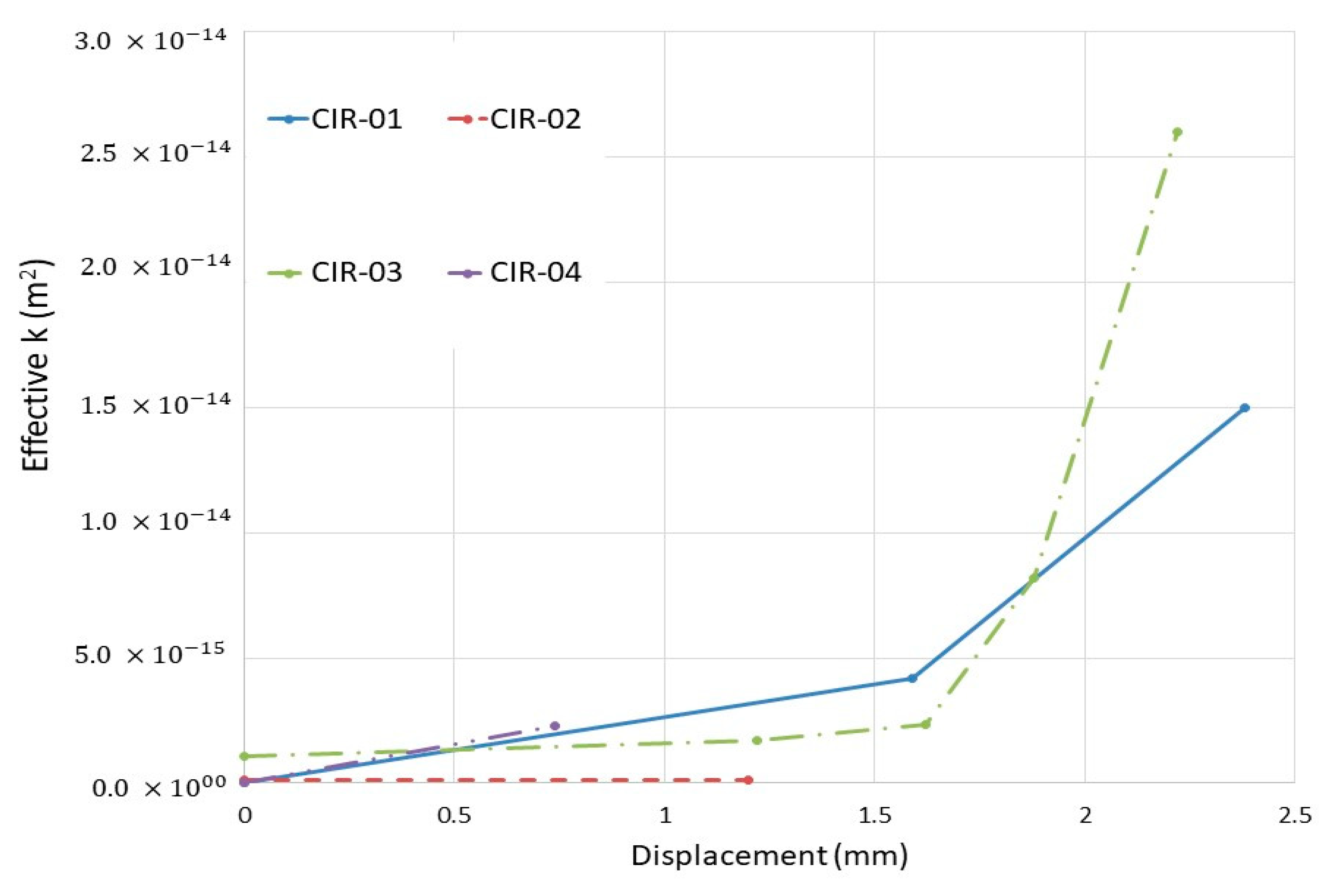
where, Po is the atmospheric pressure measured outside the tube, Pt is the pressure inside the tube at time t, h is the constant thickness of the tube, A is the surface area per unit length of the tube, k is the effective intrinsic permeability (m2), μ is the viscosity of the air (kg/m∙s), and C1 is a constant that can be defined considering the initial condition. The effective intrinsic permeability corresponding to each loading step determined for each structure using Equation (15) above is presented in Table 2. Figure 12 shows the vertical displacement corresponding to the loading step for each test structure and its relationship to the effective intrinsic air permeability. There were some deviations, but in general, the trends of increase in the effective intrinsic air permeability due to displacement were consistent among the structures. This study deals with the effect on the airtightness performance of the structure due to cracks that are generated from external loadings. Loading was the only factor considered for the generation of cracks in this study, which shows crack formation was directly related with the amount of load applied. Assuming that the cracks due to external loadings are closely related to the displacement, system airtightness could be described in terms of cracks in the structure. Therefore, considering the relationship between the displacement, or cracks of a structure and its corresponding air tightness, it will be possible to predict air tightness at the design stage of an SSTT system. A study of system airtightness in various loading conditions must follow for this. It should be noted that because there are inherent material and structural uncertainties in the concrete structures and difficulties in measuring cracks [14,15], computer-based crack analysis studies should be accompanied in parallel with the experimental and analytical approaches.

6. Conclusions

In this study, a correlation analysis was performed between the crack development in a concrete tube structure and the internal pressure change to evaluate the airtightness of an SSTT system. A differential equation that helps describe the behavior of the air flow into the concrete tube structure through the induced cracks was established by applying the Rizkalla leakage model. An analytical model was then developed to predict the internal pressure change of the SSTT system with time. The analyses with different inputs of crack-related parameters showed that system airtightness was highly sensitive to the cracks developed. In particular, the average crack width was found to have the greatest effect on the system airtightness. A crack index that can quantitatively express the generation of cracks was developed focusing on the correlation with the system airtightness. The developed crack index was found to be consistent with the input format of the Rizkalla leakage model. The analysis results of this study showed that it is essential to establish criteria for allowable cracks for the design of SSTT systems to ensure the airtightness performance, because the system airtightness is found to be highly sensitive to the degree of crack development.
An experimental test was carried out where the correlation between cracks and airtightness was indirectly investigated by observing the relationship between the airtightness and the displacement of concrete tube structures. The test result demonstrates the necessity of further crack analysis for evaluation of the airtightness performance of an SSTT system. It is suggested that computer-based crack analysis studies should be accompanied in parallel with the experimental and analytical approaches.

Author Contributions

Conceptualization, J.P.; methodology, P.D. and J.P.; validation, P.D. and J.P.; formal analysis, P.D. and J.P.; writing—original draft, P.D. and J.P.; supervision, J.P.; funding acquisition, J.P.

Funding

This research was funded by Wonkwang University in 2016.

Conflicts of Interest

The authors declare that there is no conflict of interests regarding the publication of this paper.

References

  1. Cassat, A.; Bourquin, V.; Mossi, M.; Badoux, M.; Vernez, D.; Jufer, M.; Macabrey, N.; Rossel, P. SWISSMETRO—0Project Development Status. In Proceedings of the International Symposium on Speed-up Service Technology for Railway and Maglev Systems (STECH’03), Tokyo, Japan, 19–22 August 2003; pp. 453–460. [Google Scholar]
  2. Park, J.; Kim, L.H.; Nam, S.W.; Yeo, I. Performance evaluation of airtightness in concrete tube structures for super-speed train systems. Mag. Concr. Res. 2013, 65, 535–545. [Google Scholar] [CrossRef]
  3. Park, C.H.; Cheon, D.S.; Park, J. Analytical model of fluid flow through closed structures for vacuum tube systems. Math. Probl. Eng. 2015, 2015, 210727. [Google Scholar] [CrossRef] [Green Version]
  4. Park, C.H.; Synn, J.H.; Park, J. Probabilistic performance assessment of airtightness in concrete tube structures. KSCE J. Civ. Eng. 2016, 20, 1443–1451. [Google Scholar] [CrossRef]
  5. Mehta, P.; Monteiro, P. Concrete: Microstructure, Properties, and Materials; McGraw-Hill: New York, NY, USA, 2005. [Google Scholar]
  6. KCI. Concrete Structure Standard; Ministry of Land, Transport and Maritime Affairs: Gyeonggi-do, Seoul, Korea, 2012.
  7. Park, J.; Cho, J.; Park, H.J. Probabilistic estimation of air-tightness of performance of concrete vacuum tube structures. In Proceedings of the 10th International Symposium on High Performance Concrete—Innovation & Utilization, Beijing, China, 16–18 September 2014. [Google Scholar]
  8. Soppe, T.E.; Hutchinson, T.C. Assessment of Gas Leakage Rates through Damaged Reinforced-Concrete Walls. J. Mater. Civ. Eng. 2012, 24, 560–567. [Google Scholar] [CrossRef]
  9. Rizkalla, S.H.; Lau, B.L.; Simmonds, S.H. Air leakage characteristics in reinforced concrete. J. Struct. Eng. 1984, 110, 1149–1162. [Google Scholar] [CrossRef] [Green Version]
  10. Suzuki, T.; Takiguchi, K.; Hotta, H. Leakage of gas through cracked concrete cracks. Nucl. Eng. Des. 1992, 133, 121–130. [Google Scholar] [CrossRef] [Green Version]
  11. Nagano, T.; Kowada, A.; Matumura, T.; Inada, Y.; Yajima, K. Experimental study of leakage through residual shear cracks on R/C walls. In Proceedings of the Structural Mechanics in Reactor Technology, Raleigh, NC, USA, 14–18 August 1989; pp. 139–144. [Google Scholar]
  12. Greiner, U.; Ramm, W. Air leakage characteristics in cracked concrete. Nucl. Eng. Des. 1995, 156, 167–172. [Google Scholar] [CrossRef] [Green Version]
  13. RPS Structure. Structural Requirements and Basic Design of Next Generation of Ultra-High Speed Transportation Tube System; Project Report; KICT: Ilsan, Korea, 2016. [Google Scholar]
  14. Ziari, A.; Kianoush, M.R. Investigation of flexural cracking and leakage in RC liquid containing structures. Eng. Struct. 2009, 31, 1056–1067. [Google Scholar] [CrossRef]
  15. Frosch, R.J. Another look at cracking and crack control in reinforced concrete. ACI Struct. J. 1999, 96, 437–442. [Google Scholar]
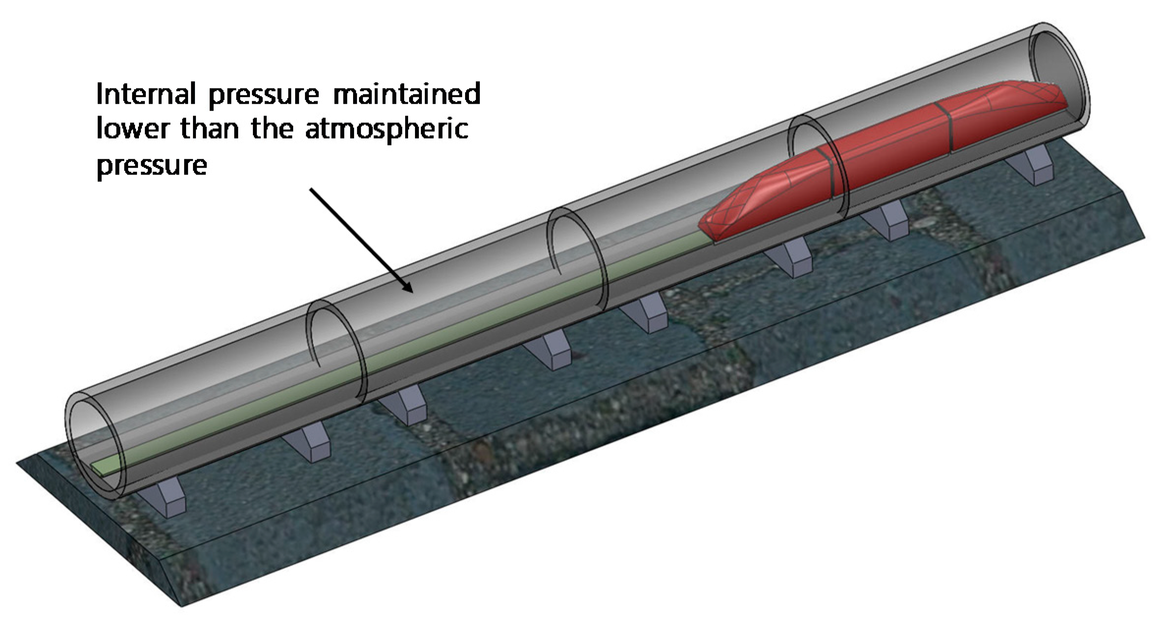
Figure 1. Concept of super-speed tube transport (SSTT) [2].
Infrastructures 04 00076 g001
Figure 2. Schematic of air flow into the tube structure through cracks.
Infrastructures 04 00076 g002
Figure 3. Simplified model for fluid flow through cracks.
Infrastructures 04 00076 g003
Figure 4. Dimensions of the proto-type structure.
Infrastructures 04 00076 g004
Figure 5. Increase in the internal pressure with time under different crack conditions (per unit length).
Infrastructures 04 00076 g005
Figure 6. Sensitivity of system air-tightness with respect to various crack parameters.
Infrastructures 04 00076 g006aInfrastructures 04 00076 g006b
Figure 7. Time required for the internal pressure to increase to 0.5 atm with respect to different crack parameters.
Infrastructures 04 00076 g007
Figure 8. Relationship between crack indices and tpr for Ppr = 0.1 atm.
Infrastructures 04 00076 g008aInfrastructures 04 00076 g008b
Figure 9. Relationship between crack indices and tpr for Ppr = 0.2 atm.
Infrastructures 04 00076 g009
Figure 10. Test configuration.
Infrastructures 04 00076 g010
Figure 11. Pressure change with time for test structures.
Infrastructures 04 00076 g011
Figure 12. Effective intrinsic air permeability vs. displacement.
Infrastructures 04 00076 g012
Table 1. Range of parameters for random combinations.
Control VariableMinimum ValueMaximum Value
B (m)0.10.7
N110
Wavg (m)0.00010.001
Table 2. Effective intrinsic air permeability corresponding to displacement of test structures.
Test Structure Load StepDisplacement (mm)
(Measured at Top of Tube Center)
Effective k (m2)
CIR-01Step 11.594.20 × 10 15
Step 22.381.50 × 10 14
CIR-02Step 11.201.05 × 10 16
CIR-03Step 11.221.70 × 10 15
Step 21.622.34 × 10 15
Step 31.888.20 × 10 15
Step 42.222.60 × 10 14
CIR-04Step 10.742.30 × 10 15