1. Introduction
Importance of energy consumption, in relation to environmental issues and the depletion of natural resources, has placed greater emphasis on promoting energy capture through other renewable resources. Solar power is perhaps the most prominent of all the renewable energies, according to the European Solar Thermal Industry Federation [
1]. That is why the analysis and evaluation of today’s solar thermal collector systems (hereafter STC) is so vital for revealing their limitations and studying improvements and innovations that enable their more widespread usage and the improvement of these aspects.
2. Requirements for the Design of a New STC
The issues regarding the architectural integration of collector elements are well known; as a result, they are nearly always relegated to rooftops where their presence goes unnoticed. This situation, therefore, requires an STC system capable of being integrated, architecturally, in building envelopes (Architectural integration refers to the capability of elements to fit aesthetically with or stand out positively from the other elements of a facade or rooftop). The new collector system must offer the possibility of aesthetically blending with and complementing the rest of the building envelope, and present a variety of finishes. The use of ceramic materials can play a major role in this respect.
The new collector system must meet criteria, in terms of energy and constructively. In constructive terms, the collector system must form part of the building envelope itself (facade and/or roof) and guarantee at least the same properties as the traditional building surface it is replacing. It must offer the possibility of being installed on the facade and/or roof without the need for an auxiliary substructure, using the substructure itself of the building envelope, thereby simplifying installation, offering the possibility of easily modifying the panel angle, guaranteeing a safe, fast, and simple implementation, favoring performance and enabling the straightforward replacement or removal of pieces if they are damaged or faulty.
By integrating the collector system in the building envelope, any part of the facade can be used to harness energy. Its architectural integration will allow it to be fitted onto large surface areas and, in turn, enable it to operate at lower temperatures than conventional systems. If we consider the Mediterranean climate, or other similar climates, it is sufficient to design a system that produces operating temperatures of between 30 °C and 60 °C.
A system is also required that is more viable economically for the final user and, so, the use of plates and metal conduits or special coatings that drive up the costs of the collecting system should be avoided. An STC should, therefore, be designed using lower cost materials, like ceramic, which today can replace metal in these applications. Along the same lines, to avoid emplacing the hermetic steel encasement on each collector (The hermetic metal encasement of conventional collectors, as well as being used as an open-pore waterproof and thermal insulating element, also serves, in some cases, as an element for attaching the collector to the auxiliary substructure.), it would be more suitable to use insulating, rigid-panel, closed-pore materials that are waterproof, and able to withstand high operating temperatures.
Lastly, the installation process must be easy, safe, and not require specialized workers, i.e., it should avoid anyone having to go out onto the facade.
3. Method and Materials
3.1. General Setup: Formats and Materials
Based on the aforementioned requirements, a ceramic building envelope system was designed comprising of two main elements: a ceramic collector panel with glass encasement and a ceramic non-collecting panel without glass (
Figure 1). This allows for a suitable combination of shiny surfaces (collector panels) and non-bright surfaces (non-collecting panels) which, in turn, can be combined aesthetically with the bright or reflective surfaces found on a building facade, such as windows, skylights etc.
For these panels, we propose two different formats to enhance the system’s versatility: the first, smaller one measures 1000 × 1000 mm, and the second is larger, measuring 1000 × 3000 mm. The large-format panel can be emplaced very quickly, and requires fewer connectors and joins on the casing. However, replacement parts are more expensive and auxiliary means are required for its correct handling and emplacement. The small-format panel is easier to install and can be more easily adapted to the window openings, but requires more connectors in proportion to the facade surface area it covers.
Once the general configuration of the new STC is established, an initial block of tests are undertaken, based mainly on the material choice and corresponding thicknesses. The thicknesses of the inner chambers are defined (the infrared trap and internal circuit for the flow of heat-transfer fluid), as well as that of the materials used for the collector panel itself (ceramic absorber plate, thermal insulation, and glass). Also, at the same time, through the construction of small prototypes, the energy performance of the collector is analyzed, as well as the system used to attach and install the panels on the facade.
3.1.1. Ceramic
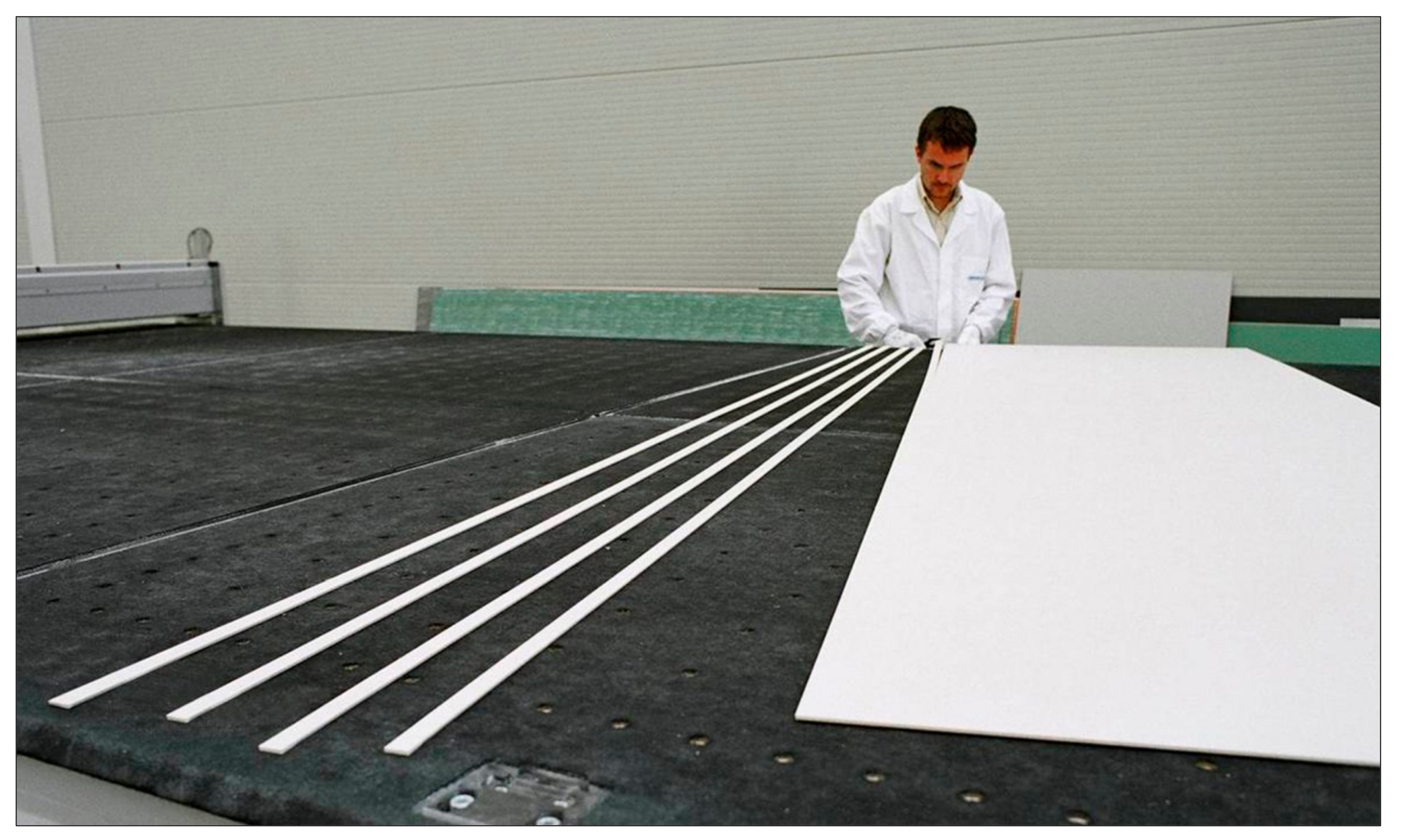
As has already been mentioned, ceramic plays a fundamental part in the design of this system. Therefore, it is necessary to use a product that is capable of adapting to the technical, architectural, and energy needs of the project. A thin porcelain slab with a large surface area, known commercially as Laminam (The product
Laminam was created in 2001 by the engineer Franco Stefani), meets the requirements. The format measures 1000 mm wide, 3000 mm long, and 3 mm thick, and offers a wide variety of finishes and colors both for offering an interesting architectural range and achieving efficient absorbencies in the darker colors [
3]. Due to its large surface area, floor-to-ceiling collector panels can be employed, and because of its reduced thickness, it is very lightweight (
Figure 2) and can be easily and accurately cut to create the interior partitions of the collector.
3.1.2. Glass
To improve the efficiency of the ceramic collector, a special high-transmission glass must be used (solar glass), which has a low FE203 content and is widely used in commercial collectors. Emplacing the collectors on the facade requires the use of glass laminates, and a thickness of 4 mm has been chosen to avoid excessive weight [
4].
3.1.3. Adhesive
The main challenge in this section was to find a type of adhesive that could join the base ceramic plate with the ceramic absorber plate and then the latter to the glass. There are, therefore, two join types: ceramic-ceramic and ceramic-glass.
The adhesive used to join the glass and the ceramic must be resistant to atmospheric agents and ultraviolet radiation, so that its performance is not deteriorated by such exposure. It must also resist the shear stress exerted by the weight of the glass laminate. To calculate the stress of the adhesive material used for this join, it will be put through a specifically designed simulation model, for which it is assumed that the adhesive layer has a thickness of 2 mm and width of 20 mm.
Furthermore, the adhesive used as a joining element between the absorber plate and base ceramic plate (ceramic-ceramic join) must be resistant to water and chlorine. It must also have resistance to high traction, as water circulates in the cavity between the two ceramic plates and the partition walls at a specific pressure. Likewise, the range of temperatures at which the adhesive maintains its properties must be considered, which has to include the operating temperature range of the collector, as this can, on occasion, reach relatively high temperatures (up to 100 °C). The adhesives supplied by companies that specialize in this kind of join (ceramic-ceramic) have been subjected to a laboratory-based tensile test. To this end, rectangular ceramic pieces measuring 20 × 65 mm were cut and stuck crosswise with each of the adhesives in question, with a join area of 20 × 20 mm. The pieces were left for three days to ensure that the adhesive had dried completely. Before the test was carried out, the pieces were submerged in a thermostatic bath of boiling water, i.e., at 100 °C, so that the join underwent the required temperature and humidity conditions.
3.1.4. Thermal Insulator
In this section, the vast majority of available thermal insulators in the building sector were analyzed. For each one, its resistance to water, capacity to provide the collector panel with rigidity, maximum operating temperature, thermal conductivity, and finally cost were analyzed (
Table 1).
Following this analysis, the material chosen to meet the aforementioned basic conditions is a rigid panel of polyisocyanurate (PIR). This is a mass-produced sandwich panel, formed by a core or center of rigid foam polyisocyanurate and two sides of paper with different finishes. It has many different formats, starting with 1220 mm wide and reaching up to 6000 mm in length. The thermal conductivity of this material is very low (around 0.026 W/mK), and it is capable of withstanding a maximum operating temperature of 120 °C. Furthermore, its market price falls within similar ranges to that of rockwool.
3.2. Testing Program
Once the different materials that comprise the new collector were chosen and analyzed, a series of tests were carried out to provide information regarding, among other aspects, the optimum distance between the glass laminate and the ceramic absorber plate (thickness of the infrared trap), the collector’s resistance to pressure, expansion, and water, compatibility between the materials, the type of internal circuit (series/parallel), the thickness, width, and separation of the internal ceramic partitions, the type of conduit, and the wiring system. For each of these tests, presented in the doctoral thesis of Roviras [
4] but, because of their length, not published in this article, the following parameters were determined:
The optimum thickness of the infrared trap was set at 10 mm.
Pressure testing on the collector defined a cavity width (distance between the internal walls through which the heat-transfer fluid will circulate) of maximum 50 mm. The expansion and waterproof tests showed that the prototypes, which were tested at different temperatures and pressures, did not present any leakages. Neither have been observed to have cracks due to thermal expansion.
The materials compatibility study, carried out through the analysis of the differential expansion rates between the materials that form the collector, verifies that the collector can easily withstand any sudden changes in temperature that it may be subjected to.
Regarding the type of internal circuit (through which the heat-transfer fluid will circulate), the collector, with the internal circuit in parallel, displayed a slightly superior performance to that of the collector with the circuit in series.
Of all the tubing studied, the models of cross-linked polyethylene (PEX) were considered the most suitable. An optimum diameter of the tubes was set at 12–13 mm.
3.3. Ceramic Solar Collector Type
To validate the configuration of the proposed ceramic collector panel, its energetic viability was tested in accordance with the applicable regulations on thermal solar energy collectors [
5]. In this test, a prototype measuring 1000 × 1000 mm was made using the materials and results obtained from the previous tests. To obtain the energy data, a specific experimental motorized device was used based largely on a thermostated bath, a membrane pump, a flowmeter, three thermoresistors, a pyranometer, and an anemometer (
Figure 3).
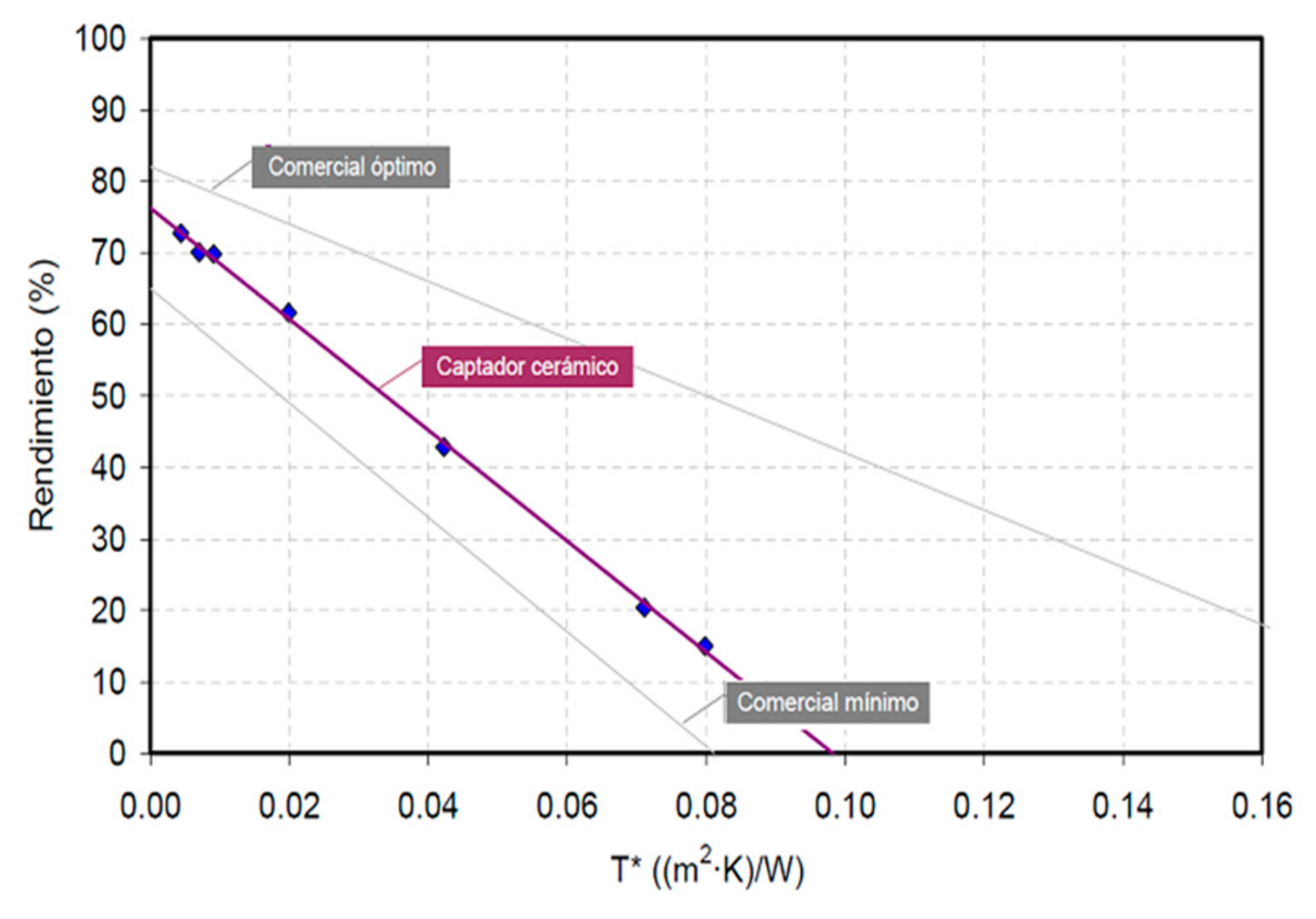
It is important to note that the characteristic curve of a STC (Solar Thermal Collector) (
Figure 4) is extracted from three parameters that provide information about its thermal operation. In first place is the optical efficiency (μ|
T* = 0): it is the value of the ordinate at the origin of the line and corresponds to the value of the collector’s performance when the parameter T* is equal to zero (Being T* the function of the water inlet temperature (Te), the ambient temperature (Ta) and solar radiation (Gs), by the following equation: T* = (Te−Ta)/Gs. Therefore, the determination of the characteristic curve consists of knowing the relation μ = μ (T*).). The inlet temperature of the water (Te) is equal to the ambient temperature (Ta). This is the maximum performance that can be obtained with a collector. The higher it is, the better the thermal behavior of the same. On the other hand, we have the global loss coefficient: this being the value of the slope of the characteristic curve and refers to the heat losses of the collector—the better isolated and designed, the smaller will be the value of this parameter. Finally, the temperature of stagnation (T*|
μ = 0): is the value of the parameter T* for the when the efficiency of the collector is zero, that is, the collector cannot raise the temperature of the water that is entering for given environmental conditions. The higher it is, the optical efficiency and/or lower is the global coefficient of losses, the greater the value of this parameter will be. Therefore, the energy efficiency of a collector will be higher, the higher its optical efficiency and lower its global coefficient of losses.
The parameters measured showed positive results. The graphs show a suitable relation between the solar radiation and the collector’s water outlet temperature (
Table 2), which reaches a maximum of 32 °C, enough for the sought-after performance (We should remember that for an STC such as the one proposed, in a Mediterranean climate and with an architectural integration that would allow it to be emplaced on large surface areas, there is the possibility of operating at temperatures that are lower than those of conventional systems and, therefore, temperatures no lower than 30 °C would be sufficient). With the data from the tests, the characteristic curve of the tested ceramic collector was determined, and compared together with the curves of other commercial collectors, one of optimum performance and the other with minimal characteristics: the curve of the proposed collector falls within the normal performance range of commercial collectors (
Figure 5). In any case, it must be taken into account that the optimum collector considered (conventional CST) uses metallic materials in its construction (better thermal conductor than ceramics), special and selective coatings that have a high absorptivity of solar radiation and that reduce the losses of the collector. The data obtained with the ceramic collector are reasonably good considering the materials used and the large area available (the entire facade), as it is an integrated system that is part of the external enclosure system of a building [
6,
7].
3.4. Proposal for the Design of the Constructive System
Alongside the aforementioned tests, the design of the constructive system was also studied for the installation of the ceramic collector casing that, to achieve full architectural integration, must form part of the building envelope itself [
8,
9], and respond to the improvements outlined in the introduction of this article: simple and fast to install, safe for the operator to assemble, easy to disassemble the panels individually and, preferably, the possibility to assemble from inside the building.
As well as these aspects, it is also worth adding that the constructive system must be capable of absorbing possible structural movements, acting independently of the inner skin to avoid the existence of acoustic bridges, and offer a final thickness for the facade surface (collector casing + support + internal finish) of no more than 30 cm, to remain competitive in today’s market. Under these premises, a constructive system has been developed with a total of five different metal profiles, three of which are in formats that exist on the market today (found in basic catalogues of metal profiles). This last factor has very favorable repercussions on the final cost of the system [
10].
Below are 8 steps to follow for installing the building envelope (
Figure 6):
Step 1: Vertical Alignment of the Perimeter Angled Profile
This first step develops from an already constructed pillar-and-slab structure, and consists of positioning the perimeter l-profile, aligned with the plumb defined for the construction. This profile will be anchored to the slab using screws, and the slots in the profile itself, to adapt the alignment of the structure to the plumb line. All this is done from inside the building. Thereafter, the de-solarized panel is put in position, passing it over the perimeter l-profile, ready to receive the self-levelling mortar which will serve as a base for the floor finish. The vertical crease of the perimeter l-profile also acts as a retaining element for the regulating layer in this case.
Step 2: Attachment of Upright Profiles
The next step is to fix the Ω-100 sheet steel upright profiles to the perimeter l-profile in the slab. The uprights are held in place through the wings of the omega profile and using specific screws. The total height of this profile is variable, depending on the height between building slabs. The top of the uprights is aligned to a specific height and laser-controlled, to ensure uniform positioning of all profiles. They are set at approximately 70 cm above the slab level, which is already regulated, ensuring a comfortable and safe position for the person connecting the profiles. The remaining profile length, reaching up to 3 m, approximately, will always be connected below to the lower profile by way of a connecting piece. This operation is also carried out from inside the building.
Step 3: Connection between Uprights
Afterwards, the upright profiles (Ω-100) are connected through a connecting element which is also an omega section. This connector is fitted in complete safety and comfort from inside the building, and ensures the connection between uprights, besides acting as a regulating element for the height difference that can be found between building slabs. The join is done using specific screws through the slotted holes in the connecting profile.
Step 4: Fixing the Horizontal Slide Rails
Once all uprights are secured and connected, the metal slide rails are fixed, that will serve as guides for the collector and non-collecting panels. Their sizing and location will depend on the modulation established according to the format of the panels.
Step 5: Attaching the Anchor Points
Attached to the uprights using screws are the pieces that anchor and retain the panels. This fixing system comes from the GLACTIS research project, with reference number DEX-530000-2008-91 obtained a financing of the Spanish State through the Ministry of Industry, Tourism and Commerce and was also developed together with the Universitat Internacional de Catalunya (UIC), Uralita Iberia and the ceramic materials company Saloni.
Steps 6 and 7: Fixing and Connection of Panels
The emplacement of the panels follows the sequence shown in
Figure 7: first insert the panel in the upper horizontal groove, and swing inwards until it inserts into the lower guide. The panel is then slid along this lower guide until it meets its neighboring section, the panel now being held alone between the horizontal slide rails. The panels are then fixed to the anchor points prepared on the uprights.
Lastly, the tubes of the collector panels are installed and connected, all from inside the building.
This assembly sequence allows for an easy and quick disassembly of panels, should they need servicing, repairing, or if one has broken, without the need to interfere with or handle the adjacent panels. For this reason, the cross-section of the panel had to be studied, and a minimum thickness be set for the horizontal joins that allow the panel movements necessary for the panel to be removed.
Step 8: Internal Partition Wall
Once the collector panels have been fully connected, the internal section is completed using any of the systems on the market for industrialized partitions of laminated plasterboard and steel profiles.
The design allows the system to offer a dual functionality, both energy-related and constructive, guaranteeing the same requirements and thicknesses (no greater than 26 cm) as a conventional envelope, only including, within the same thickness, an integrated solar collector.
4. Construction of Prototypes and Real Test
Lastly, a set of prototypes, four collector panels, and two non-collecting panels were assembled (
Figure 8), with the aim of building a portion of the facade to assess their energy performance, technical-constructive feasibility, and architectural integration (This field test was carried out on the roof of the ITC laboratory in Castellón (Spain). It should be noted that the area of Castellón enjoys conditions that are typical of the Mediterranean climate, with high levels of solar radiation throughout the year).
With collectors in place on the metal substructure, the correct fit of the different pieces and good performance of the system, in general, was closely observed. The surface angle of the collectors was virtually perfect, and no significant misalignments were detected between them.
To determine the efficiency of the ceramic solar collectors, a specific experimental assembly was used. The evolution of some of the parameters obtained (ambient temperature, solar radiation, and temperature of inlet and outlet water), during a typical sunny February day, are of particular interest, and verify the collector’s correct performance when receiving sunlight.
At the end of the energy tests and after 18 months had passed since the installation of the prototype facade, the correct performance of the anchoring system was verified, no defects or noticeable problems were detected, and both the collector panels and non-collecting panels were in good condition (
Figure 9).
5. Conclusions
It has been proven that it is feasible to implement a thermal collector envelope using ceramic materials that comply with the initial feasibility conditions and that contemplate the following results:
5.1. Architectural Integration
The proposed thermal collector envelope offers the possibility of aesthetic combinations and a variety of finishes. The variety of finishes that ceramic offers (color and texture) allows the envelope to adapt to any requirements regarding architectural design [
11]. The designed system allows for an interplay between the reflections and luster of the glass panels, and the dull surfaces of the ceramic panels. The proposed system, therefore, has sufficient resources to integrate architecturally.
An envelope has been successfully created that, on the one hand, resolves the building envelope and, on the other, is able to capture the sun’s energy and use it for hot water and/or heating. Moreover, the anchoring of the panels is carried out using a single construction system, and avoids the use of auxiliary substructures. Therefore, the new ceramic collector system performs well with regard to both constructive criteria and energy performance [
12].
5.2. Economic Benefits
A solar thermal collector, constructed using ceramic materials, has been successfully developed. These materials have replaced metals and their corresponding selective coatings. Furthermore, the ceramic collectors form part of a thermal collector envelope that replaces the conventional envelope, eliminates the added cost of conventional collectors on the market, and avoids the use of auxiliary structures for anchoring purposes. Furthermore, by using PEX tubing, there is no need for metallic elements on the collector panels’ distribution and connection system. Therefore, the final cost of the system and its corresponding depreciation is reduced to a minimum.
The total thickness of the collector panel is 51 mm (26 mm without the thermal insulation), which is approximately 30–35% less thick than a conventional flat-plate collector. Also, if one considers that this thickness is part of the building envelope, unlike most thermal collectors on the market that are attached onto the building envelope, it can be concluded that the system proposed here is highly competitive, as it favors a greater useful area and reduces the constructed surface area [
13].
5.3. Constructive System of the Building Envelope
The prototype facade was built by workers with no previous experience in facade and/or roof construction. The clarity of the construction system enabled its correct implementation, thereby demonstrating its simplicity of installation and ensuring a straightforward, safe construction. The field tests also showed the ease with which a panel can be removed without needing to interfere with adjacent panels.
The field test demonstrated the correct structural performance of the proposed anchoring system, when subjected to the permanent loads generated by the weight of the panels and metal profiles, and variable loads caused by the wind.
5.4. Suitability for the Mediterranean Climate
The laboratory and field tests carried out on the different prototypes, validate the thermal yields obtained achieving operating temperatures of between 30 °C and 45 °C. Therefore, when considering its application on large surface areas and in areas with a high level of solar radiation, this is a successful design for a ceramic thermal collector envelope with a performance that suits the Mediterranean climate.


