Article

Adaptive Nonlinear Control and State Estimation for Energy Management in Standalone Photovoltaic–Battery Systems


by
Nabil Elaadouli
1,
Ilyass El Myasse
2,
Abdelmounime El Magri
1,
Rachid Lajouad
1,
Mishari Metab Almalki
3,* and
Mahmoud A. Mossa
4,*
1
Electrical Engineering and Intelligent Systems Laboratory, Higher Normal School of Technical Education Mohammedia, Hassan II University of Casablanca, Mohammedia 28830, Morocco
2
Laboratory of Engineering Sciences and Biosciences, Faculty of Sciences and Technologies of Mohammedia, Hassan II University of Casablanca, Mohammedia 28830, Morocco
3
Department of Electrical Engineering, Faculty of Engineering, Al-Baha University, Alaqiq 65779-7738, Saudi Arabia
4
Electrical Engineering Department, Faculty of Engineering, Minia University, Minia P.O. Box 61111, Egypt
*
Authors to whom correspondence should be addressed.
Inventions 2026, 11(3), 49; https://doi.org/10.3390/inventions11030049
Submission received: 31 March 2026 / Revised: 23 April 2026 / Accepted: 8 May 2026 / Published: 18 May 2026

Abstract

This paper presents an adaptive nonlinear control and state observation framework for energy management in standalone photovoltaic (PV) systems integrated with battery energy storage. A unified nonlinear dynamic model is developed to describe the interactions between the PV generator, the DC/DC buck converter, and the lithium-ion battery. Based on this model, a multi-mode control strategy is designed to ensure efficient and safe operation under varying environmental and loading conditions. The proposed scheme incorporates maximum power point tracking (MPPT) to maximize photovoltaic energy extraction, along with constant current (CC) and constant voltage (CV) charging modes to guarantee battery safety and longevity. To address uncertainties and unmeasured states, an adaptive nonlinear observer is developed for real-time estimation of the battery open-circuit voltage and state of charge. The observer design is supported by Lyapunov-based stability analysis, ensuring boundedness and convergence of the estimation error in the presence of modeling uncertainties and external disturbances. An energy management algorithm is further introduced to coordinate the transition between operating modes according to the estimated system states and battery constraints. The effectiveness and robustness of the proposed control and observation strategy are validated through detailed simulations in MATLAB/Simulink under varying solar irradiance conditions. The results demonstrate accurate maximum power tracking, reliable state estimation, and safe battery charging performance, highlighting the potential of the proposed approach for advanced autonomous PV–battery systems.

1. Introduction

The rising demand for clean, reliable, and distributed energy solutions has boosted the development of autonomous solar energy systems. Photovoltaic (PV) technology has emerged as one of the most attractive renewable energy sources due to its environmental friendliness and continuously reducing installation costs [1]. Hence, solar-based systems are progressively adopted in a large variety applications, in particular electric vehicle charging stations (EVCS), standalone power systems, and remote infrastructures [2,3].
Standalone PV systems depend on local energy generation and storage to provide a continuous and reliable supply. By contrast, the electrical power generated by the PV system is intrinsically intermittent and reliant on environmental conditions, specifically solar irradiance and temperature [4,5]. This fact makes immediate use of solar energy unsuitable in several applications, given that the generated power cannot satisfy the instantaneous load demand. To mitigate this limitation, battery energy storage systems (BESS) are frequently integrated with PV sources [6,7]. Considering the available storage technologies, lithium-ion batteries are extensively adopted due to their high energy density, long lifetime, and high efficiency [8,9,10].
In a typical standalone PV system, a power electronic converter is crucial to adjust the PV electrical characteristics to meet the battery charging requirements [11,12]. Specifically, the DC/DC buck converter is widely used to regulate the PV output voltage and provide a safe and efficient battery charging process [13,14]. The overall proposed system, consisting of a PV generator, a DC/DC buck converter, and a lithium-ion battery, thereby represents a fundamental architecture for standalone solar applications.
However, the dynamic behavior of such systems is coupled and strongly nonlinear. The current-voltage relationship of the PV generator is nonlinear [15,16], the DC/DC buck converter introduces nonlinear averaged dynamics [17], and the lithium-ion battery presents complex electrochemical behavior [18]. Combined with external disturbances and parameter uncertainties, these nonlinearities make the control of the proposed system a challenging task. Most existing works rely on conventional linear control approaches, such as proportional–integral (PI) controllers, whose performance often degrades under nonlinear and uncertain operating conditions [19,20,21].
Several control strategies have been reported in the literature for photovoltaic battery charging applications. For instance, intelligent MPPT approaches based on adaptive neuro-fuzzy inference systems (ANFIS) have been proposed to improve maximum power extraction under varying environmental conditions, including partial shading and mismatch conditions, with enhanced tracking accuracy and dynamic response [22]. In parallel, other works have investigated PV-based battery charging architectures using alternative converter topologies and auxiliary storage arrangements to ensure continuous charging operation under both sunshine and non-sunshine conditions, with experimental validation under laboratory operation [23]. These studies confirm the importance of advanced control design in improving charging efficiency, robustness, and operating flexibility. However, most existing works mainly focus either on MPPT enhancement or on system-level charging functionality, while less attention is given to the unified integration of nonlinear control, battery charging mode regulation, and state observation within a single control-oriented framework.
Along with control challenges, accurate information of the battery state of charge (SOC) is crucial for the reliable operation of standalone PV systems. The SOC is not directly accessible and must therefore be estimated using mathematical models and electrical measurements [24,25]. Conventional SOC estimation techniques, such as coulomb counting, are affected by cumulative errors and measurement noise, which significantly reduce their accuracy over long-term operation [26]. To mitigate these issues, this paper proposes a framework for next-generation standalone PV systems based on nonlinear control and adaptive battery state observation. The proposed system consists of a photovoltaic generator, a DC/DC buck converter, and a lithium-ion battery. A unified nonlinear model is developed to describe the system dynamics, and nonlinear control laws are designed to regulate the charging process under different operating modes, including maximum power point tracking (MPPT) to maximize the extracted photovoltaic power under varying solar conditions, constant current charging (CC), and constant voltage charging (CV) to protect the battery against overcurrent and overvoltage [27]. An energy management algorithm is therefore developed to automatically select the most appropriate operating mode. Furthermore, an adaptive nonlinear observer is introduced to estimate the battery state of charge, with stability guarantees provided by Lyapunov-based analysis. The effectiveness of the proposed approach is validated through numerical simulations under MATLAB/Simulink R2024a. This work is structured as follows. Section 2.1 is dedicated to the modeling of the PV-based charging system. Section 2.2 presents the proposed nonlinear approach. The energy management strategy is described in Section 2.3. Section 2.4 focuses on the adaptive observer developed for SOC estimation. The simulation results and discussion is illustrated in Section 3. Section 5 concludes the paper.

2. Materials and Methods

2.1. System Modeling

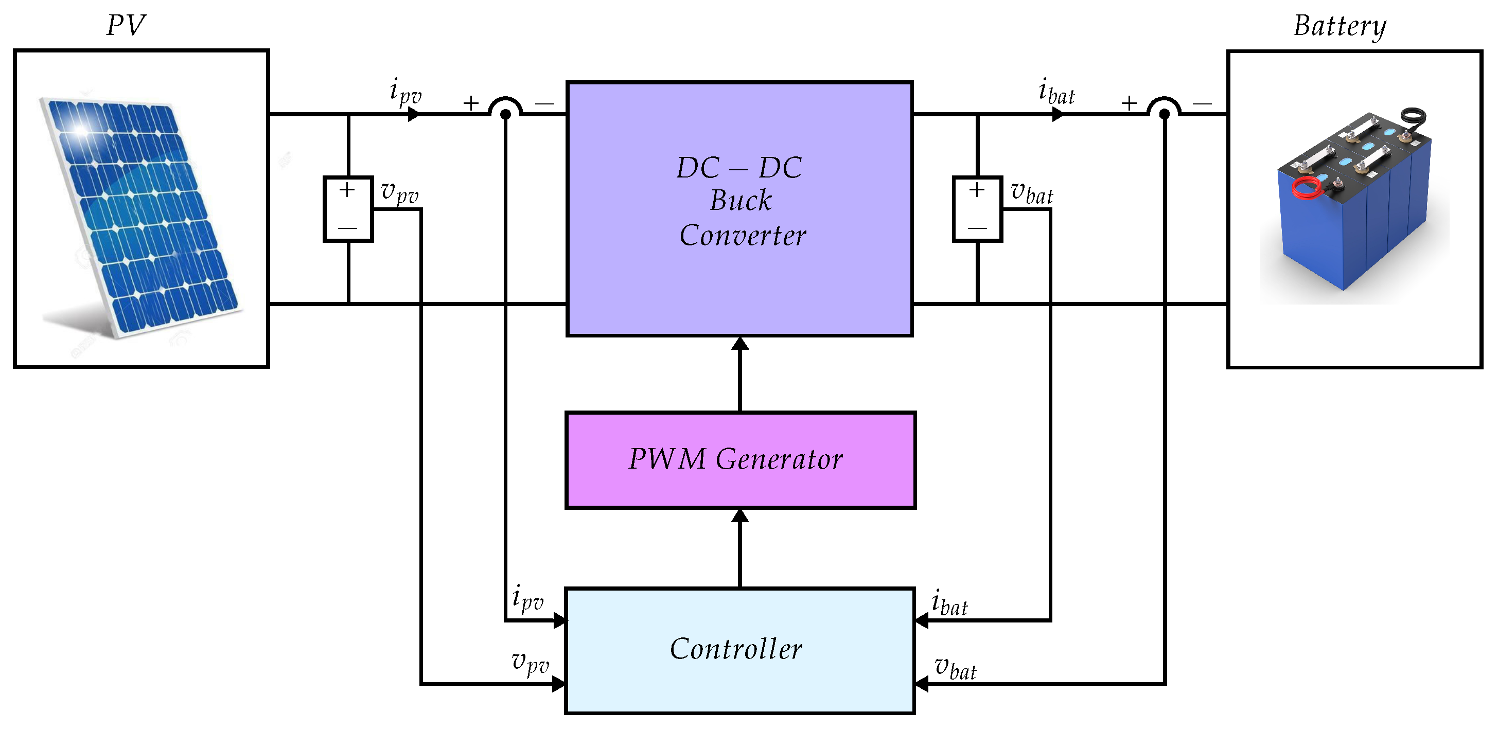
As shown in Figure 1, the proposed standalone photovoltaic–battery charging system consists of a PV generator, a DC/DC buck converter, a PWM generator, a nonlinear controller, and a lithium-ion battery.

2.1.1. Photovoltaic Panel Modeling

The photovoltaic (PV) generator is described using the classical single-diode model, which accurately captures its nonlinear current–voltage behavior. Accordingly, the output current of the PV module is expressed as
I = I p h I s exp q ( V + I R s ) a K T N s 1 V + I R s R p ,
where I p h denotes the photocurrent, I s is the diode reverse saturation current, q is the electron charge, K is the Boltzmann constant, T is the cell temperature, N s is the number of series-connected cells, R s and R p are the series and shunt resistances, respectively, and a is the diode ideality factor. The photocurrent is directly dependent on solar irradiance and may be written as
I p h = I p h , r e f + K i ( T T r e f ) G G r e f ,
where G is the solar irradiance, G r e f is the reference irradiance, I p h , r e f is the photocurrent under reference conditions, K i is the temperature coefficient of the current, and  T r e f is the reference temperature. In addition, the reverse saturation current is temperature dependent and is given by
I s = I r r T T r exp E G 0 γ K 1 T r 1 T ,
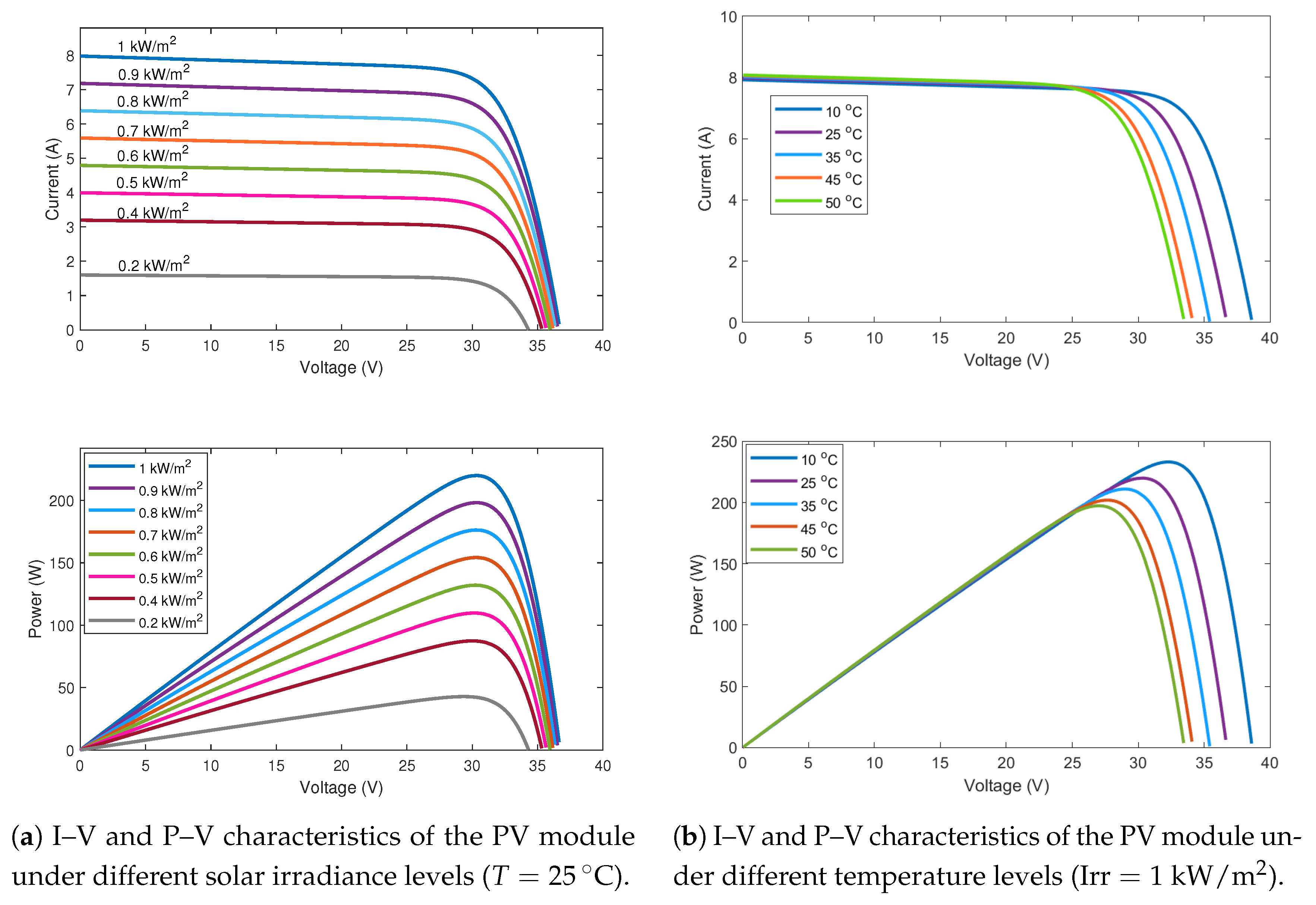
where I r r is the reverse saturation current at the reference temperature T r , E G 0 is the semiconductor band-gap energy, and  γ is a technology-dependent constant. These expressions show that the solar irradiance affects the PV output current explicitly through the photocurrent term, thereby influencing the overall electrical characteristics of the PV generator. Figure 2 shows the I–V and P–V characteristics of the PV module under different solar irradiance and temperature conditions.

2.1.2. DC/DC Buck Converter Modeling

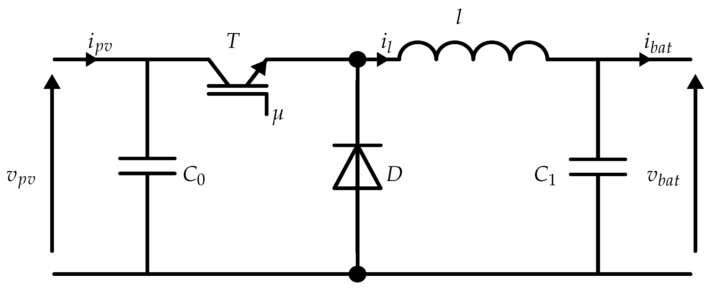
The DC/DC buck converter is utilized to step down the PV voltage to a suitable level for battery charging thereby guaranteeing high conversion efficiency. As illustrated in Figure 3, the converter is composed of a controlled switch T, a diode D, an input and output capacitor C 0 and C 1 respectively, and an inductance l [28,29].
During operation, the converter alternates between two switching states corresponding to the ON and OFF positions of the power switch.
Mode 1 (Switch ON; μ = 1 ): In this mode, the transistor is turned on, resulting in a zero voltage drop across the switch, while the diode remains blocked. The PV generator supplies energy to both the inductance and the output stage. The dynamic behavior of the system is governed by the following state equations:
d v p v d t = 1 C 0 ( i p v i l )
d i l d t = 1 l ( v p v v b a t )
d v b a t d t = 1 C 1 ( i l i b a t )
Mode 2 (Switch OFF; μ = 0 ): When the transistor is turned off, the diode becomes forward-biased, ensuring a freewheeling path for the inductance current, while the switch blocks the input source. In this configuration, the inductance releases its stored energy to the load, and the system dynamics are described by the following equations:
d v p v d t = 1 C 0 i p v
d i l d t = 1 l v b a t
d v b a t d t = 1 C 1 ( i l i b a t )
The average state-space model of the DC-DC buck converter can be expressed as:
d v p v d t = 1 C 0 i p v μ i l
d i l d t = 1 l μ v p v v b a t
d v b a t d t = 1 C 1 i l i b a t
where i l denotes the inductance current and i b a t is the battery current. This averaged model provides a convenient framework for the design of advanced control strategies aimed at regulating the battery charging process.

2.1.3. Battery System Modeling

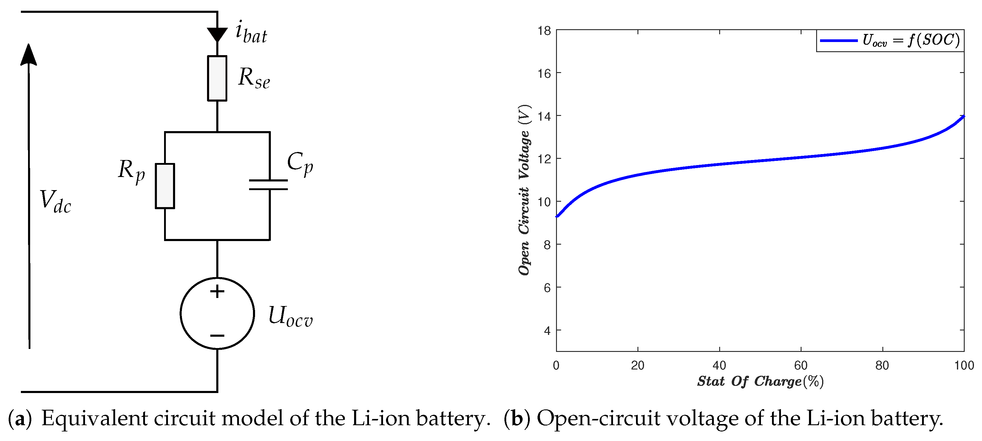
The battery is modeled using a first-order equivalent circuit model composed of an open-circuit voltage source U o c v , a series internal resistance R s e , and a parallel R C network formed by the polarization resistance R p and capacitance C p . This model captures both the instantaneous voltage drop due to internal hmic losses and the transient voltage dynamics associated with electrochemical polarization effects [30,31]. The open-circuit voltage U o c v is considered as a nonlinear function of the state of charge (SOC) [32], as illustrated in Figure 4b.
U o c v = f ( S O C ) = γ 0 + γ 1 S O C + γ 2 S O C 2 + + γ q S O C q + + γ n S O C n
The polynomial approximation of the OCV–SOC characteristic was obtained from the manufacturer-provided data under nominal operating conditions using an offline polynomial curve-fitting procedure. More precisely, the OCV values corresponding to different SOC levels were extracted from the battery datasheet and approximated by a polynomial function, whose coefficients were then used in the proposed model.
The coefficients ( γ 1 , , n ) are presented in Table 1. The stat equation of the Li-ion battery is given by:
d v p d t = v b a t R s e C p U o c v R s e C p R s e + R p C p R p R s e v p
and
i b a t = v b a t v p U o c v R s e
Remark 1. 
The polynomial approximation (13) is derived from manufacturer data under nominal operating conditions. This choice is adopted to obtain a control-oriented representation suitable for nonlinear controller and observer design. Therefore, the proposed formulation is not intended to capture all battery phenomena, such as temperature, ageing, or parameter drift with high fidelity. Instead, these effects are regarded here as bounded uncertainties, while the present study focuses on establishing the feasibility and stability of the proposed nonlinear control and estimation framework.

2.1.4. The Overall System’s Model

The overall dynamic behavior of the proposed charging station is described by a unified nonlinear state-space model, obtained by interconnecting the individual subsystems, namely, the PV generator, the DC/DC buck converter, and the battery storage unit, and is expressed by the following system of equations:  
x ˙ 1 = 1 C 0 i p v μ x 2
x ˙ 2 = 1 l μ x 1 x 3
x ˙ 3 = 1 C 1 x 2 i b a t
x ˙ 4 = a x 3 a U o c v b x 4
where x 1 , x 2 , x 3 and x 4 denote, respectively, the averages values of v p v , i l , v b a t and v p . and:  
a = 1 C p R s
b = 1 C p R p + 1 C P R s

2.2. Controller Design Method

This section is devoted to the synthesis of the control laws associated with the different operating modes of the proposed system. Specifically, three main modes are considered, namely the Maximum Power Point Tracking (MPPT) mode, the Constant Current (CC) charging mode, and the Constant Voltage (CV) charging mode. For each mode, an appropriate nonlinear controller is designed in order to ensure accurate reference tracking, fast dynamic response, and robustness against system uncertainties and external disturbances.

2.2.1. Control Objectives

The following control objectives (CO1, CO2 and CO3) are defined to outline the multi-objective control framework adopted in this study.
CO1. MPPT control objective: In the Maximum Power Point Tracking (MPPT) mode, the main control objective is to maximize the power extracted from the photovoltaic generator by forcing its operating point to track the maximum power point under varying environmental conditions. This is achieved by regulating the PV terminal voltage ( v p v ) to follow the optimal reference ( v p v o p t ) generated by the modified INC algorithm. The MPPT controller is therefore designed to ensure fast convergence toward the optimal operating point, while minimizing steady-state oscillations and maintaining robustness against irradiance and temperature variations.
CO2. Constant voltage (CV) charging mode: In the constant voltage (CV) charging mode, the main control objective is to maintain the battery terminal voltage at its nominal reference value ( v b r e f ) when the battery is fully charged. This mode ensures that the charging process is completed smoothly without overvoltage, which could degrade battery performance or compromise safety. The CV controller is therefore designed to accurately regulate the battery voltage while gradually reducing the charging current as the state of charge increases.
CO3. Constant current (CC) charging mode: In the constant current (CC) charging mode, the control objective consists in regulating the battery charging current ( i b a t ) to a predefined reference value ( i b r e f ) in order to guarantee safe and efficient energy storage. This mode is particularly activated when the battery charging current exceeds its maximum allowable value. The CC controller aims at preventing excessive current stress on the battery cells, thereby reducing thermal effects and extending the battery lifetime.

2.2.2. The Proposed MPPT Algorithm

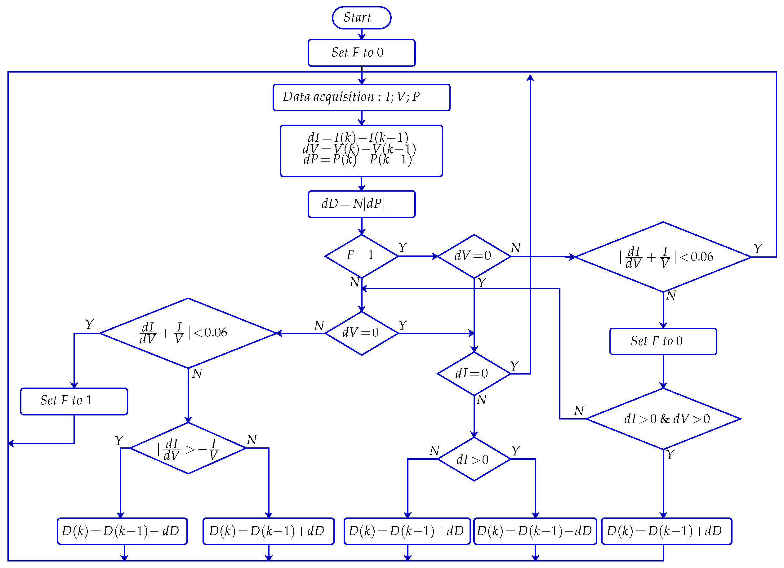
The proposed MPPT strategy, as depicted in Figure 5, is based on a modified Incremental Conductance (INC) algorithm that combines a variable step size mechanism with an adaptive decision logic to improve tracking performance under fast irradiance variations. At each sampling instant, the photovoltaic voltage and current are measured, and the corresponding power is calculated. The incremental quantities Δ I , Δ V , and  Δ P are then computed, and the duty cycle variation is adaptively adjusted according to:
Δ D = N Δ P
where N is a positive scaling factor. This variable step size allows faster convergence during transients while ensuring reduced oscillations around the steady-state operating point.
In contrast to the conventional I N C algorithm, which relies on a strict equality condition ( d I d V = I V ) to detect the maximum power point (MPP), the proposed method introduces a permissible error band defined by
d I d V + I V < ε ,
with ε = 0.06 . This tolerance improves numerical robustness and enables reliable MPP detection despite measurement noise and discretization effects.
Furthermore, a memory flag F is incorporated to store the MPP detection state. When the system operates within the tolerance band, the flag is set to one, indicating that the MPP has been reached. If the operating point subsequently leaves this region and simultaneous increases in both current and voltage are detected ( Δ I > 0 and Δ V > 0 ), which is a signature of a sudden irradiance rise, the algorithm applies a corrective action by increasing the duty cycle instead of following the conventional INC decision [33]. This mechanism prevents incorrect tracking directions typically observed in classical INC under fast irradiance changes.
Consequently, compared with the standard INC approach, the proposed algorithm exhibits three main improvements: (i) an adaptive step size ensuring faster dynamic response and reduced steady-state oscillations, (ii) a tolerance-based MPP detection enhancing numerical stability, and (iii) an irradiance variation detection logic allowing correct decision-making under rapidly changing environmental conditions. These features significantly enhance the overall MPPT performance and robustness of the photovoltaic system.

2.2.3. The MPPT Controller Design

In the M P P T operating mode, the control objective is to force the PV terminal voltage ( x 1 = v p v ) to track its optimal reference provided by the MPPT algorithm ( x 1 * = v p v o p t ). Based on the averaged PV-side dynamics in (16) and the Backstepping approach, the first tracking error is defined as
e 1 = x 1 x 1 *
Taking the time derivative and using Equation (16a) yields
e ˙ 1 = x ˙ 1 x ˙ 1 * = 1 C 0 i p v μ x 2 x ˙ 1 *
where μ denotes the duty ratio and x 2 = i l is the inductance current. Following the backstepping procedure, a stabilizing first-step dynamics is imposed by selecting
e ˙ 1 = c 1 e 1
with c 1 > 0 . This requirement leads to the desired virtual control condition μ and, equivalently, to the control law:
μ m p p t = 1 x 2 i p v + C 0 c 1 e 1 C 0 x ˙ 1 *
which guarantees exponential convergence of the PV-voltage tracking error. Moreover, since μ explicitly depends on x 2 , the inductance-current dynamics (16b) ensures consistent energy transfer between the PV side and the battery side (through x 3 = v b a t ), while the remaining subsystem ((16c) and (16d)) describes the battery electrical behavior and the polarization voltage evolution used for SOC-related monitoring and charging management.
The inductor current of x 2 is assumed to be strictly positive regardless of t during normal operation, which is guaranteed by the continuous conduction mode and the energy management strategy employed.

2.2.4. The CV Charging Controller Design

In the constant-voltage (CV) charging mode, the control objective is to regulate the battery terminal voltage ( x 3 = v b a t ) to a prescribed reference ( x 3 * = v b r e f ). Based on the averaged battery-side dynamics (16c), the voltage tracking error is defined as:
e 2 = x 3 x 3 *
By differentiating e 3 and using (16c), one obtains:
e ˙ 2 = x ˙ 3 x ˙ 3 * = 1 C 1 x 2 i b a t x ˙ 3 *
where x 2 = i l denotes the inductance current. In the Backstepping framework, α 1 = x 2 is treated as a virtual control input for the x 3 -subsystem, and a stabilizing error dynamics is imposed as
e ˙ 2 = c 2 e 2
with c 2 > 0 . Hence, the desired virtual control (reference inductor current) is selected as:
α 1 * = i b a t + C 1 x ˙ 3 * C 1 c 2 e 3
Defining the second error variable e 3 = α 1 α 1 * and using (16b), the inductance-current error dynamics can be written as follows:
e ˙ 3 = x ˙ 2 α 1 * = 1 l μ x 1 x 3 x ˙ 2 *
Finally, choosing the duty ratio μ as:
μ C V = 1 x 1 x 3 + l x ˙ 2 * l c 3 e 3
with c 2 > 0 , yields e ˙ 3 = c 3 e 3 and ensures the exponential convergence of both e 2 and e 3 . Consequently, the proposed CV controller guarantees accurate regulation of the battery voltage to x 3 * , while naturally enforcing a smooth reduction of the charging current as the battery approaches full charge.

2.2.5. The CC Charging Controller Design

In the constant-current (CC) charging mode, the control objective is to regulate the battery current to its reference value ( i b a t = i b r e f ). To this end, the first tracking error is defined as:
e 4 = i b a t i b a t *
Considering the battery electrical model, the polarization voltage dynamics (16d) and the capacitor relation (16c), the derivative of e 4 can be expressed as:
e ˙ 4 = 1 R s e 1 C 1 x 2 i b a t a x 3 + a U o c v + b x 4 = c 4 e 4
where c 4 > 0 is a design gain. Following the backstepping philosophy, the inductance current x 2 is treated as a virtual input and denoted by α 2 = x 2 . Enforcing the stabilizing dynamics e ˙ 4 = c 4 e 4 yields the desired virtual control α 2 * as:
α 2 * = C 1 a x 3 a U o c v b x 4 c 4 R s e e 4 + i b a t
Next, the second error variable is introduced to ensure the tracking of the virtual input:
e 5 = α 2 α 2 * = x 2 α 2 *
Using the inductor dynamics (16b), the error dynamics of e 5 is given by:
e ˙ 5 = x ˙ 2 α ˙ 2 * = 1 l μ h 1 h 3 α ˙ 2 *
By imposing the stable first-order behavior e ˙ 5 = c 5 e 5 with c 5 > 0 , the duty ratio is finally obtained as:
μ C C = 1 x 1 x 3 l c 5 e 5 + α ˙ 2 * .
With the above two-step design, the closed-loop errors e 4 and e 5 converge exponentially to zero, which guarantees accurate regulation of the battery charging current in CC mode while ensuring a smooth power transfer through the DC-DC conversion stage.

2.3. Energies Management System

The control framework developed in Section 2.2 is structured in a modular manner, enabling decoupled tuning and a clear delineation of responsibilities among the individual control loops. Nevertheless, effective coordination of power exchanges among the different subsystems requires the introduction of a supervisory control layer operating at a higher hierarchical level.
The proposed energy management system (EMS), represented by Algorithm 1, supervises the DC-DC conversion stage by selecting one of three operating modes according to the battery charging constraints. Under normal conditions, the photovoltaic generator operates in maximum power point tracking (MPPT) mode, where the PV voltage is regulated to its optimal reference to maximize the harvested energy. When the battery becomes fully charged ( S O C S O C max ), the EMS switches to the constant-voltage (CV) mode to maintain the battery terminal voltage at its rated value and prevent overvoltage. In addition, battery protection is enforced through a constant-current (CC) mode: whenever the measured charging current exceeds the maximum allowable limit ( i b a t > I b max ), the EMS activates CC operation and forces the charging current to track the saturated reference I b max . This hierarchical rule-based logic ensures safe battery charging while preserving high energy extraction from the PV source.
Algorithm 1 Battery charging mode selection algorithm
1:
Initialize the system
2:
Measure i b a t , i b r e f , and  S O C
3:
if  S O C < 100 %  then
4:
   if  i b a t < i b m a x  then
5:
     Activate the MPPT-based charging mode
6:
   else
7:
     Activate the constant-current ( C C ) charging mode
8:
   end if
9:
else
10:
   Activate the constant-voltage ( C V ) charging mode
11:
end if
Remark 2. 
The proposed battery charging algorithm is designed as a supervisory mechanism that selects the appropriate charging mode according to the battery state and operating constraints. In the present study, its function is restricted to coordinating transitions between the MPPT, CC, and CV modes, while the stability of each mode is ensured separately by the corresponding nonlinear controller. Hence, the proposed switching logic should be understood as a control-oriented coordination strategy within the considered operating framework.

2.4. Adaptive SOC Observer Method

To achieve an accurate estimation of the battery state of charge (SOC) under parameter uncertainties and unmodeled dynamics, an adaptive observer is introduced. Owing to the fact that the open-circuit voltage U o c v cannot be directly measured and exhibits slow variations compared with the electrical variables, it is regarded as an unknown time-varying quantity to be identified online. The observer relies on the correction of the voltage estimation error through adaptive update laws, which ensure convergence of the estimation process and improve robustness against external disturbances and parameter variations.

2.4.1. Dynamic Model of the Battery

The battery behavior is described using a reduced-order electrical representation that captures the terminal voltage dynamics, internal polarization effects, and the slowly varying open-circuit voltage. This formulation is derived from the governing relationships expressed in (12), (14) and (15), which collectively characterize the interaction between the electrical variables and the electrochemical equilibrium voltage. The open-circuit voltage U o c v is assumed to vary slowly over time and is affected by bounded nonlinear dynamic. This representation provides an appropriate basis for observer design and state-of-charge estimation while maintaining low computational complexity.
Accordingly, the battery dynamics can be expressed as:
v ˙ b a t = λ 1 v b a t + λ 1 v p + λ 1 U o c v + 1 C 1 i b a t v ˙ p = λ 2 v p + λ 3 U o c v + λ 3 v b a t U ˙ o c v = ξ ( t ) ,
where the parameters λ 1 , λ 2 , and λ 3 are defined as
λ 1 = 1 R s e C q ,   λ 2 = R s e R p C p R p R s e ,   λ 3 = 1 C p R s e ,
and ξ ( t ) denotes an unknown but bounded disturbance satisfying | ξ ( t ) | < ε 0 .

2.4.2. Compact State-Space Formulation

For control and observer design purposes, the battery dynamics can be rewritten in a compact state-space form. Let the state vector, input, and output be defined as
χ = v b a t v p U o c v = χ 1 χ 2 χ 3 ,   y = v b a t
Accordingly, the battery dynamic equations can be expressed as
χ ˙ ( t ) = A χ ( t ) + Φ ( h ( x , i l , t ) , χ 1 ) + D   ξ ( t ) ,
with the output equation
y ( t ) = C χ ( t ) .
The system matrices are given explicitly by
A = λ 1 λ 1 λ 1 λ 3 λ 2 λ 3 0 0 0 ,   Φ ( h ( x , i l , t ) , χ 1 ) = h ( x , i l , t ) λ 3 χ 1 0 ,   C = 1 0 0 ,
and
D = 0 0 1 ,
where ξ ( t ) represents an unknown but bounded disturbance associated with the slow evolution of the open-circuit voltage, satisfying | ξ ( t ) | < ε 0 .
The parameters λ 1 , λ 2 , and λ 3 are defined as
λ 1 = 1 R s e C q ,   λ 2 = R s e R p C p R p R s e ,   λ 3 = 1 C p R s e .

2.4.3. Observer Design

Once the open-circuit voltage has been accurately estimated, the battery state of charge is subsequently determined via the reconstructed U o c v by exploiting the nonlinear O C V S O C mapping. Specifically, the SOC is obtained by inverting this characteristic according to
S O C ^ = f 1 ( U ^ o c v ) = β n U ^ o c v   n + β n 1 U ^ o c v   n 1 + + β 1 U ^ o c v + β 0 ,
where β i (Table 2) are the coefficients of the polynomial function f 1 ( x ) . This indirect estimation strategy relies on the electrochemical equilibrium voltage rather than direct current integration, thereby significantly reducing the drift effects typically associated with pure coulomb-counting methods. As a result, accurate and stable S O C tracking is achieved, making the proposed approach well suited for real-time battery management and energy management system applications. Motivated by the results reported in [34], the development of the adaptive nonlinear observer is formalized through the following theorem.
Theorem 1. 
Consider the battery system described by (37), where the open-circuit voltage dynamics are affected by an unknown bounded disturbance ξ ( t ) satisfying | ξ ( t ) | ε 0
  • Let the adaptive observer be defined as:
    χ ^ ˙ = A χ ^ + Φ ( h ( x , i l , t ) , χ 1 ) + L C χ χ ^ y ^ = C χ ^
    where L R 3 is the observer gain matrix, A and C are given in (40). If the gain matrix L is chosen such that the matrix ( A L C ) is Hurwitz, then the system (46) constitutes a valid adaptive observer for the battery dynamics.
  • For any real constant r satisfying r > r 0 , the estimation error e ( t ) = χ ^ χ is globally convergent, independently of the initial condition e ( t 0 ) , and satisfies the following inequality:
    e ( t ) λ max λ min   e ( t 0 )   e r r 0 2 λ min ( t t 0 ) + 2 λ max ε 0 r r 0 1 e r r 0 2 λ min ( t t 0 ) ,
    where λ m i n and λ min are defined in the proof of Theorem 1. As a consequence, the observation error e ( t ) converges, independently of the initial conditions, to a bounded region characterized by a sphere of radius 2 λ max ξ 0 r r 0 . Moreover, this residual bound can be made arbitrarily small by choosing a sufficiently large value of r.
Proof. 
Define the observation error as
e ( t ) = χ ^ ( t ) χ ( t ) .
Combining the battery dynamics (40) with the observer Equation (46) yields the following error dynamics:
e ˙ ( t ) = ( A L C ) e ( t ) + Φ h ( x , i l , t ) , χ 1 Φ h ( x , i l , t ) , χ ^ 1 D   ξ ( t ) .
Since the pair ( A , C ) is observable, the gain matrix L can be selected such that ( A L C ) is Hurwitz. Therefore, for any r > 0 , there exists a symmetric positive definite matrix P satisfying the Lyapunov equation
( A L C ) P + P ( A L C ) = r I 3 .
Consider the Lyapunov candidate function
V ( e ) = e P e .
Differentiating (51) along (49) gives
V ˙   = 2 e P e ˙   = 2 e P ( A L C ) e + 2 e P Φ ( h , χ 1 ) Φ ( h , χ ^ 1 ) 2 e P D   ξ ( t ) .
Using (50), the linear term can be rewritten as
2 e P ( A L C ) e   = e P ( A L C ) + ( A L C ) P e   = r e 2 .
Assume that Φ ( · ) is Lipschitz with respect to its second argument, i.e.,
Φ ( h , χ 1 ) Φ ( h , χ ^ 1 ) d e ,
for some constant d > 0 , and that the disturbance is bounded as
| ξ ( t ) | ε 0 .
Let λ max and λ min denote the maximum and minimum eigenvalues of P, respectively. By applying the Cauchy–Schwarz inequality to (52) and using (54) and (55), one obtains
V ˙   r e 2 + 2 λ max d e 2 + 2 λ max D ε 0 e .
In this work, D = [ 0     0     1 ] (see the compact form in (40)), hence D = 1 and (56) reduces to
V ˙ r e 2 + 2 λ max d e 2 + 2 λ max ε 0 e .
Define
r 0 = 2 λ max d .
Then, (57) can be rewritten as
V ˙ ( r r 0 ) e 2 + 2 λ max ε 0 e .
Since P 0 , the following bounds hold:
λ min e 2 V λ max e 2 .
From (60), it follows that
e 2 V λ max ,   e V λ min .
Using (61) into (59) yields
V ˙ r r 0 λ max   V + 2 λ max ε 0 λ min   V .
Let W ( t ) = V ( t ) . For W > 0 , W ˙ = V ˙ 2 V = V ˙ 2 W , hence (62) implies
W ˙ r r 0 2 λ max   W + λ max ε 0 λ min .
For any r > r 0 , solving the linear comparison system associated with (63) gives
W ( t ) W ( t 0 ) e r r 0 2 λ max ( t t 0 ) + 2 λ max 2 ε 0 ( r r 0 ) λ min 1 e r r 0 2 λ max ( t t 0 ) .
Finally, using W = V together with (60), the estimation error satisfies
e ( t ) λ max λ min   e ( t 0 )   e r r 0 2 λ min ( t t 0 ) + 2 λ max ε 0 r r 0 1 e r r 0 2 λ min ( t t 0 ) ,
which concludes the proof. □

3. Results

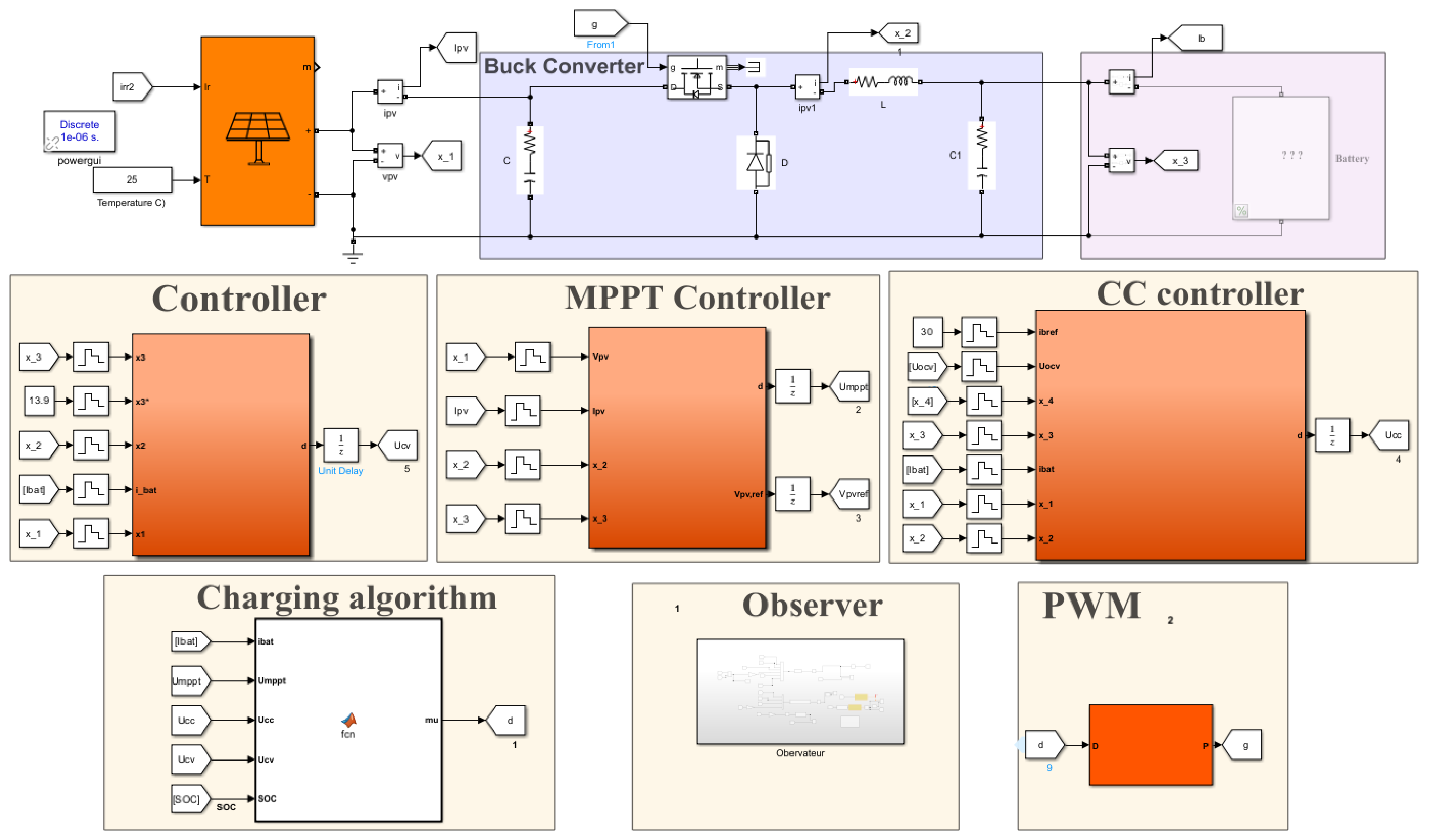
The performance of the proposed control strategy and the adaptive observer is tested through numerical simulations under MATLAB/Simulink environment (Figure 6). The system dynamics are implemented using the nonlinear model derived in Section 2.1, while the control input defined in (24), (30) and (36) are used to regulate the charging process under the different operating modes. The adaptive observer described in Section 2.4 is also implemented to estimate the battery SOC. The electrical parameters of the PV module, the lithium-ion battery, and the DC/DC buck converter are given by Table 3, as well as the controller gains, are summarized in Table 4. The following simulation scenarios are used to confirm the effectiveness of the proposed nonlinear control strategy, energy management system, and adaptive observer under solar irradiance variation.

3.1. The Control Strategy Performances

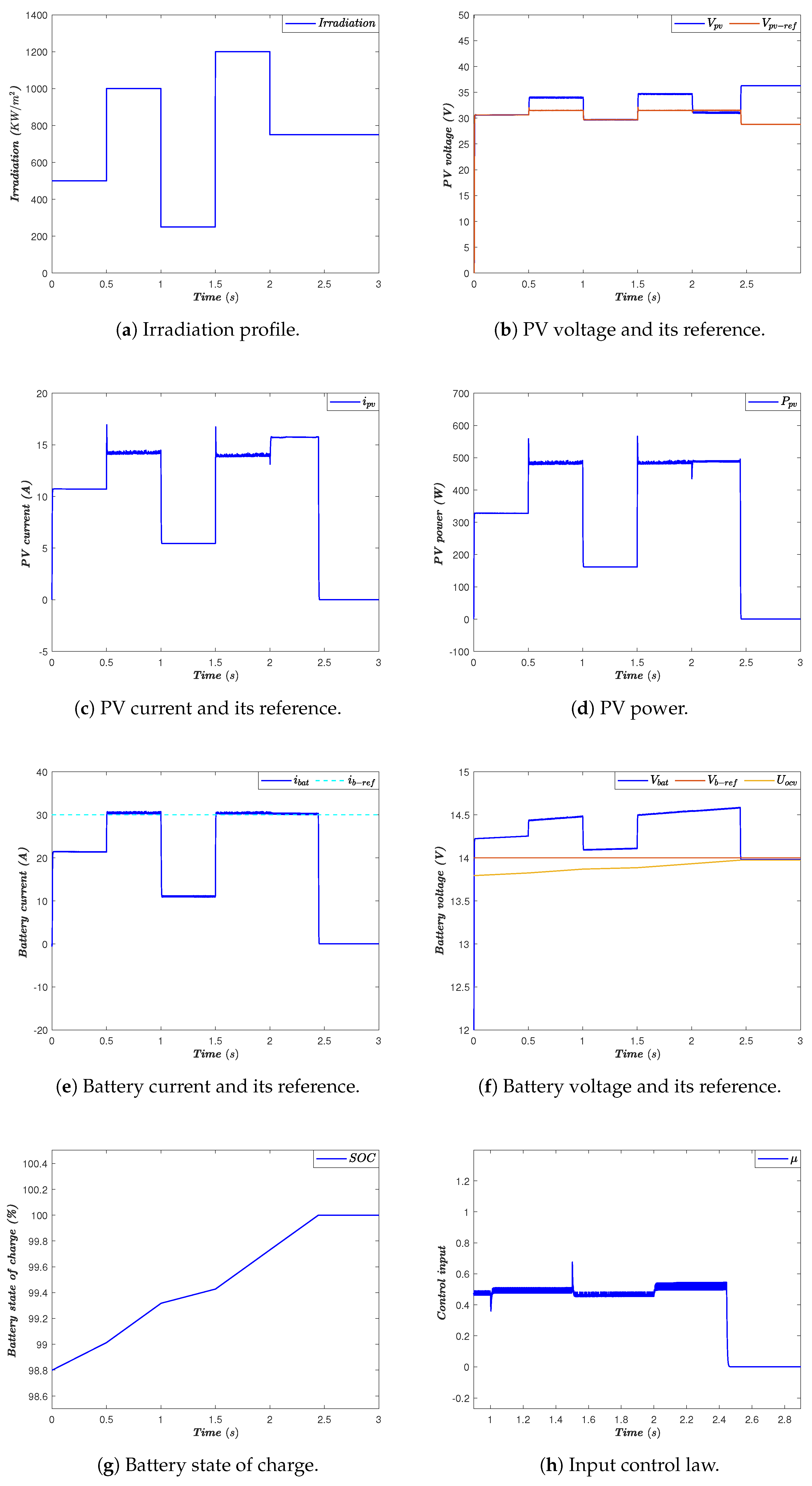
The first simulation scenario (Figure 7) examines the battery charging process under a stepwise irradiation profile, as shown in Figure 7a. Initially, the battery is not fully charged ( S O C < 100 % ), the energy management algorithm selects the MPPT operating mode. During this phase, the PV voltage V p v tracks its optimal reference V p v o p t as depicted in Figure 7b, allowing maximum power extraction from the PV generator. The battery current increases progressively, and the SOC shown in Figure 7g rises accordingly.
At t = 0.5 s, a sudden increase in solar irradiation induces the battery charging current i b a t to exceed its admissible limit i b m a x = 30 A as illustrated in Figure 7e, the energy management algorithm switches from MPPT mode to constant current (CC) mode in order to prevent battery overcurrent. The battery charging current is then regulated and limited to its maximum value, ensuring safe charging process.
At t = 1   s , the irradiation level decreases, which reduces the available PV power. Therefore, the algorithm returns to MPPT mode, allowing the system to continue extracting the maximum available solar power while the battery continues to charge. A similar behavior occurs around t = 1.5 s, where the irradiation increase leads again to the activation of the CC mode to maintain the battery current within its safe limit.
As the charging process progresses, the battery S O C gradually approaches its maximum value ( S O C = 100 % ), as shown in Figure 7g. At approximately t = 2.45 s, the battery becomes fully charged and the energy management algorithm switches to constant voltage (CV) mode. During this phase, the battery voltage is regulated around its reference value ( V b r e f = 14 V), as illustrated in Figure 7f, preventing overvoltage and ensuring safe charging termination.
Overall, the simulation results corroborate that the proposed control and energy management strategy coordinated operation between MPPT, CC, and CV operating modes. The transitions between modes are smooth, the battery current and voltage remain within their safety limits, and the state of charge evolves consistently during the charging process. These results validate the robustness and effectiveness of the proposed approach under rapid solar irradiance variations.
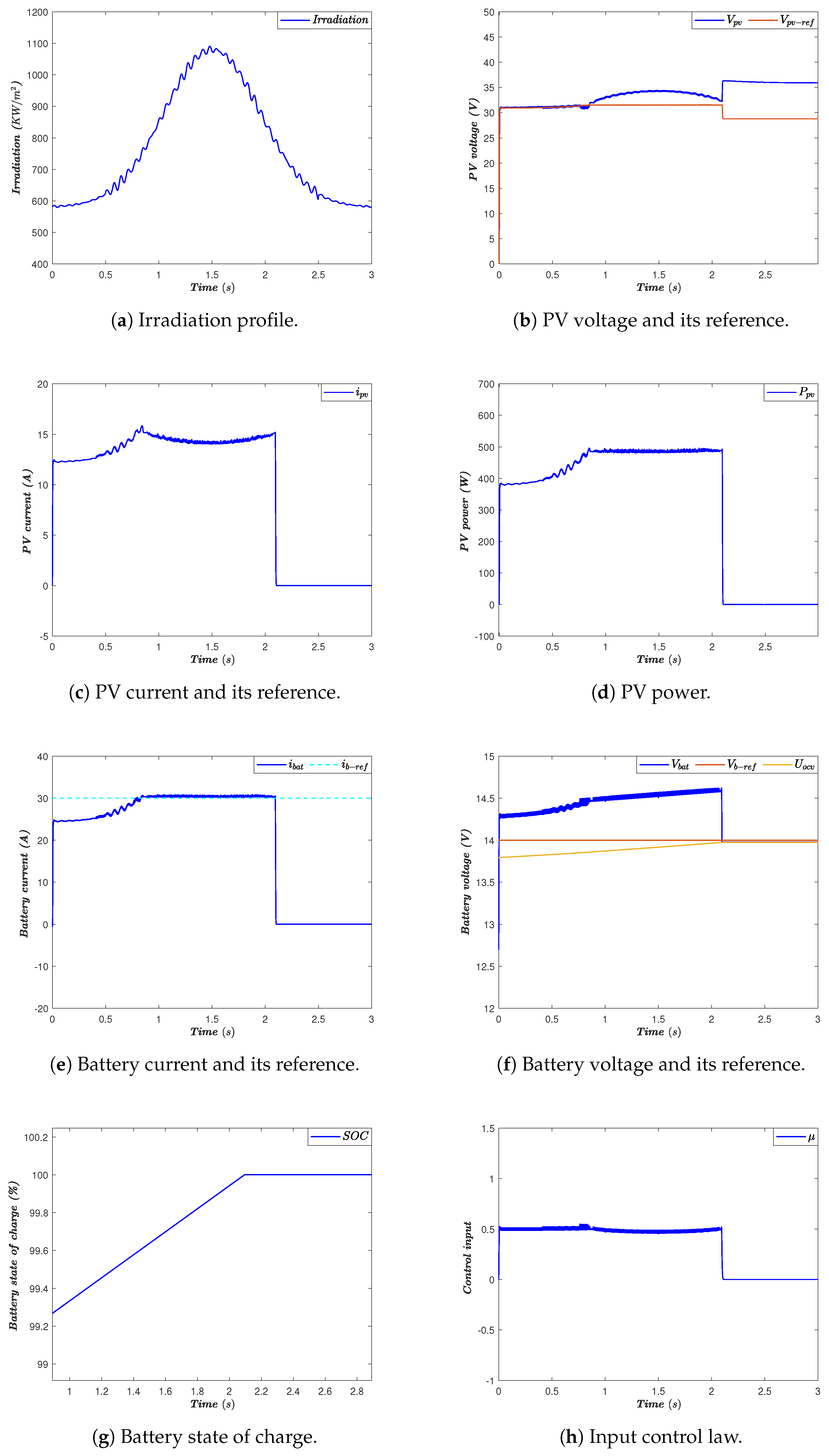
The second simulation scenario depicted bye Figure 8 examines the performance of the proposed control and energy management strategy under a smoothly varying solar irradiation profile, as illustrated in Figure 8a. Unlike the previous stepwise profile, the irradiation varies continuously over time, simulating real operating conditions. Despite these variations, the proposed control strategy ensures stable operation of the PV charging system.
Figure 8b shows that the photovoltaic voltage V p v continues to track its reference V p v o p t generated by the M P P T algorithm, providing efficient photovoltaic power extraction. The corresponding PV current ( i p v ) and power ( P p v ) illustrated in Figure 8c,d follow the solar irradiation variation, validating the correct operation of the MPPT controller under gradual solar variations.
The battery charging behavior is represented in Figure 8e,f. The battery current i b a t is regulated around its reference value ( i b r e f = 30 A) during the constant current (CC) mode, ensuring safe charging process. At the same time, the battery voltage v b a t increases gradually toward its reference value v b r e f = 14 V, thereby reflecting the normal charging operation. As depicted in Figure 8g, the battery state of charge increases smoothly until reaching its maximum value ( S O C = 100 % ).
Once the battery reaches full charged, the energy management algorithm switches to constant voltage (CV) mode, keeping the battery voltage around its nominal value ( v b r e f = 14 V). The control input represented by Figure 8h remains bounded with smooth dynamic throughout the simulation, which validates the stability and robustness of the proposed nonlinear control strategy.
Overall, these results confirm that the proposed control, energy management, and observation framework operates effectively not only under abrupt solar irradiation changes but also under realistic continuous solar variations.

3.2. The Observer Performances

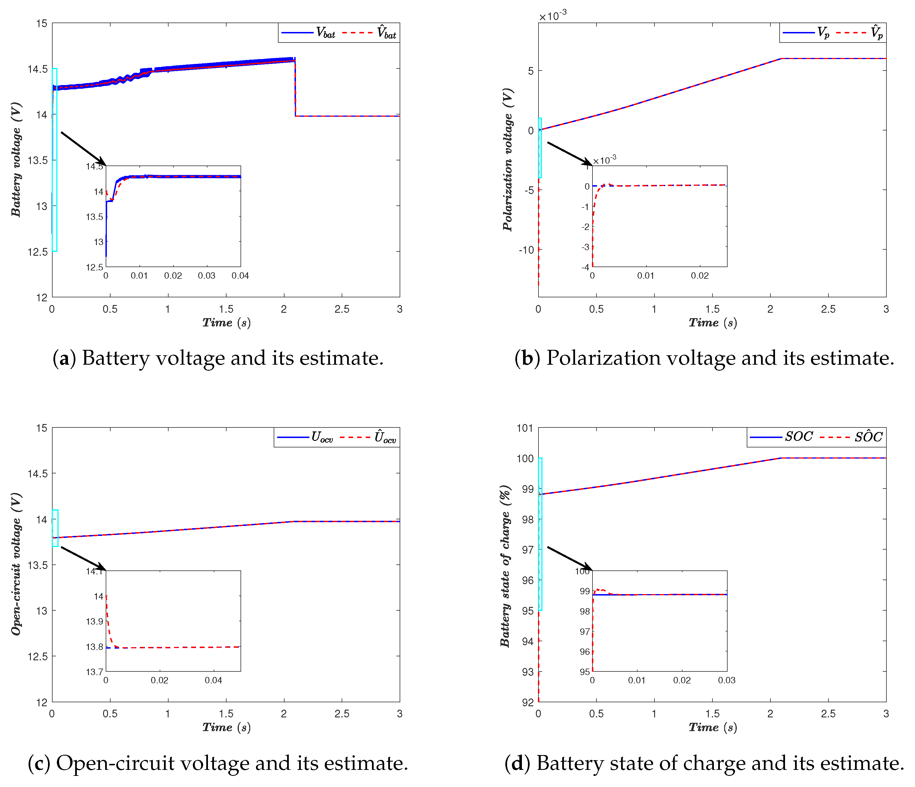
The proposed adaptive observer’s performance is shown in Figure 9, where the estimated states are compared with their true values. Figure 9a–d represent the estimation of the battery voltage ( v ^ b a t ), the polarization voltage ( v ^ p ), and the open-circuit voltage ( U ^ o c v ), respectively. In each cases, the estimated variables rapidly converge toward their true values after a short transient phase.
The zoomed regions included in the figures represent the observation error during the initial instants of the simulation. These enlarged views demonstrate that the estimation errors decrease quickly and remain negligible in steady-state operation, confirming the fast convergence and accuracy of the proposed observer.
Figure 9d depicts the estimation of the battery state of charge. The estimated ( S O C ^ ) closely tracks the actual S O C trajectory throughout the simulation. The small estimation error observed in the zoomed region confirms the effectiveness of the adaptive observer in reconstructing the battery internal states.
Overall, the observer achieves accurate estimation of the battery voltage, polarization voltage, open-circuit voltage, and S O C , even in the presence of solar irradiance variations. These results confirm the convergence properties predicted by the Lyapunov-based stability analysis and validate the suitability of the proposed observer for real-time battery monitoring and energy management applications.

4. Discussion

The simulation results demonstrate the effectiveness of the proposed nonlinear control and energy management strategy for standalone photovoltaic–battery systems. Under both stepwise and smooth irradiance variations, the PV voltage accurately tracks its optimal reference, confirming the ability of the MPPT controller to maintain efficient energy extraction despite changes in solar conditions. The battery current and voltage remain within their predefined safety limits, which validates the proper coordination between MPPT, constant-current, and constant-voltage charging modes. In particular, the transition from MPPT to CC mode prevents excessive charging current, while the transition to CV mode ensures safe charging termination when the battery approaches full charge. Moreover, the adaptive observer provides accurate estimation of the battery voltage, polarization voltage, open-circuit voltage, and state of charge, with fast convergence and low steady-state error. These results confirm that the proposed framework improves charging safety, enhances energy utilization, and provides reliable state monitoring. Nevertheless, the present validation is based on numerical simulations, and future work should include experimental implementation to further assess the robustness of the proposed strategy under real operating conditions, including temperature variations, battery aging, and measurement noise.

5. Conclusions

This paper presented a nonlinear control and adaptive observation framework for standalone PV battery charging systems. The suggested architecture, consisting of a photovoltaic generator, a DC/DC buck converter, and a lithium-ion battery, was modeled using a unified nonlinear representation describing the dynamic coupling between the energy source, the power electronic interface, and the storage unit.
To guarantee safe and efficient battery charging process, three operating modes were considered, namely maximum power point tracking (MPPT), constant current (CC), and constant voltage (CV). An energy management algorithm was designed to select the appropriate operating mode according to the system conditions and battery constraints. This strategy allows maximum photovoltaic power extraction while ensuring the battery protection against overcurrent and overvoltage.
In addition, an adaptive nonlinear observer was developed to estimate the battery open-circuit voltage and the state of charge. The observer design was supported by Lyapunov-based stability analysis, ensuring convergence of the estimation error toward a bounded region.
The simulation results obtained for different irradiation profiles validate the effectiveness and robustness of the proposed approach. The nonlinear controller ensured accurate photovoltaic voltage tracking, smooth transitions between operating modes, and safe battery charging behavior. Moreover, the observer provided accurate estimation of the internal battery states, confirming the theoretical analysis.

Author Contributions

Conceptualization, N.E., A.E.M. and M.A.M.; Formal analysis, I.E.M., R.L. and A.E.M.; Data curation, I.E.M. and R.L.; Software, N.E., I.E.M. and R.L.; Visualization, R.L., I.E.M. and M.A.M.; Writing—original draft, N.E., I.E.M. and R.L.; Validation, I.E.M., R.L. and M.M.A.; Investigation, I.E.M., R.L. and M.M.A.; Methodology, I.E.M., R.L. and N.E.; Resources, M.M.A. and A.E.M.; Writing—review and editing, M.A.M., M.M.A. and N.E. All authors have read and agreed to the published version of the manuscript.

Funding

This research received no external funding.

Data Availability Statement

Data are available upon request from the corresponding author.

Conflicts of Interest

The authors declare no conflicts of interest.

References

  1. El Mezdi, K.; El Magri, A.; Watil, A.; El Myasse, I.; Bahatti, L. Integrated control and energy flow management for hybrid grid-connected photovoltaic/wind systems with battery storage using fuzzy logic controllers. IFAC-PapersOnline 2024, 58, 442–447. [Google Scholar] [CrossRef] [Scilit]
  2. Dada, M.; Popoola, P. Recent advances in solar photovoltaic materials and systems for energy storage applications: A review. Beni-Suef Univ. J. Basic Appl. Sci. 2023, 12, 66. [Google Scholar] [CrossRef] [Scilit]
  3. Obaideen, K.; Olabi, A.G.; Al Swailmeen, Y.; Shehata, N.; Abdelkareem, M.A.; Alami, A.H.; Rodriguez, C.; Sayed, E.T. Solar energy: Applications, trends analysis, bibliometric analysis and research contribution to sustainable development goals (SDGs). Sustainability 2023, 15, 1418. [Google Scholar] [CrossRef] [Scilit]
  4. Martínez de León, C.; Ríos, C.; Brey, J. Cost of green hydrogen: Limitations of production from a stand-alone photovoltaic system. Int. J. Hydrogen Energy 2023, 48, 11885–11898. [Google Scholar] [CrossRef] [Scilit]
  5. Kuhnert, E.; Mayer, K.; Heidinger, M.; Rienessel, C.; Hacker, V.; Bodner, M. Impact of intermittent operation on photovoltaic-PEM electrolyzer systems: A degradation study based on accelerated stress testing. Int. J. Hydrogen Energy 2024, 55, 683–695. [Google Scholar] [CrossRef] [Scilit]
  6. Azakaf, K.; El Magri, A.; Lajouad, R.; El Myasse, I. Hybrid energy storage systems in microgrids: A comprehensive review of integration strategies, stability impacts, and optimization approaches. J. Energy Storage 2026, 151, 120338. [Google Scholar] [CrossRef] [Scilit]
  7. Yu, F.; Shen, H.; Zhang, Y.; Qiu, T.; Wang, Y.; Wang, R.; Yang, Z.; Zhang, K.; Liu, H.; Guo, C.; et al. Recent Advances in Integrated Solar Photovoltaic Energy Storage. Small 2025, 21, 2501618. [Google Scholar] [CrossRef] [Scilit]
  8. Vega-Garita, V.; Hanif, A.; Narayan, N.; Ramirez-Elizondo, L.; Bauer, P. Selecting a suitable battery technology for the photovoltaic battery integrated module. J. Power Sources 2019, 438, 227011. [Google Scholar] [CrossRef] [Scilit]
  9. El Aadouli, N.; El Magri, A.; Lajouad, R.; El Myasse, I.; Mansouri, A.; El Mezdi, K.; Kumar, P. Adaptive nonlinear control and energy management for grid-connected hybrid wind–PV systems using Vienna converters. Energy Convers. Manag. X 2026, 30, 101790. [Google Scholar] [CrossRef] [Scilit]
  10. Wang, Y.; Zhang, X.; Li, K.; Zhao, G.; Chen, Z. Perspectives and challenges for future lithium-ion battery control and management. eTransportation 2023, 18, 100260. [Google Scholar] [CrossRef] [Scilit]
  11. Sutikno, T.; Samosir, A.S.; Aprilianto, R.A.; Purnama, H.S.; Arsadiando, W.; Padmanaban, S. Advanced DC–DC converter topologies for solar energy harvesting applications: A review. Clean Energy 2023, 7, 555–570. [Google Scholar] [CrossRef] [Scilit]
  12. S, S.; Vijayakumar, K. A Comprehensive Review of Different DC-DC Converters and Intelligent Controlling Algorithms for Solar PV Systems. In Proceedings of the 2024 International Conference on Integration of Emerging Technologies for the Digital World (ICIETDW), Chennai, India, 13–14 September 2024; pp. 1–6. [Google Scholar] [CrossRef] [Scilit]
  13. Mohammad, K.; Arif, M.S.B.; Masud, M.I.; Ahmad, M.F.; Alqarni, M. Optimal Selection of Extensively Used Non-Isolated DC–DC Converters for Solar PV Applications: A Review. Energies 2025, 18, 1572. [Google Scholar] [CrossRef] [Scilit]
  14. Berkmans, S.; Vijaylakshmi, V. Solar-Based DC-DC Converter Comprehensive Review of Non-Isolated, Isolated and Optimization Techniques. 2026; preprint. [CrossRef] [Scilit]
  15. Olayiwola, T.N.; Hyun, S.H.; Choi, S.J. Photovoltaic modeling: A comprehensive analysis of the I–V characteristic curve. Sustainability 2024, 16, 432. [Google Scholar] [CrossRef] [Scilit]
  16. Fara, L.; Craciunescu, D. Output Analysis of Stand-alone PV Systems: Modeling, Simulation and Control. Energy Procedia 2017, 112, 595–605. [Google Scholar] [CrossRef] [Scilit]
  17. Rodríguez, R.A.A.; Moreno, J.A.G.; Castañeda, L.N.R.; Trujillo, J. Modeling and simulation of a non-linear high-power quadratic buck converter from design analysis. In Proceedings of the Encuentro Internacional de Educación en Ingeniería, Cartagena, Colombia, 19–22 September 2023. [Google Scholar] [CrossRef] [Scilit]
  18. Fan, C.; Liu, K.; Zhu, T.; Peng, Q. Understanding of Lithium-ion battery degradation using multisine-based nonlinear characterization method. Energy 2024, 290, 130230. [Google Scholar] [CrossRef] [Scilit]
  19. Abdolrasol, M.G.; Hannan, M.; Hussain, S.S.; Ustun, T.S. Optimal PI controller based PSO optimization for PV inverter using SPWM techniques. Energy Rep. 2022, 8, 1003–1011. [Google Scholar] [CrossRef] [Scilit]
  20. Kancherla, A.B.; Prasad, N.B.; Kishore, D.R. PV-based grid integrated EV with GWO optimized PI controller for boost integrated Luo converter. J. Inst. Eng. Ser. B 2024, 105, 309–321. [Google Scholar] [CrossRef] [Scilit]
  21. Pavan, G.; Babu, A.R. Enhanced Randomized Harris Hawk Optimization of PI controller for power flow control in the microgrid with the PV-wind-battery system. Sci. Technol. Energy Transit. 2024, 79, 45. [Google Scholar] [CrossRef] [Scilit]
  22. Ibrahim, S.A.; Nasr, A.; Enany, M.A. Maximum Power Point Tracking Using ANFIS for a Reconfigurable PV-Based Battery Charger Under Non-Uniform Operating Conditions. IEEE Access 2021, 9, 114457–114467. [Google Scholar] [CrossRef] [Scilit]
  23. Nachinarkiniyan, S.; Subramanian, K. Off-board electric vehicle battery charger using PV array. IET Electr. Syst. Transp. 2020, 10, 291–300. [Google Scholar] [CrossRef] [Scilit]
  24. Wu, L.; Lyu, Z.; Huang, Z.; Zhang, C.; Wei, C. Physics-based battery SOC estimation methods: Recent advances and future perspectives. J. Energy Chem. 2024, 89, 27–40. [Google Scholar] [CrossRef] [Scilit]
  25. Wang, C.; Yang, M.; Wang, X.; Xiong, Z.; Qian, F.; Deng, C.; Yu, C.; Zhang, Z.; Guo, X. A review of battery SOC estimation based on equivalent circuit models. J. Energy Storage 2025, 110, 115346. [Google Scholar] [CrossRef] [Scilit]
  26. Cui, Z.; Wang, L.; Li, Q.; Wang, K. A comprehensive review on the state of charge estimation for lithium-ion battery based on neural network. Int. J. Energy Res. 2022, 46, 5423–5440. [Google Scholar] [CrossRef] [Scilit]
  27. Usman Tahir, M.; Sangwongwanich, A.; Stroe, D.I.; Blaabjerg, F. Overview of multi-stage charging strategies for Li-ion batteries. J. Energy Chem. 2023, 84, 228–241. [Google Scholar] [CrossRef] [Scilit]
  28. Khan, M.U.; Murtaza, A.F.; Noman, A.M.; Sher, H.A.; Zafar, M. State-Space Modeling, Design, and Analysis of the DC-DC Converters for PV Application: A Review. Sustainability 2024, 16, 202. [Google Scholar] [CrossRef] [Scilit]
  29. ElAadouli, N.; Mansouri, A.; El Magri, A.; Lajouad, R.; El Myasse, I.; El Mezdi, K. Enhanced Wind Energy Integration and Grid Stability via Adaptive Nonlinear Control with Advanced Energy Management. Energies 2026, 19, 1941. [Google Scholar] [CrossRef] [Scilit]
  30. Mansouri, A.; Elaadouli, N.; Magri, A.E.; Lajouad, R.; Giri, F. Adaptive nonlinear control and observation for grid-connected wind-BESS systems with unknown demand. Unconv. Resour. 2026, 9, 100271. [Google Scholar] [CrossRef] [Scilit]
  31. El Myasse, I.; El Magri, A.; Watil, A.; Ashfaq, S.; Kissaoui, M.; Lajouad, R. Improvement of real-time state estimation performance in hvdc systems using an adaptive nonlinear observer. IFAC J. Syst. Control 2024, 27, 100244. [Google Scholar] [CrossRef] [Scilit]
  32. Elmahdi, F.; Ismail, L.; Noureddine, M. Fitting the OCV-SOC relationship of a battery lithium-ion using genetic algorithm method. E3S Web Conf. 2021, 234, 00097. [Google Scholar] [CrossRef] [Scilit]
  33. Harrison, A.; Alombah, N.H.; de Dieu Nguimfack Ndongmo, J. A new hybrid MPPT based on incremental conductance-integral backstepping controller applied to a PV system under fast-changing operating conditions. Int. J. Photoenergy 2023, 2023, 9931481. [Google Scholar] [CrossRef] [Scilit]
  34. Zemouche, A.; Boutayeb, M. On LMI conditions to design observers for Lipschitz nonlinear systems. Automatica 2013, 49, 585–591. [Google Scholar] [CrossRef] [Scilit]
Figure 1. The proposed photovoltaic battery charging system.
Inventions 11 00049 g001
Figure 2. I–V and P–V characteristics of the photovoltaic (PV) module under varying solar irradiance and temperature conditions.
Inventions 11 00049 g002
Figure 3. Circuit diagram of the DC/DC buck converter.
Inventions 11 00049 g003
Figure 4. Equivalent circuit model and open-circuit voltage of the Li-ion battery.
Inventions 11 00049 g004
Figure 5. Flowchart of the modified incremental conductance MPPT algorithm.
Inventions 11 00049 g005
Figure 6. MATLAB/Simulink model of the system.
Inventions 11 00049 g006
Figure 7. Performance of the proposed strategy under a stepwise irradiance profile.
Inventions 11 00049 g007
Figure 8. Performance of the proposed strategy under smooth irradiance profile variations.
Inventions 11 00049 g008
Figure 9. Estimation performance of the proposed adaptive observer.
Inventions 11 00049 g009
Table 1. Polynomial coefficients of the battery open-circuit voltage model.
γ 5 γ 4 γ 3 γ 2 γ 1 γ 0
0.0002−0.00080.0012−0.00760.19929.2951
Table 2. Polynomial coefficients of the inverse OCV–SOC function ( f 1 ).
β 5 β 4 β 3 β 2 β 1 β 0
−0.76582.545−10.1211.764−51.99595.252
Table 3. Simulation parameters of the proposed PV–battery charging system.
CharacteristicsValuesCharacteristicsValues
Photovoltaic Module Lithium-Ion Battery
Number of Parallel Modules N p = 3 Series Resistance R s = 0.02   Ω
Number of Series Modules N s = 1 Polarization Capacitance C p = 10 , 000  F
Cells per Module N c e l l = 60 Polarization Resistance R p = 500   Ω
Maximum Power P m = 220  WNominal Capacity Q n = 50  Ah
Open-Circuit Voltage V o c = 36.72  VDC/DC Buck Converter
Short-Circuit Current I s c = 7.98  AInput Capacitor C 0 = 47 µF
Voltage at MPP V m p = 30.3  VInductor L = 1  mH
Current at MPP I m p = 7.26  AOutput Capacitor C 1 = 470 µF
Temperature Coefficient of V o c 0.35   % /°C
Temperature Coefficient of I s c 0.05   % /°C
Table 4. Controller parameters used in the nonlinear control design.
c 1 c 2 c 3 c 4 c 5
500150350300250
Disclaimer/Publisher’s Note: The statements, opinions and data contained in all publications are solely those of the individual author(s) and contributor(s) and not of MDPI and/or the editor(s). MDPI and/or the editor(s) disclaim responsibility for any injury to people or property resulting from any ideas, methods, instructions or products referred to in the content.