1. Introduction
Interaction of light with magnetized media is characterized by specific polarization dependences. That is true as well for X-ray radiation. Modern sources of synchrotron radiation produce X-rays of any desired polarization and polarization-dependent absorption or scattering near the X-ray absorption edges (XMCD—X-ray magnetic circular dichroism, XMLD—X-ray magnetic linear dichroism, XRMR—X-ray resonant magnetic reflectivity) [
1,
2,
3,
4,
5,
6,
7] have become extremely effective methods of magnetic investigation. For non-resonant X-ray scattering, the polarization analysis has been applied for separation of the spin and orbital magnetic moments and magnetic structure investigations [
8,
9,
10,
11,
12,
13]. Polarization analysis has been used for the observation of the X-ray Faraday and Kerr effects with soft X-rays [
14,
15,
16,
17,
18,
19,
20,
21,
22].
For Mössbauer radiation, the splitting of the nuclear levels by hyperfine interactions means simultaneously the energy separation of the absorbed or reemitted quanta by their polarization states. Theoretical description of the elliptical polarization for different hyperfine transitions was done long ago [
23]. The polarization dependences of Mössbauer absorption and Faraday rotation in thick samples were theoretically developed and experimentally proved in the excellent paper of Blume and Kistner [
24]. In conventional Mössbauer spectroscopy, the radioactive sources emit an un-polarized single line radiation and the polarization state of different absorption lines has not been of special interest. However, the polarization state of various absorption lines reveals itself in the ratio of their intensity. In this way, the spectrum shape characterizes the direction of the sample magnetization [
25].
The nuclear resonance (“Mössbauer”) experiments with synchrotron radiation have been started by using the specific way of the nuclear response registration: by measuring the time evolution of the delayed nuclear decay after prompt SR (synchrotron radiation) pulse [
26,
27]. In this time-domain approach, the hyperfine splitting of nuclear levels leads to the quantum beats in the nuclear decay, and the polarization state of various hyperfine components becomes essential: it determines the result of their interference. The waves with orthogonal polarizations do not interfere. To be more precise, the coherent addition of the waves with orthogonal polarizations does not give the interference term in the resulting intensity [
28]. For example, when magnetization of the sample is parallel to the beam, the four hyperfine transitions excited by σ-polarized SR give just one quantum beat frequency in nuclear decay [
29]. However, the measurements of the scattered radiation with polarization selection immediately show all possible frequencies of the quantum beats, because the linear polarization, resulting from coherent addition of the two circular polarization, rotates with the time delay. That was splendidly demonstrated in the papers of Siddons et al. [
30,
31].
In time-domain Mössbauer spectroscopy, the polarization analysis of the scattered radiation has been found to be very helpful for the separation of the delayed nuclear scattering from huge prompt electronic scattering at the initial moment of pulse excitation. The electronic scattering does not change the polarization state of the incident radiation whereas the scattering at hyperfine nuclear sublevels gives the 90°-rotated polarization component. Therefore, the polarization selection of this rotated component supplies very efficient suppression of the non-resonant prompt response, allowing nuclear decay monitoring from the very short delay times (after ~1 ns of their excitation) [
30,
32,
33].
Recent developments of the nuclear resonance beamlines make it possible now the energy-domain Mössbauer spectroscopy with SR. In particular, the nuclear
57FeBO
3 monochromator (synchrotron Mössbauer source—SMS) has been installed at the ID18 beamline of the European synchrotron (ESRF) and at the BL11XU beamline of SPring-8 [
34,
35,
36,
37]. The key point of the SMS is the pure nuclear (111) or (333) reflection (forbidden for electronic diffraction) of the iron borate
57FeBO
3 crystal, which provides a single-line purely π-polarized 14.4 keV radiation within the energy bandwidth of 8 neV. The crystal should be heated at a specific temperature close to the Neél point of 348.35 K. In comparison with the laboratory experiments, the application of the π-polarized beam results in new features of Mössbauer spectra measured with SMS in absorption or reflection geometry [
38]. Use of a diamond phase plate in addition to the
57FeBO
3 monochromator at the BL11XU beamline gives the new possibilities to perform measurements in forward and grazing-incidence geometries with various (linear, circular, elliptical) polarization states of radiation [
39].
Polarization analysis of the resonantly reflected radiation by magnetic multilyers has not been used before. For comparison in the nonresonant magnetic X-ray scattering the polarization analysis was effectively used for magnetic structure investigations. In polarized neutron reflectivity, the spin-flip analysis provides very valuable information. Therefore, we suppose that polarization analysis in Mössbauer reflectivity should be useful.
In this work, the first results demonstrating the peculiarities of the nuclear resonant reflectivity (Mössbauer reflectivity) with SMS supplemented by the selection of the component with rotated π→σ polarization are presented. We show the differences in the Mössbauer reflectivity angular dependencies and Mössbauer reflectivity spectra measured without and with selection of the π→σ component, and we explain new features of the π→σ reflectivity using the X-ray standing wave approach. The practical significance of this new development for the complicated spectra treatment or depth-resolved investigations is also discussed.
2. Theory
The amplitudes of the nuclear resonant scattering in the forward direction, including the change of the polarization
, in the case of the dipole nuclear resonant transitions and in the presence of hyperfine splitting of the nuclear levels have the following expression [
40,
41]:
where
is the photon energy, λ is the corresponding radiation wavelength. For 14.4 kev M1 transition in
57Fe
= 1,
= 3/2,
= 1/2,
are the magnetic quantum numbers,
are the Clebsch–Gordan coefficients,
= 2.56 × 10
−4 nm
2 is the resonant cross-section,
= 0.086 nm,
numerate the kinds of the hyperfine splitting (i.e., different multiplets in Mössbauer spectrum),
is the Lamb–Mössbauer factor,
in (1) are the spherical unit vectors in the hyperfine field principal axis
:
and the sign
designates the outer product of these spherical unit vectors.
Considering grazing incidence and specifying the orientation of the hyperfine magnetic field
by polar
and azimuth
angles, the angular dependences of the nuclear resonant scattering amplitude for different hyperfine transitions
can be presented as matrices in
-polarization basis vectors:
(we determine
relative the sample normal and choose
for the direction in surface plane perpendicular to the beam) The non-diagonal matrix elements of the nuclear resonant scattering mean the appearance of the 90° rotated polarization components in the scattered radiation.
For magnetic dipole (M1) nuclear transition (as it takes place for 14.4 kev transition in 57Fe), the matrices in (3), (4) should be considered for the magnetic field of radiation. Therefore, the vector-column of the magnetic field of radiation for the π-polarized incident radiation from SMS is represented as , and the first columns in (3), (4) describe the angular dependences and polarization properties of the amplitudes of the nuclear resonant scattering in our case. It follows from (3), (4) that for transitions the rotated π→σ polarization component appears in the scattering intensity only if has a non-zero projection on the normal to the surface. For transitions the rotated π→σ polarization component is created if lies in the surface plane (, but not for and maximal for ). Later we consider such planar magnetic structures, typical for thin films.
Mössbauer absorption spectra are determined by the imaginary part of the scattering amplitude (1) according to the optical theorem:
(
is the absorption cross section). Mössbauer reflectivity spectra are not similar to the Mössbauer absorption spectra, but are distorted by the interference with the electronic scattering, and their shape strongly depends on the grazing angle. In the simplest case of semi-infinite mirror Mössbauer reflectivity spectra are calculated with the Fresnel formula, in which the refractive index is simply connected with the scattering amplitudes by electrons
and nuclei
(diagonal components in (1)):
(
is the density of scatters) [
42]. In the case of multilyers the multiple interference of waves reflected by all boundaries and subjected to the polarization transformation essentially complicates the theory. The total algorithm of the Mössbauer reflectivity calculations based on the 4 × 4-propagation matrices is rather lengthy and is not presented here. It has been described in many papers [
43,
44,
45]. In the kinematical approximation, which is applicable at the larger grazing angles than the critical angle, the shape of the Mössbauer reflectivity spectra can be qualitatively described by
for thin single layer and we can use (1) for evaluation of the ratio of lines in Mössbauer reflectivity spectra. For several layers or periodic structures, the phase shifts for the scattered waves should be taken into account. For instance, for the structure with antiferromagnetic interlayer coupling between
57Fe layers the angular and polarization dependencies for the spectrum lines are described by other polarization matrices than (3), (4) (see Ref. [
38]).
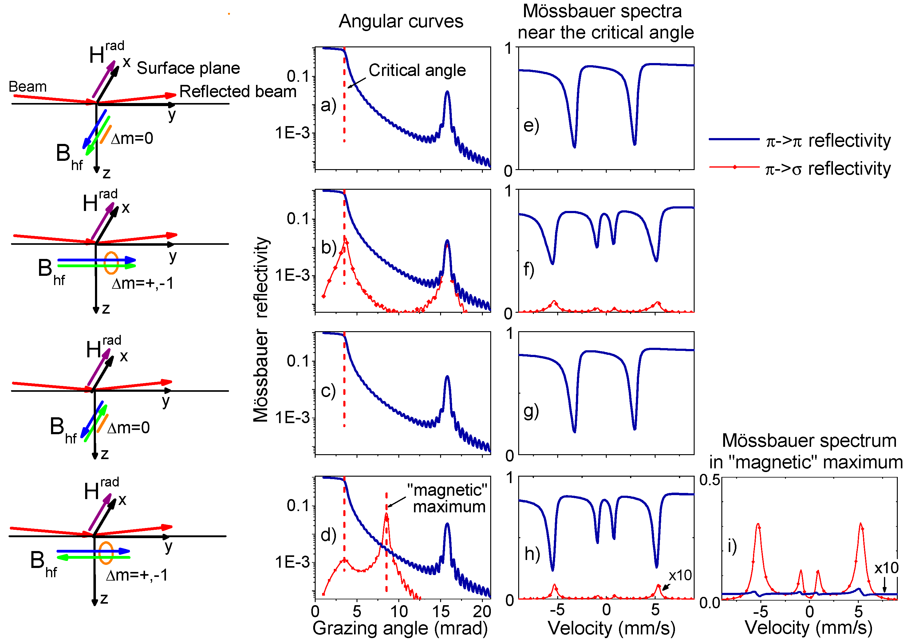
We start with the model calculations of the Mössbauer reflectivity angular curves and Mössbauer reflectivity spectra at several grazing angles using our computer code RESPC (available from the ESRF website [
46]). The essential point is that the calculations have been performed with selection of the reflected radiation by the polarization state and the result is shown in
Figure 1. The π→π reflectivity is drawn by thicker blue lines, π→σ reflectivity is drawn by thinner red lines with symbols.
In the energy-domain, the angular dependence of the Mössbauer reflectivity can be calculated either for a selected energy in the resonant spectrum range, or as the integral over the entire Mössbauer reflectivity spectra at each grazing angle θ.
Figure 1a–d show the results obtained by the integrated mode, this mode corresponds to the experimental procedure with SMS. Calculations have been done for the [
57Fe(0.8 nm)/Cr(2 nm)]
30 multilayer, in
57Fe layers we assume the presence of the hyperfine magnetic field of B
hf = 33 T with ΔB
hf = 1 T distribution. We have considered the two magnetization directions relative to the radiation beam and the two types of the interlayer coupling between adjacent
57Fe layers (ferromagnetic or antiferromagnetic), schematically shown by the blue and green arrows in the left column of
Figure 1. Note that 14.4 keV Mössbauer transition is of magnetic dipole M1 type, so the magnetic field of radiation H
rad interacts with
57Fe nuclei. In the case of the π-polarized radiation from SMS the radiation field vector H
rad lies in the sample surface. The hyperfine nuclear transitions (Δm = 0, Δm = ±1) allowed for π-polarized radiation are also indicated by orange lines in these sketches.
The results of these simple calculations show some unexpected features, not reported in previous experimental studies. The shapes of the angular curves of the Mössbauer π→π and π→σ reflectivity are found very different. For Mössbauer π→π reflectivity the angular dependences
behave as usual X-ray reflectivity (they tend to 1 when
). This behavior follows directly from usual Fresnel law, and it had been observed in the first paper devoted to Mössbauer reflectivity [
42].
On the contrary, the angular dependencies
of the Mössbauer π→σ reflectivity have a sharp peak at the critical angle of the total external reflection and approach zero when θ→0, as it seen in
Figure 1b,d.
For the antiferromagnetic interlayer coupling, the magnetic period of the structure is twice larger than the chemical period. In this case, the additional Bragg peak (“magnetic” maximum) appears in the Mössbauer reflectivity angular dependence (see
Figure 1d). Our calculations show that only the radiation with rotated π→σ polarization contributes to this peak (provided that there are no asymmetrically canted B
hf in the adjacent
57Fe layers). Accordingly, the Mössbauer spectrum at the magnetic maximum is determined practically only by π→σ scattering (see
Figure 1i). The rotated polarization component appears in the reflected signal only when the hyperfine field B
hf has a finite projection on the beam direction, i.e., when the excitation of the resonant
transitions leads to the reemission of radiation with some part of the circular polarization. Accordingly, the Mössbauer reflectivity spectra with rotated polarization show not six but only four lines corresponding to the
transitions as it takes place in
Figure 1f,h,i. In the other cases, there is no reflectivity with rotated polarization at all.
Note that the discovered behavior of the angular dependencies of the Mössbauer π→σ reflectivity resembles much the angular dependence of the delayed nuclear resonant reflectivity measured in time-domain experiments [
47]. For the delayed reflectivity, the vanishing of the delayed photons at zero grazing angle also can be explained by the Fresnel law: when θ→0 the reflectivity for all energies in Mössbauer spectrum approaches unity, entirely losing its energy dependence. Accordingly, the intensity of the delayed radiation, determined by the Fourier transform of the energy dependent reflectivity amplitude, approaches zero. The physical explanation of the peak on the delayed reflectivity curve has been suggested in [
48,
49], and it is based on the phenomena of the X-ray standing waves. It has been shown that these waves, created by the prompt SR pulse, are responsible for the excitation of resonant nuclei. The X-ray standing wave explanation works in the case of the Mössbauer π→σ reflectivity in the energy-domain as well.
The basis for such consideration is the expression, obtained in [
49], for the reflectivity from an ultrathin layer
in the case when this ultrathin layer is placed at some depth
z in a multilayer:
where
is the reflectivity from an separated ultrathin layer of thickness
d,
is the grazing angle,
is the susceptibility of this layer,
is the volume density of the scattering centers and
the amplitude of scattering in forward direction.
corresponds to the reflectivity amplitude from the part of the multilayer below the ultrathin layer, and functions
describe the transformations of the transmitted and outgoing waves during multiple reflections at all boundaries in the upper part of the multilayer:
In (8)
and
are the Fresnel and multiple reflectivity amplitudes respectively at each boundary above the ultrathin layer,
is the phase shift for the waves during their transmission through each layer
j. It is easy to see that
where
is the total amplitude of the radiation field at depth
z and
is no other than a standing wave. Assuming that
and
in (7), (6) are the matrices in the case of the anisotropic scattering like (3), (4), the following expression can be written for the off-diagonal component of the reflectivity (supposing sufficiently small) from the whole multilayer in the case of π-polarization of the incident radiation:
This component appears only due to the nuclear resonance contribution to the susceptibility and
is determined by the angular dependencies in (3), (4). The accurate derivation of (11) is presented in Ref. [
50], and its application to the X-ray resonant magnetic reflectivity has been demonstrated in Ref. [
51].
The presented expression (11) has important consequences on the features of the Mössbauer reflectivity with rotated polarization. Firstly, it explains perfectly the peak near the critical angle on the angular curve for the rotated π→σ reflectivity, because it contains the full radiation field
in the 4th power (“squared standing wave”). It is well known that the angular dependence of the secondary radiation, excited by X-ray standing waves, is characterized by the peak at the total reflection angle [
52,
53,
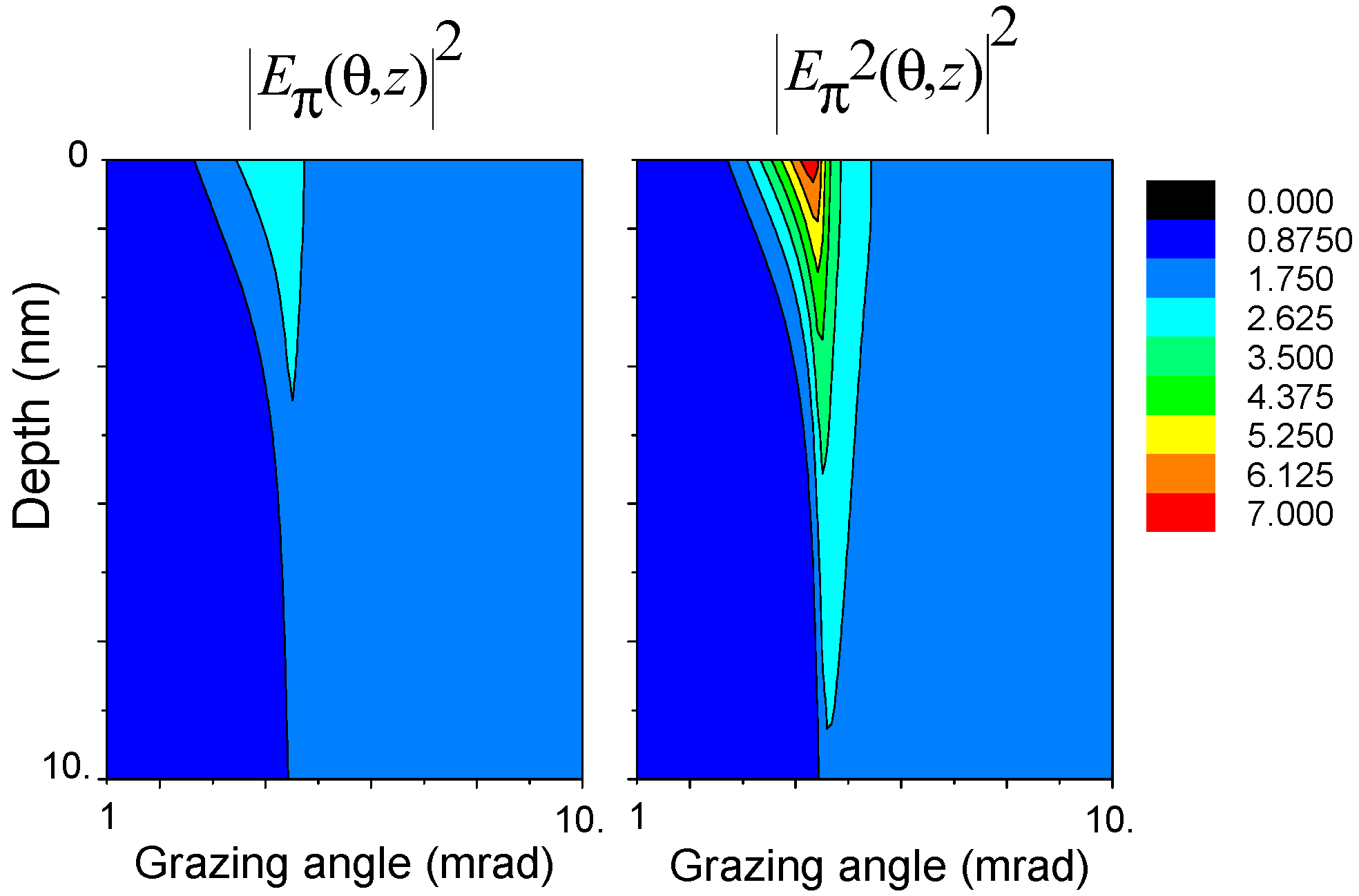
54]. Secondly, the secondary radiation emission depends on the normal standing waves
. The
factor in (11) (“squared standing wave”) supplies the enhanced depth contrast comparing with
, which is illustrated by
Figure 2. Thirdly, the expression (11) essentially simplifies and fastens the calculations of the reflectivity with rotated polarization from anisotropic multilayers. It means that if the dichroic contribution to the scattering is small, the standing waves
at depth
z of the sample can be calculated using the ordinal scalar reflectivity theory, and the “dichroic” response
is calculated by simple summation the scattering amplitudes
from different depth with proper “weights” (the generalized kinematical approximation). If the nuclear resonance scattering is strong enough, the radiation field
varies across the resonant spectrum (as seen in
Figure 3b); however, in most cases these variations of
as a function of
can be neglected especially if we measure the NRR (Nuclear Resonance Refelctivity) curves by integrating over Mössbauer reflectivity spectra. In this case the calculations become extremely fast.
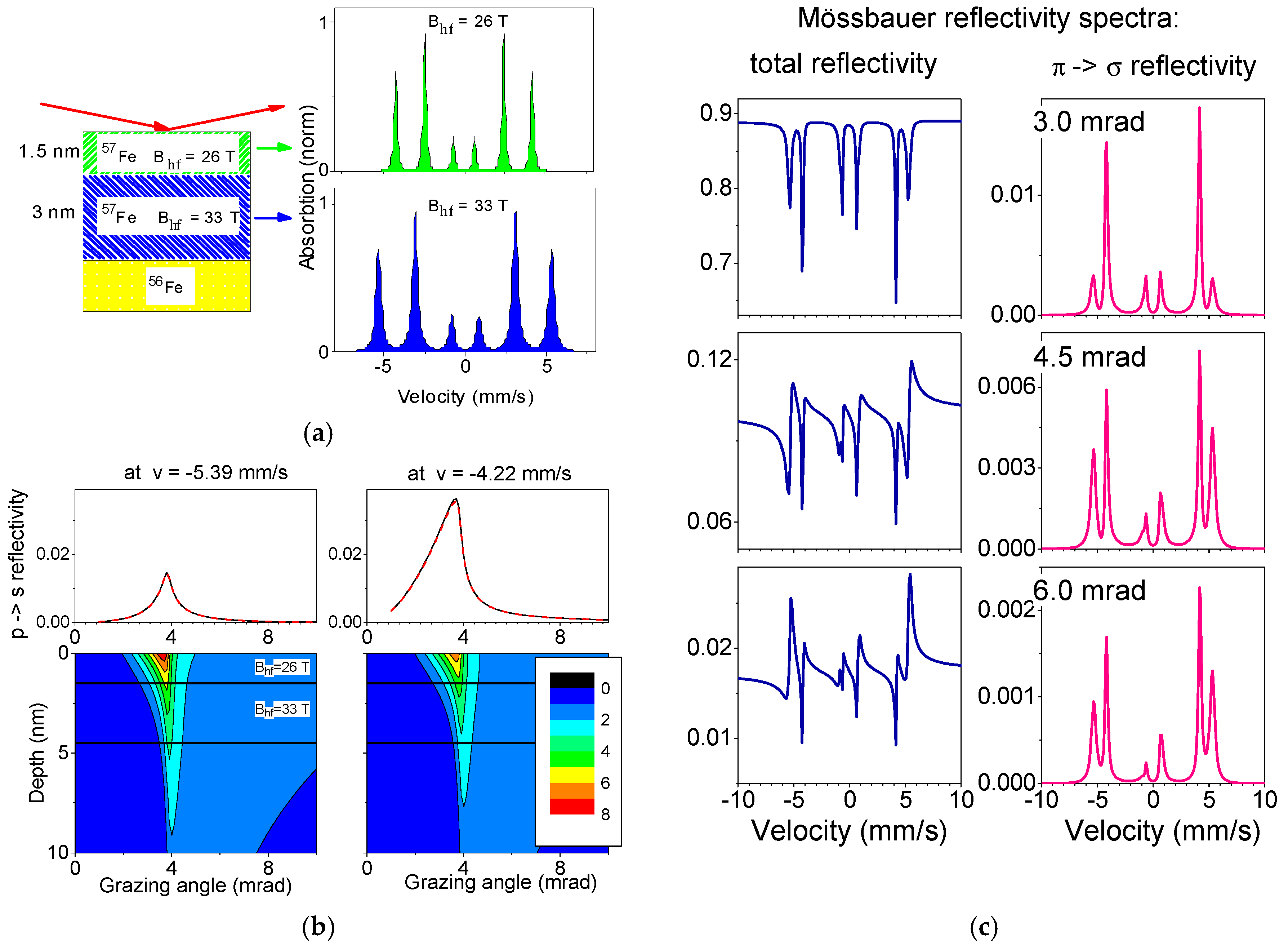
The enhanced depth selectivity of the Mössbauer π→σ reflectivity spectra compared with the ordinal Mössbauer reflectivity spectra is illustrated by
Figure 3. In order to distinguish the thin top layer (1.5 nm
57Fe) from the bottom one, we assumed for the top layer the hyperfine magnetic field B
hf = 28 T, and for the deeper
57Fe layer (3 nm thickness) B
hf = 30 T. The calculated Mössbauer reflectivity spectra at several grazing angles near the critical one without and with π→σ polarization selection clearly show that the π→σ reflectivity spectra contain more intense contribution from the 1.5 nm top layer than the Mössbauer reflectivity spectra without polarization selection.
The validity of the generalized kinematical approximation (11) is also checked by calculations presented in
Figure 3b. The angular curves in
Figure 3b are calculated in two ways: by the formula (11) and by the exact calculations performed with the program pack REFSPC [
46] (solid and dashed lines respectively). Both results coincide. However, in order to achieve this practically full coincidence, the nuclear resonant susceptibility was decreased by a factor of 5 relative to the value for the α-iron films fully enriched by
57Fe isotope. Such decreased nuclear resonance susceptibility is typical for real thin films with lower enrichment and broad distribution of the hyperfine magnetic fields. Thereby, the direct comparison between the kinematical approximation (11) and the exact calculations shows the excellent agreement, provided that the resonant contribution to the susceptibility is not too large.
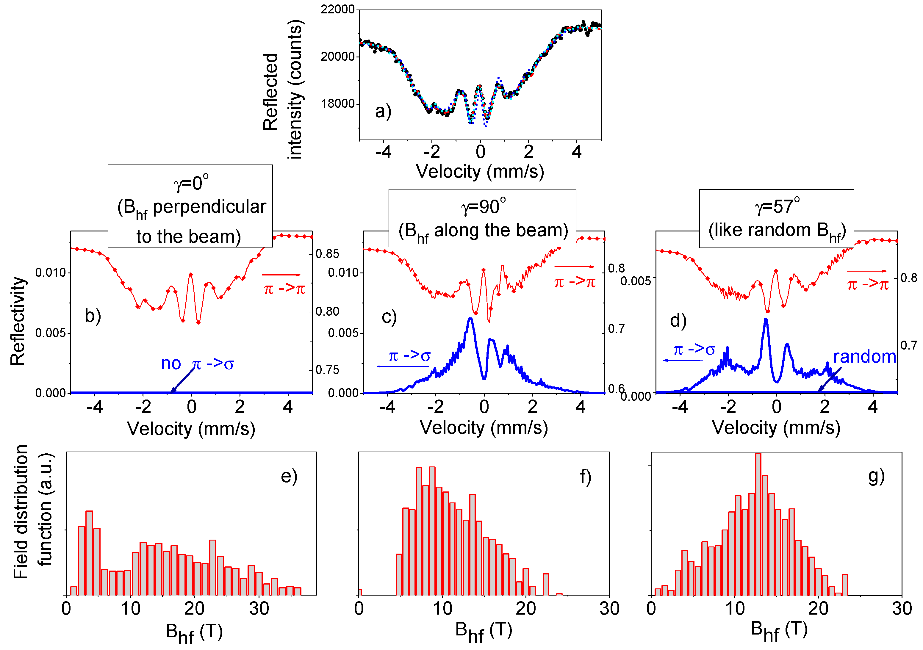
The next advantage of the measurements with the selection of polarization is illustrated by
Figure 4. It shows that the selection of polarization leads to the decreasing number of lines in the Mössbaur reflectivity spectra. This can be very useful for the interpretation of the poorly resolved complicated spectra. The experimental Mössbaur reflectivity spectrum from Ref. [
55], presented on the top of
Figure 4, can be fitted by at least three different models with completely different field orientation and distribution of the hyperfine magnetic field. The calculated π→σ reflectivity spectra are quite different for these three cases. Therefore, the true picture of the hyperfine field distribution and orientation can be recovered if one performs the polarization analysis of the reflected radiation.
3. Experimental Results and Discussion
The experiment has been performed at the Nuclear Resonance beamline [
56] ID18 of the ESRF.
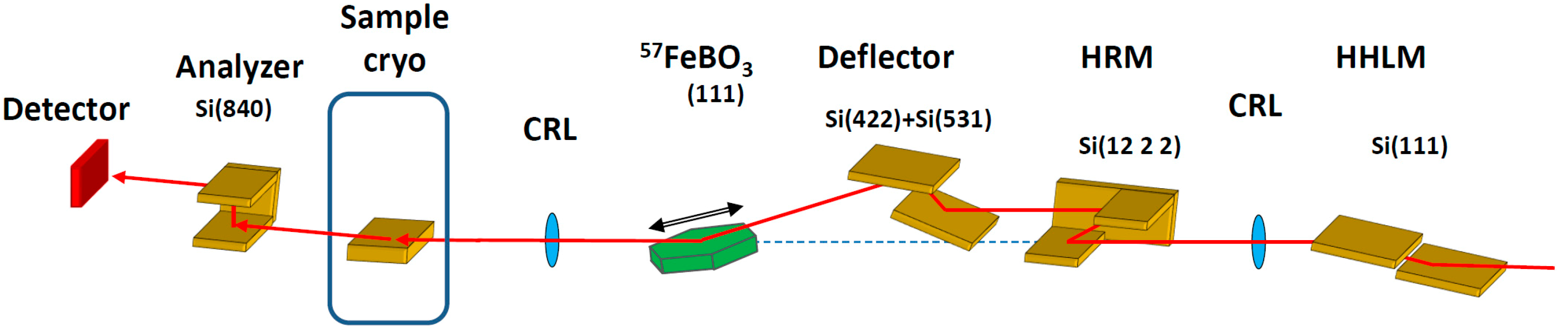
Figure 5 shows the experimental setup. The storage ring was operated in multi-bunch mode with a nominal current of 200 mA. The energy bandwidth of radiation was first reduced down to 2.1 eV by the high-heat-load monochromator [
57] adjusted to the 14.4125 keV energy of the nuclear resonant transition of the
57Fe isotope. Then X-rays were collimated by the compound refractive lenses down to the angular divergence of a few μrad. The high-resolution monochromator decreases the energy bandwidth of the beam further to ~15 meV. Final monochromatization down to the energy bandwidth of ~8 neV was achieved with the pure nuclear (111) reflection of the
57FeBO
3 crystal, and the sweep through the energy range of a Mössbauer resonant spectrum (about ±0.5 μeV) was achieved using the Doppler velocity scan. Radiation from the SMS was focused vertically using the compound refractive lenses down to the beam spot of 50 μm. The intensity of the X-ray beam incident on the sample was about 10
4 photons/s. More details on the design of the SMS can be found in Ref [
37].
The selection of the radiation with the rotated (π→σ) polarization was performed by silicon channel-cut crystal with two asymmetric Si(840) reflections with the Bragg angle θB = 45.1°. According to theoretical calculations, the channel-cut should suppress the π-polarized radiation by about five orders of magnitude, while transmitting about 70% of the ⌠-polarized radiation with the angular acceptance of about 2.6 arc sec (FWHM).
We studied several [
57Fe/Cr]
30 samples. The samples were grown with the Katun-C molecular beam epitaxy facility, equipped by 5 thermal evaporators at the Institute of Metal Physics (Ekaterinburg, Russia). The growth was performed under the UHV (Ultra-high vacuum) regime (5 × 10
−10 mbar). During the buffer layer deposition, the Al
2O
3 substrate temperature was gradually decreased from 300 °C down to 180 °C. The typical deposition rate of Cr and
57Fe layers was about of 0.15 nm/min. The details on the preparations and characterization of the samples can be found elsewhere [
38]. The samples were mounted in the cassette holder of the He-exchange gas superconducting cryo-magnetic system. The studies were performed at helium temperature (4.0 K).
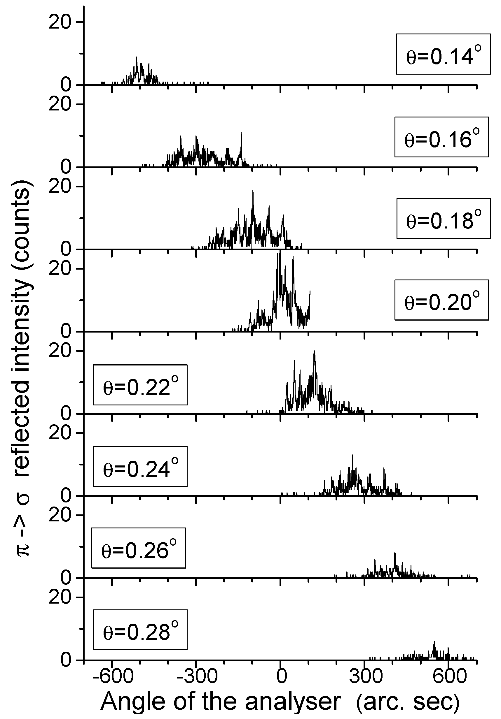
The angular scan with the polarization analyzer, performed for all used samples in order to catch the π→σ reflected radiation, demonstrated the extremely broadened divergence of the reflected signal as it is shown in
Figure 6 for one of the sample. In essence, the samples were composed of many nano-crystallites, essentially misoriented relative to each other. Consequently, the radiation reflected by the sample consisted of many spikes, spreading over the angular range of about 200 arc sec as seen in
Figure 6. For such a divergent reflected beam, the throughput of the Si(840) channel-cut analyzer for the σ-polarized radiation was only about 4%. Therefore, the measurements of the reflectivity with the rotated π→σ polarization were essentially complicated by the nano-islands structure of the studied samples. Later we get the GISAXS (Grazing-incidence small-angle X-ray scattering) pattern from this sample which shows the cluster-layered structure of the whole film [
58].
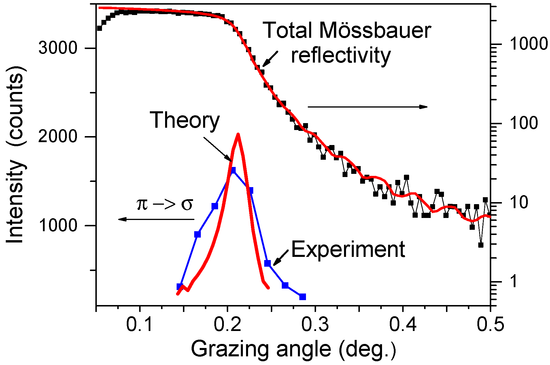
With the resulting very small count rate, the measurements at the weak “magnetic” maxima for the samples with antiferromagnetic interlayer coupling were not feasible, and we decided to concentrate on measurements near the critical angle. In order to ensure the ferromagnetic alignment of the magnetization in the 57Fe layers and increase the Mössbauer dichroic reflectivity, the external magnetic field of 5 T was applied along the beam direction.
In order to increase the count rate, the temperature of the
57FeBO
3 crystal for this particular measurement was lowered by few degrees. This sacrifices the energy resolution of the SMS to ~230 neV (~5 mm/s), which is not important for the angular dependency measurements, but increases the intensity of the SMS by an order of magnitude [
37]. The nuclear resonance reflectivity with the rotated polarization shown in
Figure 7 was obtained for each grazing angle θ by integrating over the angular distributions measured with the Si(840) analyzer and drawn in
Figure 6.
The predicted peak near the critical angle for the Mössbauer
reflectivity is clearly seen in
Figure 7. The origin of this peak is already explained in the previous section. The angular dependence of the Mössbauer reflectivity measured without the polarization selection shows the plateau below the critical angle. Note that the signal values for two curves in
Figure 7 are not possible to compare because they are measured with different incident intensities from
57FeBO
3 nuclear monochromator.
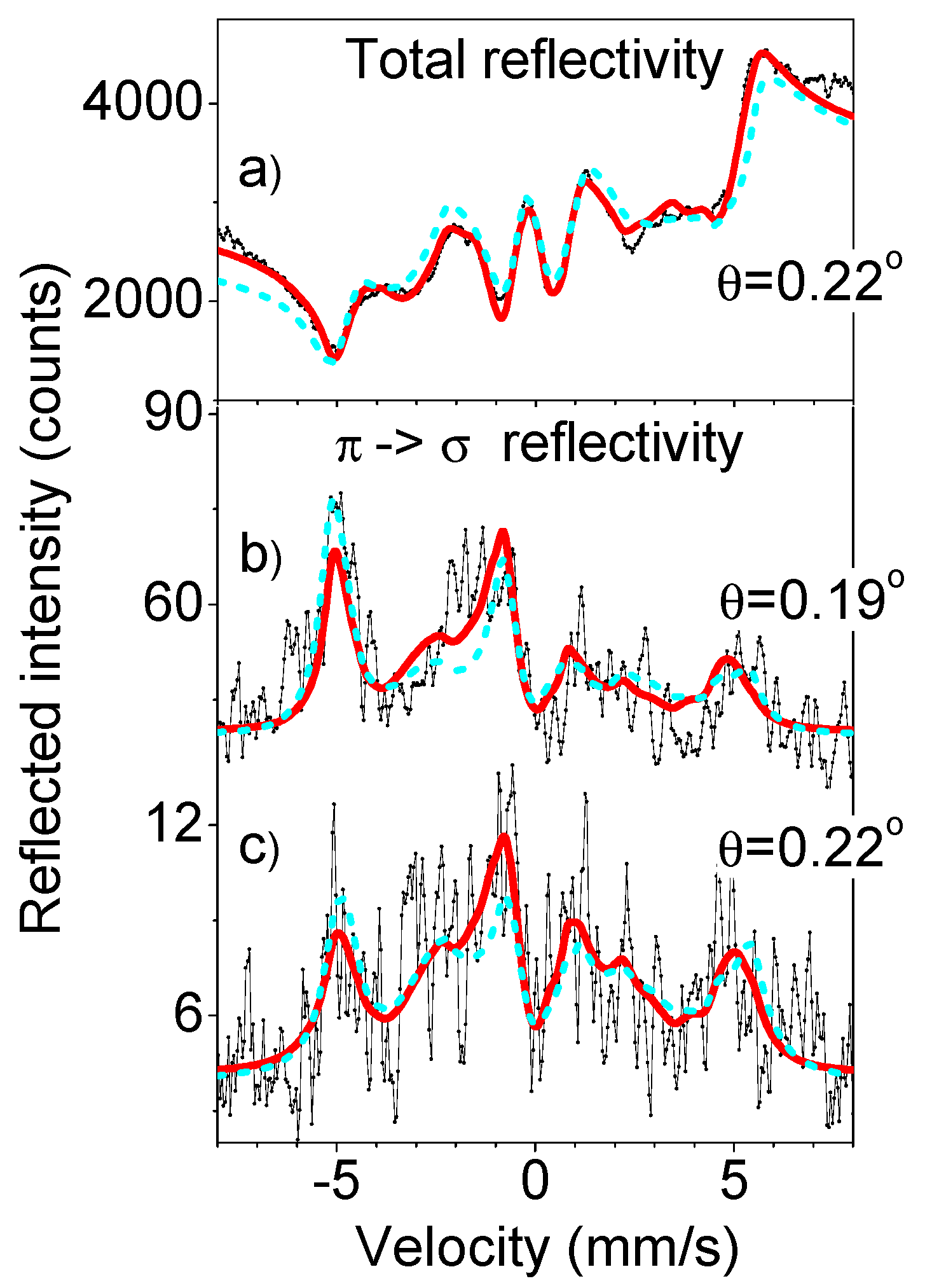
Mössbauer
reflectivity spectra were measured at the two grazing angels, θ = 0.19° and θ = 0.22°, in vicinity of the critical angle. They are shown in
Figure 8. In spite of the limited statistics, caused by the essential loss of the intensity due to the nano-islands structure of the samples and narrow angular reception by ideal Si crystal-analyzer, we can recognize in these data some important features. The resonant lines are presented in these spectra as peaks, as predicted by the theory (see
Figure 1f,h,g). The spectrum measured without polarization analysis is also presented in
Figure 8 for comparison. The lines in this spectrum have a dispersive-like shape and they are essentially broadened, as it should be at the angles near the critical angle [
46]. Note, that in spite of the higher statistical accuracy of the spectrum measured without the polarization analysis, its smeared shape makes the correct interpretation more difficult. Thus, the spectra of reflectivity with rotated polarization should be more suited for the right data analysis, provided that better statistics will be reached by optimization of the experiment.
The fit of the
reflectivity spectra is not really reliable due to insufficient statistics, we merely wanted to show what treatment should be performed with better experimental data and demonstrate the surface sensitivity of the method. So, the shapes of the spectra in
Figure 8 can be more or less reproduced by the fit performed with the REFSPC program package [
46]. All three spectra are treated within the same model. We have used seven hyperfine fields B
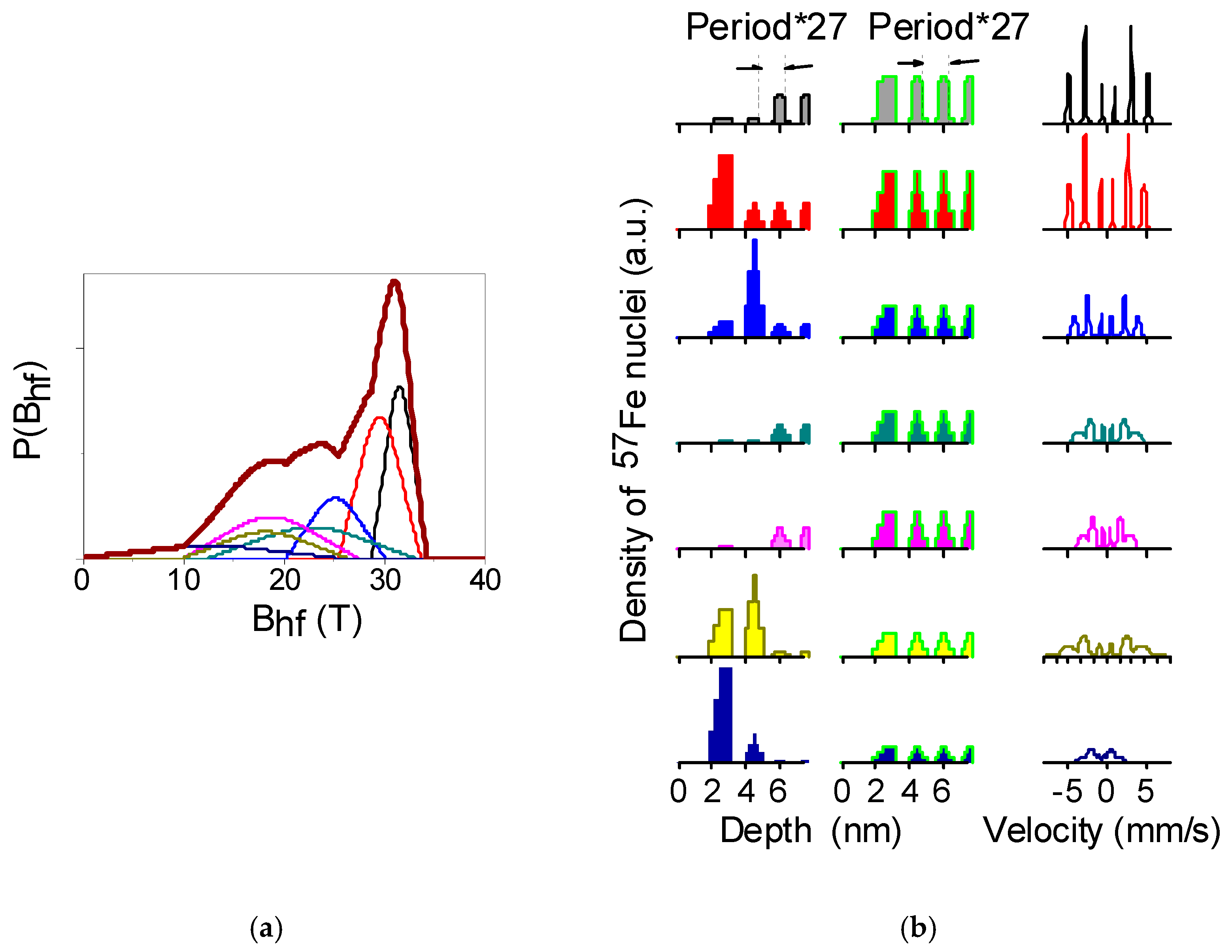
hf(i), i = 1, 2, …, 7, and the fitted parameters and distribution probabilities of the fields
P(B
hf) are shown in
Figure 9a.
The depth profiles obtained for each field B
hf(i) are presented in the left column of
Figure 9b. We can see that the hyperfine fields in the top two
57Fe layers are significantly different from the fields in the deeper layers: on average, in the top layers the hyperfine splitting is smaller, and the fraction of the low field contributions is larger. Assuming the same field distribution in the top layers as in the whole periodic part (shown in
Figure 9b, middle column), we obtain the theoretical spectra, presented by dashed green lines in
Figure 8. They reveal worse correspondence with the experimental spectra. These calculations confirm the enhanced depth selectivity of the spectra of reflectivity with rotated π→σ polarization.
Other unexpected features of the measured spectra were noticed. We were surprised by the asymmetry and by the difference in shapes of the
reflectivity spectra measured at the two close angels: θ = 0.19° and θ = 0.22° (compare the spectra in
Figure 8b,c). At the beginning we supposed that these effects are caused by a small contribution of the reflectivity with the non-rotated polarization. But the model calculations did not confirm such assumption. Finally, the effect was explained by the refraction effect.
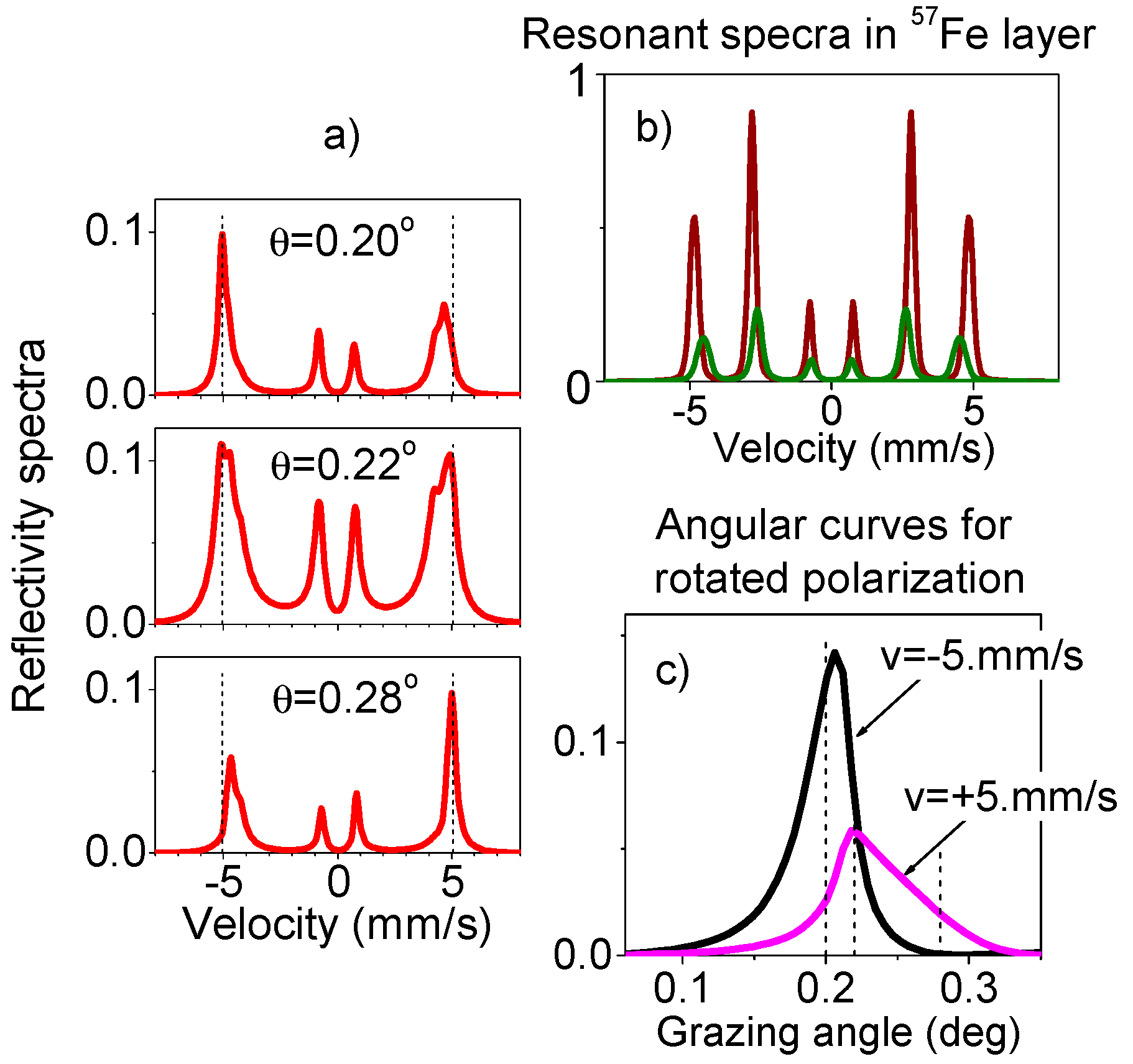
For illustration of this effect we use a simple model. Calculations have been performed for the 10 nm
57Fe layer where two hyperfine fields B
hf = 28 T and 30 T take place, the resonant spectra for these two fields are drown in
Figure 10b. The angular dependencies of the Mössbauer
reflectivity, calculated for the photon energies corresponding to two outer lines in these spectra reveal the different angular positions of the critical angle peaks which is clearly seen in
Figure 10c. This shift of the peak positions explains the asymmetry of the rotated π→σ polarization component in Mössbauer reflectivity spectra.
The position of the critical angle is determined by the real part of the susceptibility
of the layer (or the refraction index
). For nuclear resonance scattering, this includes the electronic scattering part and the nuclear resonant contribution. The real part of the nuclear resonant contribution has the opposite signs at two sides of the exact resonance. Therefore, the resonant lines of the narrower sextet with B
hf = 28 T have opposite influences on the refraction index and, accordingly, on the critical angle position for the radiation wavelengths corresponding to the 1st and 6th lines of the broader sextet. Because the maximum of reflectivity for these two lines occurs at slightly different angles, the relative intensities of these two lines are not the same (as they are supposed to be for the absorption case), and they are changed with a small variation of the grazing angle. This provides the observed asymmetry of the spectra depending on the small variation of the grazing angle observed in
Figure 8. Note that the studied sample shows even more low-field B
hf(i) contributions. However, the effect of all smaller fields is, in principle, the same as revealed by the simplest model calculations.
Note that the same changes of the asymmetry of the Mössbauer reflectivity spectra were observed with this particular sample in measurements at the “magnetic” maximum [
59]. Although those measurements were performed without the polarization analysis, the “magnetic” maximum is formed basically by the scattering with the rotated π→σ polarization (as shown by the model calculations in
Figure 1d,i).
4. Summary
We have performed the first experiment on the nuclear resonant reflectivity in the energy domain with the polarization selection, with the two asymmetric Si(840) reflections from a silicon channel-cut crystal. The experiment has been performed using the synchrotron Mössbauer source, benefiting from the purely linear π-polarized radiation of this instrument. We have measured the angular dependence of the π→σ reflectivity as well as the Mössbauer π→σ reflectivity spectra at two angles in vicinity of the total external reflection.
We have observed a new effect not reported before. Namely, the nuclear resonance (Mössbauer) π→σ reflectivity in the energy domain is characterized by a peak near critical angle of the total external reflection (instead of the Fresnel plateau) similar to that observed for the nuclear resonant reflectivity in the time domain. The effect is explained by the influence of the X-ray standing waves on the nuclear resonant scattering.
Our first experimental realization of the new method shows that, for the polarization analysis in reflectivity experiments, a thorough choice of the right way of polarization selection is needed. The reason is that the reflectivity from cluster-layered films has essentially broadened angular divergence due to a surface roughness and other imperfections. The channel-cut Si (840) reflection, effectively used in previous polarization experiments in forward scattering or for crystal diffraction [
32,
33] has angular acceptance that is too small and we lost most of the reflected radiation. For this reason, the quality of the measured Mössbauer π→σ reflectivity spectra was not good enough for quantitative interpretation and our fit just demonstrates the future possibilities. It is clear that other polarization analyzers should be tested (e.g., Be (006) reflection, LiF (622) reflection, Ge (664) reflection, a pyrolytic graphite (222) reflection or some others for 14.4 kev radiation etc.) in order to enlarge the registered signal. Note that in the soft X-ray region a rather unusual way of polarization selection is used (an electron time-of-flight polarization analyzer) [
60]. In [
61] an annealed silicon crystal was used in order to enlarge the angular acceptance of this monochromator/analyzer. We believe that the right choice of the polarization analyzer allows one to measure Mössbauer π→σ reflectivity with essentially better statistics and to use and demonstrate all theoretically described advantages of the new method of registration.
We have shown (at least by model calculations) that the polarization analysis in Mossbauer spectroscopy simplifies the Mössbauer spectra, restricting the number of lines. It should be helpful for their interpretation in cases of complicated hyperfine interactions (typical for Mössbauer nuclei at a surface, in nano-objects and in thin layers). Moreover, in the reflectivity geometry the spectra lost the dispersive-like features caused by the interference of nuclear and electronic scattering. The enhanced surface sensitivity of the reflectivity signal with rotated π→σ polarization is also predicted, which follows from the “squared-standing-wave” depth dependence of the scattered radiation.
Concluding, we believe that the described advantages of Mössbauer spectroscopy with polarization selection will help to resolve most important scientific cases in surface science, with new physics and high data quality, and will provide us with a more reliable interpretation of the magnetic ordering in multilayer films.

 ,
, 


