Article

Sea Bass (Dicentrarchus labrax) Tail-Beat Frequency Measurement Using Implanted Bioimpedance Sensing

1
LIRMM, Univ. Montpellier, CNRS, Montpellier, France
2
IFREMER, DOI, France
3
MARBEC, Univ. Montpellier, CNRS, IFREMER, IRD, Montpellier, France
*
Author to whom correspondence should be addressed.
Fishes 2024, 9(10), 399; https://doi.org/10.3390/fishes9100399
Submission received: 24 July 2024 / Revised: 27 September 2024 / Accepted: 30 September 2024 / Published: 1 October 2024
(This article belongs to the Special Issue Technology for Fish and Fishery Monitoring)

Abstract

:
Estimating tailbeat frequency (TBF) is a crucial component of fish swimming kinematics and performance, particularly because it provides information about energetics and behavioral responses to environmental cues. The most commonly used technique for TBF estimation is based on accelerometers. This paper proposes a novel approach using bioimpedance technology. This is the first time bioimpedance has been measured in a freely moving animal. This was made possible by implanting a flexible electrode in the back muscle of seabasses and having them in a swimming tunnel. The experiment first demonstrates that it is possible to measure bioimpedance in an immersed fish despite the high conductivity of seawater. An agreement analysis was then performed to compare a video-based reference measurement of TBF with the newly proposed approach. Several bioimpedance settings, such as the configuration and the extracted electrical parameters, were considered. Data analysis highlights that a 4-point setup for modulus impedance measurement at frequencies over 10 k Hz provides the best agreement (r > 0.98 and CCC > 0.97) with the video-based approach. These results attest to the significant benefits of integrating bioimpedance sensors in biologgers, especially considering the complementary parameters that can be extracted from bioimpedance measurements, such as length, weight, condition index, and fat content.
Key Contribution: The first key contribution is the first experiment consisting of measuring bioimpedance in a moving animal. The second contribution is the tail-beat frequency estimation of seabass using bioimpedance, and the agreement analysis using video-based technique is the golden one.

1. Introduction

Tailbeat frequency (TBF) is a key component of fish swimming kinematics and performance. It is well established that swimming speed increases linearly with TBF in fish that use body-caudal locomotion [1,2,3], and TBF can provide information about fish swimming energetics through the relationship between swimming speed and oxygen uptake and can also reveal behavioral responses to environmental cues. For example, estimating the swimming speeds and spontaneous behaviors of large pelagic fishes has been a primary objective of TBF studies (e.g., [4]).
Generally, however, monitoring TBF is performed under experimental conditions. The initial scientific approach to estimating maximum TBF involved measuring minimum muscle contraction times [5,6]. Current monitoring techniques include video analysis, underwater echosounders [7], and biologgers equipped with accelerometers [8,9,10]. Accelerometers are now the most widely used technique for the measurement of TBF in freely swimming fish. Ref. [11], with various applications such as the following:
  • Remotely describing and identifying in situ behaviors like spawning [12], feeding [13], escaping [13], and fast-start events [14].
  • Predicting oxygen consumption [15,16] and metabolic rate [17].
Accelerometers are commonly embedded in consumer electronics like cellphones and tablets, so they have benefited from significant industrial development, reducing their size so that they can be integrated. Consequently, accelerometers are now included in most commercial biologgers. However, there are some drawbacks. For instance, the sensor often requires calibration through controlled experiments. Additionally, for speed estimation using TBF, the fish size must be known, which limits sensor deployment in natural conditions to short periods, assuming limited growth.
The main objective of the experimentation described in this publication is to explore the feasability and benefits of using a new sensing technique called bioimpedance to measure the TBF of the seabass (Dicentrarchus labrax) and to realize an agreement analysis between this new sensing technique and a golden one based on video. The primary purpose of this study, therefore, was to perform the first bioimpedance measurement on a moving fish in an aggressive chemical environment for electronics, seawater. The second objective was to assess the impact of fish activity on bioimpedance signals, in particular to investigate the relationship between dynamic bioimpedance variations and fish TBF.

2. Bioimpedance Measurement Principle and Applications

This paper introduces a novel sensing technique for fish TBF estimation based on bioimpedance. Bioimpedance combines the concepts of biology and electrical impedance, referring to the measurement of electrical impedance in biological tissues. Electrical impedance is a parameter that provides information about how a conductive element impedes the flow of electric current [18]. The basic principle of bioimpedance measurement [19] involves either applying an electric current (I) and measuring the resulting electrical potential difference (V), or applying an electrical potential difference and measuring the resulting current flow. Impedance is defined as the ratio between the electrical potential difference and the electric current flow, as provided by Equation (1).
z = U I
Bioimpedance can be measured using two different measurement setups, namely 2-point or 4-point measurement techniques (Figure 1). In the 2-point, both the electrical signal generation and measurement are performed using the same contacts. In contrast, the 4-point technique uses two pairs of contacts, one for signal generation and one for measurement. The advantage of the 4-point over the 2-point technique is the reduced amount of disturbance due to the limited impedance interface on the measuring contacts.
Electrical impedance extends Ohm’s law to alternating signals, meaning that both the generated and measured signals are sine waves. One of the main characteristics of a sine wave is its frequency. Bioimpedance spectroscopy, as the name suggests, measures over a range of signal frequencies [19]. Bioimpedance spectroscopy is significant because the response of biological tissues to the electrical current flow depends on the frequency. Additionally, as shown in Equation (2), impedance z is a complex number that can be expressed in an algebraic form with a real component ( R e ( z ) ) and an imaginary component ( I m ( z ) ). It can also be expressed in a polar form with the modulus ( r = | z | ) and the argument ( θ = a r g ( z ) ).
z = R e ( z ) + i · I m ( z ) = r e i θ
Since bioimpedance signatures can integrate all the biological processes that influence tissue composition, the method has numerous and varied applications. Bioimpedance was originally developed for medical applications but, over the past 20 years, its use has expanded to veterinary applications, especially body composition analysis [18,19,20,21,22,23,24,25]. This relies on a specific measurement setup [19], involving either an inert patient in medical applications or an anesthetized subject in veterinary applications, with two electrodes and two contacts at the extremities of the body. Bioimpedance data are then combined with additional data, such as morphometric parameters, in predictive models.
There are very few applications focused on dynamic processes. In the medical domain, impedance is used for cardiography [18] and can also be used for estimating chest movement and respiratory volume [26]. To our knowledge, however, there are no examples of dynamic bioimpedance measurement on animals.

3. Materials and Methods

3.1. Ethical Approval

Experimental procedures were approved by the ethics committee for animal experimentation n° 036 of the French Ministère de l’Enseignement Superieur, de la Recherche et de l’Innovation, with reference number APAFIS 10130-201704071516253 v3.

3.2. Materials

3.2.1. Animals

Experiments were performed on n = 8 seabass (Dicentrarchus labrax) with a mass of approximately 600 g that were bred and reared at the Ifremer Marine Research Platform in Palavas-les-Flots (Hérault Department, France), in indoor cylindrical tanks (vol 5 m 3 ) under seasonal photoperiods, provided with a flow of biofiltered and UV-treated seawater at 21 °C. Fish were fed daily with commercial pellets (B-Grower Marin, Le Gouessant, Lamballe-Armor, France www.legouessant.com) but fasted for 24 h prior to surgery.

3.2.2. Bioimpedance Measurement

Prototypes of implantable 4-contact electrodes, usable for both 2-contact and 4-contact bioimpedance measurements, with platinum contacts on a flat leaf of semi-rigid Kapton [27] have been used for bioimpedance measurement. The electrodes were connected to a MFIA Zurich Instruments impedance analyzer, connected to a computer, and controlled using Matlab 2020 software.

3.2.3. Respirometer

In order to be able to make measurements using laboratory instruments while the seabasses were moving, we used a respirometer. The respirometer is designed to provide a non-turbulent water flow with a uniform velocity profile in which to exercise fish at controlled current speeds. The anterior portion of the swim section was shielded with black plastic sheeting to avoid visual disturbance of fish, which spontaneously occupied this area.

3.2.4. Video

Fish were filmed at each speed for subsequent calculation of their TBF using a GoPro 7 (1080 p, 30 fps).

3.3. Methods

3.3.1. Surgery

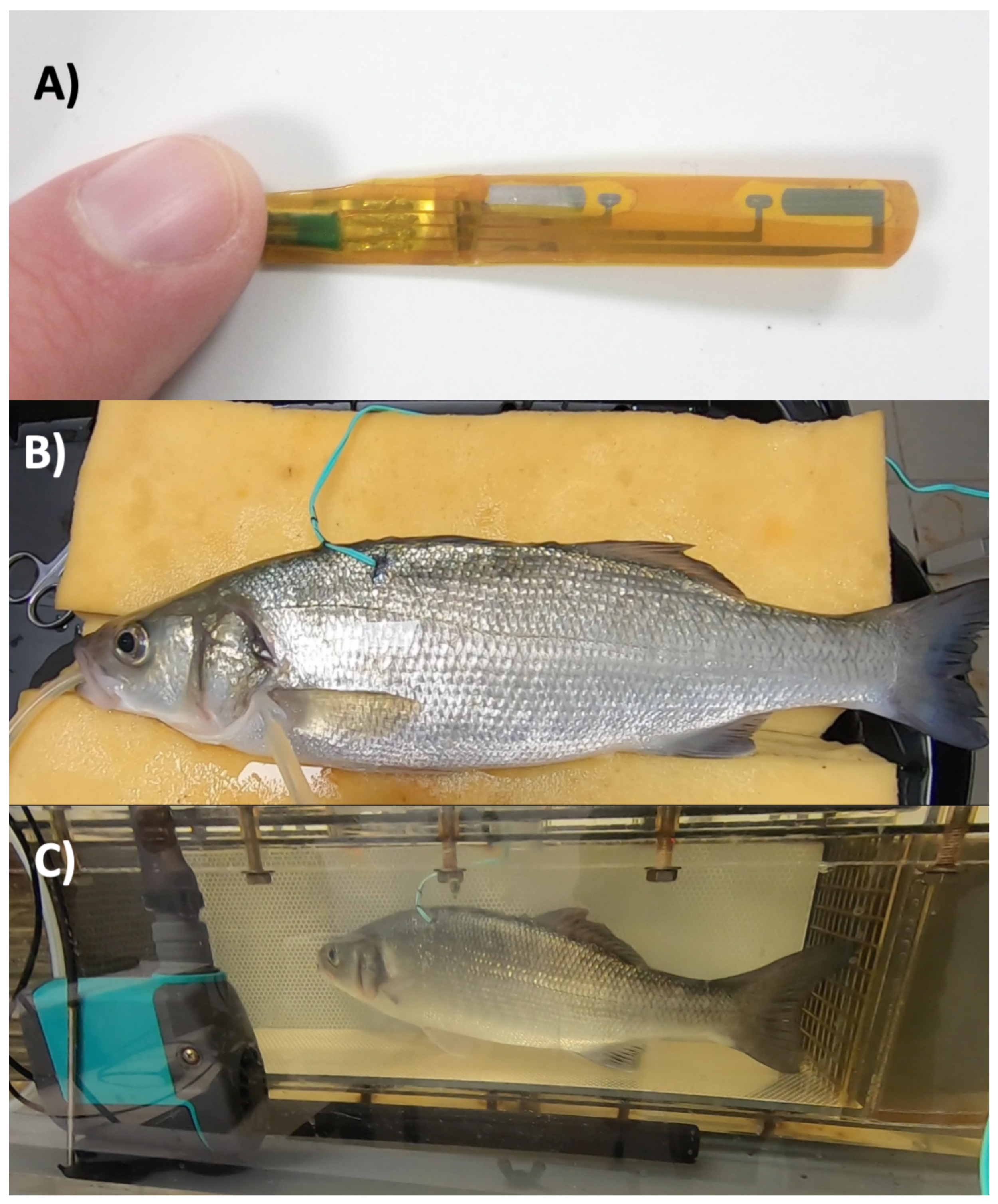
Fish were anesthetized by immersion in 0.1   g   L −1 benzocaine (Benzocaine ethyl 4-Aminobenzoate, VWR, Rosny-sous-Bois, France, www.vwr.com) in aerated seawater until active ventilation ceased, then weighed and placed on their side on an operating table with their gills irrigated with aerated seawater containing 0.05   g   L −1 benzocaine. A one cm long vertical incision was made in the skin, halfway between the dorsal fin and the lateral line and at the level of the fourth dorsal fin ray, to reveal the underlying axial musculature. A blunt dissector was gently advanced under the skin to free it from the musculature and create a space into which the impedance electrode could be advanced. The electrode (cf. Figure 2A) was slid under the skin through the incision, which was closed with sutures to hold the electrode in place. The wires were then sutured firmly to the skin at the point of electrode insertion and again on the back of the fish, just anterior to the dorsal fin (cf. Figure 2B). After surgery, fish were left to recover for 24 h in a Steffensen-type swim tunnel respirometer (vol. 30 L ) provided with a flow of aerated, biofiltered, and UV-treated seawater at 21 °C, swimming in a current equivalent to 0.5 body lengths per second ( bl / s ) (cf. Figure 2C).

3.3.2. Respirometer

Each seabass was exposed to progressive increments of swimming speed of 0.5   bl / s each 30 min until fatigue. Fish were considered fatigued when they rested their caudal fins on the downstream grid for at least 10 s .

3.3.3. Bioimpedance Measurement

For each seabass and at each speed, bioimpedance was measured several times, for 16 s each, considering two varying parameters:
  • Measurement setup: 4-point (4 pts) or 2-point (2 pts).
  • Bioimpedance frequencies for each measurement: 100 Hz , 1 k Hz , 10 k Hz , 100 k Hz , 1 M Hz , and 5 M Hz .
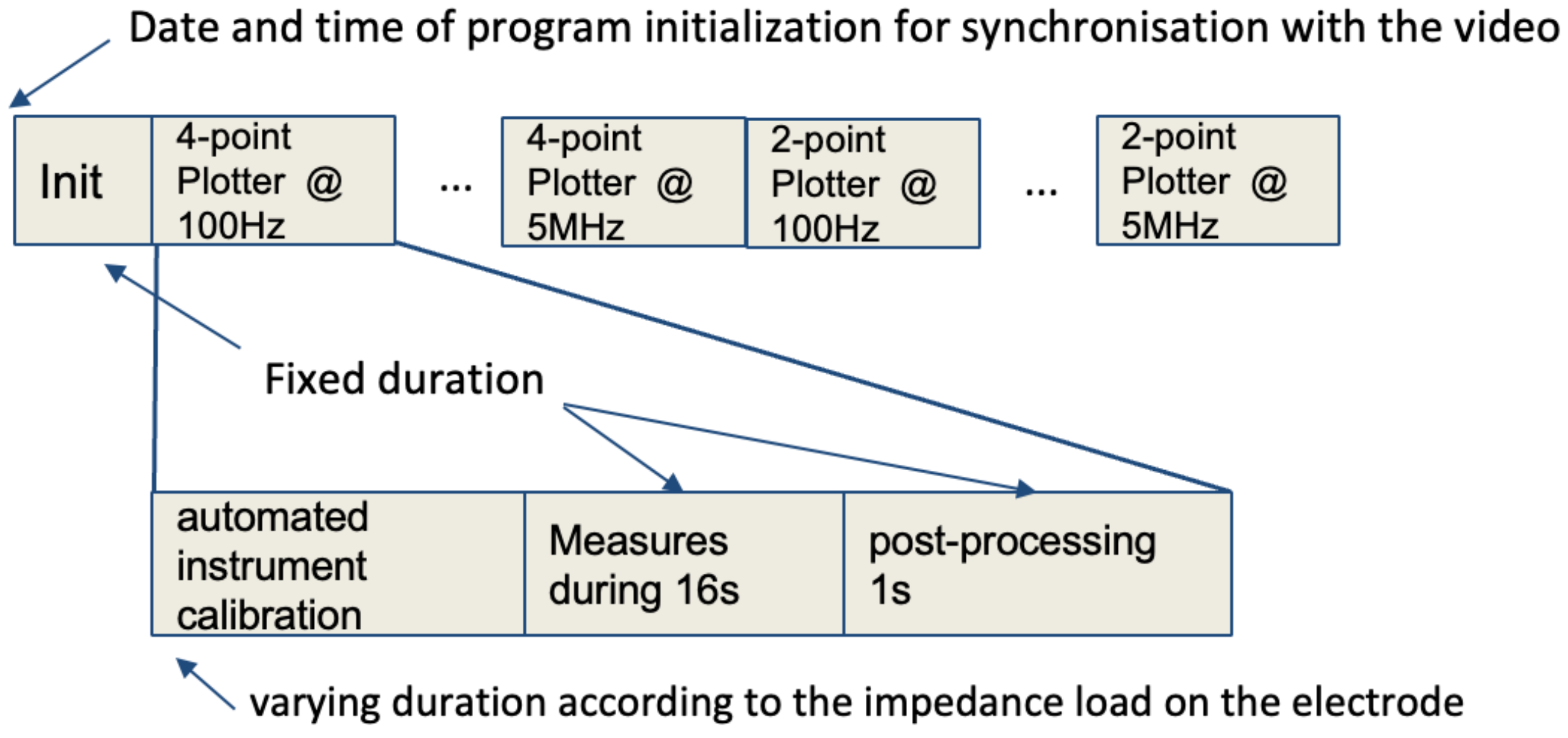
This provided 12 bioimpedance plotter measurements. The sequential timing of the measurement series at a given speed is shown in Figure 3. The upper sequence describes the sequential progress of measurements on a fish at one speed. It comprised an initialization phase and 12 16-s plotter measurements (6 signal frequencies from 100 Hz to 5 M Hz and 2 measurement setups: 2 and 4 pts). The lower sequence presents the three steps performed in each of the 12 16-s plotter measurements. Each plotter measurement includes an automated calibration of the impedance analyzer, then a 16 s measurement, then data post-processing. Amongst the four different functions (Init, automated calibration, measurement, post-processing), three of them had a fixed duration (Init, measurement, post-processing). On the contrary, the automated calibration duration varied with the impedance load variation due to fish movement and measurement frequency variation, which resulted in approximate synchronization between video and bioimpedance measurement.
As previously mentioned, bioimpedance is a complex parameter that can be expressed in an algebraic or polar form, resulting in four electrical parameters extracted from each bioimpedance measurement (modulus, angle, real part, imaginary part). As a consequence, for each fish at each speed, this resulted in 48 time series measurements.

3.4. Data Analysis

3.4.1. Video

In order to synchronize video and bioimpedance measurements, the date and time on the computer were filmed at the start of each bioimpedance measurement series. The date and time of the computer were also stored by the Matlab 2020 program at the beginning of each bioimpedance series. As presented in Figure 3, at each swimming speed, the plotter measurements were performed sequentially with some known timings except the automated instrument calibration that was done before each plotter with a timing varying from 8 s to 9 s . Considering this unknown timing, we extracted 16 s videos for each plotter that were approximately synchronized with it. Then, we counted the time, in milliseconds, for the fish to perform 10 tailbeats and then resolved this into TBF in Hz . Two fish had intermittent movements, with some time resting in the corner or at the back of the swimming tunnel, which caused some erroneous TBF estimations. Data from those two fish were, therefore, removed from the dataset for further analysis. Using the video-based TBF estimation, the stride length at each water speed was computed as presented by Equation (3).
stridelength ( bl ) = water   speed   ( bl / s ) / TBF ( Hz )
For analysis, stride length and TBF versus water speed were plotted. Fish activity data were exhibited as a plot of the average (± standard error) of measures done over the 12 videos for each water speed. Stride length is a commonly estimated parameter in fish activity studies. We aim to measure it to validate the correct operation of the experimentation.

3.4.2. Bioimpedance

As previously mentioned, for each fish and at each speed, 48 time series were extracted from bioimpedance measurements, for a Fast Fourier Transformation (FFT) on each time series. FFT was used to observe frequency patterns in the bioimpedance variation over time. Then, considering the range from 1 Hz to 5 Hz band, the frequency bin with the maximum amplitude was measured and considered to be TBF. For graphical analyses, bioimpedance-based TBF estimations were plotted at each speed, considering a reduced number of bioimpedance parameters (one setup, one electrical parameter, for instance).

3.4.3. Statistical Analysis

The first analysis focused on the relationship between bioimpedance-based and video-based fish TBF measurements, considering the two bioimpedance measurement setups and the four electrical parameters for each of these without considering the bioimpedance frequencies. The second analysis focused on the differences between fish TBF estimations as a function of the frequencies used to measure the bioimpedance.
For the statistical analyses, the Pearson’s correlation coefficient (r) was computed as the ratio of covariance between the variables to the product of their standard deviations, which depicts the linear relationship between two datasets but not their agreement or concordance. This latter is of interest to evaluate whether measurements made by two or more different techniques produce similar results [28,29].
A first agreement analysis was based on the Bland and Altman plot [30], a scatter plot that displays the difference between a pair plotted on the vertical axis of the diagram against the mean of the pair on the horizontal axis. In addition, the 95% upper and lower limits of agreement (ULOA and LLOA, respectively) are also plotted, calculated as the average difference ± 1.96 standard deviations of the difference. However, as we analyzed the agreement between the video-based TBF measurement and several bioimpedance-based TBF measurements, we decided not to analyze Bland and Altman data at a graphical level but, rather, to compare means of difference, ULOA and LLOA. To study if the mean value of the difference differed significantly from 0, a 1-sample t-test was run to reveal the potential presence of fixed bias. These analyses were performed in the Matlab BlandAltmanPlot package [31].
To complement our agreement analysis, we computed the Concordance Correlation Coefficient (CCC) and its confidence interval [32]. The CCC of two variables is defined by Equation (4).
CCC = 2 σ 12 ( μ 1 μ 2 ) 2 + σ 1 2 + σ 2 2
where μ 1 and μ 2 are the mean of the two variables and σ 1 and σ 2 are their standard deviations, while σ 12 is their covariance. The CCC was re-defined in relation to the Pearson’s correlation coefficient
CCC = r C b
with r as the Pearson’s correlation coefficient
r = σ 12 σ 1 σ 2
and C b as the bias correction factor
C = 2 σ 12 ( μ 1 μ 2 ) 2 + σ 1 2 + σ 2 2
In this way, C b was always positive and less than 1. Its maximum value was reached when the two variables had identical mean and standard deviation. CCC ranges from −1 to 1, with perfect agreement at 1; it cannot exceed the absolute value of r Pearson’s correlation coefficient. It can be legitimately calculated on as few as ten observations. The CCC modifies the Pearson correlation coefficient by evaluating both the proximity of the data to the best-fit line and its deviation from the perfect agreement line at 45° from the origin. CCC equals 1 if all points align precisely on this 45-degree line, decreasing as points and the best-fit line move away from this ideal alignment. The agreement analysis was performed with the Matlab package f_CCC [33].

4. Results

4.1. Stride Length and Video-Based TBF versus Water Speed

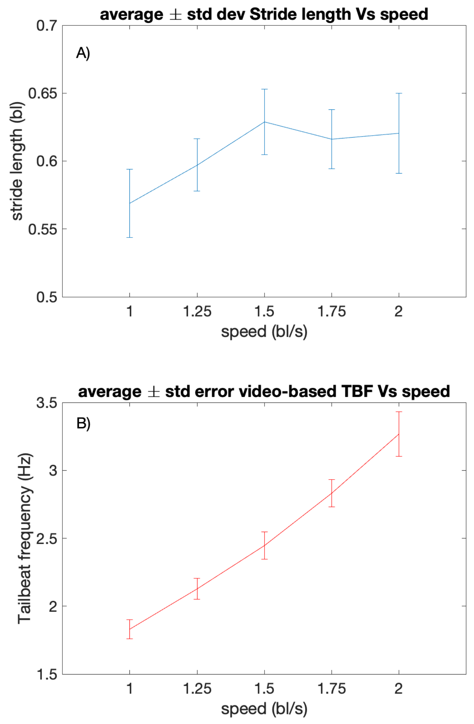
Figure 4A presents the stride length averaged over the six fish at each of the five current speeds between 1 and 2 bl / s . The stride length is presented as a plot of the average (± standard error) stride length measured over the 12 videos for each water speed. The stride lengths are in a range between 0.5   bl to 0.8   bl . According to these results, the measured stride lengths are coherent with the literature [34,35], which indicates that stride length is consistent over various speeds with an average of 0.6   bl .
Figure 4B presents a video-based estimation of TBF (Hz) versus water speed (bl/s) at five water speeds between 1 and 2 bl/s for six fishes. The TBF is presented as a plot of the average (± standard error) TBF measured over the 12 videos for each water speed. Contrary to the observation made for the stride length, video-based TBF estimation is linearly correlated with the speed. This observation indicates that it is more relevant to focus on fish speed than stride length to study TBF.
The following section provides the first results regarding these bioimpedance-based measurements of fish TBF.

4.2. Bioimpedance-Based TBF Estimation in Relation to Swimming Speed

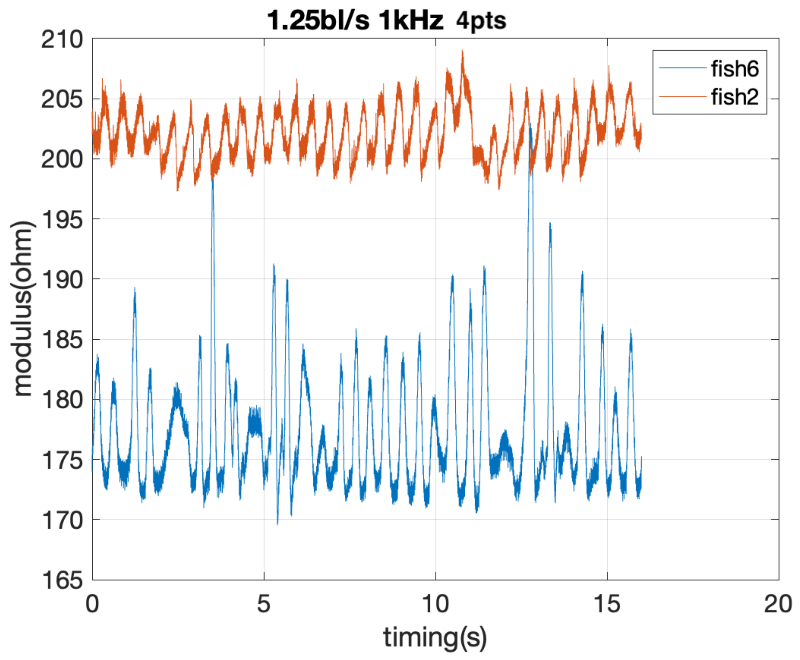
Figure 5 presents the bioimpedance modulus variation during the 16-s measurement for two fish and one measurement setup: water speed at 1.25   bl / s , bioimpedance frequency measurement at 1 k Hz , and for the 4 pt bioimpedance setup. For both fish, the bioimpedance value oscillated. The mean values of the bioimpedance modulus were in the range of 100 to 200 Ω , which is an expected value for biological tissues. In addition, the bioimpedance values had the same oscillation as the fish’s tail. Based on these observations, we assumed that the bioimpedance measurement variation provided some information related to the fish’s movement, in this case the beating of the tail.
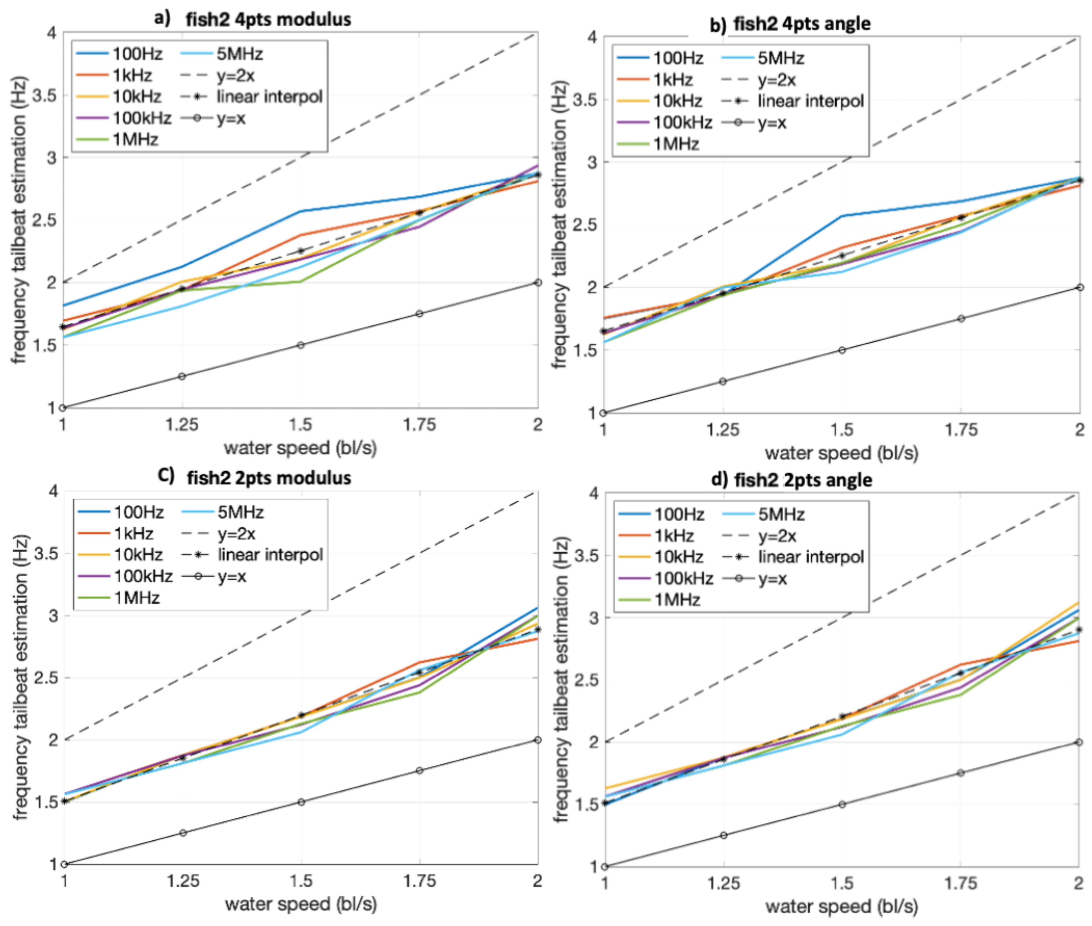
Figure 6 presents the water speed against the estimations of TBF based on the 4 bioimpedance measurements (modulus/4 pts, angle/4 pts, modulus/2 pts, angle/2 pts) for one fish. The linear interpolation of the data y = x and y = 2 x lines are also plotted.
This graphical presentation of representative data for one fish provides a first positive result. Indeed, it clearly appears that there is a linear relationship between the water speed and the fish TBF estimated using bioimpedance whatever, the water speed, the bioimpedance parameter, and the frequency of bioimpedance measurement. To go further in the analysis of the TBF estimation using bioimpedance measurement, some statistical analyses are presented in the following section.

4.3. Fish TBF Measurement, Video versus Bioimpedance

In order to go deeper than for individual graphical analysis of results, statistical analysis of the whole results is presented in this section.

4.3.1. Correlation and Agreement Considering Bioimpedance Setups and Resulting Electrical Parameters

Table 1 provides the results of the agreement analysis between video-based and bioimpedance-based TBF estimation considering the two setups (2 pts, 4 pts) and the four electrical parameters (modulus, angle, real component, imaginary component) of the bioimpedance measurements. Each bioimpedance-based estimation is the mean of the measurements for the six frequencies. The statistical parameters are: r: correlation coefficient, μ : mean of the difference of estimations, ULOA: Bland and Altman upper limit of agreement, LLOA: Bland and Altman lower limit of agreement, t-test h: t-test result, t-test p: t-test p-value, CCC: Concordance Correlation Coefficient, CI1: CCC lower limit of confidence interval, CI2: CCC upper limit of confidence interval.
R Pearson’s correlation coefficient varies between 0.93 and 0.97 , indicating that all the bioimpedance measurements have a strong relationship with video-based TBF estimation. Considering Bland and Altman plot parameters ( μ , ULOA, LLOA), all the measurements have a mean between −0.01 and −0.05 and a 95% limits of agreement range between [ 0.37 , 0.46 ] and [ 0.24 , 0.30 ] . That is, 95% of measurements have an absolute error below 0.46   bl / s for the worst case and below 0.30   bl / s for the best case.
Comparing 4 pts and 2 pts setups, 4 pts have better results for two reasons:
  • All t-tests for 4 pts setup measurements are 1 due to p < 0.01 . For 2 pts setup measurements, the t-test is equal to 0 for real parts and imaginary parts, with p-values of 0.32 and 0.21 .
  • The lowest CCC ( 0.92 and 0.94 ) are for 2 pts setup for modulus and angle electrical parameters. For 4 pts setup, CCC are over 0.96 .
As the results provided in Table 1 are very good overall, we studied the results using not only one electrical parameter but the mean of tail-beat estimations using two or four of them. The objective was to estimate the potential benefit of using electrical parameters that are computed on the same bioimpedance measurement. Each electrical parameter is the average of the measurements for the six frequencies. Table 2 presents the statistical parameter values for the agreement analysis with the following statistical parameters: r: correlation coefficient, μ : mean of the difference of estimations, ULOA: Bland and Altman upper limit of agreement, LLOA: Bland and Altman lower limit of agreement, ttest h: t-test result, t-test p: t-test p-value, CCC: Concordance Correlation Coefficient, CI1: CCC lower limit of confidence interval, CI2: CCC upper limit of confidence interval.
The results are slightly better:
  • r between 0.95 and 0.98 .
  • 95% limits of agreements between [ 0.24 , 0.30 ] and [ 0.31 , 0.41 ] .
  • CCC between 0.94 and 0.97 .
Comparing 2 pts setup to 4 pts one, it still has one t-test equal to 0 and the lowest r ( 0.95 ) and CCC ( 0.94 ).
Figure 7 presents the p-value of the t-test for the eight cases considering 4 pts setup and the eight cases considering 2 pts setup. The 4 pts setup always has a p-value close to 0, as for some parameters (real part, imaginary part) and for one combination of parameters (mean of real part and imaginary part), the p-value is over 0.2 and it consequently doesn’t pass the test. For this reason, in the following analysis we have only considered measurements done in a 4 pt setup. In addition, the two best electrical parameters in terms of r, 95% limits of agreement, and CCC are 4 pts modulus and 4 pts real part. These two electrical parameters are the only ones considered in the following analysis.

4.3.2. Correlation and Agreement Considering Different Frequencies of Bioimpedance Measurement

Table 3 presents the statistical results for the agreement analysis between video-based and bioimpedance-based TBF estimation, considering only 4 pts setup, modulus, and real-part electrical parameters and distinguishing the measurements according to their bioimpedance frequency measurement values.
First of all, real part and modulus have the same results, considering r, μ , ULOA, LLOA, t-test result, and CCC parameters. We can make several observations:
  • The worst results are obtained for freq1 (100 Hz ), with r = 0.93 , 95% limits of agreement [ 0.45 , 0.42 ], t-test results equal to 0, and CCC = 0.92 . Those results are even worse than the ones presented in Table 1 and Table 2.
  • The best results are obtained for freq5 (1 M Hz ), with r = 0.99 , 95% limits of agreement [ 0.12 , 0.20 ], t-test results equal to 1, and CCC = 0.99 . Those results are better than any result from Table 1 and Table 2.
Figure 8 presents the p-value from the t-test according to the frequency of the bioimpedance measurement. It clearly appears that the choice of the frequency has an impact on this result. It must be 10 k Hz or over.

5. Discussion

This study had several purposes. The first was to perform the first bioimpedance measurement on a moving fish. A major concern was the harsh environment. Indeed, due to its composition, seawater has a high conductivity, between 1 S m −1 and 6 S m −1 [36], which is much higher than nominal fish conductivity (700 μ S m −1) [37]. This could have short-circuited the bioimpedance measurement. Based on the bioimpedance values and assuming that their variations were due to fish tailbeat activity, we can conclude that we measured fish bioimpedance. This was because the electrode contacts were oriented towards the inside of the muscle, and the electric field lines lost in the saltwater were limited due to the skin, which acts as an insulator.
The second objective was to explore the use of an implanted bioimpedance electrode to measure TBF by comparing this novel approach against video-based estimations. The agreement analysis demonstrated that this was indeed a valid approach, and, according to the comparative analyses, the best bioimpedance approach was the 4-point setup for modulus impedance measurement at frequencies over 10 k Hz . This can be explained by the fact that the 2-point setup is affected by interface impedance disturbances that were exacerbated by fish activity. The 4-point setup is less impacted by such disturbances. Additionally, interface impedance disturbances behave like a capacitor, which has a diminishing influence as the frequency increases. This explains the benefit of measuring impedance over 10 k Hz .
The experiment was conducted under perfectly controlled conditions, with seabasses swimming in a respirometer at constant speeds. Additionally, bioimpedance measurements were taken over 16 s . To further develop this new method for measurements in freely moving fish, it is necessary to explore:
  • Accuracy using shorter measurement times and more advanced data processing techniques such as Short Time Fast Fourier Transform (STFFT).
  • Response when the fish exhibits unsteady swimming with irregular tailbeats or turns.
Currently, the most widely used solution for estimating TBF in freely moving fish is by accelerometer [8,9,10]. Comparing our approach to accelerometers, the constraints are similar. Our solution requires the implantation of an electrode, while biologgers containing accelerometers need to be implanted in the body cavity [8,10,16] or attached to the back using invasive attachment systems [12]. One of the main reasons for the widespread use of accelerometers is that they are embedded in most electronic tags. This has been possible because accelerometers are commonly embedded in cellphones, making them easy to integrate into electronic devices. The use of our proposed solution remains more difficult as it currently relies on the use of a research-based electrode. However, regarding electronics, it could be integrated into biologgers, as it is already integrated into smartwatches. Indeed, integrated circuits for impedance measurement exist from research domains [38] or as commercial products [39].
A potential advantage of using bioimpedance over an accelerometer is the reduced amount of stored data. Indeed, an accelerometer is not a single sensor but the combination of three sensors measuring acceleration on the three axes of a 3D orthonormal frame. By contrast, the bioimpedance sensor measures a single data stream. To clearly evaluate the potential to reduce memory size for bioimpedance measures compared with accelerometers, it would be necessary to estimate the minimum frequency measurement required. Assuming that the bioimpedance measurement is analyzed using FFT and that the TBF is lower than 4 Hz, according to the Nyquist–Shannon theorem, the sampling rate must be at least twice the bandwidth of the analyzed signal to avoid aliasing. It means that an 8 Hz sample rate would be enough to estimate TBF. Such a sampling frequency is lower than that commonly used for accelerometers in biologgers [8,10,12]. As a consequence, we assume that the amount of data stored using bioimpedance can be at least three times lower than using an accelerometer.
Regarding swimming speed estimation using an accelerometer, [10] highlights a significant drawback. Indeed, swimming speed is estimated using the TBF and the size, which can induce significant errors in speed estimation for long-term studies where the fish can grow significantly. One major benefit of using bioimpedance is its apparent ability to provide a signature directly linked to fish size [40]. Consequently, in addition to fish TBF estimation, bioimpedance measurement enables the estimation of fish length and weight [40]. The dual parameter estimation using bioimpedance has never been demonstrated simultaneously, but it is an exciting perspective that could revolutionize the long-term use of biologgers. Moreover, the bioimpedance signature is strongly linked to any biological process that affects tissue compositions, which leads to various potential applications such as fish condition [41] or fat content [42,43].
As previously mentioned, this experiment is the first one providing bioimpedance measurement on a moving seabass. To go further in the study of the benefits of such an approach, some additional studies are mandatory:
  • There is a need to instrument some fish with a biologger integrating a bioimpedance sensor in order to analyze the sensor response to some various behaviors resulting from free movements, such as burst swim and quick turn.
  • Bioimpedance is known to be sensitive to temperature variations. Regarding TBF estimation using bioimpedance, we hypothesize that it would have only an impact on the signal amplitude, which shouldn’t affect the signal frequency estimation. Any way, a common solution is to integrate a temperature sensor in the electrode and calibrate the measurement according to temperature [44,45]
  • One needed analysis regarding our newly proposed application is the effect of time. In order to be able to apply such an approach over a long time, there is a need for highly reliable electrodes that would resist repeated bendings in a harsh environment.

Author Contributions

Conceptualization, V.K., S.B. (Serge Bernard), S.B. (Sylvain Bonhommeau), T.R., F.S. and D.J.M.; methodology, V.K. and D.J.M.; software, V.K.; validation, V.K., T.R., and D.J.M.; formal analysis, V.K. and D.J.M.; investigation, V.K., M.-M.B., and D.J.M.; resources, V.K. and M.-M.B.; data curation, V.K.; writing—original draft preparation, V.K.; writing—review and editing, T.R. and D.J.M.; visualization, V.K.; supervision, V.K. and D.J.M.; project administration, V.K., S.B. (Serge Bernard), S.B. (Sylvain Bonhommeau) and T.R.; funding acquisition, V.K., S.B. (Serge Bernard), S.B. (Sylvain Bonhommeau), and T.R. All authors have read and agreed to the published version of the manuscript.

Funding

This research was funded by an IFREMER Merlin grant for the POPSTAR project, and this project has been co-funded by the EU through the European Maritime and Fisheries Fund (EMFF) within the National Program for the collection.

Institutional Review Board Statement

Experimental procedures were approved by the ethics committee for animal experimentation n° 036 of the French Ministère de l’Enseignement Superieur, de la Recherche et de l’Innovation, with reference number APAFIS.

Informed Consent Statement

Not applicable.

Data Availability Statement

The raw data supporting the conclusions of this article will be made available by the authors on request.

Acknowledgments

We thank all the staff of Ifremer Aquaculture Research Station in Palavas-les-Flots and particularly Alain Vergnet and Stéphane Lallemand for their cooperation and kind support throughout our experiment.

Conflicts of Interest

The authors declare no conflicts of interest.

Abbreviations

The following abbreviations are used in this manuscript:
2 pts/4 pts2 points/4 points
CCCConcordance Correlation Coefficient
CI1CCC lower limit of confidence interval
CI2CCC upper limit of confidence interval
FFTFast Fourier Transform
freqfrequency
ICCIntraclass Correlation Coefficient
LLOALower Limit of the Interval
modmodulus
STFFTShort Time Fast Fourier Transform
TBFTail-beat Frequency
ULOAUpper Limit of the Interval

References

  1. Videler, J.J. Fish Swimming; Springer: Dordrecht, The Netherlands, 1993. [Google Scholar] [CrossRef]
  2. Webb, P.W. Swimming. In The Physiologuy of Fishes; Evans, D., Ed.; CRC Press: Boca Raton, FL, USA, 1998; pp. 1–38. [Google Scholar]
  3. Bainbridge, R. The Speed of Swimming of Fish as Related to Size and to the Frequency and Amplitude of the Tail Beat. J. Exp. Biol. 1958, 35, 109–133. [Google Scholar] [CrossRef]
  4. Gleiss, A.C.; Schallert, R.J.; Dale, J.J.; Wilson, S.G.; Block, B.A. Direct measurement of swimming and diving kinematics of giant Atlantic bluefin tuna (Thunnus thynnus). R. Soc. Open Sci. 2019, 6, 190203. [Google Scholar] [CrossRef]
  5. Wardle, C.S. Limit of fish swimming speed. Nature 1975, 255, 725–727. [Google Scholar] [CrossRef] [PubMed]
  6. Svendsen, M.B.S.; Domenici, P.; Marras, S.; Krause, J.; Boswell, K.M.; Rodriguez-Pinto, I.; Wilson, A.D.M.; Kurvers, R.H.J.M.; Viblanc, P.E.; Finger, J.S.; et al. Maximum swimming speeds of sailfish and three other large marine predatory fish species based on muscle contraction time and stride length: A myth revisited. Biol. Open 2016, 5, 1415–1419. [Google Scholar] [CrossRef] [PubMed]
  7. Handegard, N.O.; Pedersen, G.; Brix, O. Estimating tail-beat frequency using split-beam echosounders. ICES J. Mar. Sci. 2009, 66, 1252–1258. [Google Scholar] [CrossRef]
  8. Carbonara, P.; Alfonso, S.; Dioguardi, M.; Zupa, W.; Vazzana, M.; Dara, M.; Spedicato, M.T.; Lembo, G.; Cammarata, M. Calibrating accelerometer data, as a promising tool for health and welfare monitoring in aquaculture: Case study in European sea bass (Dicentrarchus labrax) in conventional or organic aquaculture. Aquac. Rep. 2021, 21, 100817. [Google Scholar] [CrossRef]
  9. Cade, D.E.; Barr, K.R.; Calambokidis, J.; Friedlaender, A.S.; Goldbogen, J.A. Determining forward speed from accelerometer jiggle in aquatic environments. J. Exp. Biol. 2018, 221, jeb170449. [Google Scholar] [CrossRef]
  10. Warren-Myers, F.; Svendsen, E.; Føre, M.; Folkedal, O.; Oppedal, F.; Hvas, M. Novel tag-based method for measuring tailbeat frequency and variations in amplitude in fish. Anim. Biotelemetry 2023, 11, 12. [Google Scholar] [CrossRef]
  11. McKenzie, D.J.; Axelsson, M.; Chabot, D.; Claireaux, G.; Cooke, S.J.; Corner, R.A.; De Boeck, G.; Domenici, P.; Guerreiro, P.M.; Hamer, B.; et al. Conservation physiology of marine fishes: State of the art and prospects for policy. Conserv. Physiol. 2016, 4, cow046. [Google Scholar] [CrossRef]
  12. Clarke, T.M.; Whitmarsh, S.K.; Hounslow, J.L.; Gleiss, A.C.; Payne, N.L.; Huveneers, C. Using tri-axial accelerometer loggers to identify spawning behaviours of large pelagic fish. Mov. Ecol. 2021, 9, 26. [Google Scholar] [CrossRef]
  13. Kawabata, Y.; Noda, T.; Nakashima, Y.; Nanami, A.; Sato, T.; Takebe, T.; Mitamura, H.; Arai, N.; Yamaguchi, T.; Soyano, K. Use of a gyroscope/accelerometer data logger to identify alternative feeding behaviours in fish. J. Exp. Biol. 2014, 217, 3204–3208. [Google Scholar] [CrossRef]
  14. Broell, F.; Taylor, A.D.; Litvak, M.K.; Bezanson, A.; Taggart, C.T. Post-tagging behaviour and habitat use in shortnose sturgeon measured with high-frequency accelerometer and PSATs. Anim. Biotelemetry 2016, 4, 11. [Google Scholar] [CrossRef]
  15. Cruz-Font, L.; Shuter, B.J.; Blanchfield, P.J. Energetic costs of activity in wild lake trout: A calibration study using acceleration transmitters and positional telemetry. Can. J. Fish. Aquat. Sci. 2016, 73, 1237–1250. [Google Scholar] [CrossRef]
  16. Zupa, W.; Alfonso, S.; Gai, F.; Gasco, L.; Spedicato, M.T.; Lembo, G.; Carbonara, P. Calibrating Accelerometer Tags with Oxygen Consumption Rate of Rainbow Trout (Oncorhynchus mykiss) and Their Use in Aquaculture Facility: A Case Study. Animals 2021, 11, 1496. [Google Scholar] [CrossRef] [PubMed]
  17. Bouyoucos, I.A.; Montgomery, D.W.; Brownscombe, J.W.; Cooke, S.J.; Suski, C.D.; Mandelman, J.W.; Brooks, E.J. Swimming speeds and metabolic rates of semi-captive juvenile lemon sharks (Negaprion brevirostris, Poey) estimated with acceleration biologgers. J. Exp. Mar. Biol. Ecol. 2017, 486, 245–254. [Google Scholar] [CrossRef]
  18. Grimnes, S.; Martinsen, Ø.G. (Eds.) Chapter 1—Introduction. In Bioimpedance and Bioelectricity Basics, 3rd ed.; Academic Press: Oxford, UK, 2015; pp. 1–7. [Google Scholar] [CrossRef]
  19. Khalil, S.F.; Mohktar, M.S.; Ibrahim, F. The Theory and Fundamentals of Bioimpedance Analysis in Clinical Status Monitoring and Diagnosis of Diseases. Sensors 2014, 14, 10895–10928. [Google Scholar] [CrossRef]
  20. Willis, J.; Hobday, A.J. Application of bioelectrical impedance analysis as a method for estimating composition and metabolic condition of southern bluefin tuna (Thunnus maccoyii) during conventional tagging. Fish. Res. 2008, 93, 64–71. [Google Scholar] [CrossRef]
  21. Zaniboni-Filho, E.; Hermes-Silva, S.; Weingartner, M.; Jimenez, J.E.; Borba, M.R.; Fracalossi, D.M. Bioimpedance as a tool for evaluating the body composition of suruvi (Steindachneridion scriptum). Braz. J. Biol.-Rev. Bras. Biol. 2015, 75. [Google Scholar] [CrossRef]
  22. Mesa, M.G.; Rose, B.P. An assessment of morphometric indices, blood chemistry variables and an energy meter as indicators of the whole body lipid content in Micropterus dolomieu, Sander vitreus and Ictalurus punctatus. J. Fish Biol. 2015, 86, 755–764. [Google Scholar] [CrossRef]
  23. Hafs, A.W.; Hartman, K.J. Developing bioelectrical impedance analysis methods for age-0 brook trout. Fish. Manag. Ecol. 2014, 21, 366–373. [Google Scholar] [CrossRef]
  24. Khramtsova, N.I.; Plaksin, S.A. Two-electrode bioelectrical impedance measurement in body composition analysis before and after liposuction. In Proceedings of the 2016 IEEE International Symposium on Medical Measurements and Applications (MeMeA), Benevento, Italy, 15–18 May 2016; pp. 1–5. [Google Scholar] [CrossRef]
  25. Robert, M.; Dagorn, L.; Bodin, N.; Pernet, F.; Arsenault-Pernet, E.J.; Deneubourg, J.L. Comparison of condition factors of skipjack tuna (Katsuwonus pelamis) associated or not with floating objects in an area known to be naturally enriched with logs. Can. J. Fish. Aquat. Sci. 2014, 71, 472–478. [Google Scholar] [CrossRef]
  26. Blanco-Almazán, D.; Groenendaal, W.; Catthoor, F.; Jané, R. Chest Movement and Respiratory Volume both Contribute to Thoracic Bioimpedance during Loaded Breathing. Sci. Rep. 2019, 9, 20232. [Google Scholar] [CrossRef] [PubMed]
  27. Detrez, E.; Kerzérho, V.; Belhaj, M.M.; Vergnet, A.; de Verdal, H.; Rouyer, T.; Bonhommeau, S.; Lamlih, A.; Julien, M.; Ben Ali, F.; et al. Study differentiating fish oocyte developmental stages using bioimpedance spectroscopy. Aquaculture 2022, 547, 737396. [Google Scholar] [CrossRef]
  28. Ranganathan, P.; Pramesh, C.S.; Aggarwal, R. Common pitfalls in statistical analysis: Measures of agreement. Perspect. Clin. Res. 2017, 8, 187. [Google Scholar] [CrossRef] [PubMed]
  29. Watson, P.; Petrie, A. Method agreement analysis: A review of correct methodology. Theriogenology 2010, 73, 1167–1179. [Google Scholar] [CrossRef]
  30. Martin Bland, J.; Altman, D. Statistical Methods for Assessing Agreement between Two Methods of Clinical Measurement. Lancet 1986, 327, 307–310. [Google Scholar] [CrossRef]
  31. Rik. BlandAltmanPlot. 2021. Available online: https://fr.mathworks.com/matlabcentral/fileexchange/71052-blandaltmanplot/ (accessed on 19 September 2023).
  32. Lin, L.I.K. A Concordance Correlation Coefficient to Evaluate Reproducibility. Biometrics 1989, 45, 255–268. [Google Scholar] [CrossRef]
  33. Matthew, R. f_CCC. 2018. Available online: https://fr.mathworks.com/matlabcentral/fileexchange/66896-f_ccc (accessed on 19 September 2023).
  34. Georgopoulou, D.G.; Stavrakidis-Zachou, O.; Mitrizakis, N.; Papandroulakis, N. Tracking and Analysis of the Movement Behavior of European Seabass (Dicentrarchus labrax) in Aquaculture Systems. Front. Anim. Sci. 2021, 2, 754520. [Google Scholar] [CrossRef]
  35. Marras, S.; Killen, S.S.; Domenici, P.; Claireaux, G.; McKenzie, D.J. Relationships among Traits of Aerobic and Anaerobic Swimming Performance in Individual European Sea Bass Dicentrarchus labrax. PLoS ONE 2013, 8, e72815. [Google Scholar] [CrossRef]
  36. Tyler, R.H.; Boyer, T.P.; Minami, T.; Zweng, M.M.; Reagan, J.R. Electrical conductivity of the global ocean. Earth Planets Space 2017, 69, 156. [Google Scholar] [CrossRef]
  37. Kolz, A.L. Electrical Conductivity as Applied to Electrofishing. Trans. Am. Fish. Soc. 2006, 135, 509–518. [Google Scholar] [CrossRef]
  38. Lamlih, A.; Freitas, P.; Belhaj, M.M.; Salles, J.; Kerzérho, V.; Soulier, F.; Bernard, S.; Rouyer, T.; Bonhommeau, S. A Hybrid Bioimpedance Spectroscopy Architecture for a Wide Frequency Exploration of Tissue Electrical Properties. In Proceedings of the 2018 IFIP/IEEE International Conference on Very Large Scale Integration (VLSI-SoC), Verona, Italy, 8–10 October 2018; pp. 168–171. [Google Scholar] [CrossRef]
  39. Analog Devices Impedance Measurement Products List. Available online: https://www.analog.com/en/solutions/instrumentation-and-measurement/electronic-test-and-measurement/impedance-measurement-and-analysis.html (accessed on 29 September 2024).
  40. Kerzérho, V.; Azaïs, F.; Bernard, S.; Bonhommeau, S.; Brisset, B.; De Knyff, L.; Julien, M.; Renovell, M.; Rouyer, T.; Saraux, C.; et al. Multilinear Regression Analysis between Local Bioimpedance Spectroscopy and Fish Morphological Parameters. Fishes 2023, 8, 88. [Google Scholar] [CrossRef]
  41. Hartman, K.J.; Margraf, F.J.; Hafs, A.W.; Cox, M.K. Bioelectrical Impedance Analysis: A New Tool for Assessing Fish Condition. Fisheries 2015, 40, 590–600. [Google Scholar] [CrossRef]
  42. Pothoven, S.A.; Ludsin, S.A.; Höök, T.O.; Fanslow, D.L.; Mason, D.M.; Collingsworth, P.D.; Van Tassell, J.J. Reliability of Bioelectrical Impedance Analysis for Estimating Whole-Fish Energy Density and Percent Lipids. Trans. Am. Fish. Soc. 2008, 137, 1519–1529. [Google Scholar] [CrossRef]
  43. Duncan, M.; Craig, S.R.; Lunger, A.N.; Kuhn, D.D.; Salze, G.; McLean, E. Bioimpedance assessment of body composition in cobia Rachycentron canadum (L. 1766). Aquaculture 2007, 271, 432–438. [Google Scholar] [CrossRef]
  44. Ruiz-Vargas, A.; Ivorra, A.; Arkwright, J.W. Design, Construction and Validation of an Electrical Impedance Probe with Contact Force and Temperature Sensors Suitable for in-vivo Measurements. Sci. Rep. 2018, 8, 14818. [Google Scholar] [CrossRef]
  45. Leung, T.K.W.; Ji, X.; Peng, B.; Chik, G.K.K.; Dai, D.S.H.S.; Fang, G.; Zhang, T.; Cheng, X.; Kwok, K.W.; Tsang, A.C.O.; et al. Micro-electrodes for in situ temperature and bio-impedance measurement. Nano Select 2021, 2, 1986–1996. [Google Scholar] [CrossRef]
Figure 1. 4-point and 2-point bioimpedance measurement set-ups.
Fishes 09 00399 g001
Figure 2. (A) The flexible biocompatible 4-contact electrode for bioimpedance measurement; (B) Fish after surgery for implantation of the electrode; (C) post-surgery fish recovery in the Steffensen-type swim tunnel.
Fishes 09 00399 g002
Figure 3. Sequential timing description of one bioimpedance measurement series.
Fishes 09 00399 g003
Figure 4. (A) stride length ( bl ) versus water speed ( bl / s ), (B) video-based estimation of TBF ( Hz ) versus water speed ( bl / s ) at 5 water speeds.
Fishes 09 00399 g004
Figure 5. Plotter graph example: variation of the modulus of the bioimpedance over the 16 s measurement for two fishes. The water speed is 1.25 bl/s, the bioimpedance measurement setup is 4 pts, and the bioimpedance frequency measurement is 1 k Hz .
Fishes 09 00399 g005
Figure 6. Water speed versus bioimpedance-based TBF estimation for fish 2 (a) 4 pts modulus of bioimpedance for frequency estimation; (b) 4 pts angle of bioimpedance for frequency estimation; (c) 2 pts modulus of bioimpedance for frequency estimation, (d) 2 pts angle of bioimpedance for frequency estimation.
Fishes 09 00399 g006
Figure 7. t-test p-value for the 4 pts and 2 pts setups and eight combinations of electrical parameters.
Fishes 09 00399 g007
Figure 8. t-test p-value for the 4 pts setup, two electrical parameters, and six bioimpedance frequencies.
Fishes 09 00399 g008
Table 1. Statistical analysis results bioimpedance-based estimation of TBF for the two setups (4 pts yellow, 2 pts red) and the four electrical parameters (mod, angle, real, imag).
Bioimpedance Setup and Parameterr μ ULOALLOAt-Testt-Test pCCCCI1CI2
4 pts mod0.97−0.030.24−0.30100.970.960.98
4 pts angle0.97−0.030.26−0.3210.010.960.950.97
2 pts mod0.95−0.060.29−0.39100.940.920.96
2 pts angle0.93−0.050.37−0.4610.010.920.890.94
4 pts real0.97−0.030.24−0.3010.010.970.960.98
4 pts imag0.97−0.030.26−0.3210.010.960.950.97
2 pts real0.97−0.010.26−0.2900.320.970.950.97
2 pts imag0.96−0.020.29−0.3300.210.960.940.97
Table 2. Statistical analysis results, bioimpedance-based estimation of TBF for the two setups (4 pts yellow, 2 pts red), and the mean of two to four electrical parameters.
Bioimpedance Setup and Mean of Parametersr μ ULOALLOAt-Testt-Test pCCCCI1CI2
4 pts mean (mod, angle)0.98−0.030.24−0.3010.010.970.960.98
4 pts mean (real, imag)0.97−0.030.24−0.3010.010.970.960.98
4 pts mean (mod, real)0.97−0.030.24−0.3010.010.970.960.98
4 pts mean (mod, angle, real, imag)0.97−0.030.24−0.3010.010.970.960.98
2 pts mean (mod, angle)0.95−0.050.31−0.41100.940.910.95
2 pts mean (real, imag)0.97−0.010.27−0.3000.240.960.950.97
2 pts mean (mod, real)0.97−0.030.24−0.30100.960.950.97
2 pts mean (mod, angle, real, imag)0.97−0.030.25−0.3110.010.960.950.97
Table 3. Statistical analysis results (r: correlation coefficient, μ : mean of the difference of estimations, ULOA: Bland and Altman upper limit of agreement, LLOA: Bland and Altman lower limit of agreement, ttest h: t-test result, ttest p: t-test p-value, CCC: Concordance Correlation Coefficient, CI1: CCC lower limit of confidence interval, CI2: CCC upper limit of confidence interval), bioimpedance-based estimation of TBF for the two setups (4 pts yellow, 2 pts red), two electrical parameters (mod and real) and each of the 6 bioimpedance frequencies (100 Hz , 1 k Hz , 10 k Hz , 100 k Hz , 1 M Hz , 5 M Hz ).
Bioimpedance Setup, Parameter and Frequency Numberr μ ULOALLOAt-Testt-Test pCCCCI1CI2
4 pts mod freq10.930.010.45−0.4200.790.920.840.96
4 pts mod freq20.98−0.020.27−0.3100.440.970.940.98
4 pts mod freq30.99−0.050.13−0.2310.010.980.960.99
4 pts mod freq40.98−0.050.19−0.2900.060.970.940.99
4 pts mod freq50.99−0.040.12−0.2010.020.990.970.99
4 pts mod freq60.99−0.050.15−0.2410.030.980.960.99
2 pts mod freq10.930.010.45−0.4200.780.920.840.96
2 pts mod freq20.98−0.020.27−0.3100.440.970.940.98
2 pts mod freq30.98−0.050.13−0.2310.010.980.960.99
2 pts mod freq40.98−0.050.19−0.2900.060.970.940.99
2 pts mod freq50.99−0.040.12−0.2010.020.990.970.99
2 pts mod freq60.99−0.050.15−0.2410.030.980.960.99
Disclaimer/Publisher’s Note: The statements, opinions and data contained in all publications are solely those of the individual author(s) and contributor(s) and not of MDPI and/or the editor(s). MDPI and/or the editor(s) disclaim responsibility for any injury to people or property resulting from any ideas, methods, instructions or products referred to in the content.