Article

MRI Robot for Prostate Focal Laser Ablation: An Ex Vivo Study in Human Prostate

1
Center for Interventional Oncology, National Institutes of Health (NIH), Bethesda, MD 20814, USA
2
Department of Mechanical Engineering, University of Arkansas, Fayetteville, AR 72701, USA
3
School of Electrical and Computer Engineering, University of Georgia, Athens, GA 30602, USA
*
Author to whom correspondence should be addressed.
J. Imaging 2018, 4(12), 140; https://doi.org/10.3390/jimaging4120140
Submission received: 15 September 2018 / Revised: 30 October 2018 / Accepted: 22 November 2018 / Published: 29 November 2018
(This article belongs to the Special Issue Image-Guided Medical Robotics)

Abstract

:
Purpose: A novel grid-template-mimicking MR-compatible robot was developed for in-gantry MRI-guided focal laser ablation of prostate cancer. Method: A substantially compact robot was designed and prototyped to meet in-gantry lithotomy ergonomics and allow for accommodation in the perineum. The controller software was reconfigured and integrated with the custom-designed navigation and multi-focal ablation software. Three experiments were conducted: (1) free space accuracy test; (2) phantom study under computed tomography (CT) guidance for image-guided accuracy test and overall workflow; and (3) magnetic resonance imaging (MRI)-guided focal laser ablation of an ex vivo prostate. The free space accuracy study included five targets that were selected across the workspace. The robot was then commanded five times to each target. The phantom study used a gel phantom made with color changing thermos-chromic ink, and four spherical metal fiducials were deployed with the robot. Then, laser ablation was applied, and the phantom was sliced for gross observation. For an MR-guided ex vivo test, a prostate from a donor who died of prostate cancer was obtained and multi-focally ablated using the system within the MRI gantry. The tissue was sliced after ablation for validation. Results: free-space accuracy was 0.38 ± 0.27 mm. The overall system targeting accuracy under CT guidance (including robot, registration, and insertion error) was 2.17 ± 0.47 mm. The planned ablation zone was successfully covered in both acrylamide gel phantom and in human prostate tissue. Conclusions: The new robot can accurately facilitate fiber targeting for MR-guided focal laser ablation of targetable prostate cancer.

1. Introduction

Prostate cancer (PCa) is the most common cancer in men and is the second leading cause of cancer-related deaths in the United States with an estimated 169,000 new cases and 28,000 deaths in 2018 [1]. Many PCa patients have low or intermediate risk and organ-confined cancer, making them potential candidates for active surveillance and/or focal therapy [2]; however, the long-term efficacy of focal therapies is still being defined and refined. Focal laser ablation (FLA) (Figure 1a) is one form of focal therapy which uses a high-energy laser to cause cell death through rapid heating at the targeted region, resulting in a well-controlled ablation zone with a tight transition zone, which leaves the rest of the organ un-injured. Other less focal ablation modalities or more invasive options, such as surgical removal, may result in side effects such as impotence and incontinence. Thermal ablation is aided by accurate temperature monitoring. Currently, the only imaging modality that can provide accurate real-time thermometry is MRI. Laser ablation is an inherently MRI-safe technique as it introduces only non-magnetic optical fibers into the tissue. Visualase™ (Medtronic, Dublin, Ireland) laser ablation system (Figure 1b) is a US Food and Drug Administration (FDA) cleared device for minimally invasive ablation, with applications in neurosurgery and urology, such as deep brain lesioning or prostate focal therapy [3]. The laser machine, navigation system, and cooling pump are placed outside the MRI room and the fiber and cooling tubes are passed through the conduit connecting the MRI room and the control room. With the standard commercial approach, the laser fiber is guided using a grid template (with embedded MR markers (Figure 1a). However, the current commercially available FLA system and MRI software for PCa treatment has some limitations: (1) the positioning resolution is limited to the distance between the holes on the grid template (typically 5 mm); (2) the grid does not offer an angulated needle path, which may be necessary in some patients with lesions obscured by pubic arch; (3) the workflow is not efficient, requiring the patient be moved in-and-out of the gantry multiple times following adjustments. This contributes to increased MR scanning times and procedure costs; and (4) the navigation and treatment planning software does not always offer user-friendly multi-focal composite ablation planning nor 3D temperature monitoring fused to relevant MRI anatomic sequences.
Robot-assisted in-gantry needle guidance has theoretical and proven advantages over the grid template. This needle guidance can offer: submillimeter positioning resolution, autonomous needle targeting, needle angulation, improvement of the workflow, reduction of the MR time [4,5,6,7,8], and remote needle insertion and steering [9]. In particular, Stoianovici et al. introduced an MRI-safe transrectal prostate biopsy robot and tested it in animal [4]. Fischer et al. presented a pneumatic cylinder actuator based robot for a MRI-guided transperineal prostate biopsy [5]. Krieger et al. introduced an MRI-compatible robotic system for transrectal prostate interventions [6]. Song et al. reported a pneumatic robot for MRI-guided transperineal prostate biopsy [7]. Goldenberg et al. developed a novel closed-bore robotic system for MRI-guided transperineal prostatic interventions [8]. Seifabadi et al. reported a teleoperated needle steering robotic system for in-gantry prostate biopsy [9]. Monfaredi et al. have reviewed thoroughly the state of the art MRI-guided needle intervention robots [10]. The abovementioned robots had been designed mainly for prostate biopsy. Cepek et al. developed a manually controlled four-degrees of freedom (DoF) transperineal mechanism for needle alignment for FLA under MRI-guidance [3] with a median guidance error of 3.5 mm in 10 patients. This is perhaps the first try to use a mechatronic device to assist physicians during FLA. Previously, we proposed a two-DoF template-mimicking MR conditional robot for PCa FLA and tested it on an anatomical prostate phantom [11] and canine cadaver [12]. After those preliminary studies, it was concluded that the robot foot-print is too large and needed to be scaled-down for human testing. Therefore, the first contribution of this paper is to redesign and prototype the robot in order to reduce its size, so it can be comfortably accommodated between the patient’s legs while in lithotomy position, inside the MR gantry. Secondly, the robot controller was initially implemented in Labview and was separate from the navigation and ablation monitoring software. In the updated integrated version, the controller software was developed in C++ and was embedded into the custom software (OncoNav, NIH, Bethesda, USA). Therefore, navigation, control, and ablation planning and monitoring were all performed in one integrated software platform, allowing the user to have full control of the operation of the robot and ablation margin creation. The robot’s accuracy in targeting, as well as the feasibility in ablation, was tested in a thermochromic phantom under CT guidance. Finally, the feasibility of MR-guided multi-focal laser ablation was then tested in a human ex vivo prostate tissue from a donor with prostate cancer.

2. Materials and Methods

2.1. System Overview

A MRI-guided robot assisted focal laser ablation system consisted of the following four components (Figure 2): (1) robotic system, which included the custom robot, robot controller hardware, and an air pump; (2) standard 3T MRI, for navigation, targeting, and temperature monitoring; (3) custom navigation, planning, and controller software, multi-focal laser ablation software and ablation monitoring all embedded in a custom-developed software called “OncoNav”, which runs on a PC; and (4) standard laser ablation system including the laser generator, optical fibers, laser sheath, foot pedals, a cooling catheter, and a water pump. A MR-compatible monitor facilitates in room review navigation, monitoring, and verification.
To minimize the number of components that were required to be MR compatible, the robot controller hardware, the air pump, the PC that runs OncoNav, the laser generator, and the cooling pump, were all placed in the control room. Only the robot and the laser sheath were placed on the MRI table inside the MRI room. A cable bundle that included air tubes and optical fibers for robot encoders, the optical fibers for the laser ablation, the cooling water tubes, and anesthesiology tube (during in vivo study) were all passed through a conduit tube (waveguide) that connects the controller room to the MRI room. The following sections outline details of the different components.

2.2. The Robotic System

The robotic system included the robot hardware, the controller hardware and software, and an air pump.

2.2.1. Robot

The robot is shown in Figure 3a and it included a template mimicking CoreXY stage [13] shown in Figure 3c. The CoreXY stage guided the needle automatically toward a target selected by the physician from the preoperative MR image, and the physician then inserted the needle manually, thereby the physician was in a full control of the procedure while avoiding the burden of needle guidance. In the current design, the width of the robot was reduced by 40 mm (from 130 to 90 mm) in comparison to the previous design [12]; however, the height was the same as the original design (180 mm). Despite downsizing the robot’s footprint, the overall robot workspace was kept the same as the previous design (53 mm × 90 mm). The desired workspace is based on a grid template which is used during prostate biopsy or brachytherapy (typically 65 × 65 mm).
To achieve this, we did the following: (1) removed the motors shafts toward each other. (2) We then use new pneumatic motors that are more compact. For this purpose, we redesigned and 3D printed the housing of the air motor (Figure 3b). (3) removed the guide rail that supports the MR coil holder and moved it to the top (Figure 3a). Then, we 3D printed all components, and rebuilt the robot. The robot kinematics however is still the same. The robot had two translational DoF, left-right and up-down. Two custom designed MRI-conditional pneumatic motors with built-in optical encoders were mounted on the top of the CoreXY frame to actuate the template [13]. As illustrated in Figure 3c, the template position was coupled with the rotational position of the two motors, which can be expressed by the following equation:
ΔX = 1/2(ΔA + ΔB),
ΔY = 1/2(ΔA − ΔB),
where ΔX and ΔY are the displacement of the template, respectively, and ΔA and ΔB are the motor rotational position.
Compared to the motors reported in [14], two upgrades have been applied: (1) the motor has become more compact; and (2) the number of transmitters/receivers for optical encoding has increased from one pair to two, for redundant measurements and optimized accuracy. On the external of the of the motor housing (cap and body), extensions were added to allow the motor casing to be assembled independently of affixation to the gearbox and robot, assuring the robustness of the motor as an independent unit. Motor encoding was improved by integrating a pair of interruption-based fiber optic lines, which allowed quadrature encoding and a higher degree of reliability for the encoding. The cap was extended to allow a pair of stacked fiber optic cables to be inserted, while an extension on the rotor supported the asymmetric interrupters, which blocked transmission of the optical signal. Figure 4 shows the motor CAD design.
Two sets of belts, red and blue lines in Figure 3c, transfer the motor rotational motion to template translational DoF. To move the template in the X-direction, the motor rotational motion should be the same in both direction and magnitude. Similarly, template Y-direction motion can be produced by running the two motors in the opposite direction with the same magnitude. Moving one motor could generate the template diagonal motion in ±45°, as can be seen in Equation (1). The robot can be easily mounted on the holder (Figure 3a) which is attached to a rotating arm which is pivoted to the robot base plate using a ceramic bearing (Figure 3d). The rotating arm DoF pivots the robot about the approximate location of the prostate, providing 0°, ±7.5° and ±15° relative to 0° parallel to the axis of the bore. This permits the targeting of tumors obstructed by the pubic bone, which may occur in a straight needle trajectory scenario for the right or left lateral part of the prostate. The rotating arm is manually moved and is not actuated as it is used occasionally. Although not clinically significant, the end-effector speed is 3 mm/s.
Most of the robot components were made out of plastic (P430 ABS plus, StrataSys, Eden Prairie, MN, USA, MN—tensile strength: 33 MPa), using a 3D printer (StrataSys, Eden Prairie, MN, USA). The robot also included brass rods and belt guides. The shaft of the motor was made from brass to increase strength under the load applied by the timing belt. Six sets of planetary gear boxes (Tamiya, Shizuoka, Japan) were utilized for each air-motor to reduce the speed and increase the torque. A removable plate was considered at the top of the CoreXY robot to protect the motors from the pressure applied by the imaging coil. The robot and rotating arm was installed on a double layer of 0.375” thick acrylic sheet.
The robot was registered to the MRI coordinate system by MR visible markers as showed in Figure 5a.
Five fiducial markers (D = 6 mm, Beekley Inc., Bristol, CT, USA) were precisely located at the predefined positions on the transverse plane of the robot. All markers are located on a single plane because the robot end-effector only moves in a plane parallel to this plane. Prior to navigation and planning, high-resolution scanning was conducted to locate the fiducial markers’ positions in the imaging coordinate system. The fiducial markers were located 50 mm away to avoid any potential interference with the brass guiding rod. Since the fiducial markers’ positions in the robot coordinate and MR coordinate were known, registration could be accomplished with the rigid transformation method. The basic principle of this algorithm can be written as the following equation:
A = R × B + t,
where A was the marker position in the robot frame, B was the marker position in the MR image frame, R was the rotation matrix, and t was the translation vector. In this study, we chose the Landmark-Least Squares Method to get the optimal R and t [15]. Although three markers is theoretically sufficient to define R and t, we chose 5 to increase the accuracy. It should be noted that the registration needs to be updated after each time that the rotating arm is rotated.

2.2.2. Controller

Figure 5b shows the controller box, which contained 4 solenoid valves (two per motor–1/4 Inch Electric Air Water Solenoid Valve, WIC Valve, San Jose, CA, USA) that were controlled by a 4 custom developed driver. Two custom-developed circuit boards interpreted the signal coming from the optical encoders to close the control loop. The controller box also had 4 air tubes and 8 optical fibers attached to it. The valves connecting to the 4 air tubes are normally closed, and opened when a command came from the controller. A PC-based measurement and control system (NI USB 6009, National Instrument, Austin, TX, USA) was used both as a DAQ system and a controller, thus enabling the PC to receive the position signals from encoders, compute the control law, and send commands to the valves. A 2.0-Gal. air pump (2010ALFC Ultra Quiet, California Air Tools, San Diego, CA, USA) was used, and the air pressure was set to 100 psi. An 8 m long air tube connected the air pump to the robot controller. Lastly, a safety stop button was implemented for an emergency.
The controller architecture was achieved via the proportional integral (PI) algorithm. The robot inverse kinematics (Equation (1)) calculated the desired motor motion (θ𝑑) according to the relationship between the moving frame current position and the desired position. The custom designed optical encoder provided motor rotational position (θ) to the control loop. Based on the difference between θ𝑑 and θ, the PI controller applied a constant voltage to power the pneumatic valves, which regulated the pneumatic air flow supplied to the motor. This continued until the error falls within a certain threshold at which point, the voltage dropped to zero.
The robot controller software was originally implemented in Labview (National Instrument, Austin, TX, USA). The new version implements in C++, in order to use the navigation and planning software in OncoNav to directly command the robot. An existing API was utilized to enable communication of the visual studio and the DAQ/controller hardware.

2.3. OncoNav Is a Software Platform Used for Navigation, Robot Control, and Ablation Multi-Focal Planning and Monitoring

Targeting: Once the registration was done, the suspicious target identified by an expert radiologist from a pre-operative image was localized on the intra-operative image by the operator. The coordinates of the target in MR were converted to the robot’s coordinate system and were sent to the robot’s controller. The robot moved to the target and waited for the user to insert the needle to the depth calculated by the software.
Iterative Treatment Planning: Prior to ablation, the optimal treatment plan was calculated by minimizing the number of catheter insertions to cover the entire tumor volume. The VisualaseTM Laser Ablation System was used in this study. Ablation size was limited to be within 5–8 mm around the catheter, which required multiple ablations to treat a large tumor. The laser ablation zone has the shape of an elongated ellipsoid, which can be formulated as follows:
(x/p)2 + (y/p)2 + (z/q)2 = 1,
where p and q (normally q > p) are semi-axes lengths. The size of the ablation zone (x, y and z parameters in Equation (3)) is a function of ablation time. Since the prostate does not have major blood vessels, the heat sink effect is small, making the ablation zone highly predictable.
The estimated ablation result through the intraoperative temperature map can be used to update the original treatment plan. The treatment plan was iteratively updated until all the residual tumor was covered. The target was obtained by subtracting the estimated model from the preoperative tumor model after each ablation. The spatial information of the target can be derived from the T2w volumetric image and registered to the robot coordinate frame, which was used for robot joint space motion calculation. Once the needle was inserted to the desired position, another T2w scan was performed to verify its position with respect to the target. Reinsertion or repositioning is performed sequentially until the tumor is fully treated, defined by tumor target margin coverage.

2.4. Typical Workflow

During a procedure, the subject is positioned within the MRI unit throughout the therapy in a lithotomy position. A T2w imaging volume containing the robotic platform and the prostate gland is taken to get the position of the fiducial markers and the targets. Based on the fiducial markers’ positions in the MR image and robot frame, the transformation matrix is derived to map the points in the MR coordinate system to the robot coordinate frame. Two extra MR visible markers are embedded into the funnel shape needle entry (attached to the end effector, Figure 3b) to define the initial robot position (x and y). The robot inverse kinematics calculates the desired motion of each motor and ensured that the center of the targeted tumor is located inside the workspace of moving template. The needle depth is calculated based on the offset of the robot end effector and the target location. Then the physician manually inserts the needle to the desired depth after reviewing the needle insertion trajectory with OncoNav. Then, the laser catheter is inserted and the FLA was performed by delivering the laser energy to the targeted area. The real-time temperature of the position of the ablation catheter is monitored by the OncoNav software. Postoperative images are then compared to the preoperative image to identify the ablated tissue within the tumors.

2.5. Experiments

Free space Accuracy was tested before testing the new robot in gantry. There were 5 targets, 4 at the corners and one in the center and it was targeted 5 times starting from 1 to 5.
A Phantom Study under CT guidance was performed to study the entire workflow, the robot’s accuracy, and the ablation planning and surgical workflow. The system was initially tested prior to the MRI experiment in the CT room. Figure 6 shows the experimental setup.
An acrylamide thermochromic gel phantom was made inside a cylindrical container (D = 100 mm, L = 120 mm). Details of how to make the acrylamide gel can be found in [16]; briefly, an aqueous solution of 40% (w/v) acrylamide/bis-acrylamide (VWR Int. Bridgeport, NJ, USA) with feed ratio (acrylamide to bis-acrylamide) of 19:1 (52.8 mL) was mixed under magnetic stirring with ammonium persulfate (APS, 0.46 g, Sigma Aldrich, St. Louis, MO, USA) to initiate polymerization and degassed, de-ionized water (231.1 mL). This was followed by the addition of Kromagen Magenta MB60-NH concentrate (15.1 mL, TCR Hallcrest, Glenview, IL, USA). Finally, N,N,N′,N′-tetramethylethylenediamine (0.46 mL, Sigma Aldrich, St. Louis, MO, USA) was added as catalyst. The final solution was immediately transferred to a cylindrical container with desired size and kept in a cold room (4 °C) overnight. If polymerization occurs at room temperature, the temperature of the phantom material rises due to the heat of the polymerization process [17] thereby imparting unwanted color change to the phantom. Therefore, it is important to allow the phantom material to slowly polymerize at 4 °C, to avoid undesired and confounding color changes. The gel changed its color from pale yellow to pink when heated above 55 °C. There were 4 spherical metal markers embedded inside the phantom at 4 different locations and depths. Two of the markers were 2 mm in diameter and the other two had the diameter of 0.5 mm. The phantom was secured to the table to minimize motion artifact.
Ex vivo study under MRI guidance: A whole prostate gland (Science Care Inc., Philadelphia, PA, USA) was ordered after screening a few potential candidates. The specimen was from a pre de-identified 63 year old Caucasian donor who died of metastatic prostate cancer as the secondary cause of death (and metastatic lung cancer as the primary cause), with a body mass index (BMI) = 21.7. The subject reportedly received chemotherapy within 1–3 months prior to death. The gland was taken out within 5 days of postmortem, formalin fixed, and was shipped with seminal vesicles to help with anatomic orientation. Extra cleaning of tissue was performed in house by an experienced urologist, to remove unnecessary surrounding tissues such as the bladder wall, rectal wall, and penis muscular tissue.
Then, the whole prostate specimen was placed inside a 60 × 60 × 80 mm plastic box, with the rectal wall touching the base of the box. The acrylamide tissue mimicking gel phantom was made and poured into the box to fixate the prostate, thus eliminating potential motion artifact during MRI scanning. To avoid heating of the prostate tissue as the phantom gel set, the casting process was done by immersing the box into ice water.
The ex vivo phantom was scanned with a Philips Achieva 3T scanner (Amsterdam, the Netherland) with an endorectal coil placed under the specimen. An mpMRI prostate scan (including T1w and T2w and ADC map) with a 3 mm slice thickness was acquired from the ex vivo tissue. The suspicious location was selected by an expert radiologist in T2w image.
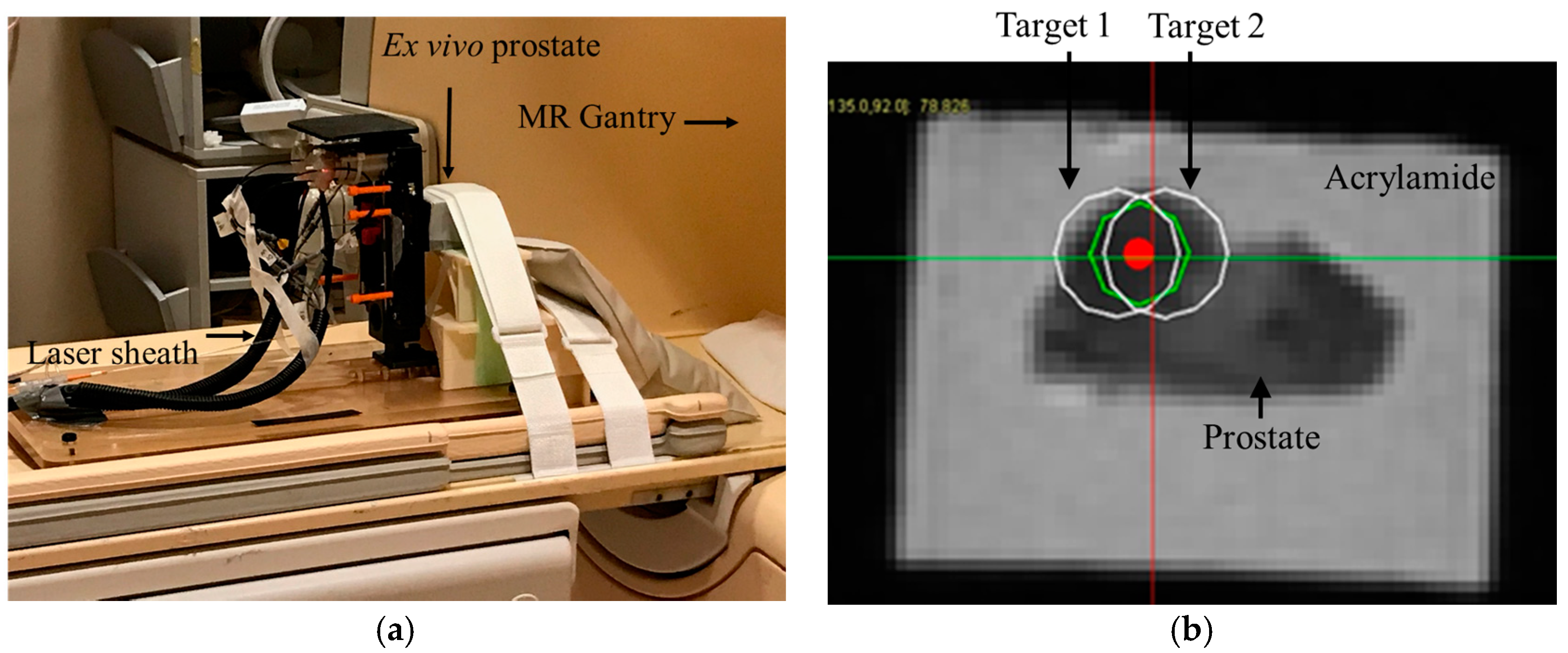
Next, an opening was created on one of the faces of the casing of the phantom to allow transperineal needle access during MRI ablation experiment. The phantom was secured in front of the robot as shown in Figure 7a.
During the in-gantry experiment, the robot was initially scanned and registration was performed using the same method as described earlier. Then, a high resolution T2w image was acquired. The ablation plan was then superimposed on the T2w image.
Figure 8 shows a screenshot of the OncoNav with ablation plan. Since the ablation area was relatively large, the software suggested the minimum number of ablations which still covered the whole area with some safety margin [18] to be two. Figure 7b shows a close-up view of the Axial T2w image with superimposed ablation plan. Each planned ablation zone was an ellipsoid with 19 mm long axis and 14 mm short axis.
Next, the robot was commanded to targets 1 and 2, respectively. An MRI compatible needle with a plastic sheath (Medtronic, Minneapolis, MN, USA) was inserted to the depth calculated by the robot controller. The needle was removed while the plastic sheath was left behind. Next, the saline cooled catheter was inserted 5 mm ahead of the required depth (per recommendation of the manual) and the target was ablated at 15 W for 90 s. A confirmation T2w image was acquired. Finally, the ex vivo prostate was removed and sliced for gross observation.

3. Results

In-Air Accuracy:Figure 9a shows the target points and their locations within the workspace. Figure 9b shows the mean and std. of the positioning error for each target. Error was defined as the 2D distance between the desired location and the actual location of the robot end effector (needle guide). The overall accuracy was 0.38 ± 0.27 mm.
Phantom accuracy: Figure 10 shows CT images of the phantom for all of the four targets. The error was defined as the 2D distance between the center of spherical metal fiducial and the needle tip. The targeting accuracy was 2.17 ± 0.47 mm.
Ablation Results: The thermochromic phantom had 4 metal spheres and the FLA was applied for 90 s at 15 W for two (out of four) targets. Figure 11a shows the ablation area in pink. Following the ablation in the cadaver prostate, the phantom was sliced for gross observation. Figure 11c show the ablated area compared to the planned zone in Figure 11b.

4. Discussion

The small in the air error (robot-only) is mainly caused by the backlash in the timing belt, which can be improved by adding to the tension of the timing belt. The error under CT is larger since it includes the mechanical error (in-the-air) and registration error (for more details regarding the error components, please refer to [19]. The registration error in MR guided was 2.5 mm. The error was reported using CT since we have metal fiducials as ground truth (in MR, we rely on virtual targets which are subject to error due to move and tissue deformation).
Overall, we demonstrated that the robot can accurately reach targets within its MRI gantry workspace, with physical constraints compatible with a patient in lithotomy in-gantry position. We also demonstrated that the robot can accurately reach a target under image guidance. Also, the ablation was evaluated both in the phantom and in an ex vivo prostate tissue in terms of target tumor margin coverage. Integration of a custom software system to a commercial laser ablation hardware device and a custom MRI-compatible robot was completed, allowing for truly integrated planning, navigation, monitoring, and confirmation of a cadaver prostate target. Regulatory pathways are yet to be implemented, but feasibility in the MRI environment was shown to be accurate. Although speculative, this was possible potentially without as many cumbersome workflows commonly seen with commercial MRI thermometry software poorly integrated to a variety of vendor MRIs.

5. Conclusions

Novel custom robotics hardware and software integration were successfully tested and deployed in phantom and in a human prostate cadaver with cancer. The robot was able to accurately target needles. The ablation workflow using the robot was subjectively smooth and the gross observation demonstrated coverage of the planned target tumor margins. FLA using this robot is feasible and may address ongoing clinical needs for accurate needle-based procedures in prostate cancer.

Author Contributions

Conceptualization, R.S., Y.C., A.S., Z.T., S.X., and B.J.W.; Methodology, R.S., M.L., S.X., Z.T.H.T, and B.J.W.; Phantom, A.H.N.; Tissue procurement: I.B., MRI reading: I.B.T., Validation, R.S., M.L., and S.X.; Formal Analysis, R.S.; Resources, P.C.; Writing-Original Draft Preparation, R.S.; Writing-Review & Editing, all; Supervision, B.J.W.; Funding Acquisition, Z.T.H.T, S.X., and B.J.W.

Funding

This work was supported in part by the Intramural Research Program of the NIH and the NIH Center for Interventional Oncology. This research received 2015 NIH Bench to Bed Award. R.S., M.L., S.X., A.N., I.B., and B.W. were supported by Intramural funding on of NIH grant 1ZIDBC011242 and 1ZIDCL040015.

Acknowledgments

The authors would like to thank Dagane Daar, MRI technologist for his support during data collection. The authors also thank Science Care for providing a human prostate tissue from donors with cancer.

Conflicts of Interest

The authors declare no conflicts of interest.

References

  1. Siegel, R.; Miller, K.; Jemal, A. Cancer statistics. CA Cancer J. Clin. 2018, 68, 7–30. [Google Scholar] [CrossRef] [PubMed]
  2. Tareen, B.; Godoy, G.; Taneja, S.S. Focal therapy: A new paradigm for the treatment of prostate cancer. Rev. Urol. 2009, 11, 203–212. [Google Scholar] [PubMed]
  3. Cepek, J.; Lindner, U.; Davidson, S.R.; Haider, M.A.; Ghai, S.; Trachtenberg, J.; Fenster, A. Treatment planning for prostate focal laser ablation in the face of needle placement uncertainty. Med. Phys. 2014, 41, 013301. [Google Scholar] [CrossRef] [PubMed]
  4. Stoianovici, D.; Kim, C.; Srimathveeravalli, G.; Sebrecht, P.; Petrisor, D.; Coleman, J.; Solomon, S.B.; Hricak, H. MRI-safe robot for endorectal prostate biopsy. IEEE/ASME Trans. Mechatron. 2014, 19, 1289–1299. [Google Scholar] [CrossRef] [PubMed]
  5. Fischer, G.S.; Iordachita, I.; Csoma, C.; Tokuda, J.; DiMaio, S.P.; Tempany, C.M.; Hata, N.; Fichtinger, G. MRI-compatible pneumatic robot for transperineal prostate needle placement. IEEE/ASME Trans. Mechatron. 2008, 13, 295–305. [Google Scholar] [CrossRef] [PubMed]
  6. Krieger, A.; Iordachita, I.; Guion, P.; Singh, A.K.; Kaushal, A.; Ménard, C.; Pinto, P.A.; Camphausen, K.; Fichtinger, G.; Whitcomb, L.L. An MRI-compatible robotic system with hybrid tracking for MRI-guided prostate intervention. IEEE Trans. Biomed. Eng. 2011, 58, 3049–3060. [Google Scholar] [CrossRef] [PubMed]
  7. Song, S.-E.; Tokuda, J.; Tuncali, K.; Tempany, C.M.; Zhang, E.; Hata, N. Development and preliminary evaluation of a motorized needle guide template for MRI-guided targeted prostate biopsy. IEEE Trans. Biomed. Eng. 2013, 60, 3019–3027. [Google Scholar] [CrossRef] [PubMed]
  8. Goldenberg, A.A.; Trachtenberg, J.; Kucharczyk, W.; Yi, Y.; Haider, M.; Ma, L.; Weersink, R.; Raoufi, C. Robotic system for closed-bore MRI-guided prostatic interventions. IEEE/ASME Trans. Mechatron. 2008, 13, 374–379. [Google Scholar] [CrossRef]
  9. Seifabadi, R.; Aalamifar, F.; Iordachita, I.; Fichtinger, G. Toward teleoperated needle steering under continuous MRI guidance for prostate percutaneous interventions. Int. J. Med. Robot. Comput. Assist. Surg. 2016, 12, 355–369. [Google Scholar] [CrossRef] [PubMed]
  10. Monfaredi, R.; Cleary, K.; Sharma, K. MRI Robots for Needle-Based Interventions: Systems and Technology. Ann. Biomed. Eng. 2018, 46, 1479–1497. [Google Scholar] [CrossRef] [PubMed]
  11. Chen, Y.; Squires, A.; Seifabadi, R.; Xu, S.; Agarwal, H.K.; Bernardo, M.; Pinto, P.A.; Choyke, P.; Wood, B.; Tse, Z.T.H. Robotic system for MRI-guided focal laser ablation in the prostate. IEEE/ASME Trans. Mechatron. 2017, 22, 107–114. [Google Scholar] [CrossRef]
  12. Chen, Y.; Xu, S.; Squires, A.; Seifabadi, R.; Turkbey, I.B.; Pinto, P.; Choyke, P.; Wood, B.; Tse, Z.T.H. MRI Guided Robotically Assisted Focal Laser Ablation of the Prostate Using Canine Cadavers. IEEE Trans. Biomed. Eng. 2017, 65, 1434–1442. [Google Scholar] [CrossRef] [PubMed]
  13. Moyer, I.E. 2012 “Core [X,Y]”. Available online: http://corexy.com/index.html (accessed on 26 November 2018).
  14. Chen, Y.; Godage, I.S.; Tse, Z.T.H.; Webster, R.J.; Barth, E.J. Characterization and Control of a Pneumatic Motor for MR-Conditional Robotic Applications. IEEE/ASME Trans. Mechatron. 2017, 22, 2780–2789. [Google Scholar] [CrossRef]
  15. Boley, D.L.; Steinmetz, E.S.; Sutherland, K.T. Robot localization from landmarks using recursive total least squares. In Proceedings of the 1996 IEEE International Conference on Robotics and Automation, Minneapolis, MN, USA, 22–28 April 1996; pp. 1381–1386. [Google Scholar]
  16. Negussie, A.H.; Partanen, A.; Mikhail, A.S.; Xu, S.; Abi-Jaoudeh, N.; Maruvada, S.; Wood, B.J. Thermochromic tissue-mimicking phantom for optimisation of thermal tumour ablation. Int. J. Hyperth. 2016, 32, 239–243. [Google Scholar] [CrossRef] [PubMed]
  17. Orban, M.; Kurin-Csoergei, K.; Zhabotinsky, A.M.; Epstein, I.R. Pattern Formation during Polymerization of Acrylamide in the Presence of Sulfide Ions. J. Phys. Chem. B 1999, 103, 36–40. [Google Scholar] [CrossRef] [Green Version]
  18. Xu, S.; Agarwal, H.; Bernardo, M.; Seifabadi, R.; Turkbey, B.; Partanen, A.; Negussie, A.; Glossop, N.; Choyke, P.; Pinto, P.; et al. An MRI guided system for prostate laser ablation with treatment planning and multi-planar temperature monitoring. In Medical Imaging 2016: Image-Guided Procedures, Robotic Interventions, and Modeling; International Society for Optics and Photonics (SPIE): Bellingham, WA, USA, 2016; Volume 9786, p. 97861I. [Google Scholar]
  19. Seifabadi, R.; Cho, N.B.; Song, S.E.; Tokuda, J.; Hata, N.; Tempany, C.M.; Fichtinger, G.; Iordachita, I. Accuracy study of a robotic system for MRI-guided prostate needle placement. Int. J. Med. Robot. Comput. Assist. Surg. 2013, 9, 305–316. [Google Scholar] [CrossRef] [PubMed]
Figure 1. Focal laser ablation concept and system (a) Focal Laser ablation of prostate using a grid template; (b) Visualase™ focal laser ablation (FLA) system.
Jimaging 04 00140 g001
Figure 2. An MRI-guided robot assisted focal laser ablation system components.
Jimaging 04 00140 g002
Figure 3. Robot hardware: (a) Comparison of the old and new robot (left: old, right: new); (b) the robot; (c) The CoreXY stage; and (d) the rotation arm to allow needle angulation (top view).
Jimaging 04 00140 g003
Figure 4. Air motor design concept.
Jimaging 04 00140 g004
Figure 5. (a) Fiducial markers were positioned with respect to the robot’s frame at an offset of 50 mm perpendicular to the transverse plane of the robot, to eliminate the potential artifact caused by the guiding brass rods. Green arrows show the five fiducial markers, and white arrows show the five fiducial markers within the image. (b) Top view of the inside of the robot’s controller.
Jimaging 04 00140 g005
Figure 6. A phantom study in the CT suite: N = 4 spherical metal targets were embedded into the phantom. After targeting of all fiducials to investigate robot accuracy, FLA was done on a thermochromics phantom for 2 of the targets. (a) Front view and (b) back view.
Jimaging 04 00140 g006
Figure 7. Ex vivo FLA study under MRI guidance. A human prostate tissue from a donor who passed away from metastatic prostate cancer was molded in an acrylamide gel phantom. Multi-focal FLA was done on a suspicious and relatively large area identified in the MRI. (a) Robot setup. An endorectal coil was placed under the prostate specimen. (b) T2w image showing bi-focal ablation plan.
Jimaging 04 00140 g007
Figure 8. A screen shot showing the OncoNav software, which was used for ablation planning, temperature monitoring, robot control, and validation purposes.
Jimaging 04 00140 g008
Figure 9. In air accuracy results: (a) five random targets were chosen within the robot workspace and (b) the error distribution for each target.
Jimaging 04 00140 g009
Figure 10. CT images post needle insertion for each target. Top row shows the entire phantom. The bright spots show the needle and fiducial. Bottom row shows close-up views of the distance between fiducials and needle. (ad) are targets 1, 2, 3, and 4, respectively.
Jimaging 04 00140 g010
Figure 11. Focal laser ablation in (a) thermochromic phantom (b) ablation plan: green circle is the target zone to be ablated, white circles are the two suggested ablation zones by the software to cover the target zone, red and yellow dots are centers of the target zone and planned zone, respectively, and (c) cross section of the prostate post-ablation. Dashed green circle shows the planned ablation zone while the gray contour shows the ablated zone.
Jimaging 04 00140 g011

